
Initial Print Date:08/02
Revision Date:
Subject
Page
Purpose of the System . . . . . . . . . . . . . . . . . . . . . . . . . . . . . . . . . . . . . .3
System Components . . . . . . . . . . . . . . . . . . . . . . . . . . . . . . . . . . . . . . . .4
Battery . . . . . . . . . . . . . . . . . . . . . . . . . . . . . . . . . . . . . . . . . . . . . . . . .4
Battery Cable Routing . . . . . . . . . . . . . . . . . . . . . . . . . . . . . . . . . . . . . .4
Monitored B+ Cable . . . . . . . . . . . . . . . . . . . . . . . . . . . . . . . . . . . . . . .5
Fuse Box and Fuses . . . . . . . . . . . . . . . . . . . . . . . . . . . . . . . . . . . . . . .6
Ground Points . . . . . . . . . . . . . . . . . . . . . . . . . . . . . . . . . . . . . . . . . . .7
Alternator . . . . . . . . . . . . . . . . . . . . . . . . . . . . . . . . . . . . . . . . . . . . . . .7
Bus Systems . . . . . . . . . . . . . . . . . . . . . . . . . . . . . . . . . . . . . . . . . . . .9
Review Questions . . . . . . . . . . . . . . . . . . . . . . . . . . . . . . . . . . . . . . . . .10
Table of Contents
Power Supply and Bus Systems

2
Power Supply and Bus Systems
Power Supply and Bus Systems
Model: E85
Production: Start of Production MY 2003
Objectives:
After completion of this module you should be able to:
•
Locate the Main power supply cable and fuses.
•
Understand the construction of the B+ battery cable.
•
Know the Bus System Layout.
3
Power Supply and Bus Systems
Purpose of the System
Power Supply
The purpose of the Power Supply System is to safely deliver the required voltage and
amperage to vehicle systems. The power supply system includes vehicle ground points and
fuses. The power supply system includes the following components:
•
Battery
•
Monitored Battery B+ Cable (New System)
•
Fuse Box
•
Fuses
• Ground
Points
•
Alternator
•
Jumper Cable Point
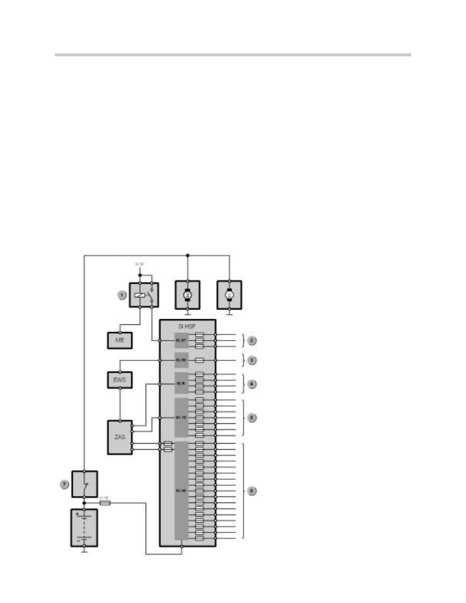
Power Supply Block Diagram
1.
Main Relay
2.
KL30
3. KL15
4.
KLR
5.
KL50
6.
KL87
7.
BST
G
Alternator
M
Starter Motor
ZAS
Ignition Switch
DME
Engine Control Module
EWS
SI HSF Fusebox (Behind Glove Box)
4
Power Supply and Bus Systems
System Components
Battery
The Battery is located in the luggage compartment right hand side. Battery power is split
with one leg routed through a 250 amp fuse to the main fuse box behind the glove box.
The other circuit is sent through the BST and to the new monitored B+ cable that supplies
power to the starter and alternator.
Depending on equipment on the vehicle either a 50AH, 70AH or 80AH battery is installed.
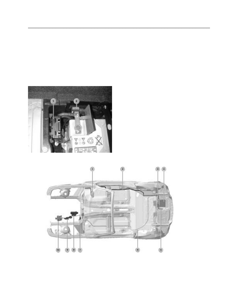
Battery located in Luggage Compartment
1. Rear Fuse Box With 250 Amp fuse.
2. Monitored B+ Cable With BST.
Battery Cable Routing
1. Passenger Compartment Fuse Box
6. Monitored B+ Cable
2. B+ Cable to Passenger Compartment Fuse Box
7. Jumper Terminal Under Hood
3. Rear Fuse Box
8. Starter
4. Battery
9. B+ Cable Connector
5. BST
10. Generator
Battery Cable Routing
5
Power Supply and Bus Systems
Monitored B+ Cable
The Monitored B+ Cable is a mutli strand aluminum cable with a cross section of 80mm
2
.
The aluminum cable is sheathed with an insulating layer and surrounded by a detecting
shielded cable. An outer insulating sheath covers the entire assembly.
The Monitored B+ cable is routed underneath the vehicle from the battery box along the
floor pan to the engine compartment jumper cable point. The B+ cable is attached to the
underside of the body with two different style clips. The cable is protected with plastic
shielding. (Description of cable monitoring is found in Safety Systems.)
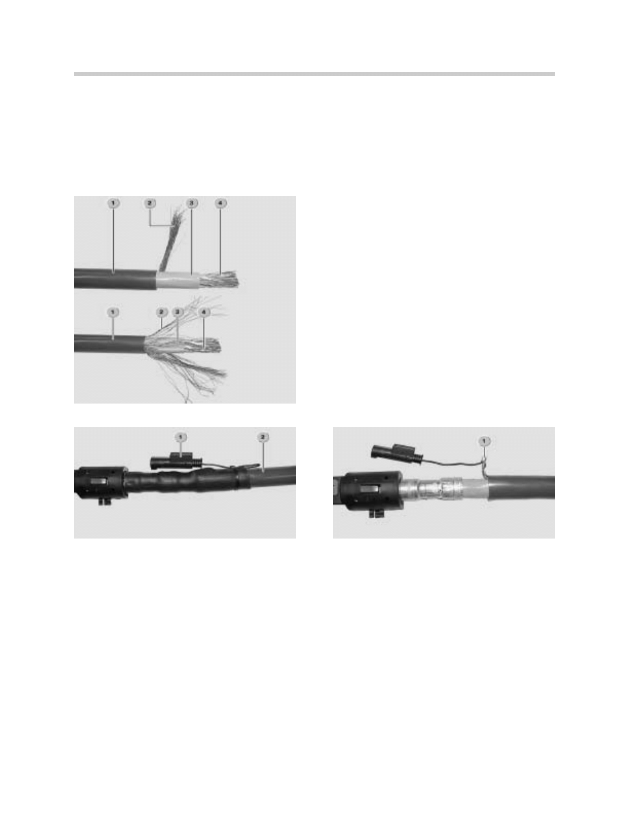
Monitor Connections
1. Connections for B+ Cable Monitoring
2. Monitored B+ Battery Cable
Monitoring Battery Cable Construction
1. Outer Insulation
2. Detecting Shield
3. Inner Insulation
4. Multi-Strand Aluminum Cable
Monitor Connections
1. Connections for B+ Cable Monitoring
2. Monitored B+ Battery Cable
6
Power Supply and Bus System
Fuse Box and Fuses
The Fuse Box is located behind the glove box and accessible by removing the glove box
door and underdash panel. The fuse box contains blade type fuse and special fuses for
higher amperage consumers. Relays are located on both the front and back sides of the
fuse box.
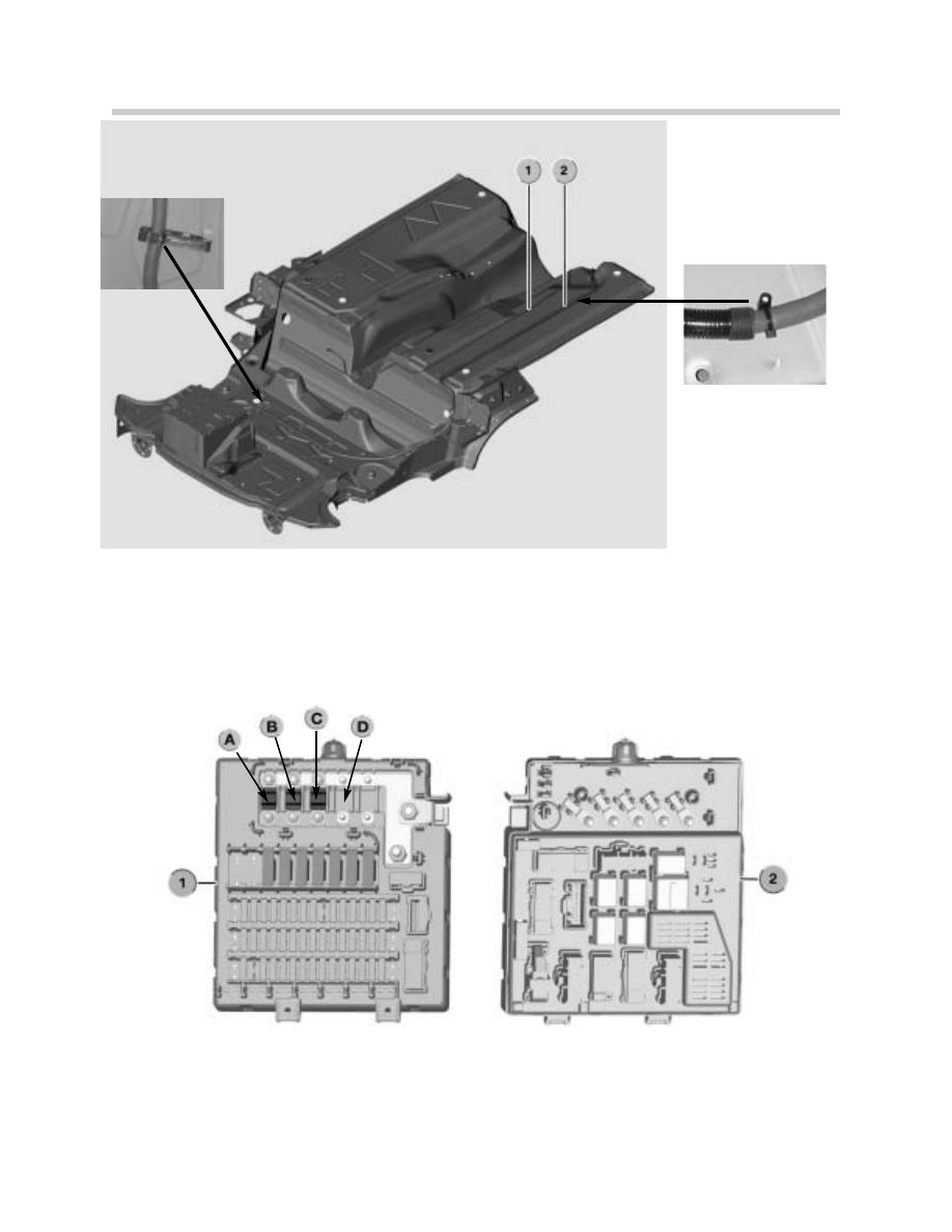
B+ Cable Routing
1. Fuel Line
2. B+ Battery Cable
Passenger Compartment Fuse Box
1. Fuse Box Front View
A. Electric Engine Cooling Fan
2. Fuse Box Rear View
B. Not Used
C. DME
D. EPS
7
Power Supply and Bus Systems
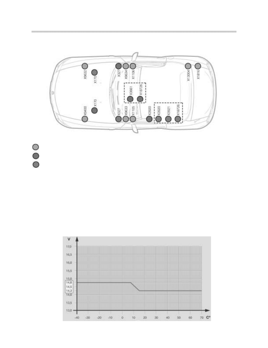
Ground Points
Alternator
Depending on country and equipment the vehicle is equipped with different output alterna-
tors.
Battery charging voltage varies according to ambient temperature. At lower temperatures,
the battery is less suseptable to boiling over and can be charged at higher voltages. At high
temperature the charging voltage is reduced to prevent loss of the battery electrolyte
through evaporation.
The DME controls the output rate of the alternator.
Ground points in Left and Right Hand Drive Vehicles
Ground points in Left Hand Drive Vehicles
Ground points in Right Hand Drive Vehicles
8
Power Supply and Bus Systems
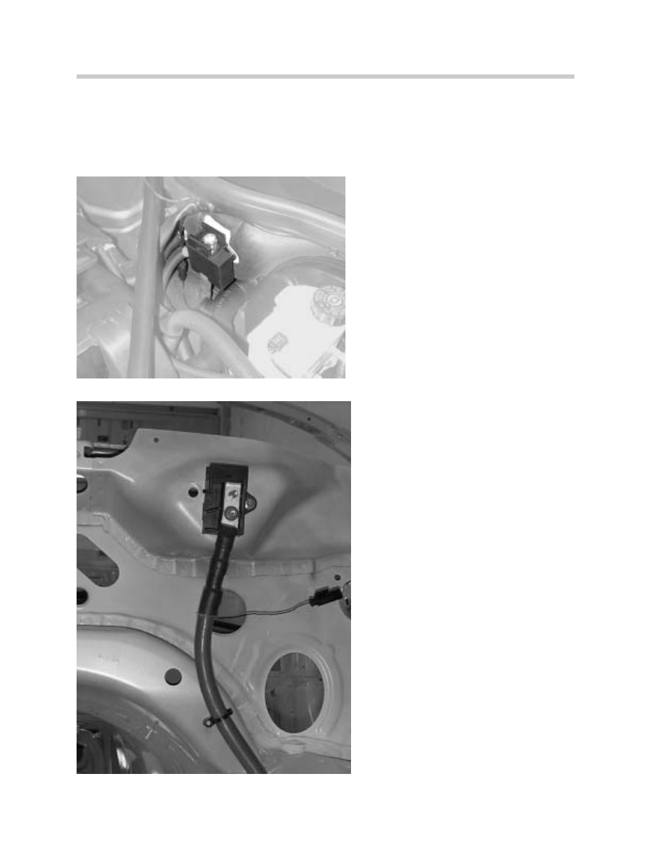
Jumper Cable Point
The Jumper Cable Point is located in the engine compartment on the left side at the fire-
wall. The jumper cable point is the junction for the Monitored B+ cable and the alternator
and starter.
Jumper Cable Point
Cable Routing on Firewall
9
Power Supply and Bus Systems
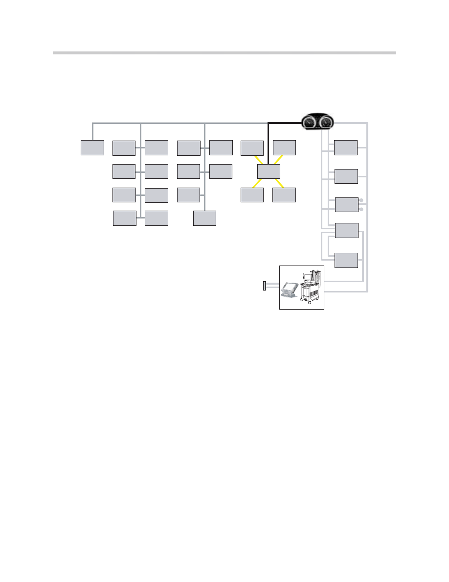
Bus Systems
The bus system of the E85 is based on the K-Bus, PT CAN and the D-Bus of the E46.
The byteflight optical bused system is based on the E65.
SBSL
SBSR
STVL
STVR
SIM
GM5
EWS III
PDC
RLS
SZM
CVM
SM
LSZ
RADIO
CID
CDC
NAV
HIFI
TEL
EGS/
SMG
DME
DSC
EPS
LWS
OBD II
BYTEFLIGHT
PT-CAN
IHKA/
IHKS
K-BUS
K- Bus
IHKA
Automatic Climate Control
IHKS
Manual Air Conditioning
IHS
Heating System
GM5
General Module
RLS
Rain/Light Sensor
SZM
Console Switch Block
SM Seat
Memory
EWSIII
EWS
PDC
Park Distance Control
CVM
Convertible Top Module
LSZ
Light Control Module
Radio
Radio
CDC
CD Changer
HiFi
Optional Audio System
CID
Central Information Display
NAV
Navigation System
VM Video
Module
TEL
Telephone Control Unit
byteflight
SIM
Safety and Information
Module
SBSL
Satellite B-pillar left
SBSR
Satellite B-pillar right
STVL
Satellite Door Left
STVR
Satellite Door Right
PT CAN
LWS
Steering Angle Sensor
EPS
Electric Power Steering
DSC
Dynamic Stability Control
DME
Digital Motor Electronics
EGS
Automatic Transmission
Control
SMG
Sequential Manual
Transmission Control
D-Bus
IKE
Instrument Cluster Electronics
LWS
Steering Angle Sensor
EPS
Electric Power Steering
DSC
Dynamic Stability Control
OBD II
DME
Digital Motor Electronics
EGS
Automatic Transmission
Control
SMG
Sequential Manual
Transmission Control

10
Power Supply and Bus Systems
Review Questions
1. What new about the B+ cable?
2. Where in the vehicle is the fuse for the EPS located and what is the amperage rating?
3. What is the advantage of the increased charging voltage of the battery?
4. How is the voltage supply cable to the fuse box protected in case of a short to ground?
5. The module SBSL is located on which Bus system?
Document Outline
- Main Menu
- E85 Complete Vehicle
- E85 BodyShell
- M54 Engine
- MS45 DME Part 1
- MS45 DME Part 2
- MS45 DME Part 3
- MS45 DME Part 4
- E85 Driveline
- E85 Chassis Dynamics
- E85 Heating & Air Cond
- E85 PowerSupply
- E85 Adv Safety Elec.
- E85 Driver Information
- E85 Central Body Elec.
- E85 Communciations
- E85 Updates
Wyszukiwarka
Podobne podstrony:
04a E85 Power Supply and Bus Systems
Convert Computer ATX Power Supply to Lab Power Supply
Jvc Power Supply Description And Trouble Shooting Procedure
Battery Inverter For Modularly Structured Pv Power Supply Systems
0 50V 2A LM10C, 0 50V 2A Bench power supply circuit diagrams, schematics, electronic projects
(Wydruk – ATX Switching Power Supply 13,8 V Proste zmiany w celu zwiększenia napięcia wyjściowego Ja
Alarm Power Supply L78Sxx id 61 Nieznany (2)
3 2 Lab Install Power Supply
HY3010 power supply, Elektronika, Zasilacze, Zasilacz HY3010, Zasilacz HY3010, HY3010 ,INSTRUKCJA
Lekturki Power Supply Unit Lekturka
How to Modify an ATX Computer Power Supply
Adaptive fuzzy control for uninterruptible power supply with three phase PWM inverter
Control and Power Supply for Resistance Spot Welding (RSW)
Performance Improvements in an arc welding power supply based on resonant inverters (1)
Convert Computer ATX Power Supply to Lab Power Supply
(ebook free energy) 50000 vdc power supply
(ebook electronics) Schematics Power Regulated Power Supply for CB & Ham Radio
Sovereign XS Power Supply Schematic
03a E46 Power Supply and Bus Systems
więcej podobnych podstron