
U.S. ARMY MEDICAL DEPARTMENT CENTER AND SCHOOL
FORT SAM HOUSTON, TEXAS 78234-6100
ELECTROSURGICAL
APPARATUS
SUBCOURSE MD0363 EDITION 100

DEVELOPMENT
This subcourse is approved for resident and correspondence course instruction. It
reflects the current thought of the Academy of Health Sciences and conforms to printed
Department of the Army doctrine as closely as currently possible. Development and
progress render such doctrine continuously subject to change.
ADMINISTRATION
Students who desire credit hours for this correspondence subcourse must enroll in the
subcourse. Application for enrollment should be made at the Internet website:
http://www.atrrs.army.mil. You can access the course catalog in the upper right corner.
Enter School Code 555 for medical correspondence courses. Copy down the course
number and title. To apply for enrollment, return to the main ATRRS screen and scroll
down the right side for ATRRS Channels. Click on SELF DEVELOPMENT to open the
application; then follow the on-screen instructions.
For comments or questions regarding enrollment, student records, or examination
shipments, contact the Nonresident Instruction Branch at DSN 471-5877, commercial
(210) 221-5877, toll-free 1-800-344-2380; fax: 210-221-4012 or DSN 471-4012, e-mail
accp@amedd.army.mil, or write to:
NONRESIDENT INSTRUCTION BRANCH
AMEDDC&S
ATTN:
MCCS-HSN
2105 11TH STREET SUITE 4191
FORT SAM HOUSTON TX 78234-5064
Be sure your social security number is on all correspondence sent to the Academy of
Health Sciences.
CLARIFICATION OF TERMINOLOGY
When used in this publication, words such as "he," "him," "his," and "men" 'are intended
to include both the masculine and feminine genders, unless specifically stated otherwise
or when obvious in context.
USE OF PROPRIETARY NAMES
The initial letters of the names of some products may be capitalized in this subcourse.
Such names are proprietary names, that is, brand names or trademarks. Proprietary
names have been used in this subcourse only to make it a more effective learning aid.
The use of any name, proprietary or otherwise, should not be interpreted as
endorsement, deprecation, or criticism of a product; nor should such use be considered
to interpret the validity of proprietary rights in a name, whether it is registered or not.

MD0363 i
TABLE OF CONTENTS
Lesson
Paragraphs
INTRODUCTION
1
PREVENTIVE MAINTENANCE CHECKS AND SERVICES
AND VERIFICATION/CALIBRATION
Section I. Preventive Maintenance Checks and Services ............ 1-1 -- 1-7
Section
II.
Verification/
Calibration ................................................ 1-8 -- 1-10
Exercises
2
MALFUNCTIONS AND DEFECTIVE MODULES
Section I. Isolate Malfunctions to Module Level in
Electrosurgical
Apparatus ............................................ 2-1 -- 2-2
Section II. Remove and Replace Defective Modules of
Electrosurgical
Apparatus ............................................ 2-3 -- 2-6
Exercises
APPENDIX, HYFRECATOR TROUBLESHOOTING GUIDELINE

MD0363 ii
CORRESPONDENCE COURSE OF
THE U.S. ARMY MEDICAL DEPARTMENT CENTER AND SCHOOL
SUBCOURSE MD0363
ELECTROSURGICAL APPARATUS
INTRODUCTION
An electrosurgical apparatus generates high frequency current. The hyfrecator is
one example of electrosurgical apparatus which generates current used for desiccation,
fulguration, and coagulation procedures which do not require cutting. Although used as
early as 1900, the hyfrecator did not become popular until 1937 when low-cost modality
became available. Literally hundreds of techniques have been developed using the
hyfrecator. This subcourse discusses the Birtcher hyfrecator and procedures that you,
as a medical equipment repairer, need to use to keep it functioning at maximum
efficiency. The procedures covered here are: performing preventive maintenance
checks and services (PMCS); calibrating/verifying; isolating malfunctions to the module
level; and removing and replacing defective modules of the electrosurgical apparatus,
the hyfrecator.
Subcourse Components:
This subcourse consists of two lessons and an appendix.
Lesson 1, Preventive Maintenance Checks and Services and
Verification/Calibration.
Lesson 2, Malfunctions and Defective Modules.
Appendix,
Hyfrecator
Troubleshooting Guideline.
Here are some suggestions that may be helpful to you in completing this
subcourse:
--Read and study each lesson carefully.
--Complete the subcourse lesson by lesson. After completing each lesson, work
the exercises at the end of the lesson, marking your answers in this booklet.

MD0363 iii
--After completing each set of lesson exercises, compare your answers with those
on the solution sheet that follows the exercises. If you have answered an exercise
incorrectly, check the reference cited after the answer on the solution sheet to
determine why your response was not the correct one.
Credit Awarded:
Upon successful completion of the examination for this subcourse, you will be
awarded 5 credit hours.
To receive credit hours, you must be officially enrolled and complete an
examination furnished by the Nonresident Instruction Branch at Fort Sam Houston,
Texas.
You can enroll by going to the web site http://atrrs.army.mil and enrolling under
"Self Development" (School Code 555).
A listing of correspondence courses and subcourses available through the
Nonresident Instruction Section is found in Chapter 4 of DA Pamphlet 350-59, Army
Correspondence Course Program Catalog. The DA PAM is available at the following
website: http://www.usapa.army.mil/pdffiles/p350-59.pdf.

MD0363 1-1
LESSON ASSIGNMENT
LESSON 1
Preventive Maintenance Checks and Services and
Verification/Calibration.
TEXT ASSIGNMENT
Paragraphs 1-1 through 1-10.
TASKS TAUGHT Perform
preventive
maintenance checks and services on
the electrosurgical apparatus.
Perform calibration/verification of the electrosurgical
apparatus.
LESSON OBJECTIVES
When you have completed this lesson, you should be
able to:
1-1.
Identify the function of electrosurgical apparatus
controls and indicators.
1-2.
Identify
the
three
technique configurations.
1-3.
Identify all safety precautions.
1-4.
Identify the steps for quarterly preventive
maintenance checks and services
.
1-5.
Identify
the
procedures
for verifying calibration of
the electrosurgical device.
1-6.
Identify
the
procedures for calibrating the
electrosurgical
apparatus.
1-7.
Identify the apparatus specifications.
SUGGESTION
Work the lesson exercises at the end of this lesson
before beginning the next lesson. These exercises will
help you accomplish the lesson objectives.

MD0363 1-2
LESSON 1
PREVENTIVE MAINTENANCE CHECKS AND SERVICES
AND
CALIBRATION/VERIFICATION
Section I. PREVENTIVE MAINTENANCE CHECKS AND SERVICES
1-1. GENERAL
You must ensure the Birtcher Hyfrecator continues to function efficiently. This
lesson introduces the general operation of the hyfrecator, its controls and configurations,
the safety precautions you need to follow, and the procedures you use for quarterly PMCS
and calibration/verification.
1-2. TERMINOLOGY
Terminology describing the application of high frequency currents may create some
confusion. The following definitions will help you understand the terms.
a. Monoterminal, Monopolar, or Oudin Current. A high-frequency, high-voltage
current discharging from one outlet or terminal to the patient is variously described as
monoterminal, monopolar, or as an Oudin current.
b. Bipolar, Bi-terminal, or Bi-active. Current traveling from a high-frequency
oscillator through an active cable, an electrode, a small area of tissue, and through
another electrode and cable.
c. Application.
(1)
Monoterminal
application of the high frequency current may have an effect
upon tissue varying from very light and superficial dehydration to relatively deep
penetration and destruction.
(2)
Bipolar
application
may create an effect in tissue varying from insufficient
to very heavy coagulation.
(3) Either application carried to extreme intensity or long duration will cause
carbonization or charring.
1-3. CONTROLS
AND
STATUS INDICATORS
Review the functions of the following controls and status indicators to ensure that
you understand their purpose and how they function. The number at the end of each
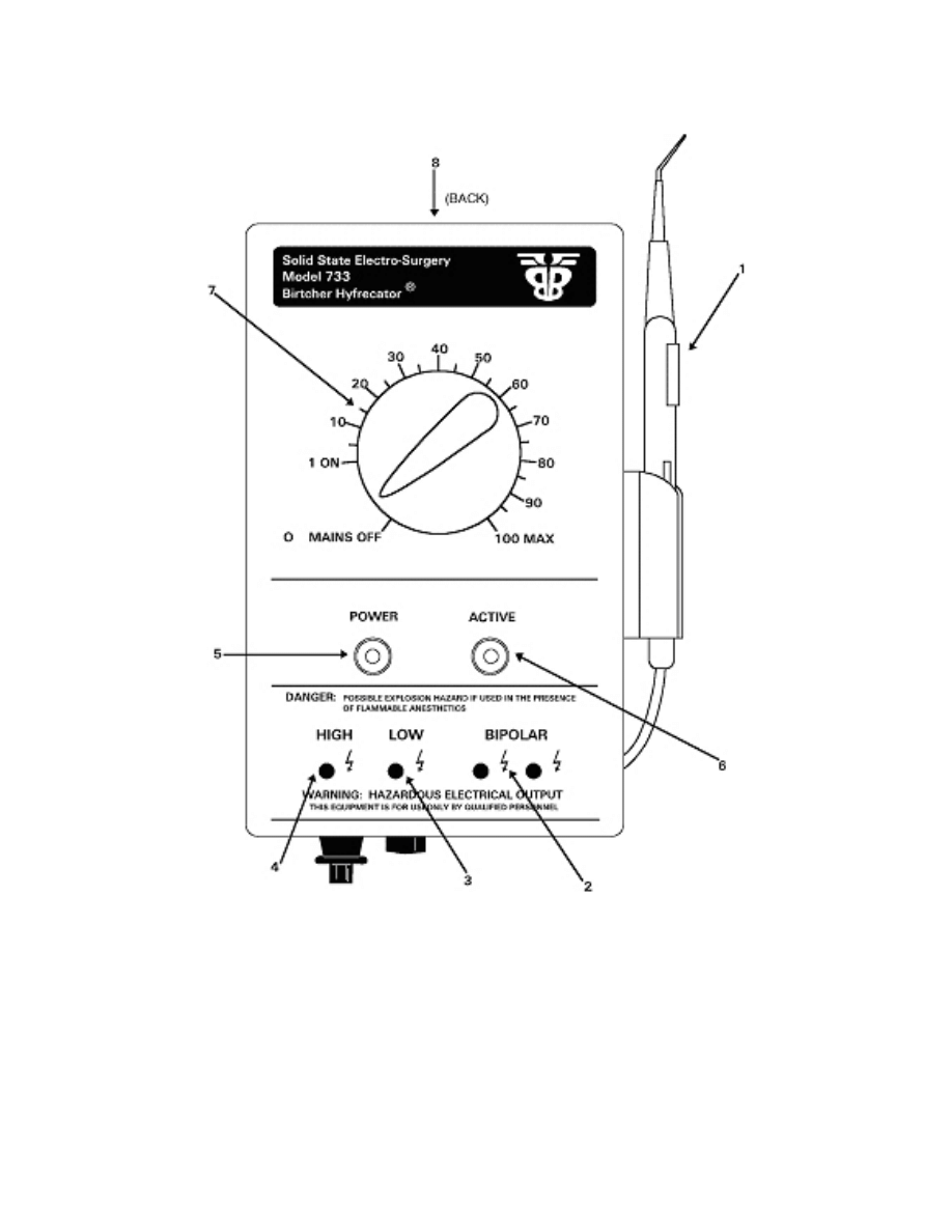
control or indicator refers to the item in figure 1-1.
MD0363 1-3
Figure 1-1. Birtcher hyfrecator.
a. Foot Switching Model 733FS. This model includes a 711-A handle. The 790
foot switch is supplied as an accessory. (See figure 1-1).
b. Hand Switching Model 733SW. The 733SW is a hand switching model. The
711-SW switching handle is supplied as an accessory.

MD0363 1-4
c. Switching
Handle
(1). Both the 711-SW handle and the 711-B needle
electrode are shown.
d. BIPOLAR Outlets (2). You use the BIPOLAR outlets for bipolar (bi-active or bi-
terminal) coagulation techniques. The BIPOLAR outlets are of equal power. The 789 set
is available with two tips, one for each BIPOLAR outlet. Single needle techniques require
that an indifferent plate electrode (Birtcher 706) be plugged into one of the BIPOLAR
outlets and the tip for the electrode handle be plugged into the other.
e. LOW Outlet (3). The LOW outlet is a single active terminal. You use it for light
desiccation and fulguration techniques requiring low intensity, or monoterminal current.
f. HIGH Outlet (4). The HIGH outlet is a single active terminal. You use it for
heavier desiccation and fulguration techniques requiring higher intensity or monoterminal
techniques.
g. ON/OFF Pilot Light (5). The ON/OFF pilot light lights only when you turn the
control dial (item 7) clockwise from the OFF to ON position.
h. ACTIVE Circuit Pilot Light (6). The ACTIVE pilot light lights only when you
activate the foot switch or hand switch.
i. Control
Dial
(7). You use the control dial to select current intensity from "0"
(MAINS OFF) to "100" (MAX).
j. Audio
Adjust
(8). You use the audio adjust dial to control the buzzer level
volume.
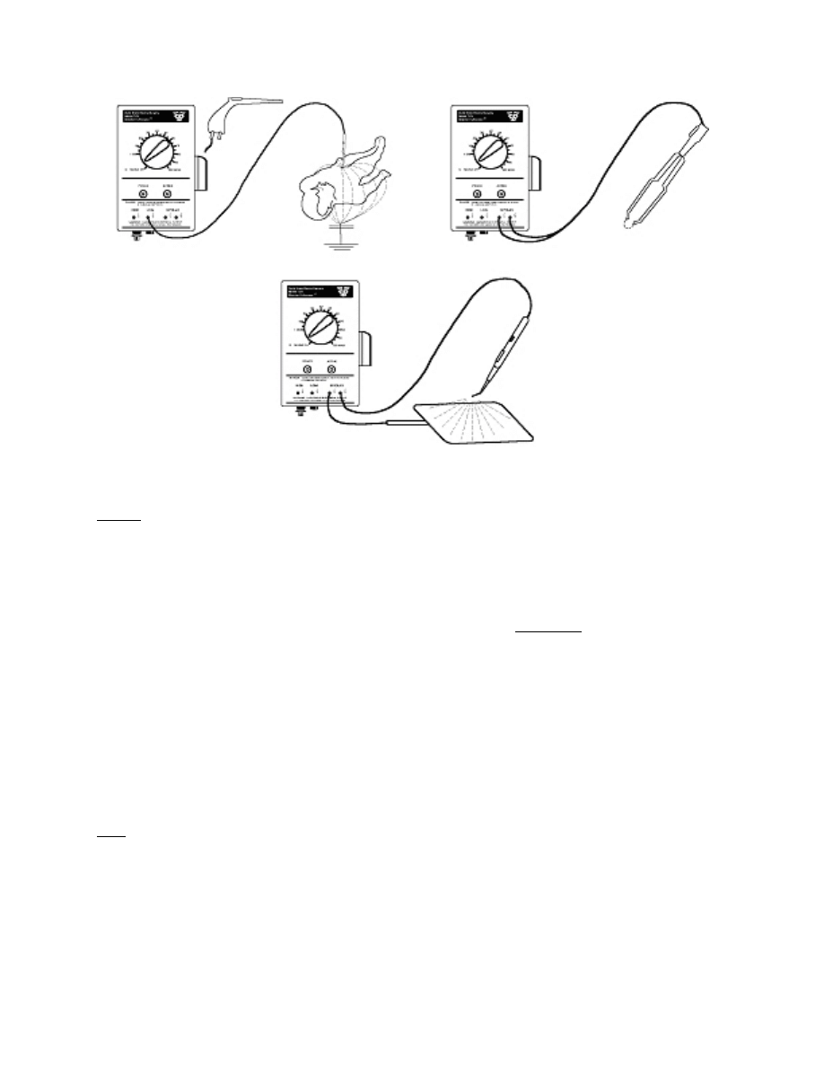
1-4. TECHNIQUE CONFIGURATIONS
a. Monoterminal Configurations. For monoterminal fulguration and desiccation
procedures, use either the HIGH or LOW terminal outputs only. Grounding is achieved by
the third wire in the line cord. You can use the 741 sets in this configuration.
b. Monopolar Configurations. This technique delivers power for coagulation
from one terminal of an ungrounded BIPOLAR output of a return through the indifferent
plate. You may use the 771A, 711E, and 779-3 handles, the 741 set, or forceps in this
configuration.
c. Bipolar
Configurations. Bipolar electrodes actually determine the path of the
therapeutic current in the area to be coagulated. Bipolar coagulation does not allow the
current to flow through the surrounding organs or tissue. You may also use the 782 and
789 sets in this configuration in place of the forceps as shown in figure 1-2.
MD0363 1-5
Figure 1-2. Electrosurgical apparatus wands.
NOTE: The 711-SW switching handle may be used in the monoterminal and monopolar
techniques only. You may use the non-switching handles and surgical sets in all
of the above configurations. They require the 790-4 foot switch.
1-5. OPERATION
a. Power. Plug the line cord into a suitable 3-prong grounded alternating current
(ac) power receptacle of the proper voltage and frequency. Primarily you will use a 110
volts alternating current (vac) unit; however, 220vac models are available.
b. Outlets.
(1) For desiccation and fulguration with monoterminal current, plug the cord tip
of the electrode handle into either the LOW or HIGH outlet, depending on the power
required.
(2) BIPOLAR outlets are used for bipolar (bi-active or bi-terminal) techniques
only with both tips plugged into the two BIPOLAR outlets.
(3) When employing an indifferent plate in conjunction with a single active
electrode, the indifferent plate electrode (Birtcher 706) is plugged into one of the BIPOLAR
outlets with the tip for the single electrode handle plugged into the other. Bipolar forceps
also utilize the BIPOLAR outlets.

MD0363 1-6
c. Intensity
Selection. Turning the control dial clockwise (from 0 - 100) turns on
the unit and increases the power available at all outlets when you depress the foot switch
or switching handle. Unless you have sufficient experience to be familiar with the proper
setting for each technique, it is recommended that you make the initial selection at a lower
setting. Then, gradually increase the power until you reach the desired level.
NOTE: The dial settings on the Model 733 hyfrecator are for reference only and do NOT
represent actual output. The actual output with respect to a dial setting will vary
and will be different from that of older models.
1-6. SAFETY
PRECAUTIONS
The output of the hyfrecator can exceed 7,000 volts (v). As you can receive severe
burns, you must follow all safety precautions.
a. If you do not remove fuse F1, turn down the power to a safe level. If F1 is
removed, the unit does not energize.
b. Put the foot switch in an area where it cannot be accidentally stepped on.
c. If you are not using the hand piece, disconnect it from the front of the unit.
d. Keep your work area clean, orderly, and uncluttered.
e. Do not place books and diagrams on top of the hand piece. The weight could
easily depress the hand switch.
f. Turn off the power to connect or disconnect the foot switch cables.
g.
Do
not
exceed the limits of the system. According to Birtcher, the Model 733
Electrosurgical Unit has a 25 percent duty cycle at 30 watts (w) with 500 ohm load (10
seconds on, 30 seconds off).
h. Calibrate the unit after repair using an accurate and calibrated electrical test set.
i. Read the Model 733 Operating and Service Manual before operating or
performing maintenance on this unit.
1-7. QUARTERLY
PREVENTIVE
MAINTENANCE
Preventive Maintenance Checks and Services is performed on a quarterly basis.
It consists of cleaning, a visual inspection, and an operational checkout.
a.
Cleaning. The case is made of a durable cycolac plastic. However, do not use
harsh chemicals. Use soap and water and a cloth or sponge to clean the case.

MD0363 1-7
b. Visual Inspection.
(1)
Inspect
the
unit casing for cracks and breaks (figure 1-1).
(2)
Inspect
the
power
cord for the following:
(a)
Serviceability.
(b)
Proper
strain
relief at the housing connection.
(c) Cracked or damaged plug.
(3) Inspect the output wand to ensure that there are no frays or cracks present
(figure 1-2).
c.
Operational Checkout. The operator performs the following inspections and
tests daily, or at each shift change.
(1) Place the unit on a nonconductive, clean, dry surface.
(2) Securely place the needle electrode into the front of the hand switch.
(3)
Connect
the
hand switch control cord to the keyed receptacle on the
bottom of the unit.
(4) Place a wet sponge in an open nonconductive container.
(5) Plug the unit power cord into a 110vac, grounded, power source.
(6) Place the output power cord in the LOW output receptacle.
(7) Hold the needle electrode two to three millimeters away from the sponge.
Do not touch the sponge. Activate the unit by depressing the button on the hand switch.
(8) Vary the control dial setting and ensure the spark intensifies at higher
settings.
(9) Repeat steps 6, 7, and 8 using the HIGH output receptacle.

MD0363 1-8
Section II. VERIFICATION AND CALIBRATION
1-8. VERIFYING
PERFORMANCE PROCEDURES
In addition to the operational checkout, performance of the apparatus must be
verified by authorized personnel semi-annually. You use a radio frequency (RF) watt (w)
meter capable of a 30w reading and 500 ohms load (electrosurgical tester) for testing.
a. Verify the BIPOLAR Output Power.
(1) Set the RF watt meter to a 500 ohm load.
(2) Attach the hand piece to the RF watt meter.
(3) Plug the hand piece into the BIPOLAR outlet.
(4)
Turn
on
the hyfrecator and the RF watt meter.
(5) Adjust the control dial to maximum current intensity.
(6) Verify that the RF watt meter reads 30 + 2 watts and that both BIPOLAR
outlets are of equal power.
(7) Turn off both units.
(8) If the output is correct, go on to verify the HIGH output power (see
paragraph 1-8b). If the output is incorrect, calibrate (see paragraph 1-9).
b. Verify the HIGH Output Power.
(1) Set the RF watt meter to a 500 ohm load.
(2) Attach the hand piece to the RF watt meter.
(3) Plug the hand piece into the HIGH outlet.
(4)
Turn
on
the hyfrecator and the RF watt meter.
(5) Adjust the control dial to maximum current intensity.
(6) Verify that the RF watt meter reads 18 to 28 watts.
(7) Turn off both units.
(8) If the output is correct, go on to verify the LOW output power (see
paragraph 1-8c). If the output is incorrect, calibrate (see paragraph 1-9).

MD0363 1-9
c. Verify the LOW Output Power.
(1) Set the RF watt meter to a 500 ohm load.
(2) Attach the hand piece to the RF watt meter.
(3) Plug the hand piece into the LOW outlet.
(4)
Turn
on
the hyfrecator and the RF watt meter.
(5) Adjust the control dial to maximum current intensity.
(6) Verify that the RF watt meter reads 15 to 25 watts.
(7) Turn off both units.
(8) If the output is correct, safety test according to manufacturer's
specifications (see paragraph 1-10) and return the unit to service. If the output is incorrect,
calibrate. See paragraph 1-9a through c.
1-9. CALIBRATION
If any of the readings found during verification do not match the manufacturer's
specifications, you must calibrate the BIPOLAR output and re-verify all three output
readings. Use the following procedures.
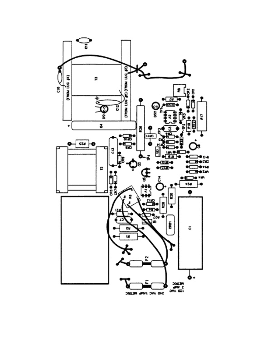
a. Before turning on the unit, do the following:
(1) Turn the R8 potentiometer completely clockwise. Refer to figure 1-3.
(2) Connect the BIPOLAR outputs to the electrosurgical tester.
b. Turn the unit on.
(1) Set the intensity knob (maximum setting).
(2)
Activate
the
unit and slowly adjust the R8 potentiometer counterclockwise
for an output of 30w.
(3) Slowly turn the intensity knob back to zero. The output should decrease
evenly. If the output does not decrease evenly turn OFF the unit and repeat the complete
procedure by starting again at paragraph 1-9a.
(4) Verify BIPOLAR, HIGH, and LOW output per paragraphs 1-8a through c.
MD0363 1-10
Figure 1-3. Circuit board layout.

MD0363 1-11
c. When the unit is calibrated and safety tested to manufacturer's specifications
(see paragraph 1-10), return it to service.
1-10. SPECIFICATIONS
In addition to the above calibration settings, you also need to verify the following
Birtcher Hyfrecator specifications. Use the procedures in the manufacturer's operations
and service manual to ensure the unit is safe to operate. Refer to figure 1-4.
CHARACTERISTIC
SPECIFICATION
Leakage
With third wire (ground) open: 50
microamperes maximum.
Power Input Requirements
733 SW and 733 FS, 120vac, 50-60 Hz
(Hertz), 125w.
733 ASW and 733 AFS, 240vac, 50-60
Hz), 125w.
Output Wave Shape
Damped Sinusoidal. Damped to the point
of being effectively one pulse under load.
Open circuit voltage BIPOLAR 1500vp-p
(voltage peak to peak) maximum. High
7000vp-p maximum.
Regulation
+ 30 percent full power, 500 ohm load, line
voltage 100-130vac.
Duty Cycle
Normal type procedure: rated at 25
percent with 10 seconds on, 30 seconds
off.
Figure 1-4. Birtcher hyfrecator specifications.

MD0363 1-12
EXERCISES, LESSON 1
INSTRUCTIONS: Answer the following exercises by marking the lettered response that
best answers the question or best completes the sentence.
After you have answered all of the exercises, turn to "Solutions to Exercises" at the
end of the lesson and check your answers. For each exercise answered incorrectly,
reread the lesson material referenced with the solution.
1. You turned the control dial from the OFF to ON position. Which indicator lights up on
the Birtcher Hyfrecator?
a. Circuit pilot light.
b.
ON/OFF
pilot
light.
c.
Low
battery
light.
d.
Control
light.
2. Which technique configuration do you use to deliver power for coagulation from one
terminal of an ungrounded BIPOLAR output of a return through the indifferent plate?
a.
Monoterminal
configuration.
b.
Monopolar
configuration.
c.
Tripolar
configuration.
d.
Bipolar
configuration.
3. Unless you perform general safety precautions, you can receive severe burns from
the Birtcher Hyfrecator because its output can exceed:
a.
4,000v.
b.
5,000v.
c.
6,000v.
d.
7,000v.

MD0363 1-13
4. You are following general safety precautions while working on the hyfrecator. If you
do not remove the F1 fuse, you:
a. Connect the hand piece.
b. Depress the hand switch.
c. Connect the foot switch cables.
d. Turn down the power to a safe level.
5. Which of the following do you perform as part of the quarterly PMCS procedures?
a. Remove the printed circuit board.
b. Measure for voltage integrity.
c. Remove the operative assembly.
d. Perform an operational checkout.
6. You are performing an operational checkout. You should hold the needle electrode
two to three millimeters away from which item?
a.
Wet
sponge.
b.
Hand
switch.
c.
Switch
control
cord.
d.
LOW
output
receptacle.
7. The specification for both BIPOLAR outputs is:
a.
20
+ 2 watts (500 ohm load).
b.
30
+ 2 watts (500 ohm load).
c.
30
+ 4 watts (500 ohm load).
d.
40
+ 2 watts (500 ohm load).

MD0363 1-14
8. You are calibrating the BIPOLAR outputs. Before turning the unit on:
a. Slowly adjust the R8 potentiometer counterclockwise for an output of 30 watts.
b. Connect the BIPOLAR outputs to the electrosurgical tester.
c. Slowly turn the intensity knob back to zero.
d. Set the intensity knob (maximum setting).
Check Your Answers on Next Page

MD0363 1-15
SOLUTIONS TO EXERCISES, LESSON 1
1. b
(para 1-3g)
2. b
(para 1-4b)
3. d
(para 1-6)
4. d
(para 1-6a)
5. d
(para 1-7)
6. a
(para 1-7c(7))
7. b
(para 1-8a(6))
8. b
(para 1-9a(2))
End of Lesson 1

MD0363 2-1
LESSON ASSIGNMENT
LESSON 2
Malfunctions and Defective Modules.
TEXT ASSIGNMENT
Paragraphs 2-1 through 2-6.
TASKS TAUGHT
Isolate malfunctions to module level in the electrosurgical
apparatus.
Remove and replace defective modules of the
electrosurgical
apparatus.
LESSON OBJECTIVES
When you have completed this lesson, you should be
able to:
2-1.
Identify
the
functions of the electrosurgical
apparatus
circuit.
2-2.
Identify the equipment used to troubleshooting
malfunctions.
2-3.
Identify the procedures to use when
troubleshooting a malfunction.
2-4.
Identify the procedures for removing and
replacing a defective buzzer, a faulty hand piece,
and a malfunctioning printed circuit board.
SUGGESTION
Work the lesson exercises at the end of this lesson
before beginning the next lesson. These exercises will
help you accomplish the lesson objectives.

MD0363 2-2
LESSON 2
MALFUNCTIONS AND DEFECTIVE MODULES
Section I. ISOLATE MALFUNCTIONS TO MODULE LEVEL IN
ELECTROSURGICAL APPARATUS
2-1. THE
CIRCUIT
Knowing the functions of the circuit will help you isolate the causes of malfunctions.
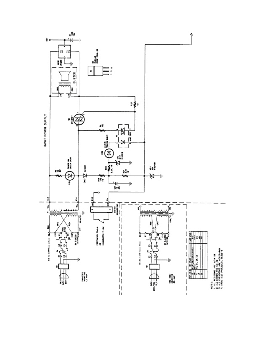
a. General. A2 is a multivibrator (mv) with a hysteresis voltage of 10v and 3v
shown at TP2. Refer to figure 2-1.
(1) TP1 is the wave shape of the charge and discharge of the capacitor at the
inverting input of A2 resulting in the switching of the mv. TP1, charging time going positive
("on" time of the output transistor) and discharge time going negative ("off" time of the
output transistor) is varied by the front panel power level control knob. During the "on"
time, TP3 is high and Q4 output is saturated on.
(2) The current through the output transformer primary inductance increases
linearly by I = ET/L (current = voltage X time/inductance) and the energy stored at any time
is J = 1/2 LI
2
(joule = 1/2 inductance X current squared). The power of P = 1/2 LI
2
x Rate
of Storage and Discharge (power = 1/2 inductance X current squared X rate of storage
and discharge). When Q4 is turned off, the energy in T3 primary resonates with C13
producing a damped signal wave into an output load.
b. Circuit Description.
(1) Functions of the level control and rate generator.
(a)
Comparator
amplifier A2 functions as a pulse repetition generator. Its
pulse width and rate is varied with the potentiometer R6 controlling the final power output.
(b) A2 is a self-starting mv. When the power is applied, pin 7 of A2 (the
collector output) is high and through CR1 and R6 charges C3 to pin 3 of A2 TP1.
(c)
The
non-inverting differential input pin 2 A2 is clamped to +10v
through CR3 to zener VR2.
(d) When pin 3 (voltage on C3) reaches +10v, the comparator changes
state, and pin 7 switches to low. Pin 2 is at the voltage division of R13 and R14 (3v). C3
discharges through CR2, R6, R8, and R7 until this voltage at pin 3 is lower than 3v and A2
changes state again. This completes the multivibrator cycle.
MD0363 2-3
Figure 2-1. Hyfrecator Model 733 wiring diagram.
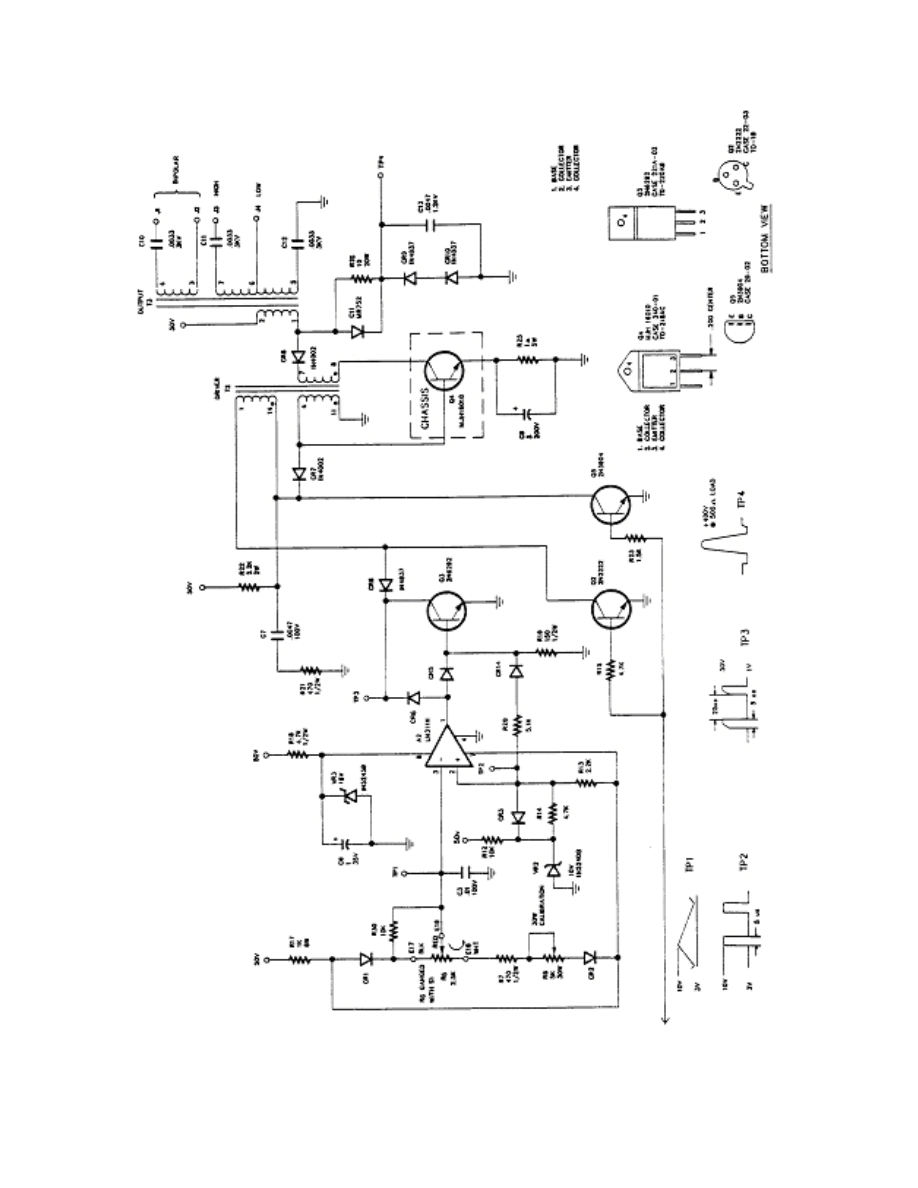
MD0363 2-4
Figure 2-1. Hyfrecator Model 733 wiring diagram (concluded).

MD0363 2-5
(2) Functions of the driver.
(a) The collector of the power driver Q3 is in phase with the collector of
the transistor (pin 7) on mv A2.
(b) Q2, Q3, and Q5 initiate the on and off drive to the power output stage
Q4.
(3) Functions of the output.
(a) When Q3 is turned off by the drive from mv A2 - pin 1, the magnetic
energy stored in T2 (winding pins 1 and 14) is induced into T2 (winding pins 4 and 11)
switching the output transistor Q4 to on.
(b) The current through Q4 now stores the magnetic energy in T3
(winding pins 1 and 2). With Q4 on, the current increases with time. When Q4 is turned
off, T3 (winding pins 1 and 2) resonates with C13.
(c) The result is a damped sinusoid wave shape. The energy is coupled
by secondary windings to generate output power. The wave shape damping varies with
the particular output load. With average physiological loads, one or two high amplitude
cycles exist.
(4)
Functions
of the power supply.
(a) The power supply is an unregulated +50 volts and regulated 5, 10,
and 15v by zener diodes.
(b)
The
secondary
rectification is by a full wave bridge.
(5) Functions of the switch.
(a) The output power can be switched on and off by the foot switch or
hand switch.
(b) Closing E21 to ground turns off Q2 and Q5, and increases light
emitting diode (led) current to optically excite the silicon detector chip to drive the gate of
triac Q1. With Q2 off, A2 functions as a multivibrator.
(6)
How
to generate sound. Audio is generated by pulsing the solenoid
(buzzer) on and off from the ac secondary voltage.
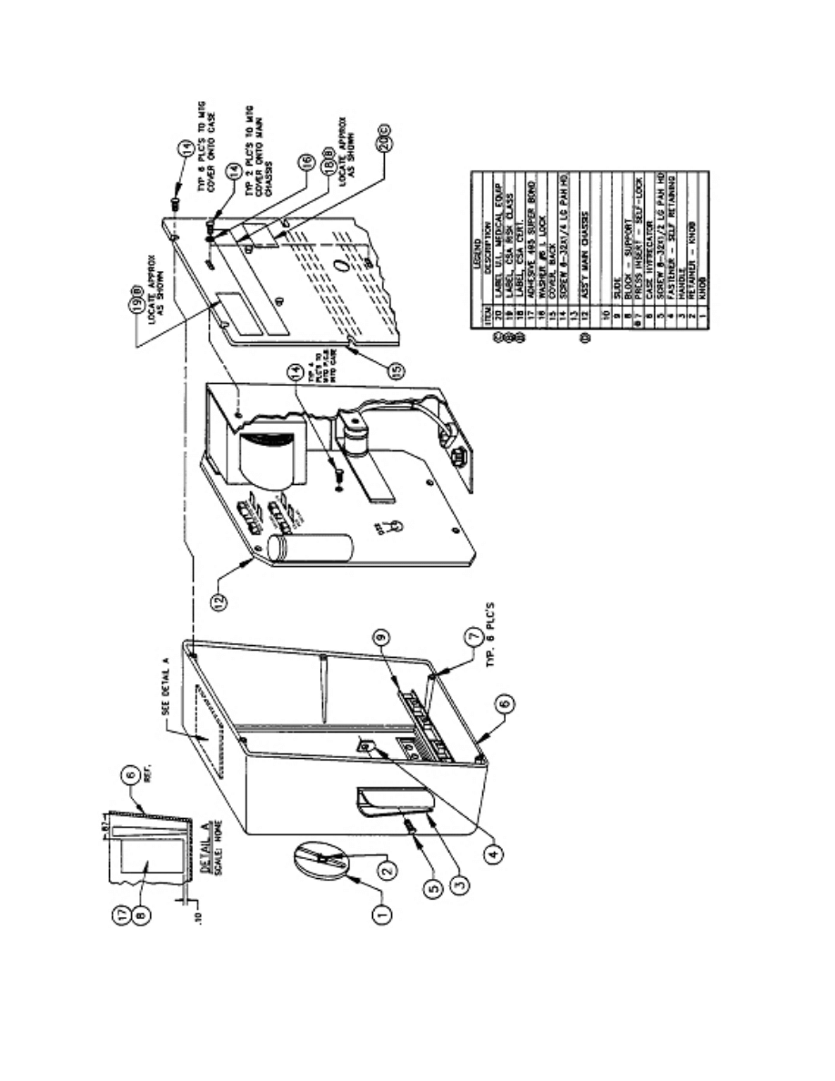
c. Access
the
Unit. You can access the entire printed circuit board (pcb) and
operative assembly by removing the back screws, 4 pcb screws, and the control knob.
Refer to figure 2-2.
MD0363 2-6
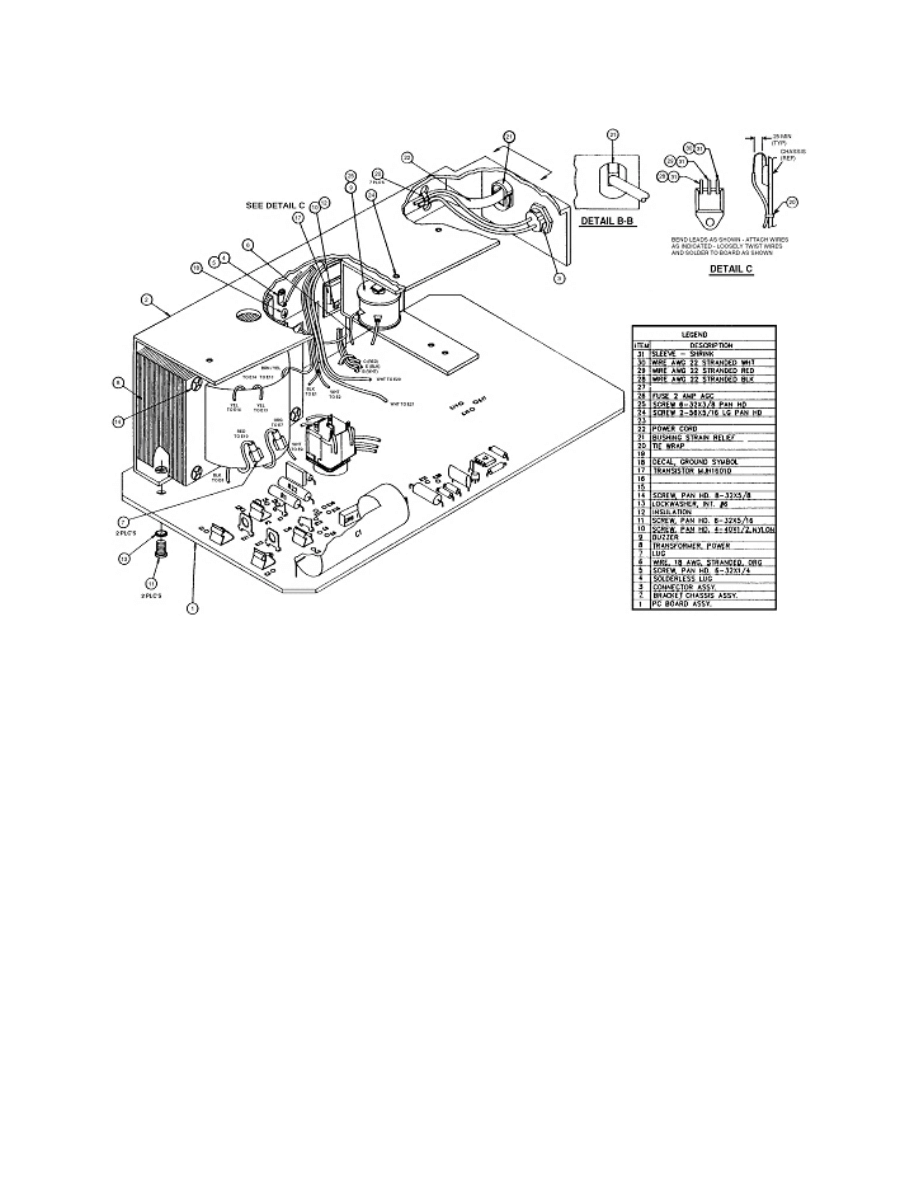
Figure 2-2. Hyfrecator final assembly (110v 50 cycle main housing assembly).

MD0363 2-7
2-2. TROUBLESHOOTING PROCEDURES
Use the following troubleshooting techniques to identify the causes of malfunctions.
a. Equipment. You need the following equipment to troubleshoot the hyfrecator:
(1)
Volt-ohm
meter.
(2)
Oscilloscope.
(3) Electrosurgical test set.
b. Troubleshooting Guideline. Refer to the Hyfrecator Troubleshooting
Guideline in the appendix. Use it to isolate malfunctions. The guideline consists of three
columns:
(1)
Symptom. Lists symptom you are observing with the malfunctioning unit.
(2)
Probable
Cause. Indicates, in priority order, the most likely causes for the
symptom under discussion.
(3)
Corrective
Action. Lists the proper corrective action to take to repair the
malfunction for the probable cause indicated.
c. Troubleshooting a Malfunctioning Printed Circuit Board . Refer to the Hyfrecator
Troubleshooting Guideline in the appendix, Symptom number six.
(1) Remove the active Q4 devices.
(a) Measure for voltage integrity.
(b) Check test points TP1 through TP3 for correct operation. Refer to
figure 1-3.
(c)
Insert
the
output transistor for operation and final calibration.
(2) Critically inspect test point TP4 for a heavily damped sinusoid. This
damping occurs whether the output is loaded or open circuited. With a dial setting of half
scale, and the output loaded, the first sinusoid completed is about 400v peak. The second
sinusoid is about 100v peak. With an unloaded output, the damping of the wave shape
goes virtually to zero volts in 5 cycles.
(3) If the above conditions are not met on full power output (30w bipolar),
check transistors Q5, Q4, and Q3 in that order for a possible shorted condition. Check
CR9 and CR14 if needed.
MD0363 2-8
d.
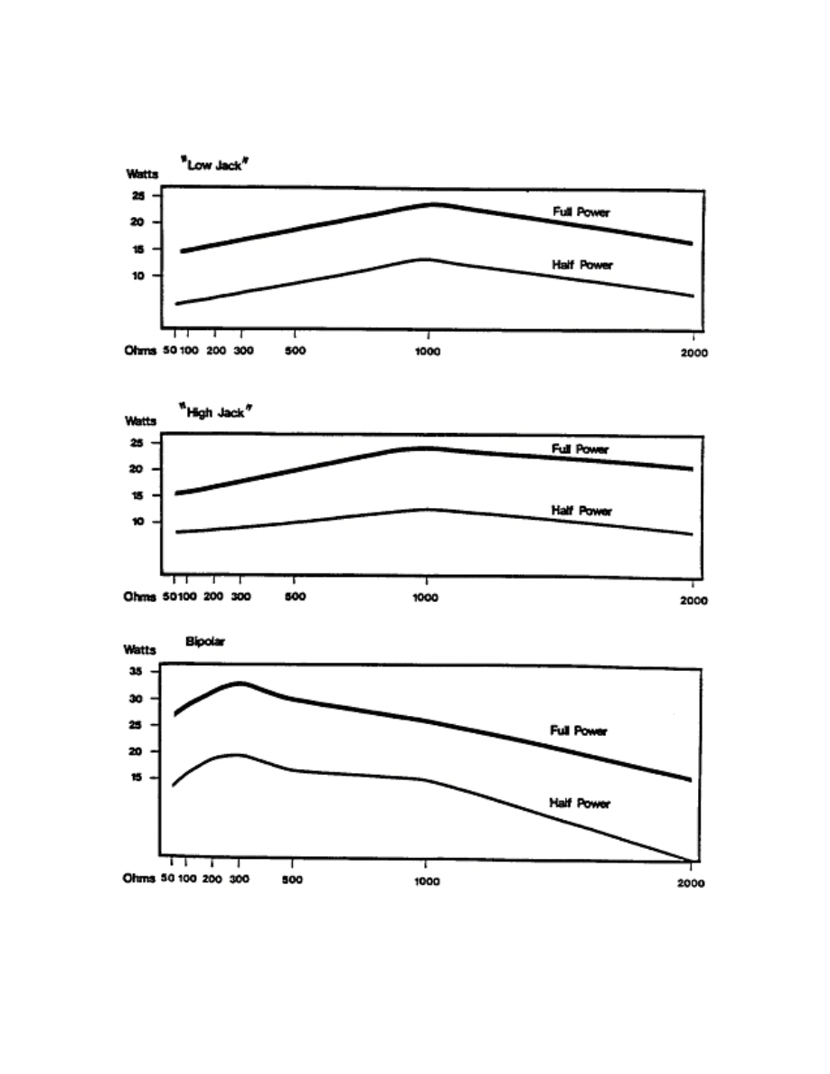
Test Points and Locations. When testing power outputs, you should see, on
an oscilloscope, the signals shown in figures 2-3 through 2-5.
Figure 2-3. Output power load variation.
MD0363 2-9
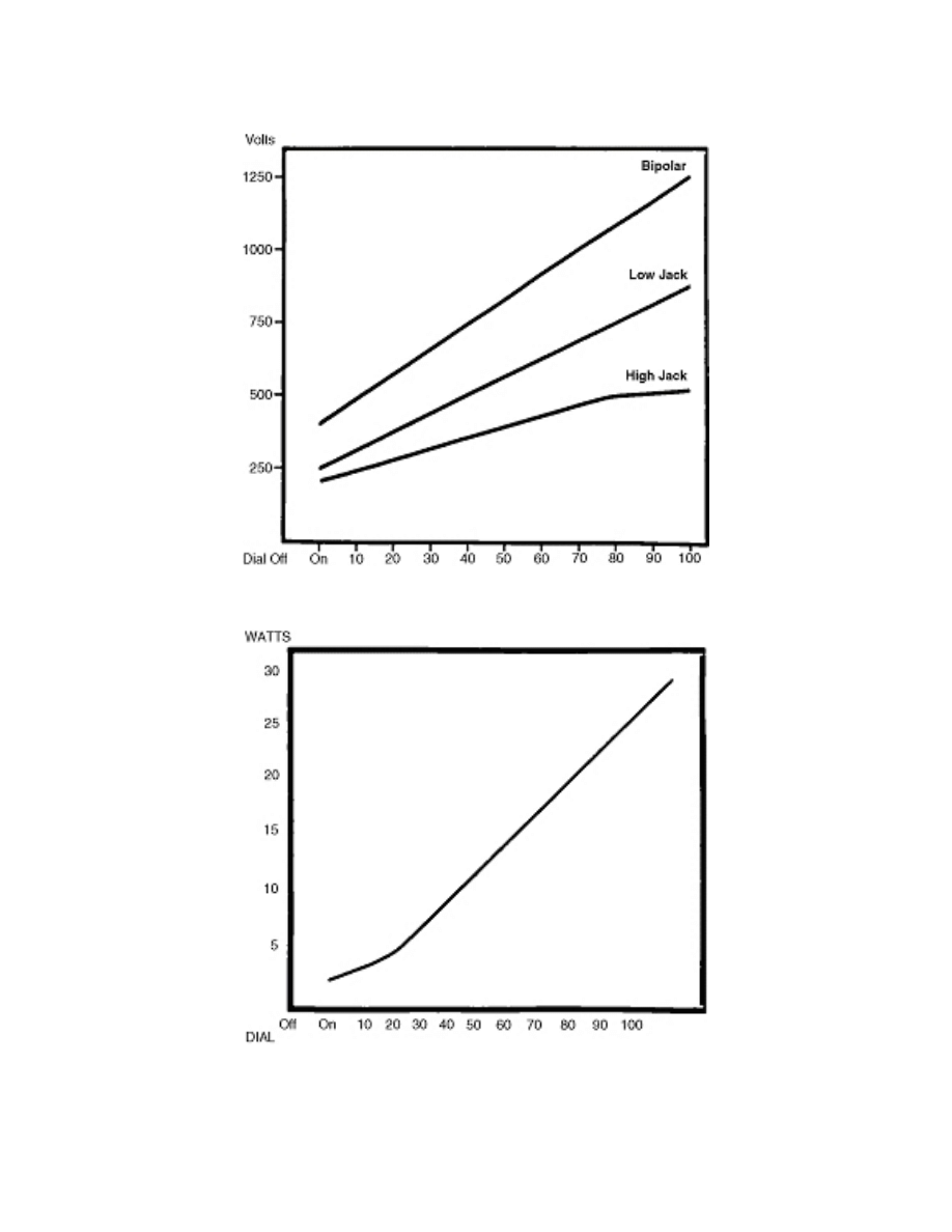
Figure 2-4. Voltage output peak to peak versus dial position at 300 ohms.
Figure 2-5. Power output (bipolar) versus dial position at 500 ohms.

MD0363 2-10
Section II. REMOVE AND REPLACE DEFECTIVE MODULES OF
ELECTROSURGICAL APPARATUS
2-3. LOCATIONS
OF
PARTS
The modules included in this lesson represent a portion of the total number of
modules in this piece of equipment. The skills required to remove and repair or replace a
portion of the modules are transferable to removing and repairing or replacing all modules.
Study the location of the modules and components in figure 2-6, Main chassis assembly
(110v).
2-4.
REMOVE AND REPLACE A DEFECTIVE BUZZER
You have isolated a malfunction to a defective buzzer. Refer to the steps below and
figures 2-1 and 2-6 to replace it.
a. Turn off the unit.
b. Remove power from the unit.
c. Remove the back six screws.
d. Remove the back cover.
(1) Remove the intensity knob.
(2)
Remove
the printed circuit board (PCB) assembly.
e. Remove and replace the buzzer.
f. Replace the back cover and screws.
g. Perform an operational checkout (Refer to paragraphs 1-7c(1) through (9).
h. Return the unit to service.
MD0363 2-11
Figure 2-6. Main chassis assembly (110v).
2-5.
REMOVE AND REPLACE FAULTY HAND PIECE
You have isolated a malfunction to a faulty hand piece. Refer to figures 1-1
and 2-1.
a. Turn off the unit.
b. Remove power from the unit.
c. Remove the hand piece.
d.
Replace
the
hand
piece with a new one.
e. Restore power to the unit.
f. Perform an operational checkout. Refer to paragraphs 1-7c(1) through (9).
g. Return the unit to service.

MD0363 2-12
2-6.
REMOVE AND REPLACE A MALFUNCTIONING PRINTED CIRCUIT BOARD
You have isolated a malfunctioning PCB. Refer to figures 1-3, 2-2, and 2-6.
a. Turn off the unit.
b. Remove power from the unit.
c. Unplug the foot switch from the unit.
d.
Unplug
the
hand piece from the unit.
e. Remove the back six screws.
f. Remove the back cover.
g. Remove the intensity knob.
h. Access the PCB.
i. Remove and replace the PCB. Mark all wires and connectors so that they can be
properly reconnected (figure 2-6).
j.
Reassemble
the
unit.
k. Perform an operational checkout. Refer to paragraphs 1-7c(1) through (9).
l. Perform calibration tests (refer to paragraphs 1-9a, b), safety test to
manufacturer's specifications, and return the unit to service.

MD0363 2-13
EXERCISES, LESSON 2
INSTRUCTIONS: Answer the following exercises by marking the lettered response that
best answers the question or best completes the sentence.
After you have answered all of the exercises, turn to "Solutions to Exercises" at the
end of the lesson and check your answers. For each exercise answered incorrectly,
reread the lesson material referenced with the solution.
1. The A2 multivibrator has a hysteresis voltage of:
a. 10v and 3v.
b. 10v and 5v.
c. 12v and 10v.
d. 24v and 15v.
2. Which circuit functions as a pulse repetition generator?
a.
Driver.
b.
Output.
c.
Power
supply.
d. Comparator amplifier A2.
3. Refer to the Hyfrecator Troubleshooting Guideline in the appendix. If the unit will not
coagulate, and you have no ACTIVE light with either the foot switch or hand switch,
which of the following is a probable cause?
a. DS1 is open.
b.
Open
buzzer.
c.
Fuse
F1 is open.
d. Bad printed circuit board.

MD0363 2-14
4. You are removing and replacing a defective buzzer. After turning off the unit and
removing power from the unit, the next step is which of the following?
a. Remove the hand piece and/or the foot switch.
b. Remove the back six screws.
c. Remove and replace the buzzer.
d. Replace the back cover and screws.
5. You have isolated a malfunction to a faulty hand piece. After turning off the unit and
removing the power from the unit, you should next:
a. Remove the hand piece.
b. Restore power to the unit.
c.
Replace
the
hand
piece with a new one.
d. Perform an operational checkout.
6. You have isolated a malfunction to the printed circuit board. What is the last step in
the removing and replacing process for the pcb?
a.
Unplug
the
hand piece from the unit.
b. Replace the printed circuit board.
c.
Perform
operational checkout.
d. Perform calibration tests.
Check Your Answers on Next Page

MD0363 2-15
SOLUTIONS TO EXERCISES, LESSON 2
1. a
(para 2-1a)
2. d
(para 2-1b(1)(a))
3. d
(Appendix, number six)
4. b
(para 2-4c)
5. a
(para 2-5c)
6. d
(para 2-6k)
End of Lesson 2

MD0363 A-1
APPENDIX
HYFRECATOR TROUBLESHOOTING GUIDELINE
SYMPTOM PROBABLE CAUSE
CORRECTIVE ACTION
1. The unit will not energize.
Unit not plugged in.
Fuse F1 or F2 open.
Plug in to 110vac grounded
outlet.
Replace.
2. Power on light does not
energize.
DS1 is open.
Replace.
3. Unit coagulates, but the
buzzer does not sound.
Open lead to buzzer.
Open buzzer.
Reconnect.
Replace.
4. Unit will not coagulate,
buzzer and active (yellow)
light operate.
Bad hand piece.
Replace.
5. Unit coagulates with hand
switch, but not with foot
switch.
Bad foot switch.
Replace.
6. Unit will not coagulate, no
ACTIVE (yellow) light or
buzzer with either foot switch
or hand switch.
Bad printed circuit board or
component.
Use TP1 through TP$ to
isolate faulty area, then
locate and replace faulty
component
OR
Replace printed circuit
board.
End of Appendix
Document Outline
- DEVELOPMENT
- ADMINISTRATION
- TABLE OF CONTENTS
- INTRODUCTION
- LESSON 1
- LESSON 2
- APPENDIX
Wyszukiwarka
Podobne podstrony:
atex05242a simple electrical apparatusrev1 VK5POASNPOS5HGBZGYQNNVB7E2FFOSFPZ5V6JKA
US Patent 649,621 Apparatus For Transmission Of Electrical Energy
US Patent 577,670 Apparatus For Producing Electric Currents Of High Frequency
British Patent 6,481 Improvements relating to the Electrical Transmission of Power and to Apparatus
Canadian Patent 30,172 Improvements in Methods of and Apparatus for Converting and Distributing Elec
British Patent 2,812 Improvements in Methods of and Apparatus for the Generation of Electric Current
Canadian Patent 29,537 Improvements in Methods of and Apparatus for the Electrical Transmission of P
US Patent 568,180 Apparatus For Producing Electrical Currents Of High Frequency
British Patent 8,575 Improved Methods of and Apparatus for Generating and Utilizing Electric Energy
British Patent 6,502 Improvements relating to the Generation and Distribution of Electric Currents a
Electrolux sprzęt
Biomass Fired Superheater for more Efficient Electr Generation From WasteIncinerationPlants025bm 422
General Electric
Rodzaje pracy silników elektrycznych, 04. 01. ELECTRICAL, 07. Elektryka publikacje, 07. Electrical M
Elektor Electronics No 10 10 2011
ElectronIII
Electrolysis (8)
JCE1965p0433 melting point apparatus
Electronics 4 Systems and procedures S
więcej podobnych podstron