
arXiv:1402.6461v1 [cs.CR] 26 Feb 2014
Formal verification of a software countermeasure against instruction
skip attacks
Nicolas Moro
1,2
, Karine Heydemann
1
, Emmanuelle Encrenaz
1
, and Bruno Robisson
2
1
Sorbonne Universit´es, UPMC Univ Paris 06, UMR 7606, LIP6, 75005 Paris, France
firstname.lastname@lip6.fr
2
CEA, CEA-Tech PACA, LSAS, 13541 Gardanne, France
firstname.lastname@cea.fr
February 27, 2014
Abstract
Fault attacks against embedded circuits enabled to define many new attack paths against secure
circuits. Every attack path relies on a specific fault model which defines the type of faults that the
attacker can perform. On embedded processors, a fault model consisting in an assembly instruction skip
can be very useful for an attacker and has been obtained by using several fault injection means. To avoid
this threat, some countermeasure schemes which rely on temporal redundancy have been proposed.
Nevertheless, double fault injection in a long enough time interval is practical and can bypass those
countermeasure schemes. Some fine-grained countermeasure schemes have also been proposed for specific
instructions. However, to the best of our knowledge, no approach that enables to secure a generic assembly
program in order to make it fault-tolerant to instruction skip attacks has been formally proven yet. In
this paper, we provide a fault-tolerant replacement sequence for almost all the instructions of the Thumb-
2 instruction set and provide a formal verification for this fault tolerance. This simple transformation
enables to add a reasonably good security level to an embedded program and makes practical fault
injection attacks much harder to achieve.
1
Introduction
Physical attacks were introduced in the late 1990s as a new way to break cryptosystems. Unlike classical
cryptanalysis, they use some weaknesses in the cryptosystems’ implementations as a way to break them.
Among them, faults attacks were introduced in 1997 by Boneh et al. [
]. In this class of attacks, attackers
try to modify a circuit’s environment in order to change its behaviour or induce faults into its computations
[
]. This attack principle was first introduced against cryptographic circuits but can be used against a
larger set of embedded circuits. Many physical means can be used to induce such faults: laser shots [
clock glitches [
] or electromagnetic glitches [
Among fault attacks, three subclasses can be distinguished: differential fault analysis, safe error and
algorithm modifications. Differential fault analysis (DFA) aims at retrieving some ciphering keys by com-
paring correct ciphertexts with ciphertexts obtained from a faulted encryption [
]. Safe-error attacks are
based on the fact that a fault injection may have or not have an impact on the output [
]. Finally, algorithm
modifications target an embedded processor and aim at injecting faults into an embedded program’s control
flow [
Those attack schemes rely on an attacker’s fault model which defines the set of faults an attacker can
perform [
]. As a consequence, countermeasure schemes must take this fault model aspect into account.
On microcontrollers and embedded processors, the fault model in which an attacker can skip an assembly
The final publication is available at Springer via http://dx.doi.org/10.1007/s13389-014-0077-7
1

instruction has been observed on different architectures [
] and for different fault injection means [
]. As a consequence, this fault model is a realistic threat for an embedded program.
In this paper, we consider this instruction skip fault model and propose a countermeasure scheme that
enables to secure any assembly code against instruction skip faults. Some countermeasures based on multiple
executions of a function have already been proposed and can theoretically handle this issue [
]. However, this
kind of high granularity temporal redundancy is vulnerable to multiple fault attacks. Even with commonly-
used low-cost fault injection means, a high temporal accuracy can be obtained by an attacker, and performing
the same fault injection on several executions of an algorithm is practical [
]. On the contrary, performing
faults on two instructions separated by a few clock cycles is significantly harder [
] while still possible.
Indeed, it requires a much more costly fault injection equipment and very high synchronization capabilities.
It is then not yet considered as a realistic threat.
The securing approach proposed in this paper uses an instruction-scale temporal redundancy to ensure
a fault-tolerant execution of an embedded program. It is based on the statement that performing two faults
on two instructions separated by few clock cycles is hardly feasible. A fault-tolerant replacement sequence
for most of the instructions of the whole Thumb-2 instruction set has been designed. We also show how to
formally prove the fault tolerance of replacement sequences by using a model-checking tool.
By using such a fine-grained redundancy scheme, it is then possible to strengthen most assembly programs
against fault attacks without any specific knowledge about the program itself. In the experimental results,
we evaluate the overhead induced by fault tolerance and show that it can be reduced by only applying this
countermeasure scheme to the sensitive parts of an implementation.
The rest of this paper is organized as follows. Section
introduces our fault model and gives details about
some related research papers. Section
introduces our countermeasure scheme and details our replacement
sequences. Section
explains the approach we use for the formal verification. Finally, section
evaluates
the efficiency of our countermeasure scheme on several implementations.
2
Related works and fault model
This section is dedicated to related works. First, fault models are discussed in section
. Countermeasure
schemes that have previously been proposed are addressed in section
. Section
presents some related
research papers on formal verification.
2.1
Fault model
On embedded processors, a fault model in which an attacker can skip an assembly instruction or equivalently
replace it by a nop has been observed on several architectures and for several fault injection means [
]. On a
8-bit AVR microcontroller, Schmidt et al. [
] obtained instruction skip effects by using
clock glitches. Dehbaoui et al. obtained the same kind of effects on another 8-bit AVR microcontroller by
using electromagnetic glitches [
]. On a 32-bit ARM9 processor, Barenghi et al. obtained some instruction
skip effects by using voltage glitches. On a more recent 32-bit ARM Cortex-M3 processor, Trichina et al.
were able to perform instruction skips by using laser shots [
]. Moreover, this fault model has also been
used as a basis for several cryptanalytic attacks [
]. As a consequence, it is considered as a common fault
model an attacker may be able to perform [
A more generic fault model is the instruction replacement model, in which nop replacements correspond
to one possible case. In some previous experiments on an ARM Cortex-M3 processor by using electromag-
netic glitches, we have observed a corruption of the instructions binary encodings during the bus transfers
[
] leading to such instruction replacements. Actually, instruction skips correspond to specific cases of
instruction replacements: replacing an instruction by another one that does not affect any useful register
has the same effect as a nop replacement and so is equivalent to an instruction skip. Many injection means
enable to perform instruction replacement attacks [
]. Nevertheless, even with very accurate fault
injection means, being able to precisely control an instruction replacement is a very tough task and, to the
best of our knowledge, no practical attack based on such a fault model has been published yet.
As a conclusion, we consider in this paper the potentially harmful fault model in which an attacker is
able to skip a single instruction.
2

2.2
Countermeasure schemes
Several countermeasures schemes have been defined to protect embedded processor architectures against
specific fault models. At hardware level, many countermeasures have been proposed. As an example,
Nguyen et al. [
] propose to use integrity checks to ensure that no instruction replacement took place.
Software-only countermeasure schemes, which aim at protecting the assembly code, are more flexible and
avoid any modification of the hardware. Against fault attacks, the most common software fault detection
approach relies on function-level temporal redundancy [
]. For example, this principle applied to a crypto-
graphic implementation can be achieved by calling twice the same encryption algorithm on the same input
and then comparing the outputs. For encryption algorithms, an alternative way is to call the deciphering
algorithm on the output of an encryption and to compare its output with the initial input. These approaches
enable fault detection and involves doubling the execution time of the algorithm. Triplication approaches
with voting enabling fault tolerance at the price of tripling the execution time of the whole algorithm have
also been proposed [
At algorithm level, in [
], Medwed et al. propose a generic approach based on the use of specific algebraic
structures named AN+B codes. Their approach enables to protect both the control and data flow.
At assembly level, in [
], Barenghi et al. propose three countermeasure schemes based on instruction
duplication, instruction triplication and parity checking. Their approach ensures a fault detection for a
small number of instructions against instruction skip or transient data corruption fault models. Our scheme
enables a fault tolerance only against the instruction skip fault model but for almost all the instructions
of the considered instruction set. Moreover, our countermeasure scheme has been formally proven fault
tolerant.
2.3
Formal verification of software countermeasures
Formal methods and formal verification tools have been used for cryptographic protocols’ verification of to
check that an implementation could meet the Common Criteria security specifications [
]. However, to the
best of our knowledge, very few formal verification approaches to check the correctness of software counter-
measure schemes against fault attacks have been proposed yet. One of the most significant contributions has
been proposed by Christofi et al. [
]. Their approach aims at performing a source code level verification of
the effectiveness of a countermeasure scheme on a CRT-RSA implementation by using the Frama-C program
analyzer. In this paper, we formally prove all our proposed countermeasures against an instruction skip fault
model at assembly level. Another more recent contribution of a formal methodology at algorithm level has
been proposed by Rauzy et al. [
]. In their scheme, an attacker can induce faults in the data flow of a
target implementation described in a high-level language. This scheme enables them to detect unnecessary
countermeasures or possible flaws on several CRT-RSA implementations.
3
Countermeasure scheme
The proposed countermeasure scheme aims at ensuring a fault-tolerant execution of an assembly code against
instruction skip faults. The approach we propose relies on providing a formally proven fault-tolerant re-
placement sequence for almost all the assembly instructions of a whole instruction set. We chose the ARM
Thumb-2 instruction set [
] since ARM is a widely used target architecture for embedded processors. In
this section, we give some details about the considered instruction set and present some of the replacement
sequences we have defined for each instruction. This fine-grained redundancy scheme enables to strengthen
most assembly codes against fault attacks without any specific knowledge about them.
3.1
The Thumb-2 instruction set
Thumb-2 is actually the successor to both ARM and Thumb instruction sets. Thumb-2 is a variable-length
instruction set since it extends the 16-bit Thumb instruction set with some 32-bit instructions. Thus, 16
and 32-bit instructions can be mixed in a single program to combine both code density and performance.
However, unlike the ARM instruction set, most 32-bit Thumb-2 instruction do not support direct conditional
execution. To achieve such a conditional execution, a new If-Then (it) instruction has been introduced.
3
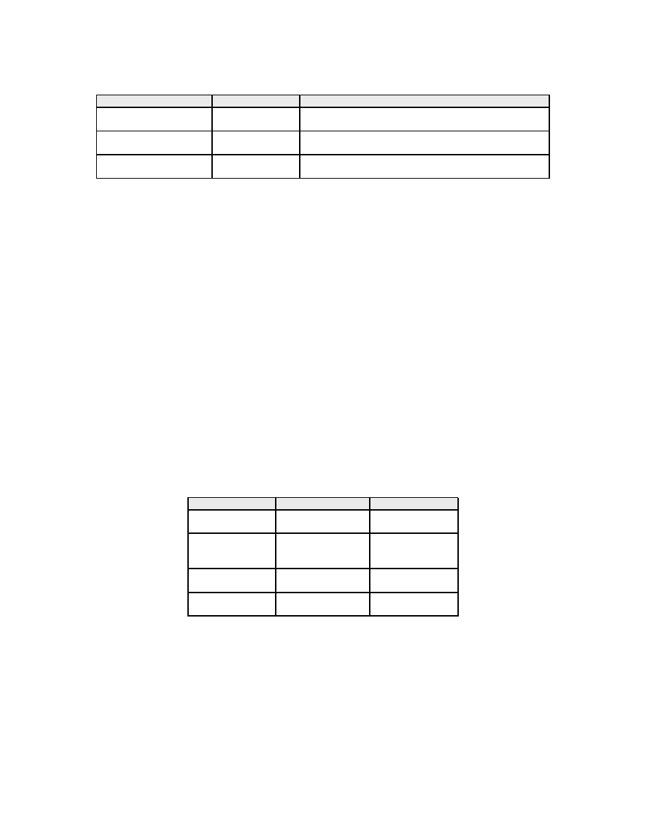
Table 1: Instruction classes in the Thumb-2 instruction set
Instruction class
Examples
Replacement scheme
Idempotent instructions
mov r1,r8
Instruction duplication
add r3,r1,r2
Separable instructions
add r1,r1,#1
Use of extra registers and
push
{r4,r5,r6}
decomposition into an idempotent instruction sequence
Specific instructions
bl <function>
Replacement sequence specific to each instruction
it
blocks
Moreover, some constant shifts can be applied to one operand of some instructions. Those shifts are :
lsl
(logical shift left), lsr (logical shift right), asr (arithmetic shift right), ror (rotate right) and rrx
(rotate right one bit with extend). The Thumb-2 instruction set was first introduced with the ARMv6-T2
architecture and is now the standard instruction set for ARMv7 architectures.
3.2
Instruction classes
We have defined a fault-tolerant replacement sequence for each instruction and each encoding of the Thumb-2
instruction set. This instruction set contains 151 instructions, and each instruction has up to four different
encodings. For many instructions, the replacement sequence is very simple. However, this sequence can
become much more complex for some specific instructions. According to the replacement sequences found,
the instructions in the Thumb-2 instruction set can be divided into three classes. Every class is associated
to one kind of replacement sequence. These three classes are summarized in Table
The first class is composed of idempotent instructions which only need to be duplicated to provide
fault tolerance. The second class gathers the instructions that are not idempotent but can be replaced by
an equivalent sequence of idempotent instructions. The third class gathers some specific instructions that
cannot easily be replaced by a list of idempotent instructions but for which a specific replacement sequence is
possible. This last class also contains the instructions for which no replacement sequence that ensures fault
tolerance and correct execution in any case can be provided. The solution for these instructions is either to
avoid the compiler to use them or to use a fault detection approach. The following section gives more details
about those classes. Moreover, it provides some examples of replacement sequences for every class.
Table 2: Replacement sequences for some idempotent instructions
Instruction
Description
Replacement
mov r1,r8
Copies r8 into r1
mov r1,r8
mov r1,r8
ldr r1,[r8,r2]
Loads the value
ldr r1,[r8,r2]
at the address
ldr r1,[r8,r2]
r8+r2
into r1
str r3,[r2,#10]
Stores r3 at
str r3,[r2,#10]
the address r2+10
str r3,[r2,#10]
add r3,r1,r2
Puts r1+r2 into r3
add r3,r1,r2
add r3,r1,r2
3.3
Individual instruction replacement sequences
3.3.1
Idempotent instructions
Idempotent instructions are the instructions that have the same effect when executed once or several times.
If all the source operands are different from the destination operands, and if the value written into the
destination operands does not depend on the instruction’s location in the code, then the instruction is said
to be idempotent. For such instructions, the countermeasure consists in a simple instruction duplication.
The overhead for such a duplication is twofold: an overhead which equals the instruction size in terms of
4

code size and a performance overhead that is equal to the execution time of the instruction. Table
gives
some examples of idempotent instructions and their associated replacement sequence.
3.3.2
Separable instructions
Listing 1: Replacement sequence for the non idempotent add r1, r1, r3 instruction
1
; we assume rx is an available register
2
mov
rx
,
r 1
3
mov
rx
,
r 1
4
add
r1
,
rx
,
r 3
5
add
r1
,
rx
,
r 3
In the considered instruction set, some instructions are not idempotent but can be rewritten by a se-
quence of idempotent instructions whose execution gives the same result. Once this rewritting is performed,
each idempotent instruction of the replacement sequence can then be duplicated. This class gathers the
instructions whose destination register is also a source register. To replace these instructions by a sequence
of idempotent instructions, some extra registers have to be used. These registers have to be available at this
location in the code: any dead register can be used
. If no dead register is available, the stack can be used
to temporarily store the value in a register.
Simple separable instructions
Listing
shows the replacement sequence for an add r1, r1, r3 in-
struction. For this class of instructions, the overhead cost brought by our countermeasure scheme depends
on the instruction to replace. There is an overhead cost in code size, performance and register pressure (since
the replacement sequence needs some extra registers). For the add r1, r1, r3 instruction example, one
extra register is needed. Moreover, 4 instructions are required instead of 1 and the overhead cost in terms
of code size is between 6 and 10 bytes (depending on the encoding used for the initial and the replacement
instructions).
Stack manipulation instructions
Some memory access instructions can update the address register
before or after (stmdb
/ldmia
) a memory access. As a consequence, this address register is both a source
and a destination register for such an instruction. This is notably the case of the stack manipulation
instructions (push and pop). These instructions respectively write or read on the stack and decrement or
increment the stack pointer. Such instructions can be separated into a sequence of instructions that only
perform one operation at a time, either a memory access or an address register update. The push instruction
can be decomposed into instructions that first write the register to save on the stack and then decrement
the stack pointer. As decrementing the stack pointer implies reading and writing the same register, this
operation is decomposed into two steps in order to get a sequence of idempotent instructions. Such a
replacement sequence for the push instruction is detailed on Listing
. This replacement requires 1 extra
register and has a code size and performance overhead of 5 instructions.
Listing 2: Replacement sequence for the push {r1, r2, r3, lr} instruction
1
; the push {} instructi o n is equivalent
2
; to the stmdb sp ! ,{} instructi o n
3
stmdb
sp
, {
r1
,
r2
,
r3
,
l r
}
4
stmdb
sp
, {
r1
,
r2
,
r3
,
l r
}
5
sub
rx
,
sp
, #
16
6
sub
rx
,
sp
, #
16
7
mov
sp
,
r x
8
mov
sp
,
r x
1
It turns out that, in the ARM calling conventions, the r12 register can be used to hold intermediate values and does not
need to be saved on the stack. Thus, this register can be used, if available, as a temporary register for such replacement
scenarios.
2
stmdb
stores multiple registers into the memory and decrements the address before each access
3
ldmia
loads a memory segment into multiple registers and increments the address after each access
5

umlal instruction
The umlal instruction multiplies two source registers and then adds the content of the
concatenation of the two 32-bit destination registers. The final result is written into two 32-bit destination
registers. As a consequence, this instruction has registers that are both source and destination. However, it
can be decomposed. First, a multiply instruction whose result is a 64-bit value can be performed. Then the
64-bit addition has to be decomposed into several instructions. This requires to propagate the carry set by
adding the 32 least significant bits (by using an adds instruction) to the addition of the 32 most significant
bits by using an adc instruction. However the adds instruction sets the flags whereas the umlal does not:
this sequence of instructions is not strictly equivalent to the umlal instruction and may be wrong if the flags
are used after the umlal instruction without being set. As a consequence, it is necessary to save the flags
before the sequence and restore them afterwards. Performing such a saving requires 4 extra instructions. The
corresponding replacement sequence for this instruction is given in Listing
. This countermeasure requires 4
extra registers and replaces the initial instruction by 14 instructions. This replacement sequence is actually
the most costly one of the whole instruction set, both in term of extra registers and extra instructions.
Listing 3: Replacement sequence for umlal rlo, rhi, rn, rm instruction that performs rhi:rlo = rn*rm
+ rhi:rlo
1
mrs
r t
,
a p s r
; save flags
2
mrs
r t
,
a p s r
3
umull
rx
,
ry
,
rn
,
rm
4
umull
rx
,
ry
,
rn
,
rm
5
adds
rz
,
rx
,
r l o
6
adds
rz
,
rx
,
r l o
7
addc
rx
,
ry
,
r h i
8
addc
rx
,
ry
,
r h i
9
mov
r l o
,
r z
10
mov
r l o
,
r z
11
mov
r h i
,
r x
12
mov
r h i
,
r x
13
msr
a p s r
,
r t
; restore flags
14
msr
a p s r
,
r t
Instructions with a constant shift
As mentioned in Sec.
, several constant shifts can be applied to
one source operand of some instructions. Among them, the rrx shift rotates all the bits of the shifted register
to the right by 1 and uses the carry to set the most significant bit. The carry is read by a rrx operation.
Thus, if the initial instruction also writes the flags, it has to be decomposed. An example of replacement
sequence for a subs r1,r2,r3,rrx instruction is provided in Listing
Listing 4: Replacement sequence for a subs r1, r2, r3, rrx instruction
1
rrx
ry
,
r 3
2
rrx
ry
,
r 3
3
subs
r1
,
r2
,
r y
4
subs
r1
,
r2
,
r y
3.3.3
Specific instructions
Some instructions cannot easily be replaced by a list of idempotent instructions. These instructions can
still be decomposed into an equivalent sequence of instructions that can be duplicated to enforce a robust
execution. There are also some instructions for which no fault-tolerant countermeasure in any case can be
found. Some of them can still be replaced by a fault-tolerant sequence under some constraints. In this
section, we give details and provide some examples for both kinds of such specific instructions.
bl subroutine call instruction
The subroutine call instruction (bl) performs a jump and writes the
return address into the link register (r14). Duplicating a bl instruction would induce two subroutine calls
if no attack is performed. A solution is to explicitly put the return address into the link register and then
perform an unconditional jump. As the Thumb execution mode requires the last bit of an instruction address
to be set, this bit must be set before the unconditional jump to the subroutine code, as shown on Listing
6

Listing 5: Replacement sequence for a bl instruction
1
adr
ry
,< r e t u r n l a b e l >
2
adr
ry
,< r e t u r n l a b e l >
3
add
l r
,
ry
, #
1
; Thumb mode requires the
4
add
l r
,
ry
, #
1
; last bit of lr to be set
5
b
<
f u n c t i o n >
6
b
<
f u n c t i o n >
7
r e t u r n l a b e l
Instructions that both read and write the flags
Instructions that read and write the flags cannot
easily be replaced by a fault-tolerant sequence of instructions. For example, the adsc instruction performs
an addition between two source operands (two registers or one register and an immediate value) and the
carry flag. The result is written into a destination register and the flags (carry, negative, overflow and zero)
are updated. Duplicating such an instruction is not correct since the second adcs would use the carry set by
the first adcs instruction instead of the initial carry value. If the flags are alive
after the adcs instruction,
then no simple replacement sequence seems possible, the code has to be modified. Otherwise, if the flags are
not alive after the adcs instruction, a replacement sequence exists. Such a sequence consists in saving the
flags values before the first adcs instruction and restoring these values before the second adcs instruction.
This replacement sequence is illustrated in Listing
Listing 6: Replacement sequence for a adcs r1, r2, r3 instruction
1
mrs
rx
,
a p s r
; save flags
2
mrs
rx
,
a p s r
3
adcs
r1
,
r2
,
r 3
4
msr
a p s r
,
r x
; restore flags
5
msr
a p s r
,
r x
6
adcs
r1
,
r2
,
r 3
it blocks
Thumb-2 provides conditional execution of instructions through it blocks. An it instruction
specifies a condition and up to the 4 following instructions can be conditionally executed according to this
condition or its inverse. it blocks correspond to if-then or if-then-else higher-level constructions and are
useful when the branches of a conditional statement are composed of a limited number of instructions.
Listing
gives an example of such an it block. The simplest solution for such blocks is to first transform
the it block into an equivalent classical if-then-else structure such as the one presented on Listing
and
then apply the countermeasure scheme to each instruction, as illustrated on Listing
Listing 7: Example of it block
1
i t t e
NE
2
addne
r1
,
r2
, #
10
3
eorne
r3
,
r5
,
r 1
4
moveq
r3
, #
10
Listing 8: Code equivalent to the it block of Listing
1
b
. eq e l s e
2
add
r1
,
r2
, #
10
3
eor
r3
,
r5
,
r 1
4
b
c o n t i n u a t i o n
5
e l s e
6
mov
r3
, #
10
7
c o n t i n u a t i o n
Listing 9: Code of Listing
strengthened with individual instruction countermeasure scheme
1
b
. eq e l s e
2
b
. eq e l s e
3
add
r1
,
r2
, #
10
4
A register is alive at a given point in an instructions sequence if there is a path to the end in which it is read before being
written
7
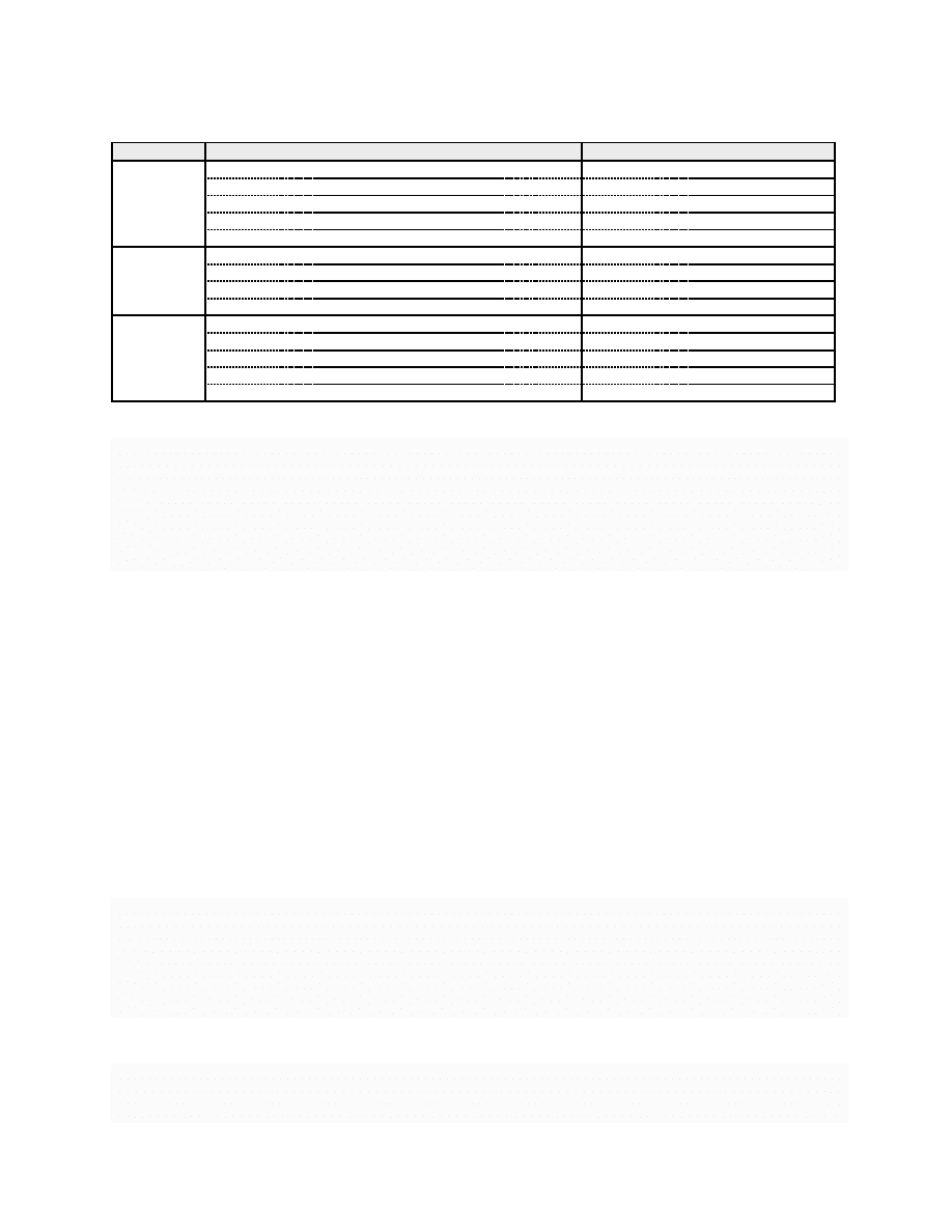
Table 3: Summary of the defined instruction classes
Class
Type of instructions
Example
Idempotent
ALU operations
add r1,r2,r3
- subs r1,r2,#8
instructions
Load instructions
ldrh r1,[r2,r3]
- ldrb r1,[r2,#8]
Store instructions
strh r1,[r2,r3]
- strb r1,[r2,#8]
Branch instructions
b <label>
- bx lr
Comparison instructions
cmp r1,#9
- cne r3,r4
Separable
Instructions with a register both source and destination
add r1,r1,#1
- str r0,[r0,#0]
instructions
Instructions with pre-indexed or post-indexed addressing
str r1,[r2,#8]!
- str r1,[r2],#8
Stack manipulation instructions
push
{r1,r2} - pop {r1,r2}
Instructions that use a rrx shift and write the flags
adds r1,r2,r3,rrx
Specific
Subroutine call instruction
bl <function>
instructions
If-Then (it) blocks
itte NE
Instructions for synchronization with external systems
sev
- yield - svc
Instructions for coprocessors
mcr p0,#0,r8,r2,r3
Instructions that both read and write the flags
adcs r1,r2,r3
- rrxs r1,r2
4
add
r1
,
r2
, #
10
5
eor
r3
,
r5
,
r 1
6
eor
r3
,
r5
,
r 1
7
b
c o n t i n u a t i o n
8
b
c o n t i n u a t i o n
9
e l s e
10
mov
r3
, #
10
11
mov
r3
, #
10
12
c o n t i n u a t i o n
Other replacement sequence for it blocks
We have also designed a specific replacement sequence for
it
blocks but this replacement has some limitations and can quickly become more costly than its equivalent
form with an if-then-else structure. Listing
gives an example of such an it block. If the condition NE holds,
(i.e.
if the Z flag is set), then the two following instructions (addne and eorne) are executed. Otherwise,
the last two instructions (subeq and moveq) are executed. The whole it block needs to be considered in
order to secure it. The solution we propose is to first apply our countermeasure scheme to every instruction
of the it block. Every instruction of a replacement sequence first keeps the same condition as the initial
instruction. The first it instruction is then duplicated. The second it instructions specifies one instruction
less than the first one. Moreover, both it instructions are to be updated depending on the instructions
that result of the replacement sequence of the instuctions of the initial it block. This step is presented in
Listing
. The second step consists in adding some it instructions, since it blocks cannot contain more
than 4 instructions, as illustrated in Listing
. Finally, the conditions set in the it instructions need to
be updated to match with the instructions of the it block they define. Listing
shows the secure code
corresponding to the it block code example given in Listing
Listing 10: First step for replacement of the it block given in Listing
1
i t ? ? ? NE
2
i t ??
NE
3
addne
r1
,
r2
, #
10
4
addne
r1
,
r2
, #
10
5
eorne
r3
,
r5
,
r 1
6
eorne
r3
,
r5
,
r 1
7
moveq
r3
, #
10
8
moveq
r3
, #
10
Listing 11: Second step for replacement of the it block given in Listing
1
i t ? ? ? NE
2
i t ??
NE
3
addne
r1
,
r2
, #
10
4
addne
r1
,
r2
, #
10
8

5
eorne
r3
,
r5
,
r 1
6
i t ? ? ? NE
7
i t ??
NE
8
eorne
r3
,
r5
,
r 1
9
moveq
r3
, #
10
10
moveq
r3
, #
10
Listing 12: Final replacement sequence of the it block given in Listing
1
i t t t t
NE
2
i t t t
NE
3
addne
r1
,
r2
, #
10
4
addne
r1
,
r2
, #
10
5
eorne
r3
,
r5
,
r 1
6
i t t e e
NE
7
i t e e
NE
8
eorne
r3
,
r5
,
r 1
9
moveq
r3
, #
10
10
moveq
r3
, #
10
Note that an it instruction should not appear in an it block. Thus, in case of a fault targeting one of the
duplicated it instructions, the code behaves as if there was only one it instruction. Otherwise, the second
it
instruction is executed in the it block defined by the first it instruction. The second it instruction has
actually no effect and is considered as a nop. However, some compilers may not accept such a construction.
In this case, we have to use traditional conditional sequences for if-then or if-then-else constructions and
apply our countermeasure scheme to each individual instruction of the resulting code as presented in Section
. Moreover, transforming first the it block into a classical if-then-else structure and then applying
the countermeasure scheme may induce a smaller overhead cost. Such a construction has been previously
presented in Listings
and
Other specific instructions
For some very specific instructions, defining a replacement sequence cannot
really be done. Those specific instructions include the group of instructions for coprocessors (mcr, lcr, ...)
or the instructions for synchronization with external systems (sev, yield, ...).
3.4
Summary of the defined instruction classes
To sum up, an overview of the defined instruction classes is shown on Table
. This table shows the different
types of instructions that are included in every class and provides a few examples for each type of instructions.
4
Formal verification of correctness and fault tolerance
In this section, we present how we formally prove the fault tolerance specification for the countermeasure
replacement sequences presented in Section
. Details about the models used for the verification approach
are presented in Section
and verification examples for some replacement sequences are presented in
Section
4.1
State machine model and specification to prove
A program acts as the application of transformations of the values stored in the set of registers or in memory.
Each instruction of the program acts like a function whose input is a configuration of registers and memory
and produces a new configuration. The program can then be represented as a transition system whose states
are configurations of registers and memory, and any transition mimics the state transformation induced by
an individual instruction execution.
4.1.1
Individual instruction model
Instead of proving the fault tolerance for a complete program, our model checking approach consists in
proving the fault tolerance for each replacement sequence proposed in our countermeasure scheme. Indeed,
9

# input r2, r3, flags
# output r1, flags
pc_init
: add r1, r2, r3
pc_final : next_instruction
pc init, pc f inal
∈ L
(R, F ) is the current state
(R
′
, F
′
) is the next state
t
: (R, F ) → (R
′
, F
′
) with
R.pc
= pc init
R
′
.r
1 = R.r1 + R.r2
R
′
.pc
= pc f inal
Figure 1: Transition system for the add r1, r2, r3 instruction
it is sufficient to certify that the output state (registers and memory configuration) after the replacement
sequence execution (with or without a fault injection) is equivalent to the normal output state after the initial
instruction execution. As this output state is also the input state for the following instruction, using such
a verification approach certifies that the next instruction will start from the right configuration. Moreover,
this enables to use model checking while avoiding state-explosion problem.
4.1.2
State machine model
As explained before, we can model the execution of a sequence of instructions by a transition system T S.
We define this transition system as T S = {S, T, S
0
, S
f
, L
}. S is the set of states, T the set of transitions
T
: S → S, S
0
and S
f
are the subsets of S which respectively gather the initial states and final states. The
final states from S
f
are absorbing states. A state from S is defined by the value of the different registers
(from the set of registers R which includes the program counter) and processor flags (from the set of flags
F
). Each transition from T is defined by the effect of an instruction on the registers and processor flags.
L
is a set of labels which correspond to the values the program counter can take. An example of such a
transition system for the add r1, r2, r3 instruction is shown in Fig.
. To prove that a countermeasure
for an instruction i is robust against a fault, we build two transition systems: one for the initial instruction
m
(i) and another one for its strengthened replacement sequence m
cm
(i).
Fault model
In any transition system m
cm
(i), one instruction skip fault may occur. An instruction skip
fault is modeled by a transition from a state to any following one. Such a faulty transition only modifies the
program counter. We add to the whole transition system a skip instruction faulty transition between every
pair of adjacent states. As we assume that only one skip instruction fault injection may occur, every fault
transition is guarded with a boolean which identifies that a fault has already occurred.
Flags and registers models
The set of registers is composed of some general-purpose registers (r0-r12),
a stack pointer (r13), a link register (r14) and a program counter (r15). The 5 processor flags are: C (carry),
N (negative), Z (zero), V (overflow), Q (saturation). These flags can be set by some instructions and are
used by several others. The conditional jumps are among the instructions that use those flags. Each flag is
modeled as a 1-bit register. All the other registers are modeled as 4-bit registers. This width is sufficient to
model the arithmetic and logic operations as well as the flags computations and enables to keep a reasonable
complexity for the model checker. Moreover, modeling all the registers is not necessary since an instruction
only reads a subset of the registers and writes on the destination registers. Besides, according to our fault
model, the registers that are not modified by an instruction cannot be modified by a fault. Thus, for a given
m
(i) or m
cm
(i), the set of registers R is only composed of the subset of registers that are manipulated by i or
its replacement sequence cm(i). Extra registers used in cm(i) are supposed to be dead after the occurrence
of the instruction i in the initial program.
Memory model
Since in our fault model we assume the memory cannot be corrupted, modeling the
memory is not relevant. To ensure that a write to the memory took place, we only need to ensure that
the corresponding instruction has been executed at least once. As explained later in this section, we add
a counter variable to m(i) and m
cm
(i) in order to achieve this. For the loads from the memory, we use
symbolic values as the values cannot be corrupted and they also do not matter since the formal verification
we use consists in checking the equivalence for any value. The important point is to give the same symbolic
10
R1 = R1 + R3
PC = PC1
PC = PC0, R1 = V1, R3 = V3, FLAGS = FLAGS_VALUE
ADD
CM(ADD)
PC0
add R2, R1, R3
R2 = R1 + R3
PC = PC0_1
PC = PC0_2
fault
add R2, R1, R3
R2 = R1 + R3
PC = PC0_2
R1 = R2
PC = PC0_3
mov R1, R2
PC = PC1
R1 = R2
PC = PC1
fault
PC = PC0_3
fault
add r2, r1, r3
add r2, r1, r3
mov r1, r2
mov r1, r2
PC = PC0_1
fault
PC0_1
PC0_2
PC0_3
PC1
PC1
PC0
add R1, R1, R3
mov R1, R2
add r1, r1, r3
P1: AF(ADD.PC = PC1)
P2: AF(CM(ADD).PC = PC1)
P3: AG(((ADD.PC=PC1)*(CM(ADD).PC=PC1)) =>
ADD.R1 = CM(ADD).R1 &
ADD.FLAGS = CM(ADD).FLAGS)
Figure 2: Model for a non-idempotent instance of the add instruction and its countermeasure
11
fault
PC0
PC1
PC = PC1
cpt++
str R3, [R1, R2]
STR
PC = PC0, R1 = V1, R2 = V2, FLAGS = FLAGS_VALUE, cpt = 0
CM(STR)
str R3, [R1, R2]
cpt++
PC = PC0_bis
PC0
str R3, [R1, R2]
cpt++
PC = PC1
str r3, [r1, r2]
str r3, [r2, r1]
str r3, [r1, r2]
PC1
PC0_bis
PC = PC0_bis
fault
PC = PC1
P1 : AF(STR.PC=PC1)
P2 : AF(CM(STR).PC=PC1)
P3 : AG((STR.PC=PC1 * CM(STR).PC=PC1) =>
(CM(STR).cpt = 2 + CM(STR).cpt = 1))
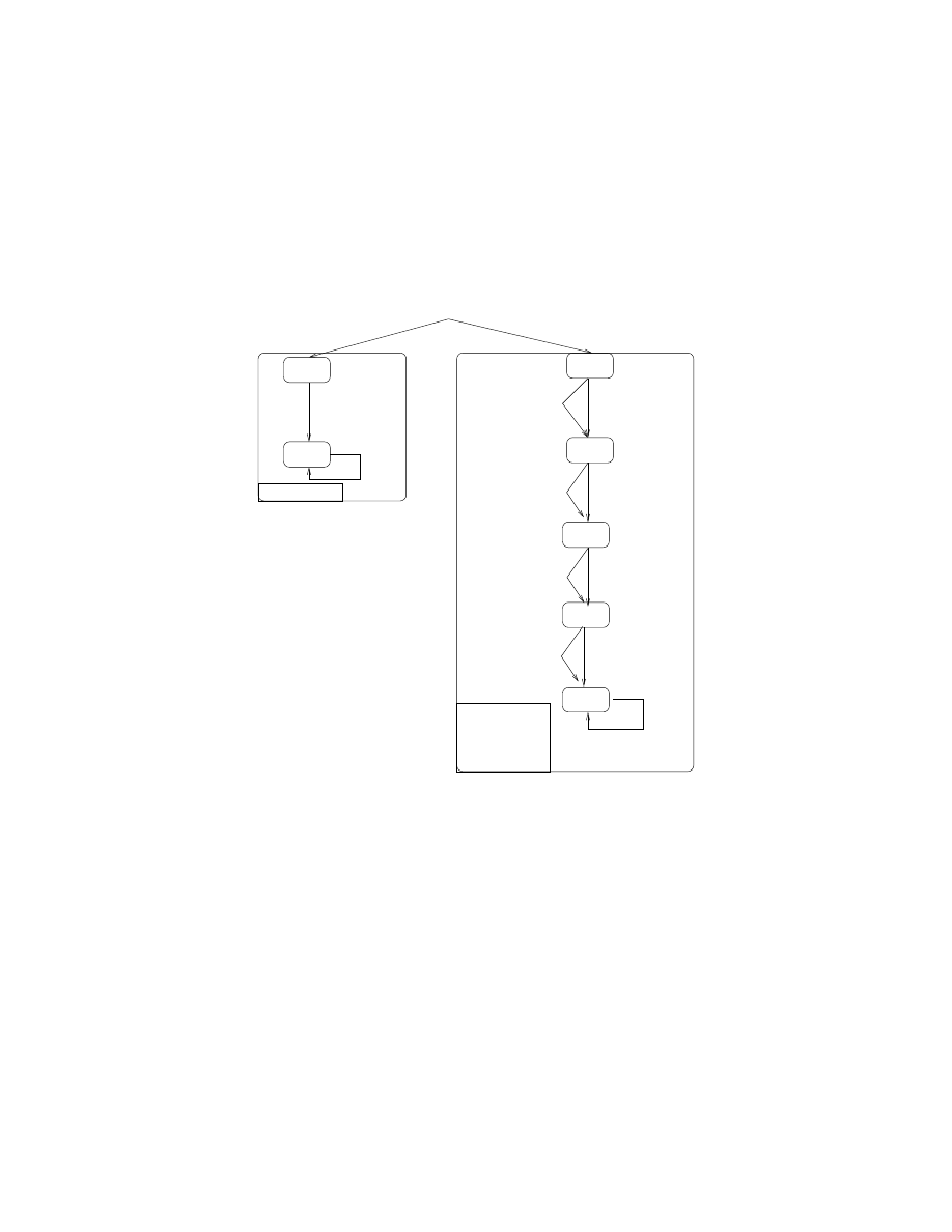
Figure 3: Model for an idempotent instance of the str instruction and its countermeasure
value to any loads at a given address for the transition system m(i) (when i is a load instruction) and for
m
cm
(i). This is achieved by adding an input variable for each memory address that is read by i and cm(i)
to both transition systems. These variables contain the needed symbolic values.
Vis model checker
We have chosen to use the Vis model checker
to prove the fault tolerance of our
countermeasure scheme. This tool can take as input a transition system described with a subset of the Verilog
hardware description language. Using Verilog is convenient to model transition systems which manipulate
registers and bit vectors. The Vis model checker supports symbolic model checking techniques which enable
to perform the proof in a symbolic way without having to enumerate each value for the registers. In [
Fox et al. proposed a model of the ARMv7 architecture based on the HOL4 interactive theorem prover.
However, this tool makes some proofs that are much more complex than the ones we need for the equivalence
checking of finite models (the formal approach we propose to use in this paper) and the verification of rather
simple properties on those models.
4.1.3
Specification to prove
To prove the equivalence of the output of an instruction and its replacement sequence, we prove the validity
of logic formulas on the two models. To perform such a verification, we use a specific construction in which
the two transition systems m(i) and m
cm
(i) have the same values for the set of registers R (except for the
program counter), the set of flags F and the symbolic values (for the memory loads) in their initial states.
Such constructions are presented in Fig.
and
. We then need to prove that m(i) and m
cm
(i) always
reach a final absorbing state. Moreover, we also need to prove that, when m(i) and m
cm
(i) reach a final
state, the values for the set of alive registers R
′
(except for the program counter) and flags F
′
are similar.
Such properties to check are expressed with the CTL temporal logic.
5
http://vlsi.colorado.edu/˜vis/
12
BL
addr ry, <return_label>
addr ry, <return_label
b @fct
b @fct
add lr, ry, 1
add lr, ry, 1
PC0
PC1
@fct
PC0
PC0_1
PC0_2
PC = PC0 , cpt = 0
cpt++
addr ry, <return_label>
fault
PC = PC0_2
PC = PC0_1
fault
Ry = PC1
PC = PC0_1
Ry = PC1
PC = PC0_2
PC = @fct
LR = PC1
PC = LR
fault
fault
PC = PC0_4
PC = @fct
@fct
cpt++
b @fct
b @fct
PC1
return_label :
PC = PC1
fault
PC = PC0_5
fault
PC = @fct
( PC = <return_label>)
PC0_3
PC0_4
PC0_5
PC = PC0_3
PC = PC0_3
PC = PC0_4
add lr, ry, 1
addr lr, ry, 1
addr ry, <return_label>
LR = Ry + 1
LR = Ry + 1
CM(BL)
Properties to be checked
P3 :
P2 : AF(BL.PC = PC1)
P1 : AF(BL.PC = PC1)
AG( ((BL.PC = PC1) *(CM(BL).PC = PC1))
=> ((BL.cpt = 1) * CM(BL).cpt = BL.cpt)))
bl @fct
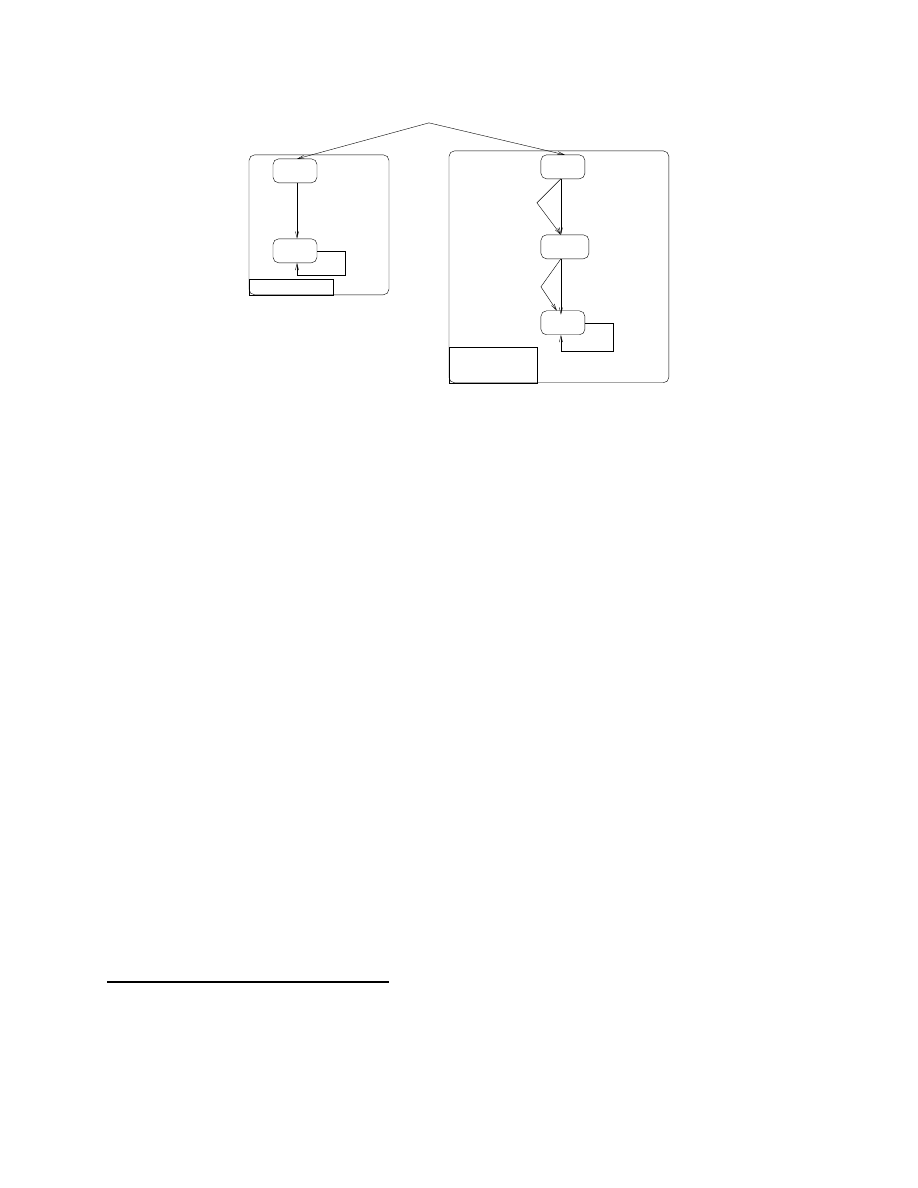
Figure 4: Transition systems for the bl instruction and its replacement sequence
MC: formula passed - AG(AF(adcs.pc=PC1))
MC: formula passed - AG(AF(cm(adcs).pc=PC1))
MC: formula passed - AG(((adcs.pc=PC1*cm(adcs).pc=PC1)->LIGHT_RESULT=1))
MC: formula failed - AG(((adcs.pc=PC1*cm(adcs).pc=PC1)->RESULT=1))
Figure 5: VIS Model Checker output for the equivalence checking of the adcs instruction
13
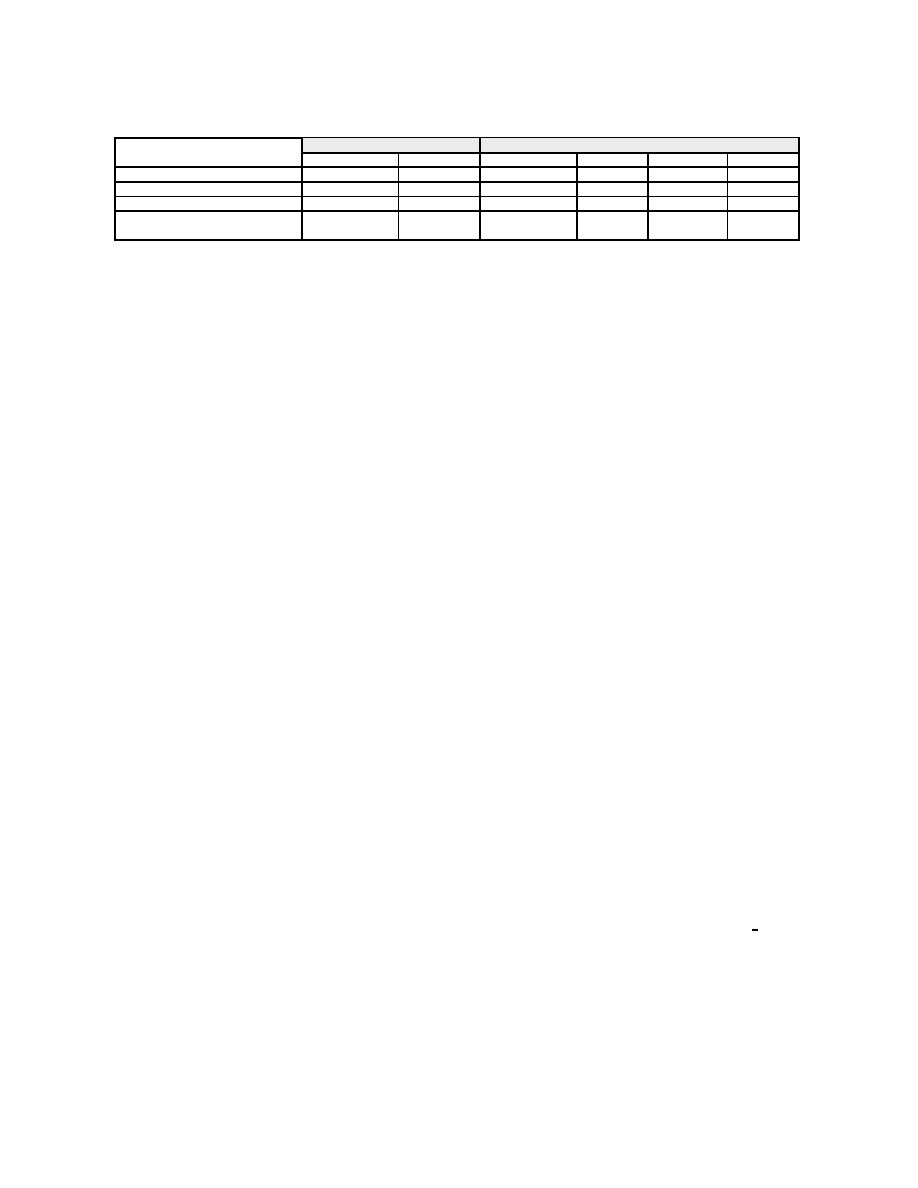
Table 4: Countermeasures overhead for several implementations
Implementation
Without countermeasure
With countermeasure
Clock cycles
Code size
Clock cycles
Increase
Code size
Increase
AES
9595
490 bytes
20503
113.7 %
1480 bytes
202 %
MiBench AES
9294
3372 bytes
26618
186.4 %
9776 bytes
189.9 %
MiBench SHA0
4738
746 bytes
10558
122.8 %
2076 bytes
178.2 %
AES with countermeasure
9595
490 bytes
11374
18.6 %
1874 bytes
282.5 %
on the last two rounds
4.2
Formal verification for some replacement sequences
4.2.1
Idempotent and separable instructions
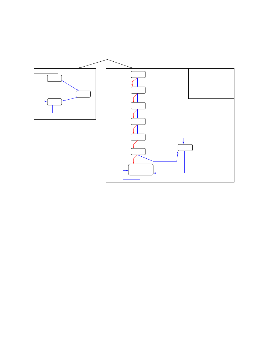
The left part of Fig.
shows the state machine corresponding to the transition system for a non-idempotent
add r1,r3
instruction. The program counter is updated and depending on the instruction, the registers
or the flags may be updated too. The replacement sequence uses a dead register r2 and two extra mov
instructions to write the result to the destination register r1. Its transition system is modeled by the state
machine on the right part of Fig.
. To prove that the replacement sequence is fault tolerant against a
possible instruction skip, both state machines are fed with the same values for the source registers (r1 and
r3
) and flags. Then, the validity of three CTL logic formulas has been checked with the Vis model checker.
P1 and P2 express the fact that in both state machines any path from an initial state goes to a final state.
P3 expresses the fact that in this final state, for all possible values in the source registers, the values in r1
and the flags are identical in m(i) and m
cm
(i). Fig.
presents the transition systems for an idempotent
memory write, namely an str r3, [r1, r2] instruction, and its replacement sequence. In this case, as the
instruction writes the content of r3 to the memory at the address r1+r2, and as we consider an instruction
skip fault model, no proof is needed on the value hold by the registers. We only need to make sure that at
least one str instruction has been executed. A counter variable is added to the definition of a state. This
counter is set to 0 and is incremented by any transition which corresponds to a str instruction. P1 and P2
express the fact that any path goes to the last state. P3 expresses the fact that the number of writes made
by the replacement sequence greater or equal to the number of writes made by the initial instruction (which
is equal to 1).
4.2.2
Specific instructions
Subroutine call: the bl instruction
Figure
shows the state machines for the bl instruction and its
replacement sequence. In both corresponding transition systems, we have added a label @f ct to model the
target of the subroutine call. Transitions from a state in which P C = @f ct assign the link register to the
PC. Such a transition models the return of the function and also increments a counter. Then, properties P1
and P2 to be checked by the model checker express that any path from an initial state goes to a final state.
Property P3 expresses the fact that in a final state the number of calls to the function (the counter values)
are the same. Validity of property P3 ensures that the function has been executed only once while validity
of P1 and P2 ensures that the control flow comes back to the calling function.
Instructions that read and write the flags
For the adcs instruction and its replacement sequence, as
presented in Listing
, the CTL properties are the same as the ones that were used for the add instruction.
However, the property that deals with the equality of the destination register and the flags is not valid if a
fault targets the last adcs instruction. Relaxing the constraint on flags equality (expressed as LIGHT RESULT)
makes this property valid as shown with the output of the Vis model checker in Fig.
. To sum up, this
countermeasure can only be used if the flags are not used before being set again after the adcs instruction.
4.2.3
Verification statistics
The verification process is based on modeling the arithmetic and logic operation performed by instructions
and modeling their effects on the flags. Thus, the minimal size required to model the registers is the minimal
one that enables to precisely model the effects on the flags. As a consequence, modeling registers with a 4-bit
14

size is relevant. However, the verification process leads to the same results (passed or failed) for registers
modeled with a 4-bit length or for larger sizes. Moreover, the verification process duration and the size of
the transition system are related to the size of the registers. The verification process required less than 1
second per instruction with a 4-bit register size for all the instructions, and less than 1 minute for almost
all the instructions with a 16-bit register size. As an example, it needed 29 hours to complete for the most
expensive umlal instruction with a 16-bit register size. Moreover, the model checker we used could not
build the internal representation or carry out the verification for registers larger than 24 bits for all the
instructions.
5
Application to several implementations
In this section, we applied our countermeasure scheme to several codes. Two of them are implementations of
the AES-128 symmetric encryption algorithm, and the last one is an implementation of the SHA-0 algorithm.
We developed the first AES implementation, in which every round key is calculated before the associated
AddRoundKey
operation. The second AES implementation and the SHA-0 implementation come from the
MiBench embedded benchmark suite [
]. We provide an estimation of the overhead cost brought by our
countermeasure scheme for those three implementations and perform an exhaustive instruction skip simula-
tion on an ARM Cortex-M3 microcontroller to confirm the effectiveness of our approach. The chosen target
is an up-to-date 32-bit microcontroller based on the ARM Cortex-M3 processor [
]. This microcontroller
uses an ARMv7-M Harvard architecture and runs the Thumb-2 instruction set [
Estimation of the overhead cost
The overhead cost in terms of clock cycles and code size for the three implementations that use our coun-
termeasure scheme is shown on the first three lines of Table
. For those implementations, the whole code
has been strengthened with our methodology and both overhead costs are high.
Another approach consists in applying our countermeasure to a specific chosen part of the algorithm.
As an example, in terms of cryptanalysis, fault injections are supposed to be harder to exploit if the fault
does not target the last two rounds. Thus, as shown on the fourth line of Table
, it could be possible
to reduce the overhead in terms of clock cycles by applying our countermeasure scheme to the last two
rounds only. This last scenario is just a possible example of optimization and some cryptanalysis attacks
may still exist. Nevertheless, it aims at showing that the overhead costs can be significantly reduced with a
good knowledge about the algorithm to strengthen and about some possible vulnerabilities in its assembly
code. It is important to mention that all the instructions from the tested codes could be replaced by using
our countermeasure scheme. Moreover enough dead registers were always available for all the replacement
sequences that required some extra registers.
To sum up, the overhead cost brought by our countermeasure scheme is high, but remains comparable to
the one brought by classical algorithm triplication or other software approaches for fault tolerance. However,
unlike such classical algorithm duplication or triplication approaches, our countermeasure scheme should be
resistant to double fault attacks in a time interval longer than a few clock cycles.
6
Conclusion
In this paper, we have presented a countermeasure scheme that enables to strengthen an embedded program
and make it tolerant to instruction skip faults. In our countermeasure scheme, we have built a fault-tolerant
replacement sequence for almost all the instructions of the whole Thumb-2 instruction set. The instructions
can be divided into three classes, which all have their dedicated replacement sequences. We have also
provided a formal verification process in order to guarantee the correctness and the fault tolerance of our
replacement sequences for each class of instructions.
Finally, we do not claim our scheme enables a full protection against fault attacks. Nevertheless, such an
approach enables to add a reasonably good security level to an embedded program, without requiring any
extra hardware countermeasure and any specific knowledge about the embedded program. The overhead cost
15

brought by using such a countermeasure is comparable to the extra cost brought by using classical algorithm-
level temporal redundancy approaches and can be reduced with a more accurate knowledge about the
sensitive parts that should be protected. Moreover, using a very fine-grained redundancy at the instruction
scale makes the multiple fault attacks less practical with a reasonable cost equipment.
References
[1] ARM. ARM Architecture Reference Manual - Thumb-2 Supplement, 2005.
[2] Josep Balasch, Benedikt Gierlichs, and Ingrid Verbauwhede. An In-depth and Black-box Character-
ization of the Effects of Clock Glitches on 8-bit MCUs. In 2011 Workshop on Fault Diagnosis and
Tolerance in Cryptography. IEEE, September 2011.
[3] H. Bar-El, H. Choukri, D. Naccache, M. Tunstall, and C. Whelan. The Sorcerer’s Apprentice Guide to
Fault Attacks. Proceedings of the IEEE, 94, February 2006.
[4] Alessandro Barenghi, Guido M. Bertoni, Luca Breveglieri, Mauro Pelliccioli, and Gerardo Pelosi. In-
jection Technologies for Fault Attacks on Microprocessors. In Marc Joye and Michael Tunstall, editors,
Fault Analysis in Cryptography, Information Security and Cryptography, pages 275–293. Springer Berlin
Heidelberg, 2012.
[5] Alessandro Barenghi, Luca Breveglieri, Israel Koren, and David Naccache. Fault Injection Attacks on
Cryptographic Devices: Theory, Practice, and Countermeasures. Proceedings of the IEEE, 100(11):3056–
3076, November 2012.
[6] Alessandro Barenghi, Luca Breveglieri, Israel Koren, Gerardo Pelosi, and Francesco Regazzoni. Coun-
termeasures against fault attacks on software implemented AES. In Proceedings of the 5th Workshop
on Embedded Systems Security - WESS ’10, New York, New York, USA, 2010. ACM Press.
[7] Dan Boneh, RichardA. DeMillo, and RichardJ. Lipton. On the importance of checking cryptographic
protocols for faults. In Advances in Cryptology - EUROCRYPT ’97, volume 1233 of Lecture Notes in
Computer Science, pages 37–51. Springer Berlin Heidelberg, 1997.
[8] Boutheina Chetali and Quang-Huy Nguyen. Industrial use of formal methods for a high-level security
evaluation. In FM 2008: Formal Methods, volume 5014 of Lecture Notes in Computer Science, pages
198–213. Springer Berlin Heidelberg, 2008.
[9] Maria Christofi, Boutheina Chetali, Louis Goubin, and David Vigilant. Formal verification of a CRT-
RSA implementation against fault attacks. Journal of Cryptographic Engineering, February 2013.
[10] Amine Dehbaoui, Jean-Max Dutertre, Bruno Robisson, and Assia Tria. Electromagnetic Transient
Faults Injection on a Hardware and a Software Implementations of AES. In 2012 Workshop on Fault
Diagnosis and Tolerance in Cryptography. IEEE, September 2012.
[11] Anthony Fox and Magnus O. Myreen. A trustworthy monadic formalization of the armv7 instruction
set architecture. In Interactive Theorem Proving, volume 6172 of Lecture Notes in Computer Science,
pages 243–258. Springer Berlin Heidelberg, 2010.
[12] M.R. Guthaus, J.S. Ringenberg, D. Ernst, T.M. Austin, T. Mudge, and R.B. Brown. MiBench: A free,
commercially representative embedded benchmark suite. In Proceedings of the Fourth Annual IEEE
International Workshop on Workload Characterization. WWC-4. IEEE, 2001.
[13] Duˇsko Karaklaji´c, J¨orn-Marc Schmidt, and Ingrid Verbauwhede. Hardware Designer’s Guide to Fault
Attacks. IEEE Transactions on Very Large Scale Integration (VLSI) Systems, 2013.
[14] Marcel Medwed and J¨orn-Marc Schmidt. A Generic Fault Countermeasure Providing Data and Program
Flow Integrity. In 2008 Workshop on Fault Diagnosis and Tolerance in Cryptography. IEEE, August
2008.
16

[15] Nicolas Moro, Amine Dehbaoui, Karine Heydemann, Bruno Robisson, and Emmanuelle Encrenaz. Elec-
tromagnetic Fault Injection: Towards a Fault Model on a 32-bit Microcontroller. In 2013 Workshop on
Fault Diagnosis and Tolerance in Cryptography. IEEE, August 2013.
[16] Minh Huu Nguyen, Bruno Robisson, Michel Agoyan, and Nathalie Drach. Low-cost recovery for the
code integrity protection in secure embedded processors. In 2011 IEEE International Symposium on
Hardware-Oriented Security and Trust. IEEE, June 2011.
[17] Pablo Rauzy and Sylvain Guilley. A formal proof of countermeasures against fault injection attacks on
CRT-RSA. Journal of Cryptographic Engineering, December 2013.
[18] J¨orn-Marc Schmidt and Christoph Herbst. A Practical Fault Attack on Square and Multiply. In 2008
Workshop on Fault Diagnosis and Tolerance in Cryptography. IEEE, August 2008.
[19] Sergei Skorobogatov. Local heating attacks on Flash memory devices. In 2009 IEEE International
Workshop on Hardware-Oriented Security and Trust, pages 1–6. IEEE, 2009.
[20] Elena Trichina and Roman Korkikyan. Multi Fault Laser Attacks on Protected CRT-RSA. In 2010
Workshop on Fault Diagnosis and Tolerance in Cryptography. IEEE, August 2010.
[21] Joseph Yiu. The Definitive Guide To The ARM Cortex-M3. Elsevier Science, 2009.
[22] Loic Zussa, Jean-Max Dutertre, Jessy Cl´edi`ere, Bruno Robisson, and Assia Tria. Investigation of timing
constraints violation as a fault injection means. In DCIS, Avignon, France, 2012.
17
Document Outline
- 1 Introduction
- 2 Related works and fault model
- 3 Countermeasure scheme
- 4 Formal verification of correctness and fault tolerance
- 5 Application to several implementations
- 6 Conclusion
Wyszukiwarka
Podobne podstrony:
Using Two Part Counterpoint For Non Twelve Tone Music
Din 16903 Threaded Inserts For Plastic Injection Molding
FIDE Trainers Surveys 2018 07 31 Vladimir Grabinsky Garry Kasparov s patent for prophylactic move in
Mastering Ninject for Dependency Injection [eBook]
Lattice Cryptography for the Internet
Injectable liquid copolymers for soft ti
A Potency Relation for Worms and Next Generation Attack Tools
Hydrogen Gas Injector System For Internal Combustion Engine
3726A Fault Finding Petrol Injection
NASA CR 180678 Calculation of Aerodynamic Characteristics at High Angles of Attack for Airplane Conf
SMeyer CA1233379A1 Hydrogen Gas Injection for Internal Combustion Engine
Injection Molding Basics for the Minimal Mold(1)
Initial Assessments of Safeguarding and Counterintelligence Postures for Classified National Securit
więcej podobnych podstron