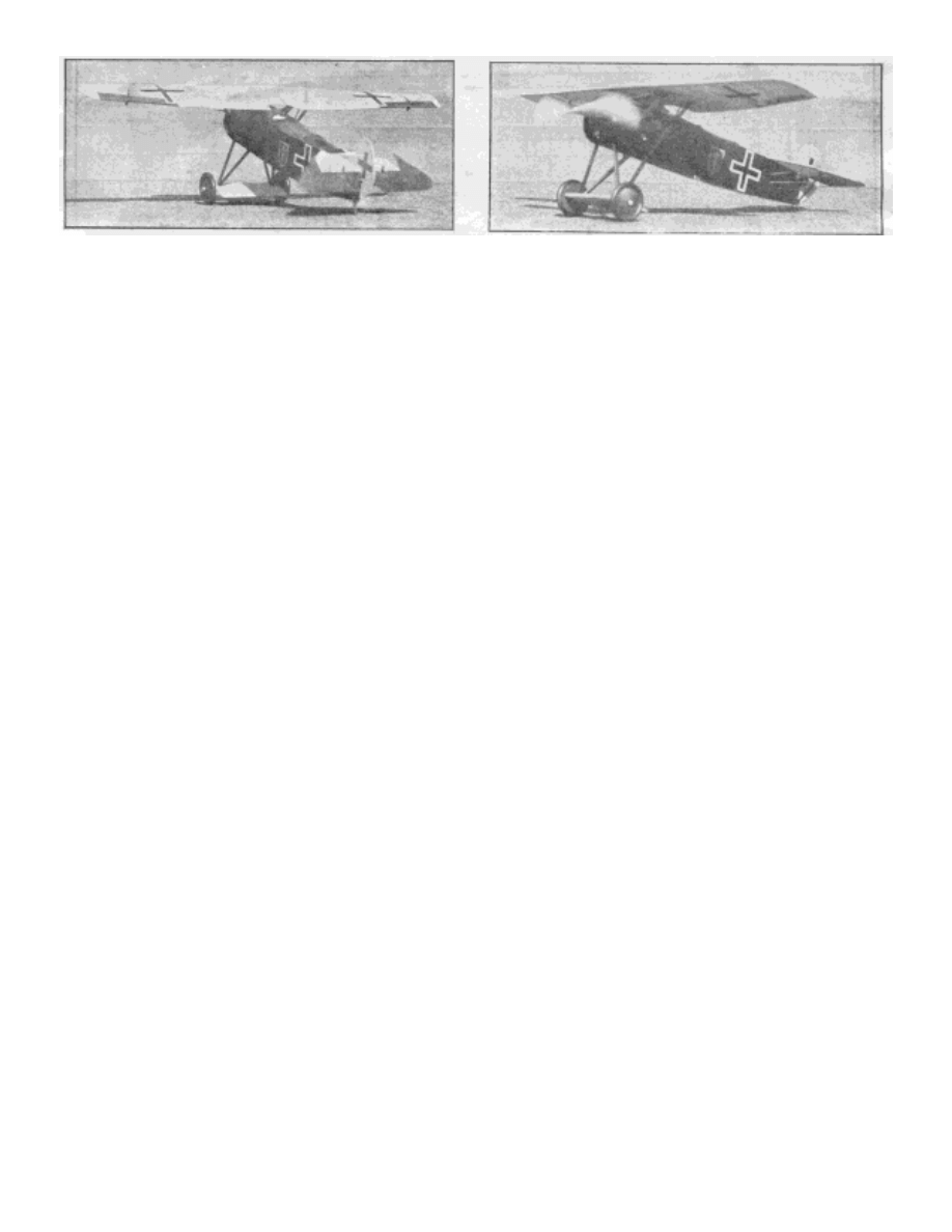
Details are carefully carried out. Note movable controls The high wing gives it unusual stability
Build and Fly the Fokker D- 8
Complete Data From Which You Can Build a Successful Model of a Famous
German World War Fighter
By HARRY SHAFFER
WHEN a flying scale model is to be built, it is wise to select a type of ship which lends itself to stability.
As a rule, the type which fulfills this requirement to the highest degree is a high-wing monoplane or parasol. In
such ships the center of gravity is low and the wing area smaller in proportion to the tail surfaces. Then again,
the monoplane type is usually superior in flying qualities to the biplane.
In looking through our list of planes and giving consideration at the same time to these factors in order
to make a wise selection, we could not help being impressed with the general design of the Fokker D-8.
Examining the design of this plane more carefully, we found that it had the necessary factors to the fullest
degree. It is a monoplane, the wing is parasol, the center of gravity is low and the tail surfaces are quite large in
proportion to the wing area. Only one drawback is apparent; the wing is located quite near the nose. This fact
might make it difficult to balance the model actively for flight. However this fault may easily be corrected by
addling a little weight to the forward end of the ship. This selection was well justified after I had made the first
flying model for it proved to be an excellent flyer.
Another factor which makes this ship interesting to build is the history that it made for itself during the
World War. It made its appearance in the fall of 1918, though very few of these fighters actually saw combat.
The planes that actually reached the front were outstanding in their ability to cope with Allied machines. It was
powered with a 110 h.p. Oberursel rotary motor which grave the ship a speed of approximately 115 m.p.h. Like
many German ships, this plane was ahead of its time as regards its general design. The wings were cantilever
without any brace wires.
Since the World War the trend of development has progressed continuously toward this type of plane.
The Douglas Transport, Boeing model 247 and other similar ships are good examples.
Before trying to construct the model, it is wise to look over the plans carefully and familiarize yourself
with the details of construction. Do not start until you have a clear picture in your mind of the entire ship. A
great deal of material has been wasted by such procedure. After you feel that you understand the plans
thoroughly, gather all the necessary material together and commence your work.

Fuselage
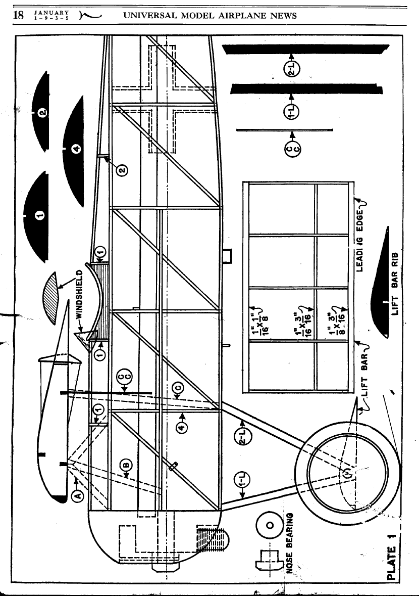
Plates No. 1 and 2, giving the side view, are used to construct the sides. of this model. By placing the
drawing over a board and using pins, the longerons are thus held in place. Both sides of the fuselage are made at
one time, thus assuring them of being the same.
The vertical braces are now cut and placed in by gluing the bottom one first and then putting the top
ones in and gluing them. When the two sides are completely dry, separate and begin to glue the cross braces
starting at the front of the model. This makes the frame of the fuselage.
We must next cut the bulkheads which are found on plate 1. These are made from 1/16” flat balsa and
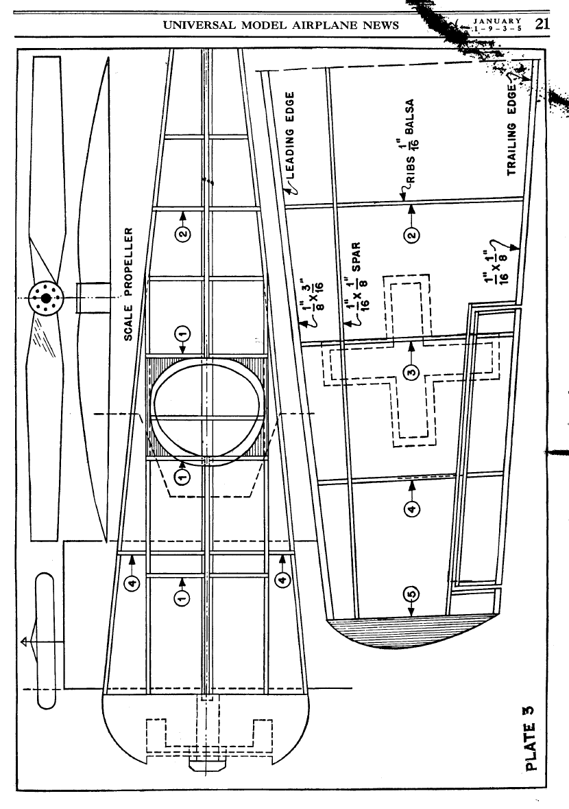
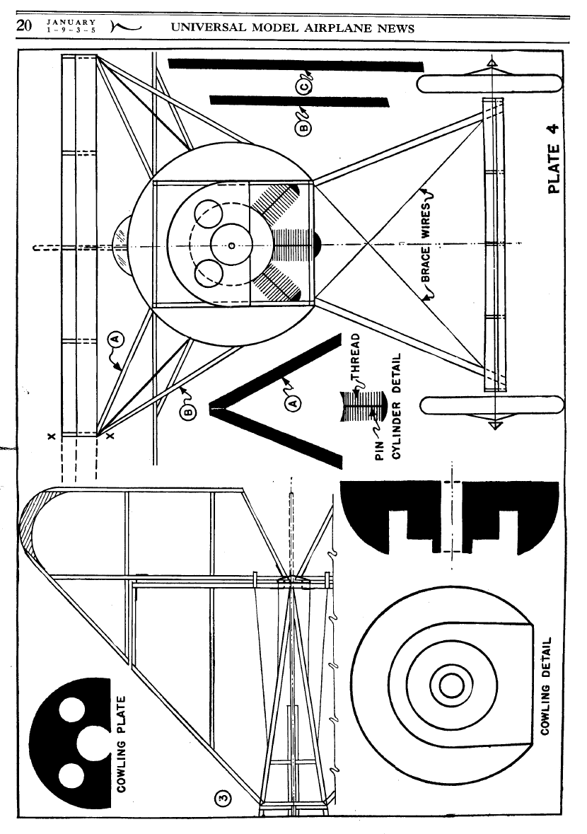
glued in their proper places. The cowling must now be made. This will have to he carved or made on a lathe, the
latter being the best way. The drawing on plate 3 shows the exact shape.
Take the best of cart in making the cowling, the point where the nose button joins the cowling is rather thin,
thus requiring much care in turning. After it is completely shaped, sand smooth with very fine sandpaper and
give about three coats of banana oil. This when doped will dry with a bright luster.
The inside of the cowling is painted black and then the cylinders are made, painted and glued in place.
This complete the cowling. Now that the cowling is made, glue to front of fuselage and the stringers are now
glued in place. The motor stick is glued in place; (Note the 1/l6" x 1/8" support); the rear hook being placed on
the motor stick before being glued in the fuselage. The cockpit is built up from 1/16" flat balsa. Give the
fuselage a light sanding so as to secure a smooth covering job.
Cover all of the straight surfaces first, using banana oil as adhesive, talking a small strip at a time. The
curved parts of the fuselage are covered now taking them in small sections also. After the fuselage is covered,
spray lightly with water. An insect spray works very well, and let it dry. As soon as it is dry, give it two coats of
dope. Any of the leading model airplane supply houses handle a good grade of dopes. In the model pictured it is
colored red fuselage with cream wings and Black details. The dark fuselage and light wing color combination
seems to be as attractive as any two color combination.
After the two coats of dope are applied, start on the details of the fuselage. The steps and handles are made of
No. I 2 music wire and glued in place. The breather pipe, which is made from 1/16" square balsa, is colored
black and glued in place and the shell ejector chute, also made of 1/ 16" square balsa, is colored Black and
glued in place. The cockpit padding is cut from 1/16" flat balsa, colored black and glued in place. In gluing this,
be careful not to drop any glue on the paper covering or it will draw it, thus
forming wrinkles. The tail skid is
made from 1/8" flat balsa colored black and glued in place. Make the wind shield from thin celluloid and glue
in place, thus completing the fuselage
.
Landing Gear
The landing gear is made from 1/8" x 3/16" hard balsa, or bamboo strips (preferred). Make the struts as
shown and streamline. They are now painted black and glued in their proper places.
Lift Bar
The lift bar is made the same as if it were a wing. Five ribs are cut from 1/16" flat balsa and notched.
The main spar ( I /16" x 3/16") is pinned to the drawing and the ribs glued in their place to it. The trailing edge
(1/16" x 1/8") and the leading edge (1/8" x 3/16") are now glued in place. The axle is one solid piece of No. 12
music wire. Glue it to the side of the main spar. When it is dry, give a light sanding and cover. Spray it with
water and let it dry.
When dry, give two coats of cream dope and attach to the landing gear struts now on the fuselage. The
wheels are 1-7/8" in diameter, turned on a lathe like the cowling and are colored with black and red discs and
placed on axles. They are held on by small clots of glue. This completes the landing gear.
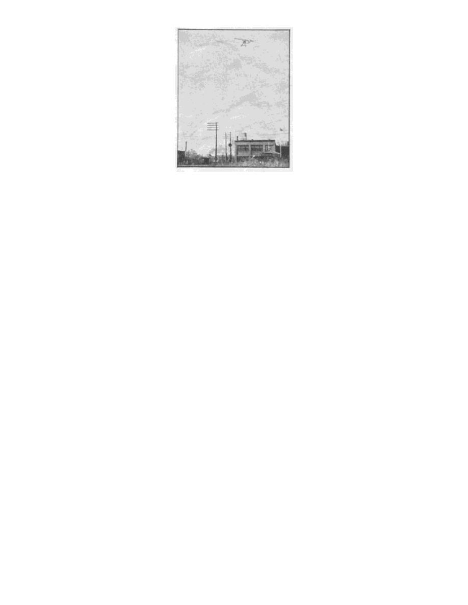
The finished model in full flight provides a real thrill
Tail Surfaces
The rudder is built completely of 1/16" square and 1/ 16" flat balsa. Cut the curved piece, or trailing
edge of the rudder from 1/16" flat balsa. Start by pinning the 1/16" square pieces to the drawing and gluing
them together. The copper wire hinges are now glued in place, making the rudder movable with the fin. Sand
the whole framework lightly, cover, water dope it and then give two coats of cream dope to the fin and two
coats of red dope to rudder.
The stabilizer is also built completely of 1/16" square and 1/16" flat balsa. The 1/16" flat curved parts
are now cut and pinned to the drawings. The 1/16" square is now cut to fit and glued in place. The copper wire
hinges are now glued in place, thus making the elevators movable with the stabilizer. Sand the completed
frameworks lightly, cover, water dope and give two coats of cream dope to the stabilizer and two coats of red
dope to the elevators, the tail surfaces being done and glued to the fuselage in their proper places. The elevator
and rudder horns, with the thread cables are now glued in place. The horns are colored black. This completes
the tail surfaces or rear part of the plane.
Wing Struts
The wing struts are made from 1/8” x 3/16" hard balsa sanded to a streamline section. The full size of
these struts will be found on plate 4. After they are cut to size and streamlined, they are painted black. When
they are dry, pin to the fuselage in their proper places and glue. They are now ready to receive the wing.
Wing
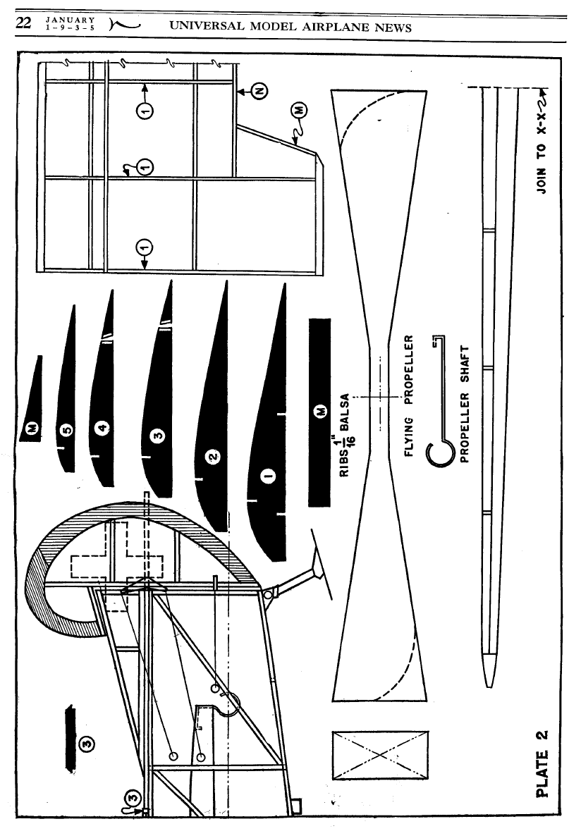
Make all ribs from 1/16" flat balsa. The size and number of each is shown on plate 5. One must always
remember that the flying properties of a plane lie almost completely in accurate airfoil section. Therefore, cut
them to the exact size shown on the drawings. The two sub-spars are pinned on the drawing and the ribs are
glued in their proper places on the sub-spars. The leading edge (3/16" x 1/8” ) is now pinned to the drawing and
glued to the center section ribs. The trailing edge (1/16" x 1/8") is done in the same manner. The main spar is
now glued to the section ribs. This makes the center section with the main spar, leading and trailing edges
extending from it. Crack the leading and trailing edges at the center section and pin to their places on the
drawing. The solid wing tips are now made and are glued to the leading and trailing edges in the proper place.
Now, put No. 2 to No. 4 ribs in their places and then crack the main spar at the center section and glue to
the notches in the ribs just added. Cut and fit main spar snug with wing tip and glue to it. The aileron spar is
glued to the aileron ribs which are cut to allow it to pass through. The small sub-ribs must now he glued in
place. The copper wire hinges are now added, making the ailerons movable with the wing. A slight dihedral is
best for best flying results, although it is not to scale. Give the wing a light sanding, cover, water dope and give
two coats of cream dope. The ailerons are given two coats of red dope. Add the aileron horns and control thread
wires. The horns are colored black. The wing is pinned down over waxed paper after doping. The wing is now

glued to the wing struts now on the fuselage. You can now put on the aileron control wire tubes number C-C on
drawings.
General Assembly
The propeller is carved from a hard balsa block 1-1/4" x 5/8" x 8" and is laid out as shown on plate 2.
After it is carved, sand smooth and balance. Give two coats of banana oil and two coats of cream dope. After it
is dry, assemble with three washers to the nose bearing, one washer glued to the propeller, the other to the nose
button and the other being free. This plane is powered with six strands of 1/8" flat rubber which is now put in
the fuselage and connected to the propeller. The iron crosses are made from black and white tissue paper and
glued in their places. They are shown by dotted line on the drawings.
Flying instructions
The best place to fly your model is in a large field with tall grass. Give about fifty turns and hand-launch
it. If it dives, raise the elevators a bit. If it climbs, lower the elevators. Do this until you get it perfectly
balanced. To make it circle, bend the rudder in the way you want it to go. If these plans have been followed
closely, you will have a beautiful model and a wonderful flyer. (If the model proves to be tail heavy, weight the
nose to create the proper balance).
Scanned from January 1935
Universal Model Airplane News
Wyszukiwarka
Podobne podstrony:
Peugeot 406 D8 instrukcja obslugi PL by mobopx
D8
d8
D8 g
D8 Doskonalenie sprawności językowej, metodyka
D8
Amazone D8 D8E AD AD8 tabele wysiewow PL
d8
D8 P
DTS D8 Delio v03 20060823
D8 rzeczowniki niepoliczalne pojemniki itp PL
D8 rzeczowniki niepoliczalne pojemniki itp ANG
Peugeot 406 D8 instrukcja obslugi PL by mobopx
ssp167 d8
D8 40 Super
D8 RIVOLUZIONE FRANCESE
Delage D8 SS
więcej podobnych podstron