U.S. Department
of Transportation
Federal Aviation
Administration
Advisory
Circular
1
Initiated by:
AFS-340
DATE:
5/24/95
AC NO:
90-89A
AMATEUR-BUILT AIRCRAFT AND ULTRALIGHT
FLIGHT TESTING HANDBOOK

U.S. Department
of Transportation
Federal Aviation
Administration
Advisory
Circular
i
Subject:
AMATEUR-BUILT AIRCRAFT
Date:
5/24/95
AC No:
90-89A
& ULTRALIGHT FLIGHT
Initiated by:
AFS-340
Change:
TESTING HANDBOOK
1.
PURPOSE.
This advisory circular (AC) sets
forth suggestions and safety related recommenda-
tions to assist amateur and ultralight builders in
developing individualized aircraft flight test plans.
2.
CANCELLATION.
AC 90-89, Amateur-
Built Aircraft Flight Testing Handbook, dated
September 18, 1989, is cancelled.
3.
RELATED READING MATERIAL.
A list
of selected reading material on amateur-built/
ultralight flight testing and first flight experience
may be found in appendix 3.
4.
BACKGROUND.
a.
The Federal Aviation Administration
(FAA), the Experimental Aircraft Association
(EAA), and the United States Ultralight Association
(USUA) are concerned and committed to improving
the safety record of amateur-built and ultralight air-
craft.
b.
The FAA Administrator, T. Allen McArtor,
and EAA President, Paul H. Poberezny, signed a
Memorandum of Agreement on August 1, 1988,
which addressed the need for educational and safety
programs to assist amateur-builders in test flying
their aircraft. In accordance with that agreement, this
AC provides guidelines for flight testing amateur-
built aircraft.
c.
As part of the FAA’s continuing efforts to
improve the safety record of all types of general avia-
tion aircraft, this AC has been revised to include
flight testing recommendations for canard-type and
ultralight aircraft.
5.
DEFINITIONS.
The following terms are
defined for use in this AC.
a.
Amateur-built aircraft means an aircraft
issued an Experimental Airworthiness Certificate
under the provisions of Federal Aviation Regulations
(FAR) § 21.191 (g).
b.
The term ultralight means a vehicle that
meets the requirements of FAR § 103.1.
c.
The term ultralight in this AC also means
a two-place training vehicle of 496 pounds or less,
operating under an EAA or USUA exemption to
FAR Part 103.
d.
For the purpose of this AC, both an ama-
teur-built aircraft and a ultralight vehicle will be
referred to as an ‘‘aircraft.’’
6.
DISCUSSION.
a.
This AC’s purpose is the following:
(1)
To make amateur-built/ultralight air-
craft pilots aware that test flying an aircraft is a criti-
cal undertaking, which should be approached with
thorough planning, skill, and common sense.
(2)
To provide recommendations and
suggestions that can be combined with other sources
on test flying (e.g., the aircraft plan/kit manufactur-
er’s flight testing instructions, other flight testing
data). This will assist the amateur/ultralight owner
to develop a detailed flight test plan, tailored for their
aircraft and resources.

ii
AC 90-89A
5/24/95
b.
The flight test plan is the heart of all profes-
sional flight testing. The plan should account for
every hour spent in the flight test phase and should
be adhered to with the same respect for the unknown
that all successful test pilots share. The time allotted
for each phase of a personalized flight test plan may
vary, and each phase may have more events or
checks than suggested in this AC. The goals, how-
ever, should be the same.
c.
The two goals for an amateur builder/
ultralight owner should be as follows:
(1)
At the end of the aircraft’s flight test
phase, the aircraft will have been adequately tested
and found airworthy and safe to operate within its
established operational envelope.
(2)
Incorporation of the flight test oper-
ational and performance data into the aircraft’s flight
manual so the pilot can reference the data prior to
each flight.
7.
REQUEST FOR INFORMATION.
a.
This AC is designed as a reference docu-
ment to assist in preparing a flight test plan for an
amateur-built or ultralight aircraft.
(1)
The suggestions and recommendations
in chapters 1 through 6 are for conventionally-
designed aircraft with an air-cooled, 4-cycle, recip-
rocating engine that develops less than 200 horse-
power with a fixed pitch propeller.
(2)
Chapter 7 deals with flight testing rec-
ommendations for canard aircraft.
(3)
Chapters 8 through 10 address flight
testing considerations for ultralight vehicles under
FAR Part 103 and two-seat ultralight training
vehicles of less than 496 pounds empty weight
operating under an exemption to FAR Part 103.
b.
Because of the large number of existing
amateur-built/ultralight aircraft designs and new
designs being introduced each year, the FAA encour-
ages public participation in updating this document.
Send comments, suggestions, or information about
this AC to the following address:
U.S. Department of Transportation
Federal Aviation Administration
Flight Standards Service (AFS-340)
800 Independence Ave, SW.
Washington, DC 20591
c.
Suggestions also may be sent to AFS-340
by FAX (202) 267-5115.
d.
After a review, appropriate comments,
suggestions, and information may be included in the
next revision of this AC.
8.
TO OBTAIN COPIES OF THIS AC.
Order
AC 90-89A from:
U.S. Department of Transportation
Property Use and Storage
Section, M-45.3
Washington, DC 20590.
William J. White
Deputy Director, Flight Standards Service

iii
5/24/95
AC 90-89A
THIS PAGE IS INTENTIONALLY LEFT BLANK, SO THAT THE TOC CAN BE ON PAGE iii
PER PLACEMENT IN DOCUMENT.

iv
5/24/95
AC 90-89A
THIS PAGE IS INTENTIONALLY LEFT BLANK, SO THAT THE TOC CAN BE ON PAGE iii
PER PLACEMENT IN DOCUMENT.
CONTENTS
Page
CHAPTER 1.
PREPARATION
Section 1.
Homework ...............................................................................................................................
1
Section 2.
Airport Selection .....................................................................................................................
2
Figure 1 - Runway Length Chart .................................................................................................
3
Section 3.
Emergency Plans and Equipment ...........................................................................................
4
Section 4.
Test Pilot .................................................................................................................................
6
Section 5.
Medical Facts For Pilots .........................................................................................................
7
Section 6.
Transporting The Aircraft To the Airport ..............................................................................
9
Section 7.
Assembly and Airworthiness Inspection ................................................................................
10
Section 8.
Weight and Balance ................................................................................................................
14
Figure 2 - Empty Weight CG .......................................................................................................
15
Figure 3 - Take Off CG ................................................................................................................
16
Figure 4 - Additional Equipment Added ......................................................................................
17
Section 9.
Paperwork ................................................................................................................................
18
Section 10.
Powerplant Tests .....................................................................................................................
19
Section 11.
Additional Engine Tests .........................................................................................................
22
Section 12.
Propeller Inspection ................................................................................................................
25
Figure 5 - Propeller Tracking .......................................................................................................
26
CHAPTER 2.
TAXI TESTS
Section 1.
Low Speed Taxi Tests ............................................................................................................
29
Section 2.
High Speed Taxi Tests ...........................................................................................................
30
CHAPTER 3.
THE FIRST FLIGHT
Section 1.
General ....................................................................................................................................
33
Section 2.
The Role of the Chase Plane ..................................................................................................
34
Section 3.
Emergency Procedures ............................................................................................................
35
Section 4.
First Flight ...............................................................................................................................
36
Section 5.
First Flight Procedures ............................................................................................................
37
CHAPTER 4.
THE FIRST 10 HOURS
Section 1.
The Second Flight ...................................................................................................................
41
Section 2.
The Third Flight ......................................................................................................................
41
Section 3.
Hours 4 through 10 .................................................................................................................
41
CHAPTER 5.
EXPANDING THE ENVELOPE
Section 1.
General ....................................................................................................................................
45
Section 2.
Hours 11 through 20 ...............................................................................................................
45

v
5/24/95
AC 90-89A
Figure 6 - Climb Airspeed and Altitude Graph ...........................................................................
47
Figure 7 - Best Rate of Climb Speed Graph ...............................................................................
48
Section 3.
Hours 21 through 35: Stability and Control Checks .............................................................
49
Figure 8 - Static Stability ..............................................................................................................
49
Figure 9 - Time .............................................................................................................................
50
Section 4.
A Word or Two About Flutter ...............................................................................................
52

vi
5/24/95
AC 90-89A
CONTENTS—Continued
Page
Section 5.
Spins ........................................................................................................................................
54
Section 6.
Accelerated Stalls ....................................................................................................................
56
CHAPTER 6.
PUTTING IT ALL TOGETHER: 36 HOURS TO ———?
Section 1.
Maximum Gross Weight Tests ...............................................................................................
57
Section 2.
Service Ceiling Tests ..............................................................................................................
58
Section 3.
Navigation, Fuel Consumption, and Night Flying .................................................................
59
CHAPTER 7.
THOUGHTS ON TESTING CANARD TYPE AMATEUR-BUILT AIRCRAFT
Section 1.
Canards ....................................................................................................................................
63
CHAPTER 8.
ULTRALIGHT AIRFRAME INSPECTION
Section 1.
Differences ..............................................................................................................................
67
Section 2.
The Test Pilot ..........................................................................................................................
68
Section 3.
Pre-flight Airframe Inspection ................................................................................................
68
CHAPTER 9.
ULTRALIGHT ENGINE/FUEL SYSTEM INSPECTION
Section 1.
Engine Inspection ....................................................................................................................
71
Section 2.
Fuel Systems ...........................................................................................................................
72
CHAPTER 10.
ULTRALIGHT TEST FLYING RECOMMENDATIONS
Section 1.
Three Recommendations .........................................................................................................
75
Section 2.
Airport Selection .....................................................................................................................
75
Section 3.
Taxiing .....................................................................................................................................
76
Section 4.
First Flight Differences ...........................................................................................................
76
Section 5.
Emergency Procedures ............................................................................................................
77
Appendix 1.
Sample Checklist for a Condition Inspection .................................................................
(7 pages) ........................................................................................................................................................
1
Appendix 2.
Addresses for Accident/Incident Information .................................................................
(1 page) ..........................................................................................................................................................
1
Appendix 3.
Additional References on Flight Testing .........................................................................
(4 pages) ........................................................................................................................................................
1
1
5/24/95
AC 90-89A
CHAPTER 1.
PREPARATION
‘‘The Laws of Aerodynamics are unforgiving and the ground is hard.’’ Michael Collins (1987)
SECTION 1.
HOMEWORK
‘‘If you have no plan--you have no goal.’’ Harold Little, Aircraft Manufacturer (1994)
1.
OBJECTIVE.
A planned approach to flight
testing.
a.
The most important task for an amateur-
builder is to develop a comprehensive FLIGHT
TEST PLAN. This PLAN should be individually tai-
lored to define the aircraft’s specific level of
performance. It is therefore important that the entire
flight test plan be developed and completed
BEFORE the aircraft’s first flight.
b.
The objective of a FLIGHT TEST PLAN
is to determine the aircraft’s controllability through-
out all the maneuvers and to detect any hazardous
operating characteristics or design features. This data
should be used in developing a FLIGHT MANUAL
that specifies the aircraft’s performance and defines
its operating envelope.
2
5/24/95
AC 90-89A
SECTION 2.
AIRPORT SELECTION
‘‘An airport should be chosen with the same care and consideration as getting a second doctor’s opinion.’’
Fred Wimberly, EAA Flight Test Advisor (1994)
1.
OBJECTIVE.
To select an airport to test fly
the aircraft.
a.
The airport should have one runway
aligned into the prevailing wind with no obstructions
on the approach or departure end. Hard surface run-
ways should be in good repair and well maintained
to avoid foreign object damage (FOD) to the propel-
ler and landing gear. Grass fields should be level
with good drainage. Avoid airports in densely popu-
lated or developed areas and those with high rates
of air traffic. The runway should have the proper
markings with a windsock or other wind direction
indicator nearby.
b.
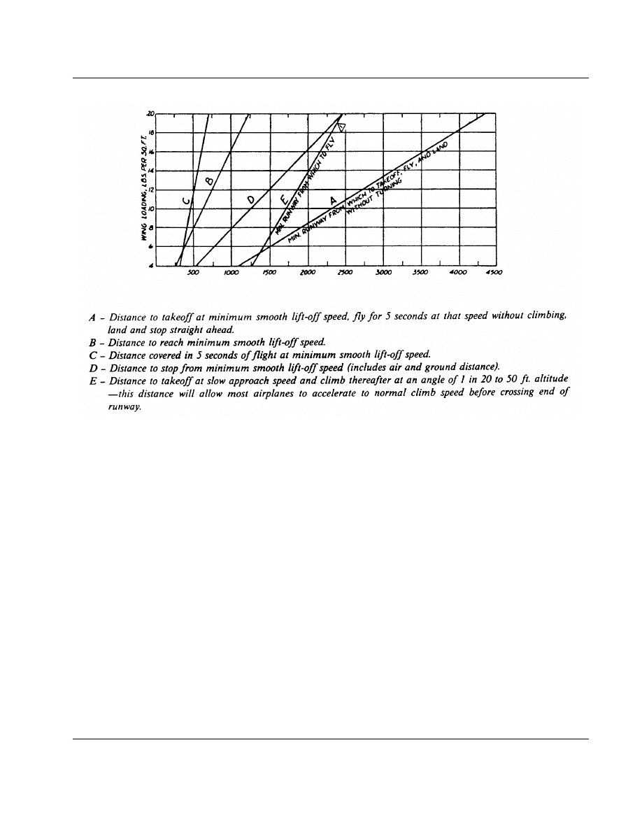
To determine an appropriate runway, use
the chart in figure 1 (sea-level elevation), or the fol-
lowing rule-of-thumb:
c.
The ideal runway at sea-level elevation
should be at least 4,000 feet long and 100 feet wide.
For each 1,000 feet increase in field elevation, add
500 feet to the runway length. If testing a high
performance aircraft, the airport’s runway at sea-
level should be more than 6,000 feet long and 150
feet wide to allow a wider margin of safety. Other
considerations, such as power to weight ratio, wing
design, and density altitude, also should be factored
into the equation for picking the best runway for
the initial flight testing.
3
5/24/95
AC 90-89A
Take-off Distance in Feet
FIGURE 1.
Runway Length Chart
d.
Identify emergency landing fields located
within gliding distance from anywhere in the airport
pattern altitude. Since engine failures are second only
to pilot error as the major cause of amateur-built
aircraft accidents, preparations for this type of emer-
gency should be a mandatory part of the FLIGHT
TEST PLAN.
e.
It is advisable to perform flight tests from
an airport with an active unicom or tower, even if
the aircraft does not have an electrical system or
is not equipped with a radio. Even at an uncontrolled
field, a communications base should be improvised.
For both situations, a hand held radio with aviation
frequencies and a headset with a mike and a push-
to-talk switch on the stick/yoke is recommended.
Good radio communications improves the overall
level of safety and reduces cockpit workload.
f.
The FAA recommends airport selection cri-
teria include the availability of hangar space and
ramp areas. These facilities will provide protection
from inclement weather and vandalism while the air-
craft is being tested, maintained, and inspected.
g.
The airport should have a telephone and
fire fighting equipment, the latter being in compli-
ance with relevant municipal codes (e.g., fire codes).
h.
Explain the Flight Test Program and
EMERGENCY PLANS to the airport manager or
owner. They may be able to assist the amateur-
builder in obtaining temporary hangar space, provid-
ing ground/air communications, and supplying emer-
gency equipment for use during the flight test.
4
5/24/95
AC 90-89A
SECTION 3.
EMERGENCY PLANS AND EQUIPMENT
‘‘The object of the game, gentlemen, is not to cheat death: the object is not to let him play.’’ Patrick
Poteen, Sgt. U.S. Army
1.
OBJECTIVE.
To develop a FLIGHT TEST
PLAN which contain two sets of emergency plans;
one for IN-FLIGHT emergencies and another for
GROUND emergencies.
a.
The IN-FLIGHT emergency plan should
address the following:
(1)
Complete engine failure or partial fail-
ure, especially after take off
(2)
Flight control problems and severe out-
of-rig conditions
(3)
Fire in the engine compartment or
cockpit
b.
The GROUND EMERGENCY plan should
be developed to train the ground crew and/or the
airport fire department crash crew on the following:
(1)
The airplane canopy or cabin door
latching mechanism
(2)
The pilot’s shoulder harness/seat belt
release procedure
(3)
The location and operation of the fuel
shut-off valve
(4)
The master switch and magneto/igni-
tion switch location and OFF position
(5)
Engine cowling removal procedures to
gain access to the battery location or for fire fighting
(6)
The battery location and disconnect
procedures
(7)
Fire extinguisher application and use
(8)
How to secure the ballistic parachute
system
c.
Ground Crew. Every test of an amateur-
built aircraft should be supported by a minimum
ground crew of two experienced individuals. The
ground crew’s function is two-fold:

5
5/24/95
AC 90-89A
(1)
To ensure that the aircraft is in air-
worthy condition for safe operation
(2)
To provide assistance to the test pilot
in an emergency
d.
The Airport.
(1)
If the airport does not have a fire rescue
unit, it is suggested the ground crew have a four
wheel drive vehicle equipped with a portable radio,
first aid kit, metal-cutting tools, and a fire extin-
guisher. A minimum of one person should be trained
in first-aid.
(2)
If the airport provides a fire rescue unit,
the test pilot should ensure the rescue unit and the
ground crew are trained and competent in performing
ground emergency functions as identified in the
FLIGHT TEST PLAN.
(3)
Suggestion.
For a small donation,
some local volunteer fire and rescue companies will
provide the amateur-builder with a standby crew dur-
ing the initial critical portions of the flight test phase.
e.
Hospital Location. The ground crew should
know the location and telephone numbers of the hos-
pitals and fire rescue squads in the vicinity of the
airport AND the flight test area. If the test pilot is
allergic to specific medications, or has a rare blood
type, a medical alert bracelet or card should be car-
ried or worn to alert medical personnel of the condi-
tion.
f.
Fire Extinguisher. Fire extinguisher’s
should be available to the ground crew, and a fire
extinguisher should be securely mounted in the cock-
pit within easy reach of the test pilot. A fire axe,
or other tool capable of cutting through the canopy,
also should be positioned in the cockpit.
g.
Fire Protection. There is always danger of
a flash fire during test flights. To prevent burns, the
pilot should wear an aviation/motorcycle helmet,
NOMEX coveralls/gloves and smoke goggles. If
NOMEX clothing is not available, cotton or wool
clothing will offer some protection from heat and
flames. Pilots should never wear nylon or poly-
ester clothing because synthetic materials melt
when exposed to heat and will stick to the skin.
h.
Pilot Protection. A modern aviation/motor-
cycle helmet, a properly installed shoulder harness,
a well designed seat, a clean cockpit design free of
protruding components/sharp edges, NOMEX cloth-
ing, smoke goggles, and a memorized emergency
plan ensure safety during flight testing.
i.
Parachute. The decision to wear a parachute
depends on the type of aircraft being tested. Some
aircraft have forward hinged canopies that are not
equipped with quick release pins or have pusher
propellers which increase the chance of injury to the
pilot while exiting the aircraft. Other aircraft designs
may pose no exit problems. If the decision is made
to wear a parachute, check that it has been recently
packed (within 120 days) by a qualified parachute
rigger. Ensure that the chute has not been exposed
to rain/moisture and when worn, does not interfere
with cockpit management. The test pilot should be
thoroughly trained on how to exit the aircraft and
deploy the parachute.
j.
Ballistic Chutes. Ballistic chutes are the lat-
est development in dealing with in-flight emer-
gencies. A ballistic chute is attached to the aircraft
and when activated, lowers the whole aircraft and
the pilot to the ground at the rate of descent of
approximately 20 feet per second.
(1)
Deployment Scenarios:
(i)
structural failure
(ii)
mid-air collision
(iii)
stall/spin
(iv)
loss of control/icing
(v)
engine failure over bad terrain
(vi)
pilot incapacitation
(2)
Installation Considerations: The
builder should consider the following when installing
a ballistic chute:
(i)
Matching the chute with the air-
craft’s size, weight, and V
ne
speed (check with the
chute manufacturer)
(ii)
How the chute will be positioned
and mounted
(iii)
The chute’s effect on the air-
craft’s weight and balance before deployment and
aircraft’s touchdown attitude after deployment
(iv)
Compatibility of the opening
loads and the aircraft’s structural design limits

6
5/24/95
AC 90-89A
(v)
The routing of the bridle and
harness
(vi)
The routing of the activating
housing
(vii)
The placement of the activating
handle in the cockpit
(viii)
Incorporation of chute deploy-
ment procedures in the in-flight emergency plan and
emergency check list
(ix)
The deployment time, from
activation to full chute opening
(3)
If a ballistic chute is installed, the
builder should add the appropriate ballistic chute
inspection items to the aircraft’s pre-flight inspec-
tion check list. The builder also should add the
ballistic chute manufacturer’s repack/refitting sched-
ule and maintenance inspections to the flight manual
and the conditional annual inspection check list.
SECTION 4.
TEST PILOT
‘‘We are looking for a few good Men and Women!’’ Marine Corps advertisement (1991)
1.
OBJECTIVE.
To select a qualified individual
to be the test pilot.
2.
GENERAL.
The test pilot should be com-
petent in an aircraft of similar configuration, size,
weight, and performance as the aircraft to be tested.
If the aircraft’s builder is the test pilot, the costs
involved in maintaining pilot competence should be
budgeted with the same level of commitment and
priority that is assigned to plans and materials to
complete the project.
3.
TEST PILOT REQUIREMENTS.
a.
A test pilot should meet the following mini-
mum qualifications:
(1)
Physically fit: Test flying an aircraft is
a stressful and strenuous task
(2)
No alcohol or drugs in the last 24 hours
(3)
Rated, current, and competent in the
same category and class as the aircraft being tested
(4)
Current medical and biennial or flight
review as appropriate, or a current USUA certifi-
cation and flight review
b.
Suggested Test Pilot Flight Time Require-
ments.
The following suggested number of flight
hours are only an indication of pilot skill, not an
indicator of pilot competence. Each test pilot must
assess if their level of competence is adequate or
if additional flight training is necessary. If an individ-
ual determines they are not qualified to flight test
an unproven aircraft, someone who is qualified must
be found.
(1)
100 hours solo time before flight test-
ing a kit plane or an aircraft built from a time-proven
set of plans
(2)
200 hours solo time before flight test-
ing for a ‘‘one of a kind’’ or a high performance
aircraft
(3)
A minimum of 50 recent takeoffs and
landings in a conventional (tail wheel aircraft) if the
aircraft to be tested is a tail dragger
c.
The test pilot should:
(1)
Be familiar with the airport and the
emergency fields in the area
(2)
Talk with and, if possible, fly with a
pilot in the same kind of aircraft to be tested
(3)
Take additional instruction in similar
type certificated aircraft. For example, if the aircraft
to be tested is a tail dragger, a Bellanca Citabria
or Super Cub is appropriate for training. For testing
an aircraft with a short wing span, the Grumman
American Yankee or Globe Swift is suitable for
training.
(4)
Be considered competent when they
have demonstrated a high level of skill in all planned
flight test maneuvers in an aircraft with performance
characteristics similar to the test aircraft

7
5/24/95
AC 90-89A
(5)
Study the ground and in-flight emer-
gency procedures developed for the aircraft and prac-
tice them in aircraft with similar flight characteristics
(6)
Have logged a minimum of 1 hour of
training in recovery from unusual attitudes within
45 days of the first test flight
(7)
If appropriate, have logged a minimum
of 10 tail wheel take-off and landings within the past
30 days
(8)
Study the performance characteristics
of the aircraft to be tested. Refer to the designer’s
or kit manufacturer’s instructions, articles written by
builders of the same make and model aircraft, and
study actual or video tape demonstrations of the air-
craft.
(9)
Review the FAA/National Transpor-
tation Safety Board (NTSB)/EAA accident reports
for the same make and model aircraft to be aware
of problems the aircraft has experienced during pre-
vious operations (see appendix 2 for the address).
(10)
Memorize the cockpit flight controls,
switches, valves, and instruments. A thorough
knowledge of the cockpit will result in controlled
and coordinated mental and physical reactions during
emergencies.
NOTE: The EAA has developed a Flight
Advisor Program which offers builders/
pilots assistance in performing a self evalua-
tion of the flight test program and/or selec-
tion of the test pilot. To obtain additional
information, contact a local EAA Chapter
or EAA Headquarters, (414) 426-4800.
SECTION 5.
MEDICAL FACTS FOR PILOTS
‘‘If the pilot is unairworthy, so is the airplane!’’ Bill Chana, Aeronautical Engineer
1.
OBJECTIVE.
To identify some of the well
known medical causes for aircraft accidents and to
stress the importance of a personal pre-flight check-
list in addition to an aircraft pre-flight checklist.
a.
Alcohol. FAR Part 91, ‘‘General Operating
and Flight Rules,’’ § 91.17 requires that 8 hours
must elapse from the last drink to the first flight.
Test flying an aircraft, however, places additional
mental and physical demands on the pilot. The FAA
strongly recommends a minimum of 24 hours
between the last drink and the test flight. This is
because small amounts of alcohol in the blood stream
can affect judgement, reaction time, and decrease a
pilot’s tolerance to hypoxia.
b.
Anesthetics. Local and dental anesthetic can
affect a pilots performance in many adverse ways.
It is recommended that a minimum of 48 hours
elapse from the time of anesthesia to the time the
pilot climbs into the cockpit.
c.
Blood Donations. Do not fly for 3 weeks
after donating blood. The body needs approximately
three weeks for a complete physiological recovery.
Although the physical affects may not be noticeable
at sea level, they will become apparent when flying
at higher altitudes.
d.
Carbon Monoxide (CO). CO is a colorless,
odorless, tasteless gas that is always present in
engine exhaust fumes. Carbon monoxide prevents
oxygen absorption by the blood, and exposure to the
gas creates vision problems, headaches, disorienta-
tion, and blurred thinking (see chapter 1, section 7,
paragraph 3 (g) for testing the aircraft for CO
contamination).
e.
Drugs. Similar to alcohol, drugs will reduce
or impair judgement and affect reflexes and hand/
eye coordination. It is a given that the use/abuse of
illegal drugs is dangerous and against the law.
Prescription drugs and over-the-counter remedies,
however, also may be dangerous when combined
with flying. The FAA recommends all pilots who
must take medication consult with an Aviation Medi-
cal Examiner (AME) to understand the medication’s
affects on their ability to think and react while in
the cockpit.
f.
Ear and Sinus Pain.
(1)
Ear and sinus pain is usually caused
by the eardrum or sinuses failing to equalize the air
pressure during a descent. The blocked ears and
sinuses can be caused by a head cold. The pain can
be considerable and is most noticeable during

8
5/24/95
AC 90-89A
descents. For ear blockages try yawning, swallowing,
or chewing gum which may give some relief. The
Valsalva procedure can be effective: pinch the nose,
close the mouth, and try to force air through the
nostrils.
(2)
If ear blockage occurs during flight, try
climbing back to a higher altitude (lower air pres-
sure) until the pain lessens. Then begin a gradual
rate of descent, allowing the ears and sinuses time
to adapt to the increasing pressure.
(3)
After landing, nasal sprays will give
some sinus pain relief. To relieve ear pain, try wet-
ting paper towels with hot water, put the towels in
the bottom of a plastic or dixie cup and then hold
the cups over the ears. The warmth will help ease
the inflamed tissues and reduce the pain. If pain
continues, see a doctor.
NOTE: The best way to avoid this problem
is not to fly with a head cold, upper res-
piratory infection, or nasal allergic condi-
tion. Be advised that some nasal and oral
decongestants could be ineffective at altitude
and have side effects such as drowsiness that
can significantly impair pilot performance.
Again, consult with an Aviation Medical
Examiner to understand the affects of medi-
cation before flying.
g.
Fatigue. Fly only when healthy, fit, and
alert. Mental and physical fatigue will generally slow
down a pilot’s reaction time, affect decision making,
and attention span. Lack of sleep is the most common
cause of fatigue, but family and business problems
can create mental fatigue which can have the same
effects on the pilot as lack of sleep.
h.
Flicker Vertigo. Light, when flashing at a
frequency between 4 to 29 cycles per second, can
cause a dangerous physiological condition in some
people called flicker vertigo. These conditions range
from nausea and dizziness to unconsciousness, or
even reactions similar to an epileptic fit. When head-
ing into the sun, a propeller cutting the light may
produce this flashing effect. Avoid flicker vertigo,
especially when the engine is throttled back for land-
ing. To alleviate this when the propeller is causing
the problem, frequently change engine revolutions
per minute (rpm). When flying at night and the rotat-
ing beacon is creating flicker vertigo, turn it off.
i.
Underwater Diving. Never fly immediately
after SCUBA diving. Always allow 24 hours to
elapse before flying as a pilot or a passenger in order
to give the body sufficient time to rid itself of exces-
sive nitrogen absorbed during diving.
j.
Stress. Stress from the pressures of a job
and everyday living can impair a pilot’s perform-
ance, often in subtle ways. A test pilot may further
increase the stress level by setting unreasonable test
flying schedules in order to meet an arbitrary ‘‘be
done by date.’’ Stress also may impair judgement,
inducing the pilot to take unwarranted risks, such
as flying into deteriorating weather conditions or fly-
ing when fatigued to meet a self imposed deadline.
9
5/24/95
AC 90-89A
SECTION 6.
TRANSPORTING THE AIRCRAFT TO THE AIRPORT
‘‘Best laid plans of mice and men are often stuck in traffic.’’ Ben Owen, EAA Executive Director (1994)
1.
OBJECTIVE.
To reduce damaging the air-
craft in transit. The following suggestions may pre-
vent this from happening:
a.
Use a truck or flat bed truck/trailer large
enough to accommodate the aircraft and the addi-
tional support equipment.
b.
If the aircraft wings are removable, build
padded jigs, cradles, or fixtures to hold and support
them during the trip to the airport.
c.
Secure the fixtures to the truck/trailer, then
secure the wings to the fixture.
d.
Use two or more ropes at each tie down
point.
e.
Use heavy moving pads used for household
moves to protect wings and fuselage. Most rent-a-
truck firms offer them for rental.
f.
During the planning stage, obtain
applicable permits and follow the local ordinances
for transporting an oversized load. Ask the local
police if they can provide an escort to the airport.
g.
Brief the moving crew thoroughly before
loading and unloading the aircraft.
h.
Ensure the designated driver has recent
experience driving a truck/trailer and is familiar with
the roads to the airport.
10
5/24/95
AC 90-89A
SECTION 7.
ASSEMBLY AND AIRWORTHINESS INSPECTION
‘‘Complacency is one of the major causes of accidents, no matter how well things are going, something
can go wrong’’ Art Scholl
1.
OBJECTIVE.
To determine the airworthiness
of the aircraft and its systems.
2.
GENERAL.
a.
If the aircraft must be reassembled after
being moved to the airport -- take time to do so
carefully. This is a critical event because mistakes
can easily be made due to the builder’s preoccupation
with the impending first flight of the aircraft. One
of the most common and deadly mistakes is to
reverse the rigging on the ailerons. To prevent errors
in reassembling the aircraft, follow the designer’s
or kit manufacturer’s instructions, or use a written
check list specifically designed as part of the
FLIGHT TEST PLAN. At the completion of each
major operation, have another expert check the work.
b.
When the aircraft is reassembled, perform
a pre-flight ‘‘fitness inspection.’’ This inspection
should be similar in scope and detail to an annual
inspection. The fitness inspection should be accom-
plished even if the aircraft has just been issued a
special airworthiness certificate by the FAA. Even
if a builder was 99 percent perfect and performed
10,000 tasks building the aircraft, there would still
be a hundred items that would need to be found and
corrected before the first flight.
3.
FITNESS INSPECTION - AIRFRAME.
The following additional safety check list items may
not be applicable to all amateur-built make and
model aircraft, but are presented for consideration
and review:
a.
Control stick/wheel: The control stick/
wheel should have a free and smooth operation
throughout its full range of travel. There should be
no binding or contact with the sides of the fuselage,
seat, or instrument panel. There should be no free-
play (slack) in the controls, nor should the controls
be tight as to have stick-slip movement.

11
5/24/95
AC 90-89A
b.
Rudder pedals: Move the rudder pedals
through the full range of travel. The pedal movement
should be smooth with no binding. The test pilot
should ensure that their shoes will not catch on
exposed metal lines, fixtures, or electrical wire har-
ness.
c.
Brakes: Hand and/or toe brake pressure
should be firm with no tendency to bleed down or
lock up. Spongy brakes that must be ‘‘pumped up,’’
or show a drop in the level of brake fluid in the
reservoir after a few brake applications, indicate a
brake fluid or air leak in the system.
d.
Main landing gear: Ensure that the gear
attach points, shimmy dampener, bungees, wheels,
brakes, and wheel fairings are airworthy. If
applicable, check that the tail wheel pivot point is
centered and vertical in relation to the longitudinal
axis of the aircraft. It is critical that the main landing
gear alignment toe in/toe out is zero or matches the
specifications for fuselage/landing gear alignment
called out in the plans. Even one landing gear wheel
out of alignment can cause a ground loop.
e.
Control surfaces: Perform rigging checks to
ensure that control input for ailerons, rudder, ele-
vators, and trim tabs results in the correct amount
of travel and direction of the control movement and
that contact with the stops is made. Also ensure that
the flaps, if installed, have the proper travel, operate
as a single unit, and cannot be extended beyond the
maximum extended position. It is important to ensure
that the control cable tension is correct by checking
it with a calibrated tensiometer and confirming that
all the attachment hardware is secured and safety-
wired.
(1)
If the cable tension is less than the
specifications require, the ‘‘in flight’’ air loads dur-
ing flight will prevent full travel of the control, even
if the control has the right amount of deflection and
hits all the stops in the cockpit/wing/tail when tested
on the ground. With low cable tension, the desired
control movement input will be absorbed by the slack
in the cables.
(2)
While checking cable tension, make
sure there is no ‘‘free play’’ in the flight control
hinges and rod ends. Free play and loose cable ten-
sion combined with control mass imbalance sets the
stage for the onset of control surface ‘‘flutter.’’ Do
not, however, rig the controls at too high a cable
tension. This will cause high wear rate on the pulleys
and prevent good control feel, especially at low air-
speeds.
f.
Instrument panel: All the instruments
should be properly secured in the panel and have
preliminary markings on them. Airspeed indicator
and engine tachometer should be marked with the
EXPECTED performance range markings. Oil
temperature and oil pressure must have the engine
manufacturer’s recommended operating range
marked. If the markings are on the instrument glass
face, paint a white slippage mark on both the glass
and on the instrument case to alert the pilot in case
the glass/range marks have moved. Attach a tem-
porary placard to the instrument panel with the
expected stall, climb, and glide speeds. It is a handy
reference in times of emergency.
g.
Behind the instrument panel: Very few
amateur-built aircraft of the same make and model
have the same instrument panel design. Each ama-
teur-builder should inspect this area to ensure that
all line connections are tight, that nothing interferes
with control travel, and there are no loose wires or
fuel, oil, or hydraulic leaks.
h.
Carbon Monoxide: Carbon Monoxide leaks
also can be performed. Wait until night or put the
aircraft in a dark hangar. Climb into the cockpit and
have a friend shine a bright flood light close to the
fire-wall. If light leaks into the cockpit, carbon mon-
oxide can seep in. Mark it and seal it.
i.
Engine and propeller controls: All controls
should be visually inspected, positive in operation,
and securely mounted. The friction lock on both con-
trols should be checked for operation. Each control
should have full movement with at least a
1
⁄
4
inch
of ‘‘cushion’’ at the full travel position. The control
cables should be firmly attached to the fuselage along
each 24 inches of their runs to prevent whipping
of the cable and loss of cable movement at the other
end. Control cables with ball sockets should have
large area washers on either end of the bolt connec-
tion. This will ensure the control will remain con-
nected, even if the ball socket fails and drops out.
j.
Static system: The best procedure to check
the altimeter for leaks and accuracy is to have the
entire static system checked in accordance with FAR
Part 43, appendix E, at an FAA-approved repair sta-
tion.

12
5/24/95
AC 90-89A
4.
FIELD CHECK.
Two people are needed to
accomplish the following field check that will enable
an amateur-builder to detect if the aircraft’s
instrument system is leaking: (Note: This field check
is not an accuracy check.)
a.
Airspeed check: Slip a long rubber hose
over the pitot mast (surgical tubing is recommended).
As one person reads the airspeed, the other should
very slowly roll up the other end of the tubing. This
will apply pressure to the instrument. When the air-
speed indicator needle reaches the aircraft’s approxi-
mate recommended cruise speed, pinch the hose shut,
and hold that reading. The airspeed needle should
remain steady for a minute if the system is sound.
A fast drop off will indicate a leak in the instrument,
fittings, lines, or the test hose attachment. NEVER
force air in the pitot tube or orally apply suction
on a static vent. This will cause damage to the
instruments.
b.
Altimeter/vertical speed check.
(1)
To check the static side, apply low suc-
tion at the end of the static vent port. The easiest
way to gain access to the static system is to remove
the static line at the static port. If there are two static
ports, tape the unused port closed. Next, get two feet
of surgical tubing, seal one end, and tightly roll it
up. Attach the open end to the static line and slowly
unroll the tubing. This will apply a suction, or low
pressure, to the static system.
(2)
The altimeter should start to show an
increase in altitude. The vertical speed indicator also
should indicate a rate of climb. The airspeed may
show a small positive indication. When the altimeter
reads approximately 2,000 feet, stop and pinch off
the tube. There will be some initial decrease in alti-
tude and the vertical speed will read zero. The altim-
eter should then hold the indicated altitude for at
least a minute. If altitude is lost, check for leaks.
(3)
IMPORTANT: The above airspeed and
altimeter field checks should not be considered the
equivalent of airspeed or static system accuracy tests
as certified by a certificated repair station, but a
check of the system for possible leaks. These checks
do not take into consideration the pitot tube and static
ports located on the airframe. The FAA recommends
the builder not deviate from the designer’s original
plans when installing the pitot and static system.
c.
Fuel system: Since 1983, more than 70 per-
cent of the engine failures in amateur-built aircraft
were caused by fuel system problems. Many times
the direct cause of engine failure was dirt and debris
in the fuel tank and lines left behind during the manu-
facturing process.
(1)
Before the aircraft’s fuel tanks are
filled, the amateur-builder should vacuum any manu-
facturing debris from each tank and wipe them down
with a ‘‘tack’’ cloth (available from a paint supply
store). Next, the system should be flushed with avia-
tion grade gasoline several times in order to remove
any small or hard to reach debris from the tanks
and lines. The fuel filter/gasolator screen/carburetor
finger screen should also be cleaned. The amount
of time spent ‘‘sanitizing’’ the fuel system will pro-
vide big safety dividends for the life of the aircraft.
(2)
When filling the tanks, place the air-
craft in the straight and level cruise position. Add
fuel in measured amounts to calibrate the fuel tank
indicators. While allowing the aircraft to sit for a
short time to observe for possible leaks, inspect the
fuel tank vents to see if they are open and clear.
Check that the fuel tank caps seal properly. If there
are no leaks and the fuel system has an electric boost
pump, pressurize the system and again check for
leaks. The fuel selector, vents and fuel drains should
be properly marked and tested for proper operation.
NOTE: Many amateur-built aircraft take 5
to 8 years to build. During that time, many
rubber-based oil and fuel lines and cork gas-
kets that were installed early in the building
process may have age hardened, cracked,
and/or turned brittle. The builder should
carefully inspect these components and
replace as necessary to prevent a premature
engine failure.
d.
Hydraulic system: The hydraulic system
should function dependably and positively in accord-
ance with the designer’s intent. Retractable landing
gear should be rigorously cycled on the ground,
using both the normal and emergency landing gear
extension system.
e.
Safety belt and shoulder harness: These
items should be checked for condition and proper
installation. A review of amateur-built aircraft
accidents has disclosed a significant number of
accidents in which the seat belt mounting hard points

13
5/24/95
AC 90-89A
failed. Each seat belt and shoulder harness mounting
hard point should be built to the designer’s specifica-
tions to ensure that it will hold the harness and pilot
in the aircraft at the ultimate design ‘‘G’’ load speci-
fication, both positive and negative, for the aircraft.
f.
Avionics and electrical checks: Test the avi-
onics systems. Perform an operational check to
ensure the radio(s) transmit and receive on all fre-
quencies. Inspect circuit breakers/fuses, micro-
phones, and antennas for security and operation. Test
the ELT for proper operation and battery life. Elec-
trical systems can be checked for operation of lights,
instruments, and basic nav/comm performance.
Other electrical systems, such as generator/alternator
output can be checked during the engine run-ins, taxi,
and flight tests. Check the battery and the battery
compartment for security and if applicable, ensure
that the battery is properly vented to the outside of
the aircraft. Check the condition of the engine to
airframe bonding (grounding) wire. Ensure that all
electrical instruments operate properly.
g.
Cowling and panel checks: Ensure that all
inspection panels are in place, the cowling is secured,
and cowl flap operation is satisfactory. Inspect the
propeller spinner and its backing plate for cracks.
h.
Canopy/door locks checks: Ensure the can-
opy or doors on the aircraft work as advertised. Dou-
ble check the canopy or door lock(s) so the canopy
and doors will not open in flight and disturb the
airflow over the wings and stall the aircraft. If a
canopy jettison system is installed, check for proper
operation when the aircraft on the ground and when
it is on jacks. (Jacks will simulate flight loads on
the aircraft.)
14
5/24/95
AC 90-89A
SECTION 8.
WEIGHT AND BALANCE
‘‘Never argue with your spouse or a mathematician’’ Phil Larsh, Accident Prevention Counselor,
Colfax IN (1994)
1.
OBJECTIVE.
To discuss the importance of
developing an accurate weight and balance calcula-
tions for both test and recreational flights. Additional
information on weight and balance can be found in
AC 91-23A, Pilot’s Weight and Balance Handbook.
a.
A good weight and balance calculation is
the keystone of flight testing. Accurately determining
the aircraft’s take-off weight and ensuring that the
center of gravity (CG) is within the aircraft’s design
for each flight is critical to conducting a safe flight
test.
b.
An aircraft should be level when weighed,
spanwise and fore and aft in accordance with the
manufacturer’s instructions, and should be in the
level flight position. It is highly recommended that
the weighing be done in an enclosed area, using three
calibrated scales. Bathroom scales are not rec-
ommended because they are not always accurate.

15
5/24/95
AC 90-89A
ITEMS
WEIGHT (LBS)
ARM (INCHES)
MOMENT (IN-LBS)
Left Wheel
Right Wheel
Tail Wheel
TOTALS
101
99
42
242
60
60
180
80.8
6060
5940
7560
19560
TOTAL MOMENT = Empty weight CG or 19560 = 80.8
TOTAL WEIGHT
242
FIGURE 2.
EMPTY WEIGHT CG
2.
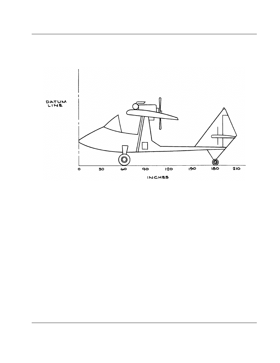
DETERMINING EMPTY WEIGHT CG.
a.
The sample airplane for determining empty
weight is a single seater, which the kit manufactur-
er’s design empty weight of 253 pounds and a gross
weight limit of 500 pounds. The datum line is located
at the nose of the aircraft and the CG range is
between 69 to 74 inches from the datum.
b.
To work a CG problem, figure the EMPTY
WEIGHT CG first. On a piece of paper draw four
blocks. Title each block from left to right as shown
in figure 3.
(1)
Under the block titled item, vertically
list ‘‘left wheel,’’ ‘‘right wheel,’’ and ‘‘nose/tail
wheel.’’
(2)
Place a calibrated scale under each
wheel and record the weight on each gear, in pounds,
in the weight block along side the appropriate wheel.
This process is done with an empty fuel tank.
(3)
Measure in inches the distance from the
datum line, or imaginary point identified by the
manufacturer (e.g., nose of the aircraft), to the center
line (C/L) of the three wheels. Record the distance
of each wheel and place it in the moment arm block
beside the appropriate wheel (see figure 2).
(4)
Multiply the number of inches (arm)
by the weight on each wheel to get the moment (inch-
pounds) for each wheel. Add the weight on the three
gears and the three moments in inch pounds and
divide the total weight into the total moment. The
sum is the ‘‘EMPTY WEIGHT CENTER OF
GRAVITY’’ in inches. In the sample case, the empty
weight CG is 80.8.
NOTE: All calculations should be carried
out to two decimal places.

16
5/24/95
AC 90-89A
ITEMS
WEIGHT (LBS)
ARM (INCHES)
MOMENT (IN-LBS)
A/C
Pilot
Fuel
TOTALS
242
170
30
442
80.8
65
70
74
19560
11050
2100
32710
TOTAL MOMENT = Takeoff CG or 32710 = 74
TOTAL WEIGHT
442
FIGURE 3.
TAKE-OFF CG
3.
DETERMINING TAKE-OFF WEIGHT CG.
a.
Since the aircraft’s empty weight and empty
weight CG are fixed numbers, the only way an air-
craft’s CG can be changed is by adding weight in
other locations.
b.
For example, in figure 3, the aircraft’s
empty weight has been written in the appropriate
blocks. The pilot weighs 170 pounds and fuel (5 gal-
lons) weighs 30 pounds.
c.
Again, all measurements are made from the
datum to the center line of the object that has been
added. Weight multiplied by inches from the datum
equals moment. Add the weights and moments to
find the take-off CG for that particular flight.
d.
Loaded in this configuration, the aircraft
is within the CG flight envelope and is safe to fly.

17
5/24/95
AC 90-89A
ITEMS
WEIGHT (LBS)
ARM (INCHES)
MOMENT (IN-LBS)
A/C
S/B
Pilot
Strobe
Fuel
Fuel
TOTALS
242
15
170
1.5
30
1.5
460
80.8
75
65
179
70
55
74.3
19560
1125
11050
268.5
2100
82.5
34186
TOTAL MOMENT = Alteration Takeoff Weight CG or 34186 = 74.3
TOTAL WEIGHT
460
FIGURE 4.
ADDITIONAL EQUIPMENT ADDED
4.
ADDING ADDITIONAL EQUIPMENT.
a.
During flight testing, a strobe battery and
hand held radio are added. The battery/battery box
weight is 15 pounds and the location is 75 inches
aft of the datum; the strobe assembly weight is 1.5
pounds and is located 179 inches aft of the datum;
the radio’s weight is 1.5 pounds and is located 55
inches aft of the datum (see figure 4).
b.
In the sample problem, the previous figures
for take-off weight and moment are still accurate,
hence those numbers have been listed in the appro-
priate blocks.
(1)
Add the battery, strobe, and radio num-
bers in the appropriate locations and calculate the
totals. At 465 pounds, the aircraft is still 35 pounds
under its design gross weight limit of 500 pounds
but is out of balance because the CG has moved
.3 inches further aft (74.3 inches) than the allowable
rear CG limit of 74 inches.
(2)
Since the aircraft is out of balance with
an aft CG, it is no longer 100 percent stable in pitch
and would be dangerous to fly. In most cases, it
is not the amount of weight added to the aircraft
that can cause a major safety problem but its loca-
tion.
(3)
To bring this aircraft back into the safe
CG range, the battery would have to be moved 9
inches forward (66 inches from the datum line).
Another alternative is to install 8 pounds of ballast
in the nose (20 inches from the datum).
(4)
If the sample aircraft exceeded the
designer’s gross weight limit (e.g., 300 pound pilot)
instead of the CG limit, its climb, stall, and perform-
ance capability would be poor and the possibility
for in-flight structural failure would be high.
NOTE: In the sample weight and balance,
positive numbers were chosen by placing the
datum line on the nose of the aircraft. Some
manufacturers prefer to use a datum located
somewhere between the aircraft’s nose and
the leading edge of the wing.
(5)
This kind of datum will set up a system
of positive arms (items located aft of the datum) and
negative arms (items located forward of the datum).
(6)
When working a weight and balance
problem with negative and positive moments, sub-
tract the sum of all negative moments from the sum
of all positive moments to reach a ‘‘total moment’’
for the aircraft.
18
5/24/95
AC 90-89A
SECTION 9.
PAPERWORK
‘‘It is harder to write a lie in a logbook than tell one, because your eyes see it and your fingers feel
it.’’ Bob Moorman, Ultralight Instructor (1994)
1.
OBJECTIVE.
To have the proper documenta-
tion and paperwork to conduct the flight test.
a.
Weight and Balance: The weight and bal-
ance for the aircraft should be carefully done. The
gross weight and CG range should be determined
prior to every flight.
b.
Airworthiness/Registration/Operating
Limitations/Placards/Weight and Balance: Must be
on board, or the aircraft is not legal to be operated.
c.
Checklists: In addition to the assembly/air-
worthiness checklist previously discussed in section
7, the builder should prepare the following check-
lists: preflight; take-off/cruise; before starting;
descent/before landing; starting the engine; after
landing; before takeoff; securing the aircraft; and
emergency procedures. A checklist to cover the
above procedures may seem a tedious task, but it
will only be the size of a 5x8 card -- similar to a
checklist for a Cessna 150 or a Piper PA-28-140.
NOTE: The amateur-builder should antici-
pate several revisions to the checklists.
d.
Flight Manual: It is imperative a flight
manual describing the anticipated performance of the
aircraft be written by the aircraft builder/kit manufac-
turer. The manual will be revised several times dur-
ing the flight test phase until it accurately reports
the aircraft’s performance.
e.
Maintenance Records (logbooks): Opera-
tors of amateur-built aircraft are required to only
record the yearly condition inspections in accordance
with the aircraft’s operating limitations. The FAA
recommends, however, that every amateur-built air-
craft/ultralight owner record in the aircraft’s
logbooks all inspections and maintenance performed.
This will create an aircraft’s maintenance history and
will be invaluable in spotting trends.
19
5/24/95
AC 90-89A
SECTION 10.
POWERPLANT TESTS
‘‘Don’t short-change the engine tests or you won’t be around to give your grandkids a ride.’’ Dick Koehler,
A&P Instructor (1994)
1.
OBJECTIVE.
To ensure that the engine has
been properly run-in and is safe to operate in all
rpm ranges.
a.
An engine pre-oil and cold compression test
can be conducted as follows:
(1)
Remove the rocker-box covers and one
spark plug from each cylinder.
(2)
Using an external oil pump, or by rotat-
ing the propeller in the direction of rotation, pump
a substantial supply of oil up from the sump into
the rocker arms.
(3)
When the engine is pre-oiled, run a
cold compression test of each cylinder.
(4)
The results will serve only as an initial
bench mark for comparing other compression tests
taken after the engine has been run-up to operating
temperature.
b.
New/newly overhauled engine run-in proce-
dures:
(1)
Most amateur-builders start with a new
or newly overhauled engine and proceed to ‘‘run it
in’’ on the airframe. This practice is followed due
to lack of access to a test cell or a special ‘‘club’’
propeller that is specifically designed to aid in engine
cooling during run-in. There are pros and cons to
using an airframe to run in an engine, but the best
advice has always been to follow the engine manu-
facturer’s instructions. These instructions are found
either in the manufacturer’s overhaul manuals, serv-
ice bulletins, or service letters. Following the manu-
facturer’s instructions is especially important if the
engine has chrome cylinders which require special
run-in procedures.
(2)
Also, before running-up the engine, be
certain that it has the proper grade oil in the sump.
Some new and newly overhauled engines are shipped
with a special preservative oil to prevent corrosion.

20
5/24/95
AC 90-89A
Drain this out and reservice the engine with the cor-
rect oil before starting.
c.
Used engine run-in procedures: Some ama-
teur-builders install a used engine from a flyable air-
craft. The same checks and adjustments used on a
new or newly overhauled engine should be con-
ducted. New and used engines require special
attention to engine cylinder baffling to ensure cyl-
inder cooling is within the engine manufacturer’s
cylinder head temperature specifications.
d.
Pre run-in checks:
(1)
Before beginning the powerplant tests,
inspect the engine and propeller carefully. All fuel
and oil line connections should be tight. Check the
torque on the engine mount attaching bolts. Be cer-
tain that there are no tools, hardware, or rags laying
between the cylinders or under the magnetos.
(2)
Check for the proper amount of oil in
the engine and that the dip stick gives an accurate
reading of the oil quantity. Be advised that some
engines were mounted on an angle in type certifi-
cated aircraft. These engines have a special part num-
ber oil dip stick, which corrects for the different
angle of oil in the crankcase. The same engine,
mounted level in a amateur-built aircraft with the
original dip stick, will not show the correct oil quan-
tity.
e.
Test and Support Equipment:
(1)
A cylinder head temperature gauge
(CHT) is needed to ensure that all cylinders are
receiving the proper flow of cooling air.
(2)
On the newer aircraft engines, the cyl-
inders are drilled and tapped to accept a bayonet
type of CHT thermocouple probes. For older engines,
the thermocouple is designed like a spark plug
washer and fits under a spark plug. It can be installed
in any cylinder, either under the top or bottom spark
plug.
(3)
Each type of CHT design can have
multiple thermocouples which are connected to a
selector switch in the cockpit. The pilot then selects
the cylinder he wants to monitor. This also is an
excellent troubleshooting tool for identifying fouled
plugs and bad ignition leads.
(4)
If there is only one CHT thermocouple,
attach it to the rearmost cylinder on the right side
of the engine (as viewed from the cockpit) and run-
up the engine. Run the same test on the opposite
rearmost cylinder to be certain the hottest running
cylinder was selected. Calibrated oil pressure and oil
temperature gauges also are needed to test the
accuracy of the engine instruments installed in the
aircraft.
(5)
The following support equipment is
needed: 50 feet or more of tie-down rope, tie-down
stakes, two chocks for each wheel, fire extinguisher,
assorted hand tools, safety-wire, cotter-pins, ear and
eye protection, grease pencils, logbooks, clip board,
pen and paper, a watch to time the tests, rags, and
manufacturer’s instructions.
f.
Safety Precautions: Before the first engine
run, ensure the aircraft is tied down, brakes on, and
the wheels are chocked. The builder and flight test
team should wear ear and eye protection. All flight
test participants should be checked out on fire extin-
guisher use and operation. During engine runs, do
not allow anyone to stand beside the engine, or in-
line or close to the propeller. Making minor adjust-
ments to a running engine, such as idle and mixture
settings, is a very dangerous procedure and should
be done with great care by experienced individuals.
g.
The First Engine Run:
(1)
The first start of the engine is always
a critical operation. The engine should be pre-oiled
in accordance with the manufacturer’s instructions.
For aircraft using other than FAA-approved oil pres-
sure and temperature gauges, the FAA recommends
attaching an external calibrated oil temperature and
pressure gauge to the 4 cycle engine in order to cali-
brate the engine instruments. After priming the
engine and completing the starting engine checklist
items, the first concern is to get an oil pressure read-
ing within the first 20 to 30 seconds. If there is no
oil pressure reading -- shut down.
(2)
There are three common problems that
would cause low or fluctuating oil pressure.
(i)
Air in the oil pressure gauge line:
This is easily fixed by loosening the line connection
near the oil pressure gauge and squirting oil into
the line until full. Another option is to use a pre-
oiler to provide the pressure and carefully bleed the
air out of the line near the oil gauge by loosening
the B-nut that connects the oil line to the gauge.

21
5/24/95
AC 90-89A
(ii)
A misadjusted oil pressure relief
valve: Cleaning the pressure relief ball, checking for
the proper number of washers, correcting spring ten-
sion, and re-adjusting the setting could solve the
problem.
(iii)
An internal problem within the
engine (most likely the oil pump): An engine tear
down would be required.
(3)
With good oil pressure/temperature
readings and the engine running smoothly, ensure
that the engine oil pressure and temperature gauges
in the cockpit match the calibrated oil pressure and
temperature gauges, which were attached to the air-
craft for the first run. Do not overlook this test. It
is critical to determine the accuracy of the cockpit
engine gauges not only for the ground engine run-
in period, but for in-flight engine cooling tests.
(4)
Work through the engine manufactur-
er’s run-in schedule. The majority of the engine
manufacturers recommend a series of engine runs
from low rpm to maximum rpm. Each run usually
incorporates a 200 rpm increase and lasts no longer
than 10 minutes. The secret to a successful engine
run is not to let the engine temperatures exceed
manufacture’s limits during engine runs.
NOTE: Engines with chrome cylinders or
chrome rings require different high power
run-in programs. Follow the manufacturer’s
run-in instructions to ensure the engine will
perform satisfactorily over its lifetime.
h.
Engine Cool Down: After a ground-run, the
cooling off period takes approximately an hour. This
is because a newly overhauled engine needs time
for the internal parts (e.g., rings, cylinders, valves,
bearings, and gear faces) to expand and contract sev-
eral times to obtain a smooth surface that retains
its ‘‘memory.’’ This is a lengthy process even when
done right, but it is important not to skip any of
the recommended runs to save time. To do so is
to risk increasing oil consumption and reducing over-
all engine performance, reliability, and engine life
span -- which could be costly in the long-term.
i.
Record the engine run-in data: During the
engine run, monitor the cylinder head temperatures,
oil temperature, and oil pressure. Record the readings
and adjustments for future reference. If the cylinder
head temperatures are rising close to the red line,
reduce power and stop the test. Some causes of high
cylinder head temperatures include using spark plugs
with the improper heat range; cylinder head tempera-
ture gauges installed on the wrong cylinder; missing
or badly designed cylinder head cooling baffles; par-
tially plugged fuel nozzles (applicable to fuel
injected engines); fuel lines of improper internal
diameter (creates lean mixtures); engine improperly
timed either mechanically and/or electrically; and the
carburetor fuel mixture set excessively lean.
j.
After shut-down:
(1)
After each engine run, check for fuel
and oil leaks, loose connections, and hot spots on
cylinders (burnt paint). The FAA recommends drain-
ing the oil and removing the oil screen/filter within
the first 2 hours of running the engine. Check the
screen/filter for ferrous metal with a magnet. Wash
and inspect the screen/filter for non-ferrous metal
like brass, bronze, or aluminum.
(2)
A very small quantity of metal in the
screen is not uncommon in a new or newly over-
hauled engine. It is part of the painful process of
‘‘running-in.’’ If subsequent oil screen checks
(2 hours apart) show the engine is ‘‘making metal,’’
this indicates a problem inside the engine and a tear
down inspection is required.
(3)
It also is recommended all fuel sumps,
filters, and gasolators be checked for debris after
each engine run. Special attention should be given
to the fuel system by the builder who constructed
fuel tanks out of composite or fiberglass materials.
Composite and fiberglass strands can be very fine,
making visual detection difficult. Frequent cleaning
of the fuel filters and screens early in the flight test-
ing phase will avoid a gradual build up of loose
composite fibers, which would reduce or stop the
flow of fuel to the engine.
22
5/24/95
AC 90-89A
SECTION 11.
ADDITIONAL ENGINE TESTS
‘‘Always go with the best fix not the cheapest fix.’’ Bill Deeth, Master Mechanic (1994)
1.
OBJECTIVE.
To determine if the engine sup-
ply of fuel is adequate at all angles of attack.
a.
Mixture and Idle Speed Check: After
completing the initial engine ‘‘run-in’’ tests, check
the idle speed and mixture settings. To determine
if the mixture setting is correct, perform the follow-
ing:
(1)
Warm up the engine until all readings
are normal
(2)
Adjust the engine rpm to the rec-
ommended idle rpm
(3)
Slowly pull the mixture control back
to idle cut-off
(4)
Just before the engine quits, the engine
rpm should rise about 50 rpm if the mixture is prop-
erly adjusted. If the rpm drops off without any
increase in rpm, the idle mixture is set too lean. If
the rpm increases more than 50 rpm, the idle mixture
is set too rich.
NOTE: Some amateur-builders, after prop-
erly setting the idle mixture/rpm to the
manufacturer’s specification, increase the
engine idle rpm by 100 rpm for the first 10
+ hours of flight testing. This is to ensure
that the engine will not quit when the throt-
tle is pulled back too rapidly, or when power
is reduced on the final approach to landing.
b.
Magneto Check:
(1)
The magneto checks should be smooth
and the difference between both magnetos rpm drops
should average about 50 rpm. The builder also
should perform a ‘‘HOT MAG’’ check, to ensure
against the engine, on its own, deciding when and
where to start. To perform a hot mag check, run
up the aircraft until the engine is warm. At idle rpm
turn the magneto switch off; the engine should stop
running. If the engine continues to run, one or both
of the magnetos is hot (not grounded).
(2)
The usual causes for a hot magneto are
a broken ‘‘P’’ lead coming out of the magneto or
a bad magneto switch. THIS IS AN IMMEDIATE

23
5/24/95
AC 90-89A
THREAT TO THE PERSONAL SAFETY OF ANY-
ONE NEAR THE AIRPLANE AND MUST BE
REPAIRED AT ONCE.
c.
Cold Cylinder Check:
(1)
If the engine is running rough and the
builder determines it may be an ignition problem,
perform the following check:
(i)
Run the engine on the bad mag-
neto for about 30 seconds at 1200 rpm. Without
switching the mag switch back to ‘‘both,’’ shut off
the engine.
(ii)
One of the test crew should
quickly use a grease pencil to mark an area of the
exhaust stacks approximately an inch from the flange
that attaches the stacks to the cylinders.
(iii)
Check the marks on the stacks. If
one or more of the exhaust stacks with a grease mark
has NOT been burned to a grayish-white color and
the mark on the stack still retains most of the original
color of the grease pencil, the ‘‘cold cylinder’’ has
been identified.
(2)
Probable causes of the cold cylinder
problem are defective spark plugs, ignition leads, or
a cracked distributor in one of the magnetos. To
detect if the spark plugs are bad, switch both plugs
to another cylinder. If the grease pencil proves the
problem moved to the new cylinder, the spark plugs
are bad. If the problem remains with the original
cylinder, the ignition lead or magneto is bad.
d.
Carburetor Heat:
(1)
It is strongly recommended that all
amateur-builders install a carburetor heat system that
complies with the engine manufacturer’s rec-
ommendation. If no recommendation is available, the
FAA suggests a carburetor heat system for a sea-
level engine and a conventional venturi should be
designed so that it will provide a 90 degrees F
increase in the venturi at 75 percent power. For alti-
tude engines using a conventional venturi carburetor,
120 degrees F increase in venturi temperature at 75
percent power will prevent or eliminate icing.
Remember: Too little carburetor heat will have no
effect on carburetor icing, and too much carburetor
heat will cause a overly rich mixture which will
reduce power and may shut down the engine.
(2)
During the engine tests, make numer-
ous checks of the carburetor heat system. To avoid
overly rich mixtures from oversized carburetor heat
ducts, ensure that the carburetor heat duct is the same
size as the inlet of the carburetor.
(3)
Be certain there is a positive reduction
in rpm each time ‘‘carb heat’’ is applied. If there
is no reduction, or the rpm drop is less than expected,
check the carb heat control in the cockpit and on
the carb heat air box for full travel. Also check for
air leaks in the ‘‘SCAT TUBE’’ that connects the
heat muff to the carburetor air box.
e.
Fuel Flow and Unusable Fuel Check: This
is a field test to ensure the aircraft engine will get
enough fuel to run properly, even if the aircraft is
in a steep climb or stall attitude.
(1)
First, place the aircraft’s nose at an
angle 5 degrees above the highest anticipated climb
angle. The easiest and safest way to do this with
a conventional gear aircraft is to dig a hole and place
the aircraft’s tail in it. For a nose gear aircraft, build
a ramp to raise the nose gear to the proper angle.
(2)
Make sure the aircraft is tied-down and
chocked. With minimum fuel in the tanks, disconnect
the fuel line to carburetor. The fuel flow with a grav-
ity flow system should be 150 percent of the fuel
consumption of the engine at full throttle. With a
fuel system that is pressurized, the fuel flow should
be at least 125 percent. When the fuel stops flowing,
the remaining fuel is the ‘‘unusable fuel’’ quantity.
(3)
Since the fuel consumption of most
modern engines is approximately .55 pounds per
brake horsepower per hour for a 100 horsepower
engine, the test fuel flow should be 82.5 pounds (13.7
gallons) per hour for gravity feed, or 68.75 pounds
(11.5 gallons) per hour for a pressurized system. The
pounds per hour divided by 60 equals 1.4 pounds
and 1.15 pounds per minute fuel rate respectively.
NOTE: Formula for fuel flow rate gravity
feed is .55 x engine horsepower x 1.50 =
pounds of fuel per hour divided by 60 to
get pounds per minute, divided by 6 to get
gallons per minute. For a pressurized sys-
tem, substitute 1.25 for 1.50 to determine
fuel flow rate.
f.
Changing Fuel Flow or Pressure: If the
aircraft’s fuel flow rate is less than planned, there

24
5/24/95
AC 90-89A
is a volume or pressure problem. An increase in the
fuel flow volume may necessitate installation of
larger fuel line fittings on the fuel tanks, fuel selector,
and carburetor in addition to larger internal diameter
fuel lines. To increase fuel pressure, install an elec-
trically driven or engine driven mechanical fuel
pump prior to the first flight.
g.
Compression Check: When the engine run-
in procedures have been completed, perform an addi-
tional differential compression check on the engine
and record the findings. If a cylinder has less than
60/80 reading on the differential test gauges on a
hot engine, that cylinder is suspect. Have someone
hold the propeller at the weak cylinder’s top dead
center and with compressed air still being applied,
LISTEN. If air is heard coming out of the exhaust
pipe, the exhaust valve is not seating properly. If
air is heard coming out of the air cleaner/carb heat
air box, the intake valve is bad. When the oil dip
stick is removed and air rushes out, the piston rings
are the problem.
h.
Last Check: Drain the oil and replace the
oil filter, if applicable. Check the oil and screens
for metal, visually inspect the engine, and do a run-
up in preparation for the taxi tests. Do not fly the
aircraft if anything is wrong, no matter how small
or how insignificant. The sky, like the sea, is an
unforgiving and uncompromising environment.
25
5/24/95
AC 90-89A
SECTION 12.
PROPELLER INSPECTION
‘‘A tough decision is what a man makes when he cannot form a committee to share the blame’’ George
Lutz, Col. U.S. Air Force, Retired (1994)
1.
OBJECTIVE.
To help the amateur-builder/
ultralight aircraft owner develop an inspection pro-
gram to maintain his/her propeller.
a.
There are three kinds of propeller designs:
metal, wood, and composite.
(1)
Because of weight considerations,
metal propellers are used more on amateur-built air-
craft than ultralight aircraft. This makes wood and
composite propellers the overwhelming choice for
ultralight aircraft.
(2)
Wood propellers are light, reliable, and
inexpensive but require frequent inspections.
(3)
Composite carbon-graphite material
props are more expensive than wood, but are stronger
and require less maintenance.
b.
All types of propellers have one thing in
common: they are constantly under high levels of
vibration, torque, thrust, bending loads, and rota-
tional stress. Even small nicks in the leading edge
of the blade can very quickly lead to a crack, fol-
lowed by blade separation. Propeller tip failure and
a subsequent violent, out of balance situation can
cause the propeller, engine, and its mounts to be
pulled from the airframe in less than 5 seconds.
c.
It is essential that the make and model
propeller is carefully chosen. Always follow the
manufacturer’s recommendations.
d.
Exercise caution if experimenting with dif-
ferent makes and models propellers. A propeller with
the wrong size and pitch will give a poor rate of
climb, cruise, or could cause the engine to ‘‘over-
rev.’’
2.
RECOMMENDATIONS FOR ALL
PROPELLERS.
a.
Never use a propeller for a tow bar when
moving the aircraft.
b.
Never stand in front of or in-line of a rotat-
ing propeller.
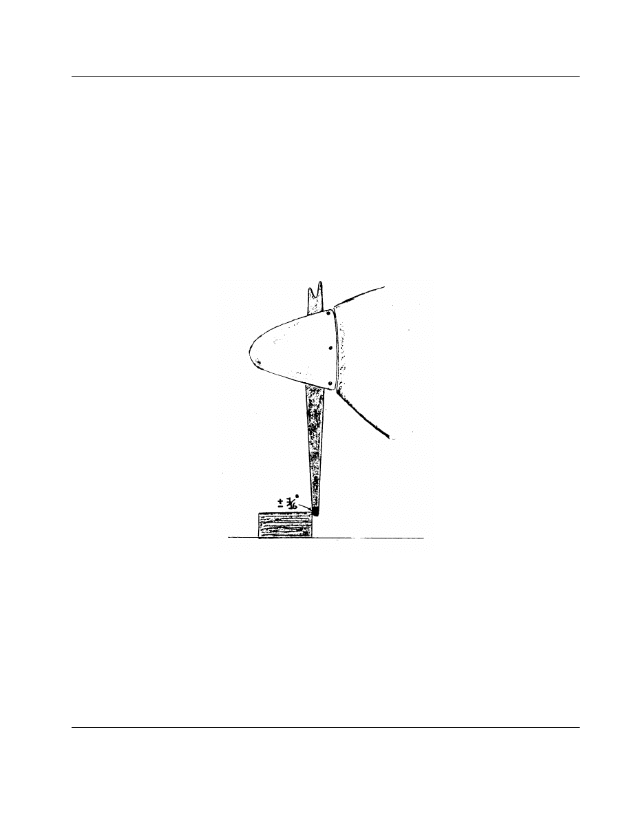
26
5/24/95
AC 90-89A
c.
Never ‘‘PROP’’ an engine on uneven or
wet/snow covered ground.
d.
Always inspect the propeller before and
after a flight.
e.
When working on a propeller, make sure
the ignition is off first.
f.
Always maintain the propeller to manufac-
turer’s instructions.
g.
To avoid nicks and cuts, do not perform
run-ups near gravel/loose stones.
h.
Apply a coat of automotive wax once a
month to protect the finish and keep out moisture.
i.
Assume a propeller is unairworthy if it has
suffered any kind of impact or ground strike.
j.
After any repair or repainting, or if vibra-
tion or roughness is noted, re-balance the propeller.
k.
Propeller blades should be balanced within
1 gram of each other to avoid over stressing the gear
reduction system and propeller shaft.
l.
Check the bolt torque on all newly installed
propellers every hour of operation for the first 10
hours and once every 5 hours thereafter.
m.
After torquing the propeller, track the
blades.
FIGURE 5 - Propeller Tracking
3.
PROPELLER TRACKING CHECK.
a.
Ensuring good powerplant operation first
starts with a properly installed propeller. Each
propeller should be checked for proper tracking
(blades rotating in the same plane of rotation). The
following procedure is simple and takes less than
30 minutes:
(1)
Chock the aircraft so it cannot be
moved. Remove one sparkplug from each cyl-
inder. This will make the propeller easier and safer
to turn.
(2)
Rotate the blade so it is pointing
straight down.
(3)
Place a solid object (e.g., a heavy
wooden block that is at least a couple inches higher
off the ground than the distance between the propel-
ler tip and the ground) next to the propeller tip so
it just touches.

27
5/24/95
AC 90-89A
(4)
Rotate the propeller slowly to see if the
next blade ‘‘tracks’’ through the same point (touches
the block, see figure 2). Each blade should be within
1
⁄
16
’’ from one another.
b.
If the propeller is out of track, it may be
due to one or more propeller blades that are bent,
a bent propeller flange, or propeller mounting bolts
that are over or under torqued. An out-of-track
propeller will cause vibration and stress to the engine
and airframe and may cause premature propeller fail-
ure.
4.
METAL PROPELLER INSPECTION
Per-
haps the two biggest problems affecting the air-
worthiness of metal propellers are corrosion and
nicks on the leading edge.
a.
Identifying Corrosion.
(1)
Surface corrosion can occur on the sur-
face of metal blades due to a chemical or electro-
chemical action. The oxidation product usually
appears on the surface of the metal as a white pow-
der.
(2)
Pitting corrosion causes small cavities
or pits extending into the metal surface. This is an
advanced form of corrosion, appearing as small dark
holes that usually form under decals or blade over-
lays.
(3)
Inter-granular corrosion, rare and dif-
ficult to detect in propellers, is the most dangerous
form of corrosion. It attacks the boundary layers of
the metal, creating patches of lifted metal and white/
gray exfoliation on the surface of the propeller. It
is sometimes found in propellers that had a ground
strike and have been straightened.
(4)
If any of these signs of corrosion are
found, do NOT fly the aircraft. Refer to the manufac-
turer’s maintenance manual for corrosion limits and
repairs or AC 43.4, ‘‘Corrosion Control for Air-
craft,’’ and AC 20-37D, ‘‘Aircraft, Metal Propeller
Maintenance,’’ for additional maintenance informa-
tion and corrective actions.
b.
Nicks and Metal Blades.
(1)
Nicks in the leading and trailing edge
of a metal blade are usually V-shaped. They are
caused by high speed impact between the propeller
and a stone or piece of gravel. Properly trained
individuals can ‘‘dress out’’ the crack if the nick
is not too wide and/or deep. Before each nick is
dressed out, each nick and surrounding area should
be inspected with a 10-power magnifying glass for
cracks. If an area looks suspicious, inspect the area
again using the propeller manufacturer’s approved
dye penetrant or fluorescent penetrant method.
(2)
If the nick is left unattended, the high
propeller operational stresses will be concentrated at
the bottom of the nick’s V and, in time, will generate
a crack. The crack can migrate across the blade until
the blade fails, producing a massive imbalance
between the propeller and the engine, ultimately
causing structural failure. Cracks in metal blades
CANNOT be repaired. A cracked propeller must be
marked unserviceable and discarded.
c.
Warning.
Metal propellers are matched/
tuned to the engine and airframe resonant frequency
by being manufactured with a particular diameter to
minimize vibration. DO NOT SHORTEN METAL
BLADES for any reason unless the manufacturer
specifically permits this major alteration.
5.
PROPELLER INSPECTION.
a.
Wood propellers should be inspected before
and immediately after a flight. Inspect to ensure the
following:
(1)
The drain holes are open on metal
edged blade tips
(2)
The metal/composite leading edge is
secured and serviceable
(3)
The blades, hub, and leading edge have
no scars or bruises
(4)
The mounting bolt torque and safety
wire or cotter pins are secure
(5)
There are no cracks on the propeller
spinner (if applicable), and the safety wire is secure
(6)
There are no small cracks in the protec-
tive coating on the propeller, which are caused by
UV radiation
(7)
The charring around the mating surface
of the prop and the engine flange -- both indications
of a loose propeller
b.
A word about torque: A new, wooden
propeller should have the mounting bolts checked

28
5/24/95
AC 90-89A
for proper torque within the first hour of flight and
every hour for 10 operational hours thereafter.
(1)
After 10 hours, check the bolt torque
every 5 hours thereafter. The mounting bolt torque
also should be checked prior to flight if the aircraft
has been in storage for a long period of time (3 to
6 months).
(2)
If the bolts need to be torqued, it is
suggested all the bolts be loosened for an hour to
allow the wood to relax. ‘‘Finger tighten’’ the bolts
until snug and tighten the attaching bolts in small
increments, moving diagonally across the bolt circle.
It is good practice to check the propeller track (see
chapter 1, section 7) as the bolts are torqued down.
The torqued bolts should be safety wired in pairs.
(3)
If nylon/fiber insert type nuts are used,
they should be changed every time the propeller bolts
are re-torqued. They should never be used with a
bolt with a cotter key hole in the threaded area
because the sharp edges around the hole will cut
the nylon/fiber insert and reduce the fastener’s
effectiveness. All self-locking nuts should have at
least two bolt threads visible pass the nylon/fiber
insert after torquing.
(4)
If any of the following damage is
found, a wood propeller should be removed from
the aircraft and sent back to the manufacturer for
repair. If the propeller cannot be saved, it should
be marked unserviceable.
(i)
Any cracks in the blades or hub
(ii)
Deep cuts across the wood grain
(iii)
Blade track that exceeds
1
⁄
16
’’
limits after attempts to repair
(iv)
Any warpage or obvious defect
(v)
Extreme wear (leading edge
erosion, bolt hole elongation)
(vi)
Any separation between
lamination
NOTE: When parking the aircraft, always
leave the wood propeller in the horizontal
position. This position will allow the wood
to absorb small amounts of moisture evenly
across it’s entire span rather than con-
centrating the moisture (weight) in the low
blade and creating a vibration problem.
6.
COMPOSITE PROPELLERS
INSPECTION.
a.
There are generally two types of composite
propellers: thermo-plastic injection molded propeller
and the carbon/graphite fiber composite propeller.
(1)
The thermo-plastic injection molded
propeller is a low cost, thin bladed propeller used
on engines of 80 horsepower or less. Propeller
inspection is straight forward, by examining the
blades and hub for cracks and nicks. If a crack is
found, do not fly until the propeller is replaced. Small
nicks of
3
⁄
16
of an inch or less can be dressed out
and filled using a two-part epoxy.
(2)
Carbon/graphite composite propellers
are primarily used on engines of 40 horsepower and
more. One should inspect for small hair line cracks
in the gel coat. These spider cracks are usually
caused by vibration generated by a mismatch of the
engine and propeller combination. If a crack in the
base material of the propeller other than the gel coat
is found, do not fly until the manufacturer inspects
the propeller.
(i)
Nicks of
1
⁄
2
inch or less in the
leading or trailing edges of carbon/graphite propel-
lers can be dressed out and filled using a two-part
epoxy. But if the nick has severed the fiberglass rov-
ing (looks like a fiberglass wire bundle) that runs
hub to tip on the leading and trailing edge, do not
fly. The propeller has been severely damaged and
must be sent back to the factory for inspection and
repair.
(ii)
Before making even small repairs
on a composite propeller, check with the manufac-
turer first. Larger nicks must go back to the factory
for inspection and repair.
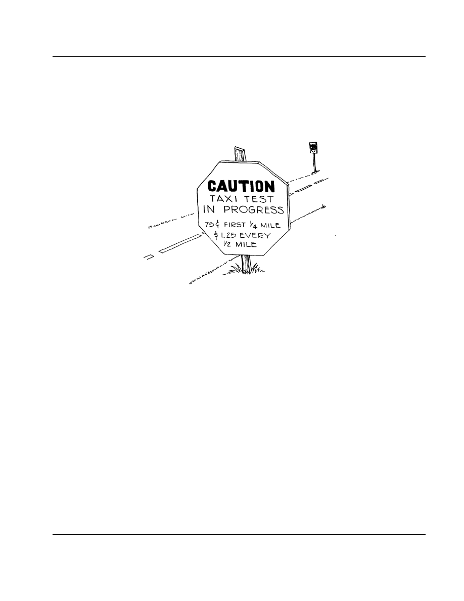
29
5/24/95
AC 90-89A
CHAPTER 2.
TAXI TESTS
SECTION 1.
LOW SPEED TAXI TESTS
‘‘Yelling ’Clear the Prop!’ before you start an aircraft is the first of a series of well planned,
choreographed steps to make you a professional.’’ Jack Crawford, Pilot, Mechanic, Airport Operator
(1994)
1.
OBJECTIVES.
The objectives of the taxi
tests are fourfold:
a.
To ensure that the aircraft ‘‘tracks’’ straight
and there is adequate directional control at 20 percent
below the anticipated take-off speed.
b.
To determine if the aircraft’s engine cooling
and the brake system are adequate.
c.
To predict the flight trim of the aircraft and
its handling characteristics during take off and land-
ings.
d.
To allow the pilot to become proficient with
the handling and braking characteristics of the air-
craft.
NOTE: All taxi tests, low and high speed,
should be made as if it were the first flight.
The pilot should be wearing the proper
clothing, seat belt/shoulder harness and hel-
met and be mentally and physically pre-
pared for the possibility of flight.
2.
TAXI TESTS.
a.
Prior to beginning taxi tests in a conven-
tional (tail dragger) aircraft, the tail should be raised
until the aircraft is in the approximate take-off posi-
tion. The pilot should spend an hour or more in the
cockpit to become accustomed to the aircraft’s take-
off position. This small but important aspect of train-
ing will help the pilot avoid overreacting to an unex-
pected deck angle on the first flight.
NOTE: All taxi tests should always be mon-
itored by a minimum of one other member
of the flight test team, who will watch for
evidence of fire/smoke or other problems not
visible to the pilot.
b.
The taxi tests should begin with a taxi speed
no faster than a man can walk. The pilot should spend
this time getting acquainted with the aircraft’s low
speed handling characteristics by practicing 90, 180,
and 360 degree turns and braking action. The pilot
should also remember that monitoring the oil pres-
sure, oil temperature, cylinder head temperature, and
maintaining them within limits is a critical function
that must not be overlooked.

30
5/24/95
AC 90-89A
NOTE: The builder should be aware that
some aircraft brake manufacturers have
specific brake lining conditioning proce-
dures (break-in) for metallic and non-asbes-
tos organic linings. Proper brake lining
conditioning should be completed before
starting the low and high speed taxi tests.
If not properly conditioned, the brake lining
will wear quickly and give poor braking
action at higher speeds.
c.
The pilot should check the flight
instruments for operation each time the aircraft is
taxied out. The compass should match the magnetic
heading of the runway or taxi way the aircraft is
on. When making a turn (e.g., right hand turn), the
turn coordinator/turn and bank should indicate a right
hand turn but the ball should skid to the left. The
vertical speed indicator should read zero and the
artificial horizon should indicate level.
d.
After each taxi run, inspect the aircraft for
oil and brake fluid leaks. No leak should be consid-
ered a minor problem. Every leak must be repaired
and the system serviced prior to the next taxi test.
SECTION 2.
HIGH SPEED TAXI TESTS
‘‘First get use to the fact that you are now 30 feet wide and you steer with your feet.’’ Wayne Nutsch
1.
OBJECTIVE.
To determine the aircraft’s
high speed handling and braking parameters.
a.
Propeller rotation will determine which rud-
der pedal is pressed to compensate for the asymmet-
rical thrust of the propeller blades. For example,
when viewed from the cockpit, a Volkswagen auto-
motive engine mounted in a tractor configuration will
rotate the propeller counter-clockwise. In this case,
the pilot must use the left rudder pedal for high speed
taxi and take-off.
b.
As with every part of the flight testing pro-
gram, the high speed taxi tests should follow the
FLIGHT TEST PLAN. Start slowly and do not
progress to the next step until everyone is thoroughly
satisfied with the aircraft and his/her own perform-
ance.
c.
Each taxi run should be 5 mph faster than
the last run until the aircraft is within 80 percent
of the predicted stall speed. Prior to reaching the
predicted stall speed, the pilot should test aileron
effectiveness by attempting to rock the wings
slightly. As taxi speeds increase, the rudder becomes
more responsive and directional control will
improve.
(1)
In a nose gear aircraft, the pilot should
be able to raise the nose of the aircraft to a take
off attitude at 80 percent of the stall speed. If the
nose cannot be raised at this speed, the weight and
balance and CG range should be rechecked. Most
likely there is a forward CG problem or the main
gear is too far aft.
(2)
In a tail wheel aircraft at 80 percent
of stall speed, the pilot should be able to lift the
tail and assume a take-off position. Again, if the tail
cannot be raised, recheck the weight and balance and
CG range. Most likely there is a rearward CG prob-
lem or the main gear is too far forward.
CAUTION: Heavy braking action at
high speeds in tail wheel aircraft may
cause directional problems (ground
loops) or nose overs.
c.
If runway conditions permit, duplicate each
taxi test with the flaps in the take-off and landing
configuration. Record the flap effects on directional
control and insert the information in the draft copy
of the aircraft’s flight manual.
d.
Determine the approximate point on the
runway where lift-off will occur and mark it with
a green flag if no other existing reference is available.
e.
Determine how much runway the pilot will
need if it becomes necessary to abort the take-off.
This is usually accomplished by accelerating to 80
percent of lift off speed, bringing the engine back
to idle, and applying heavy braking action to bring
the aircraft to a full stop. After each take-off/abort
test, the brakes must be allowed to COOL DOWN.
The lining must be examined carefully and replaced
if necessary.
f.
After determining the distance required to
come to a full stop after aborting, add 30 percent
to the distance. Measure that distance from the
OPPOSITE end of the active runway which will be

31
5/24/95
AC 90-89A
used. If no existing reference is available, mark it
with a red flag. The taxi tests are completed when
the test pilot is satisfied with both the aircraft’s and
his/her individual performance. Prior to the first
flight, the aircraft should be thoroughly inspected
with special attention given to the landing gear, brake
system, engine, and propeller.
g.
During this inspection all discrepancies
must be fixed. Examine the screens/filters for metal,
flush the fuel system, and clean all the screens/filters.
Perform a leak check on the engine and the fuel
system by running-up the engine.
h.
Notes.
(1)
The first high speed taxi tests should
be made in a no wind or a light head wind condition.
The pilot should ensure that the tests will not inter-
fere with the normal airport operations or create a
safety hazard for other aircraft.
(2)
If the aircraft’s engine is not a U.S. type
certificated engine, the pilot should determine which
way the propeller rotates.
(3)
Pilots of tail wheel aircraft must always
be aware that ground loops are possible at any speed.
This is true especially if the main landing gear is
located too far forward of the aircraft’s CG.

32
5/24/95
AC 90-89A
THIS PAGE INTENTIONALLY LEFT BLANK
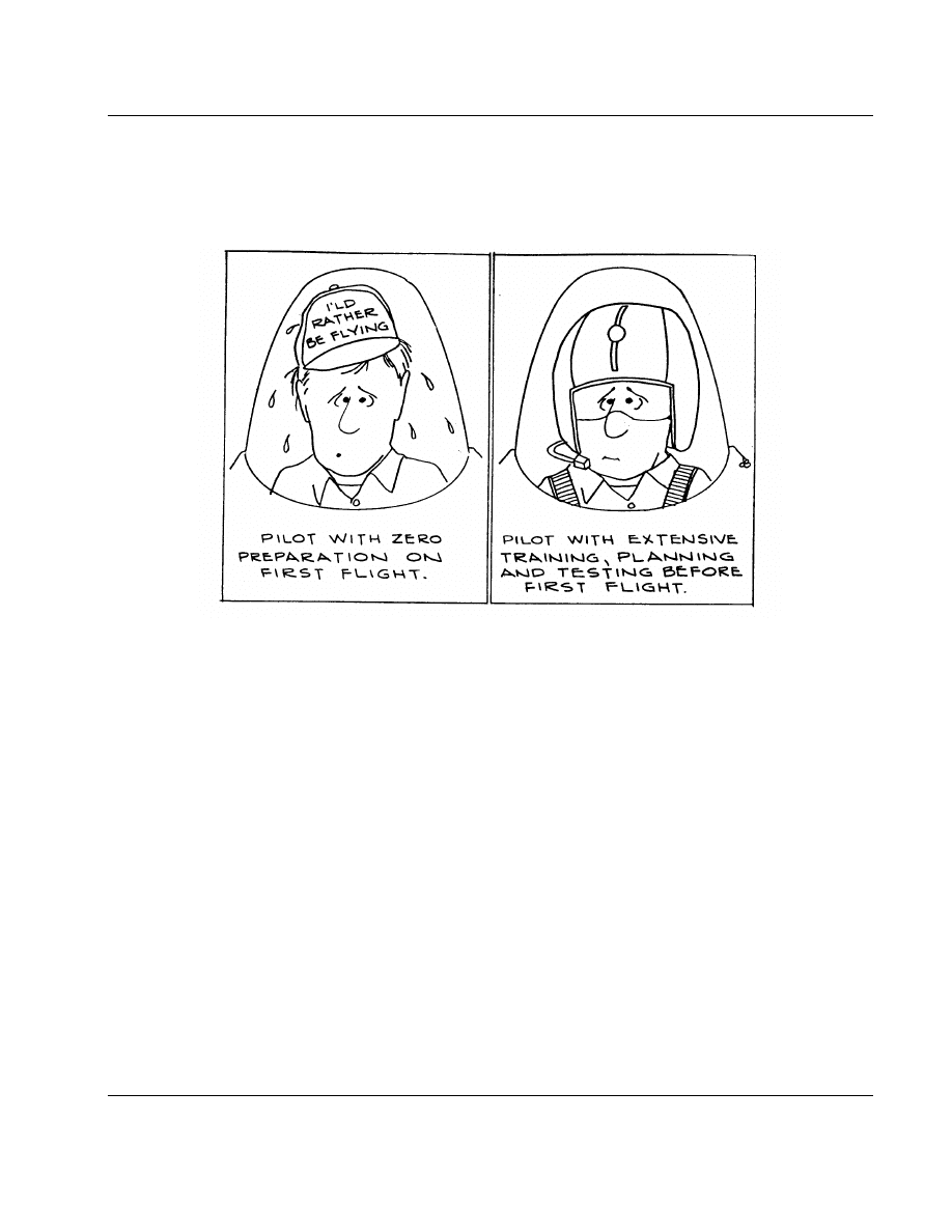
33
5/24/95
AC 90-89A
CHAPTER 3.
THE FIRST FLIGHT
‘‘It is critically important that a test pilot never succumb to the temptation to do too much too soon, for
that path leads but to the grave.’’ Richard Hallion (1987)
SECTION 1.
GENERAL
1.
OBJECTIVE.
To take every precaution to
ensure that the first test flight is an ‘‘uneventful’’
one.
2.
GENERAL.
a.
The first flight is an important event for
an amateur-builder. As important as it is, it should
not be turned into a social occasion. This puts enor-
mous peer pressure on the pilot to fly an aircraft
that may not be airworthy or to conduct the flight
in inclement weather.
b.
A ‘‘professional’’ will avoid this trap by fol-
lowing the FLIGHT TEST PLAN and inviting only
those members of the crew needed to perform
specialized tasks when testing the aircraft.
c.
A safe and uneventful first flight begins
with verifying all emergency equipment and person-
nel are standing by, radio communications are func-
tional, members of the crew are briefed, weather is
ideal, and the aircraft is airworthy. The pilot must
be rested and physically and mentally ready for the
first flight and every flight thereafter. The pilot also
should review any new data developed for the air-
craft’s flight manual.
d.
The first flight should be flown a thousand
times: the first 500 on paper, the next 499 flights
in the test pilot’s mind -- and once in actuality. The
first flight test should be so well-rehearsed by the
test pilot and ground crew that the first flight is a
non-event.

34
5/24/95
AC 90-89A
31.
RECOMMENDATIONS.
a.
The best time to test fly an aircraft is usu-
ally in the early morning when the winds are calm,
and the pilot is well rested.
b.
In addition to a pilot’s knee board, a small
portable tape recorder or video camera properly
mounted to the aircraft is an excellent way to record
data.
c.
Good communication with the ground is
essential for data exchange and safety.
4.
FIRST FLIGHT INSPECTION.
a.
Prior to the first flight, the aircraft should
be given a good pre-flight inspection by the pilot
and at least one other experienced individual. A thor-
ough aircraft pre-flight inspection should ensure that:
(1)
The fuel on board is four times the
amount of usable, clean, and proper octane fuel than
is needed for the first flight. If a 2 cycle engine is
used, check that the oil to fuel mix ratio is correct.
(2)
A current weight and balance check is
completed. The aircraft’s CG should be in the for-
ward half of the safe CG range. This will reduce
the possibility of instability during approach to a stall
and enhance recovery from one.
(3)
Check oil, brake fluid, and hydraulic
system for the correct fluid and quantity.
(4)
Canopy or cabin door latches lock
securely and will not vibrate loose in flight.
(5)
Fuel valve is in the proper position and
vent lines are open.
(6)
Trim tabs set in the take-off position.
(7)
Altimeter set to the field elevation and
cross-checked with the local altimeter setting.
(8)
The complete control system has been
given a functional check.
(9)
Check of all ground and air commu-
nications frequencies for proper operation.
(10)
Engine cowling and airframe inspec-
tion plates/fairings secured.
(11)
The airspeed indicator marked with
sticky tape at the ‘‘predicted’’ BEST CLIMB speed,
BEST GLIDE speed and MANEUVERING speed.
If these speeds are not available from prototype flight
test data, the following are conservative guidelines
to initially determine the referenced speeds:
(i)
BEST ANGLE OF CLIMB (V
x
)
= 1.5 times the aircraft’s predicted lift-off speed.
(ii)
BEST GLIDE SPEED = 1.5 times
the aircraft’s predicted lift-off speed.
(iii)
MANEUVERING SPEED (V
a
) =
2 times the aircraft’s predicted stall speed.
(iv)
For applicable aircraft, it is advis-
able to put the maximum landing gear operating
speed (V
lo
) and maximum flap extension speed (V
fe
)
on a piece of masking tape and attach it to the
instrument panel for reference.
SECTION 2.
THE ROLE OF THE CHASE PLANE
1.
OBJECTIVE.
To determine whether a chase
plane should be used during the FLIGHT TEST
PHASE.
2.
GENERAL.
To use or not to use a chase plane
should be a ‘‘test pilot’s’’ decision. If a chase plane
is used, it must serve a specific set of functions
identified in the FLIGHT TEST PLAN. Its overall
purpose is to contribute to gathering flight test data
and flight safety. The chase plane should not serve
as a distraction to the test pilot or only as a platform
for a home camcorder/camera.
a.
The primary functions of the chase plane
are as follows:
(1)
To watch the parts/systems of the test
aircraft not visible to the test pilot and report any
problems
(2)
To assist the test pilot in following the
FLIGHT TEST PLAN
(3)
Watch for and inform the test pilot of
other aircraft
(4)
Assist in an emergency situation

35
5/24/95
AC 90-89A
b.
If a chase plane is used, the following
suggestions are offered:
(1)
A single chase plane should be used
on the first two flights and the first time the amateur-
built aircraft’s landing gear is retracted. The chase
plane pilot should be experienced in formation flying
and thoroughly briefed prior to each flight.
(2)
There should be at least two pilots on
board the chase plane. One pilot’s sole duty is to
fly the aircraft and maintain a safe distance from
the amateur-built aircraft. The other pilot serves as
an observer whose duties include checking for other
traffic, the condition of the test aircraft, and commu-
nicating with the pilot on the frequency assigned by
air traffic control (ATC) (e.g., 122.75 megahertz
[MHz]).
(3)
A good chase plane position is about
100/200 feet off the right side and slightly behind
and below the test aircraft. Avoid flying directly
behind the test aircraft. It is not uncommon that on
first flights, fuel and oil leaks develop and small
hardware and fasteners could vibrate off the aircraft.
NOTE: Pilots of Both Aircraft Must Keep
Each Other Informed of Their Intended
Action or Maneuver Prior to Execution.
c.
In an emergency situation:
(1)
If the test aircraft’s radio fails, the
chase plane should serve as an airborne communica-
tion relay with the tower/ATC facility for the test
aircraft.
(2)
For other emergency situations, the
chase plane should provide the test pilot with
information or assistance as required. If necessary,
the chase plane can guide the test pilot to a safe
landing at the airport or an emergency field. If the
test aircraft goes down off the airport, the chase plane
can serve as an overhead spotter that can direct emer-
gency personnel to the test aircraft location.
SECTION 3.
EMERGENCY PROCEDURES
‘‘At the worst possible time, the worst possible thing will happen.’’ Murphy’s Law
1.
OBJECTIVE.
To develop a complete set of
in-flight emergency procedures for the aircraft that
are designed to make unmanageable situations
manageable.
2.
GENERAL.
The FLIGHT TEST PLAN
should have a special section on emergency proce-
dures. The responses to each emergency should have
been developed based on the aircraft’s predicted
flight characteristics, airport location, surrounding
terrain, and nearby emergency fields.
a.
The following is a partial list of possible
emergencies that may arise during the flight test
phase and includes suggested responses:
(1)
PROBLEM:
Engine failure on take-
off.
RESPONSE:
Fly the aircraft! Estab-
lish best glide speed. If time permits, try to restart
engine. If altitude is below 800 feet and the engine
will not start, land straight ahead or 20 degrees on
either side of the runway centerline. This is sug-
gested because in most cases the aircraft will run
out of altitude or airspeed as the pilot attempts a
180 degree turn back to the airport. Declare an
emergency and shut off the master switch, fuel,
and magnetos to reduce the possibility of fire on
landing. Above 800 feet, the chances of making a
180 degree turn to land downwind on the runway
or another emergency field nearby are directly
proportional to the wind velocity and the numbers
of practice emergency landings the pilots has made
in similar make and model aircraft.
(2)
PROBLEM:
Engine vibration in-
creases with rpm.
RESPONSE:
Fly the aircraft!
Reduce power or increase power to minimize the
effect of vibration, but maintain safe airspeed and
altitude. Run through the emergency checklist and
land as soon as possible.
(3)
PROBLEM:
Smoke in the cockpit.
RESPONSE 1:
Fly the aircraft! If
the smoke smells like burnt plastic wire installation,
shut off the master switch. Put on smoke goggles,

36
5/24/95
AC 90-89A
open the fresh air vents to clear the cockpit, and
land as soon as possible.
RESPONSE 2:
Fly the aircraft! If
the smoke is bluish/grey and has an acrid odor like
burning oil, shut off the fresh air/hot air vents and
put on the smoke goggles. Monitor oil pressure and
temperature. Be prepared to shut the engine down
and land as soon as possible.
(4)
PROBLEM:
Engine fire.
RESPONSE:
Fly the aircraft! Shut
off the fuel selector, mixture master switch, and
magnetos. Land as soon as possible.
(5)
PROBLEM:
Out of rig condition.
RESPONSE:
Fly the aircraft! Try to
use the appropriate trim to offset adverse control
pressures. Keep the airspeed high enough to maintain
altitude. Make small control inputs, reduce power
slowly to avoid controllability problems, and land
as soon as practical.
(6)
PROBLEM:
Cabin door opening in
flight.
RESPONSE:
Fly the aircraft! A par-
tially open door usually affects the airflow over the
tail causing reduced control response and vibration.
Reduce speed, maintain level flight, and yaw/slip the
aircraft left or right to reduce vibration. Open the
side vent window to reduce air pressure resistance
in the cabin and attempt to shut the door. Sometimes
putting the aircraft in a skid will assist in closing
a partially open door.
b.
Other possible emergencies to plan for
include:
(1)
Canopy opening unexpectedly
(2)
Loss of communications
(3)
Throttle stuck in one position
(4)
Oil on the windshield
(5)
Propeller throws a blade
(6)
Fire in the cockpit
SECTION 4.
FIRST FLIGHT
‘‘Always leave yourself a way out.’’ Chuck Yeager
1.
OBJECTIVES.
The two objectives of the first
flight are to determine engine reliability and flight
control characteristics.
a.
After completing the pre-flight inspection,
the test pilot should ensure that the seat/shoulder har-
ness is properly fitted and allows easy access to all
the cockpit controls (verified by a crew member).
Following the FLIGHT TEST PLAN and using
the starting checklist, warm up the engine until the
engine instruments indicate normal operating
temperatures and pressures.
b.
A complete check of each aircraft system
should be performed (e.g., carb heat, magnetos, static
rpm, and brakes).
c.
If the airport does not have a tower/unicom
available, the pilot should transmit over 122.9 MHz
the following message: ‘‘This is experimental air-
craft N
lll on the first test flight, departing run-
way
lll at lll airport, and will remain in
the local area for the next hour.’’ Transmit the air-
craft N number, location, and intentions every ten
minutes.
d.
If the airport is equipped with a tower,
notify them that an experimental aircraft is on its
first test flight and requests take-off instructions.
e.
After being given clearance to take-off,
clear the area, line up on the runway centerline,
release the brakes, and slowly add power to provide
‘‘Thinking Time.’’ When the throttle is fully
advanced, glance at the an oil pressure gauge and
tachometer to confirm they are in the green and
indicating take-off rpm. A type certificated engine
of a 100 horsepower will produce between 2100 to
2300 rpm on the take-off roll, depending on the type
of propeller installed. If either oil pressure or
tachometer is reading low, abort the takeoff!
f.
If there is any unusual vibration, rpm
exceeding the red line, or engine hesitation, abort
the takeoff!

37
5/24/95
AC 90-89A
g.
If in a tail wheel aircraft, keep the tail on
the runway until the rudder is effective. This usually
happens at approximately 35 mph on most aircraft.
h.
As the aircraft accelerates and approaches
the predicted/manufacturer’s lift off speed/point
(green flag), gently ease back on the stick. The first
take-off should be a gentle and well-controlled
maneuver with the aircraft doing all the work.
i.
If the aircraft does not want to rotate or
unusual stick forces are experienced, abort the
takeoff!
j.
If the aircraft has retractable gear, do not
raise the gear on the first two to three flights until
the aircraft’s stability/control responses have been
explored a little further.
k.
It is recommended that after establishing
a safe climb angle. the pilot DOES NOT throttle
back, switch tanks, or make large inputs into the
flight controls for the first 1,000 feet. At the
preselected altitude, reduce power slowly to avoid
a pitch up or pitch down that might be associated
with rapid power reductions.
NOTE: Check if there is any additional stick
or rudder input pressure during the climb.
Try reducing any abnormal stick pressures
with trim. Each control input should be
small and slow.
l.
If any unusual engine vibrations, rapid oil
pressure fluctuation, oil and cylinder head tempera-
tures approaching red line, or decreasing fuel pres-
sure is experienced, refer to the emergency check
list and land as soon as possible.
SECTION 5.
FIRST FLIGHT PROCEDURES
‘‘In my opinion, about 90 percent of your risk in a total program comes with a first flight. There is no
nice in-between milestone. You have to bite it off in one chunk.’’ Deke Slayton
1.
OBJECTIVE.
To perform a series of tests to
develop data that will ensure a safe landing.
a.
The First Test Flight.
(1)
After take-off, climb to 3,000 feet
above ground level (AGL) and level off. Reduce
power slowly. Complete the cruise checklist items.
Following the FLIGHT TEST PLAN, circle the air-
port or emergency field as the engine performance
is being monitored.
(2)
Limit the cruise speed to no more than
1.5 the predicted stall speed of the aircraft. This will
reduce the chances of flutter. If the engine appears
to be operating smoothly, try testing the flight con-
trols.
(3)
With the airspeed being monitored,
each control input should be gentle and small. Start
with the rudder first. Yaw the nose of the aircraft
5 degrees left and right. Note the response. Raise
the aircraft’s nose 3 degrees up, note the response.
After the aircraft is stabilized, level off and try three
degrees nose down, trim, and note the response. Try
a gentle bank of no more than 5 degrees to the left,
then one to the right. If the aircraft is stable and
is operating smoothly, try a few 90 degree clearing
turns, followed by two 360 degree turns: one to the
left and one to the right at a bank angle of 10 degrees.
(4)
If the aircraft is responding to the pre-
scribed specifications, increase the bank angle in
succeeding turns to 20 degrees. If no problems are
encountered, climb to 5,000 feet AGL (using the
climb checklist and monitoring engine gauges), level
off, fly an imaginary landing pattern, and test the
flaps. Do not forget to announce every 5 to 10 min-
utes the aircraft’s location, altitude, and intentions.
Practice approach to landing by descending to 4,000
feet AGL first, then to 3,000 feet. Remember, use
the descent checklist.
(5)
During these maneuvers, control pres-
sures should increase in proportion to control deflec-
tion. If control pressure remains the same as control
deflection increases or if stick forces become lighter
as control deflection increases, the aircraft may have
a stability problem. Avoid large control movements
and land as soon as possible.
(6)
Remember to keep informing the
tower/UNICOM/chase plane of what is happening.
For 10 minutes of anticipated flight time, plan a brief
rest period for the pilot. Fly straight and level, mon-
itor the gauges, and enjoy the experience.

38
5/24/95
AC 90-89A
(7)
At low cruise power setting, straight
and level, observe how the aircraft trims out. Do
the ‘‘fixed’’ trim tabs on the rudder and aileron need
adjustment? Are the adjustable aileron and elevator
trim control effective? Is the control stick/yoke
slightly forward of the mid-position in straight and
level flight?
(8)
Climb slowly back up to 5,000 feet.
Two questions must be answered before landing:
(i)
Is the aircraft controllable at low
speeds?
(ii)
What is the approximate stall
speed?
(9)
These questions can be answered with
an approach to a stall maneuver. Do NOT perform
a FULL STALL check at this time!
(10)
The necessity for an approach to a stall
check is because it will help establish a preliminary
stall speed (V
si
) in mph/knots so the approach speed
for landing can be calculated. Also, the pilot will
have knowledge of the aircraft’s handling character-
istics at low speed.
b.
Suggested Procedure.
(1)
Level off at altitude; make two clearing
turns; stabilize airspeed, heading, and altitude; apply
carb heat; set the flaps in the landing configuration
and reduce power slowly to 900 rpm. TRIM. If, as
is not uncommon on first flights, the aircraft cannot
be trimmed properly, the pilot can still proceed with
the check as long as the stick forces are not unusually
heavy.
(2)
With the aircraft airspeed approxi-
mately 1.4 mph/knots times (X) the predicted stall
speed, raise the nose slowly. It is desirable for the
aircraft to start decelerating slowly, about
1
⁄
2
mph/
knot a second. A 30 mph/knot deceleration at
1
⁄
2
mph/knot per second will take only a minute.
(3)
As the aircraft slows down, note all the
things that happen as the speed bleeds off. Observe
the changing nose attitude and how the stick force
changes. Keep the turn coordinator or turn and bank
‘‘ball’’ in the middle.
(4)
Note how much rudder it takes to keep
the ball centered. Every few seconds make very
small control inputs to check that the aircraft is
operating in the prescribed manner. If the aircraft
does not respond to small control inputs -- and it
should not be expected to respond as quickly as it
did at higher speeds -- make the inputs a little bit
larger. Increase the amount of input progressively.
Do not simultaneously put in all three control inputs.
Give particular attention to the response to nose-
down elevator inputs, which is necessary for recov-
ery.
(5)
Notice any changes in flight character-
istics and the speeds at which they take place. Be
especially alert for the onset of pre-stall buffet. Is
the buffet felt through the stick? Through the air-
frame? Though the seat of the pants? Does the nose
of the airplane want to rise or drop on its own? How
strong is the buffet? Is it continuous? Would it get
the pilot’s attention if they were concentrating on
something else?
NOTE: On some high performance aircraft
and aircraft with unusual wing designs, a
pre-stall buffet may not exist and the stall
may be abrupt and violent with a large
degree of wing drop.
(6)
Keep making small control inputs at
intervals to check the aircraft’s responses. At
approximately 5 mph/knots before the predicted stall
speed, or at the first sign of a pre-stall buffet, note
the airspeed and stop the test. Recover and write
down the pre-stall indicated airspeed. This airspeed
should be the reference stall speed for the first land-
ing.
(7)
The pre-stall recovery response should
be a smooth and quick forward stick movement. This
response should be enough to reduce the angle of
attack to the point where the airplane is flying nor-
mally again.
(8)
A wing drop would be unexpected so
early in the approach to a stall, but if it becomes
necessary to raise a low wing do it with rudder, NOT
OPPOSITE AILERON. Use of ailerons at lower
speed would increase the chances for a stall or a
sudden departure from controlled flight.
(9)
There is no need to gain more airspeed
than the extra few mph/knots to fly out of a pre-
stall condition. After returning to straight and level
flight and using the information learned, the pilot
can practice a few more recoveries from a pre-stall
condition. Remember the aircraft will constantly be

39
5/24/95
AC 90-89A
loosing altitude so it is necessary to climb back up
to 5,000 feet AGL to continue further flight testing.
Do not get so involved that the overall objective of
the first flight is lost -- which is getting the pilot
and aircraft safely back on the ground.
(10)
The FLIGHT TEST PLAN for the first
flight should call for a maximum of 1 hour of actual
flight time. This is to reduce pilot fatigue and the
possibility of an engine failure or airframe malfunc-
tion occurring due to vibration or construction errors.
NOTE: The pilot may elect to make several
practice approaches to landing at altitude or
low approaches to the active runway to get
a solid understanding of the lower airspeeds,
aircraft attitude, and overall feel of the air-
craft in the landing configuration. Before
each low approach at the airport, the tower/
UNICOM/chase plane should be advised of
the pilot’s intentions. Avoid other traffic in
the pattern, and use the landing checklist.
(11)
When the pilot has completed all the
tests called for by the FLIGHT TEST PLAN, notify
the tower/UNICOM/chase plane of the intent to land.
Complete the landing checklist before entering
downwind. Keep all turns less than 20 degrees of
bank, but do not cross-control by using the rudder
to move the nose. This will increase the bank angle,
which most pilots will correct by using opposite aile-
ron. If allowed to continue, and with back pressure
on the stick, this will result in a cross-control stall
and a roll to a near vertical bank attitude at the begin-
ning of a spin with no altitude left for recovery.
(12)
On final approach, the aircraft speed
should be no less than 1.3 but no more than 1.4
times the recorded ‘‘first flight’’ pre-stall speed.
Homebuilt biplanes (high drag) should use an
approach speed of 1.5 x stall speed on landings.
(13)
Landings, especially the first one in an
amateur-built or kit plane, are always exciting. Pro-
ceed slowly and do not over control. If the landing
conditions are not ideal, be prepared to go around.
(14)
The actual touchdown should take
place within the first 1,000 feet with braking action
being applied before the red (abort) flag marker on
the runway.
(15)
After taxiing in, secure the aircraft,
debrief the flight with members of the team, then
together perform a careful post-flight inspection of
the aircraft.
NOTE: Remember to allow enough time to
absorb what has been learned about the air-
craft’s performance and the pilot’s and
ground crew’s responses to it.

40
5/24/95
AC 90-89A
THIS PAGE INTENTIONALLY LEFT BLANK

41
5/24/95
AC 90-89A
CHAPTER 4.
THE FIRST 10 HOURS
‘‘One can get a proper insight into the practice of flying only by actual flying experiments.’’
Otto Lilienthal (1896)
SECTION 1.
THE SECOND FLIGHT
1.
OBJECTIVE.
To re-affirm the first flight
findings.
a.
Before the second flight, the pilot should
ensure that all discrepancies noted on the first flight
are corrected. It is probable that more ground run-
ups, rigging adjustments, or taxi tests will be
required. Under no circumstances should a pilot take-
off in an aircraft with known airworthiness problems.
The Law of Aerodynamics does not often forgive
these types of mistakes.
b.
The pre-flight inspection should be the
same as performed for the first flight, including
draining the oil and inspecting the oil and fuel
screens for contamination.
c.
The second flight, again lasting approxi-
mately an hour, should be a carbon copy of the first
one, with the exception that all first flight discrep-
ancies are corrected. If problems are not corrected,
all further flight testing should be canceled until solu-
tions are found.
SECTION 2.
THE THIRD FLIGHT
‘‘Plan the flight, fly the Plan.’’ Sign on the wall at the Naval Test Pilot School, Patuxent River, MD
1.
OBJECTIVE.
To validate the engine reliabil-
ity.
2.
GENERAL.
The third flight should con-
centrate on engine performance. Do not forget to
record the engine’s response to any application of
carb heart, leaning of the fuel mixture, changes to
airspeed, and its response to switching fuel tanks.
a.
Engine oil pressure, oil temperature, fuel
pressure, and cylinder head temperatures should be
monitored and recorded from 55 percent through 75
percent rpm. At the higher rpm, be sure not to exceed
80 percent of the maximum cruise speed. This is
to avoid the possibility of encountering a flutter
condition. Do not forget to record the engine
responses to any applications of carb heat, leaning
the fuel mixture, changes to the power settings (RPM
and Manifold pressure), changes to airspeed, and its
response to switching fuel tanks.
b.
Resist the temptation to explore the more
exciting dimensions of flight. Stick to the FLIGHT
TEST PLAN and perform a conscientious evaluation
of the engine. After landing, review the data with
the crew members. Make adjustments as needed, per-
form another post-flight inspection of the aircraft,
and record oil and fuel consumption.
c.
After three hours of flight testing, the pilot
should be able to make the initial determination that
the aircraft is stable and engine is reliable in cruise
configuration.
SECTION 3.
HOURS 4 THROUGH 10
‘‘Keep your brain a couple steps ahead of the airplane.’’ Neil Armstrong
1.
OBJECTIVE.
To build on the data estab-
lished by the first three hours and start expanding
on the flight test envelope in a thorough and cautious
manner. This operational data will be added to the
aircraft’s flight manual.
2.
GENERAL.
These next seven 1-hour test seg-
ments should confirm the results of the first 3 hours
and explore the following areas:
a.
Gear retraction (if applicable)

42
5/24/95
AC 90-89A
b.
Climbs and descents to preselected altitudes.
(monitor engine performance)
c.
Airspeed indicator in-flight accuracy check
NOTE: After each test flight, ALL
DISCREPANCIES must be cleared before
the next flight. The aircraft also must be
THOROUGHLY INSPECTED prior to the
next flight.
NOTE: It is recommended that all flight test
maneuvers be preceded with two 90 degree
clearing turns to ensure that the flight test
area is free of other aircraft.
3.
GEAR RETRACTION.
a.
Before the gear is retracted in flight for the
first time, it is advisable to put the aircraft up on
jacks and perform several gear retraction tests,
including the emergency gear extension test. These
tests will determine if, in the last three hours of flight
testing, any structural deformation or systems mal-
functions have occurred. In addition to the gear
retraction test, the pilot/chase pilot/ground crew
should use this time to review the aircraft’s kit/
designer instructions and emergency checklist proce-
dures for malfunctioning gear and plan accordingly.
If at any time the aircraft has suffered a hard landing
or side loading on the gear during flight testing, the
aircraft and its gear should be tested for operation
and condition on the ground.
b.
The first gear retraction test should be con-
ducted with the aircraft flying straight and level at
or above 5,000 feet AGL, over an airport or emer-
gency field. The airspeed must be well under the
maximum landing gear retraction airspeed. When the
gear is being retracted, note if there is any tendency
for the aircraft to yaw, pitch, or roll. Record what
changes to the aircraft’s trim are required to maintain
straight and level flight. If there are no adverse flight
reactions or system malfunctions, cycle the gear sev-
eral times. When satisfied with the straight and level
gear retraction test, try an emergency gear extension
but only if this is practical.
c.
With the gear extended, slow the aircraft
to 1.3 times the pre-determined stall speed, stabilize,
lower the flaps to the take-off position, trim, and
maintain straight and level flight.
d.
Simulate a normal takeoff by increasing
rpm to full power. Raise the nose 3 degrees, trim,
and then retract the gear. Observe the following: air-
craft reaction, such as pitch or roll; length of time
for gear to retract; trim requirements;, and the time
necessary to establish a 1,000-foot climb before
leveling off.
e.
Practice a simulated takeoff several times
to ensure that the aircraft’s response is predictable
and the gear retraction system is mechanically reli-
able.
4.
CLIMBS AND DESCENTS.
The purpose of
these tests is to monitor engine performance and
reliability. The pilot should start the test only after
the aircraft has been flying straight and level for a
minimum of 10 minutes to stabilize engine oil pres-
sure and temperatures.
a.
Engine oil pressure and temperatures must
be kept within the manufacturer’s limits at all times
during these tests. High summer temperatures may
place restrictions on the flight test program because
both oil and cylinder head temperatures will increase
1 degree for each 1 degree increase in outside
temperature.
(1)
Climbs.
Start the first climb at a 15
degree climb angle, full power, at a predetermined
designated altitude (e.g., 1,000 feet). Maintain the
climb angle for 1 minute. Record the engine tempera-
tures and pressures. Reduce power, stabilize the
engine temperature, and repeat the test. For the sec-
ond climb test, the Flight Test Plan should call for
increasing the climb time -- record the results. When
satisfied that an engine cooling problem does not
exist at this climb angle, repeat the tests using steeper
climb angles until the pilot has reached 15 degrees
or encountered an engine manufacturer’s limit or a
5-minute climb period at full throttle has been
reached.
(2)
Descents.
Should begin above 5,000
feet AGL with both the engine temperatures and
pressures stabilized.
(i)
The test pilot should use carb
heat and clear the airspace below him before
starting the descent. The first descent should be
at a shallow angle, at low rpm and last for 30 sec-
onds, not exceeding 1.5 times the estimated stall
speed of the aircraft. During long, low power
descents, the pilot must be on the alert for too rapid
cooling of the engine usually identified by a signifi-

43
5/24/95
AC 90-89A
cant drop in oil and CHT temperature. If a noticeable
drop occurs, increase the engine rpm and reduce the
angle of descent. If not corrected, the repeated rapid
cooling of the engine may cause thermal shock to
the engine cylinders and eventually cause cylinder
head cracking or seizure.
(ii)
Conduct each test as before, but
increase the time by 30 seconds until limited by the
engine manufacturer’s restrictions or 5-minute
descents are reached. Record temperatures, pres-
sures, altitudes, and airspeeds data for climbs and
descents for addition into the aircraft’s flight manual.
5.
AIRSPEED IN-FLIGHT ACCURACY
CHECK.
The following procedure for airspeed
calibration is offered for evaluation:
a.
A measured course should be chosen with
readily identifiable landmarks at each end. The land-
marks should be a known distance apart, and the
length of course should be at least 1 to 2 miles long.
b.
The pilot must fly a precision course
maintaining a constant altitude (e.g., 1,000 feet), con-
stant airspeed, constant magnetic heading, and con-
stant engine rpm. The pilot must record the tempera-
ture, altitude, indicated airspeed and the time over
each landmark for both directions. The average of
these speeds is the ground speed of the aircraft. An
E6B computer will convert the temperature, altitude,
and ground speed into True Indicated Airspeed for
the tests.
NOTE: The difference between the E6B
computer readings and the aircraft’s ground
speed readings is the error in the instrument
and the error caused by the installation of
the system in the aircraft.
c.
The airspeed calibrations runs should be
made several times in opposite headings for each
of the selected airspeeds the pilot wants to check.
Such accuracy test runs should start at the lowest
safe airspeed and work up to cruise speed using 10
mph/knot increments.
d.
Most errors will be found at the low end
of the speed range due to the angle of the pitot mast
to the relative wind and/or the location of the static
ports. Recently, amateur-builders have been using
Global Positioning Satellite (GPS) hand held receiv-
ers to check airspeed accuracy.
NOTE: Flight testing of all amateur-built
aircraft is restricted to a flight test area. If
a pilot must run additional tests on the air-
craft that require more airspace, he should
notify the FAA District Office that issued
the aircraft’s operating limitations and
request a change to those limitations. If a
pilot is found to be operating an EXPERI-
MENTAL AIRCRAFT in violation of the
aircraft’s Operating Limitations, the FAA
may take certificate action.
e.
If the aircraft has retractable gear or flaps,
test the accuracy of the airspeed indicator with the
gear/flaps up and down.
f.
Record all the data in order to prepare an
airspeed calibration table for the flight manual.

44
5/24/95
AC 90-89A
THIS PAGE INTENTIONALLY LEFT BLANK

45
5/24/95
AC 90-89A
CHAPTER 5.
EXPANDING THE ENVELOPE
‘‘Checklist! Checklist!! Checklist!!!’’ Jim Byers, Flight Instructor/Examiner
SECTION 1.
GENERAL
1.
OBJECTIVE.
To move from a known flight
environment to an unknown flight environment using
a series of planned and carefully executed steps.
a.
Before beginning the next series of test
flights, it is highly recommended that the aircraft
undergo a ‘‘Condition Annual’’ inspection as identi-
fied in the FAA Operation Limitation the amateur-
builder received with the special airworthiness cer-
tificate. It is strongly recommended that the builder
and/or pilot TAKE THE TIME to inspect the aircraft
because within the previous 10 hours, the aircraft
has been subjected to what can be referred to as a
‘‘shakedown cruise.’’
b.
During the inspection, check the TORQUE
(paint marks) on the engine mounts, propeller bolts,
and landing gear. Double check the flight control
hinges and rod end bearings for attachment and play.
Check all cable installations, cable tension, and con-
trol travel in addition to completing all the standard
inspection and maintenance items. This inspection
also should include checking the oil and fuel filters
for metal or other forms of contamination.
c.
Even if there have been no indications of
CO contamination, perform another carbon mon-
oxide (CO) test using the floodlight procedure (see
chapter 1, section 7) or an industrial CO test meter.
There is a strong possibility that operational vibration
and landing stresses may have opened new paths for
CO to enter the cockpit.
SECTION 2.
HOURS 11 THROUGH 20
‘‘Fly Scared!’’ Admiral Jack Ready, U.S.N.
1.
OBJECTIVE.
To focus the next 10 hours of
flight testing on the following: stall speed, best rate
of climb speed, best angle of climb speed, and slow
flight. It is recommended that stall speed tests be
conducted with the aircraft’s fuel tanks full. (CG).
a.
As with any unknown, approach slowly,
incrementally, and follow the FLIGHT TEST PLAN.
To improve safety and reduce the possibility of spins,
the aircraft should be tested with a forward CG load-
ing. Start the stall tests at 6,000 AGL. Make clearing
turns and stabilize the airspeed and altitude. The first
full stall should be conducted with power off, no
flaps, and gear-up if applicable. After clearing the
area, reduce the airspeed to 1.3 times the predicted
stall speed and trim. (NOTE: Do not trim within 10
knots of stall.)
NOTE: Some clean, high performance air-
craft may not have any noticeable pre-stall
buffet. The actual stall may be abrupt and
violent with a large amount of wing or nose
drop.
b.
The preferred pre-stall and stall behavior
is an unmistakable warning buffet starting lightly
about 5 to 10 mph/knots above the eventual stall
speed, growing in intensity as the aircraft slows
down.
c.
The desired stall characteristics should be
a straight forward nose drop with no tendency for
roll or pitch-up. This docile and forgiving behavior
implies a stall that has started at the wing root and
progressed smoothly outboard. This gives an early
warning to the pilot in the form of the buffet from
separated airflow over the wings and or tail. The
ailerons will continue to operate in the attached air
flow until the aircraft’s stall speed is reached and
the wing stalls.
d.
Begin by using the same procedures
employed on the first flight. Secure cockpit items
and put on carburetor heat. Decelerate slowly at
1
⁄
2
MPH/knot a second. Make small control inputs, keep
the ball centered, and note the aircraft’s reaction.

46
5/24/95
AC 90-89A
e.
Let the aircraft stall and recover imme-
diately, with stick forward and increasing power.
Note the stall speed.
f.
Practice the same stall sequence several
times at
1
⁄
2
mph/knot speed deceleration rate to deter-
mine the power-off, one g stall speed. Practice the
same stall series with flaps, starting with the lowest
setting first and working slowly to the full flap
configuration. Record the findings.
g.
After exploring the stall and recovery
behavior in a slow deceleration with the ball in the
middle, try a series of stalls with flaps up and then
flaps down with a faster rate of deceleration. Do not
exceed the deceleration rate expected in normal oper-
ations.
2.
STALLS.
a.
Power on Stalls.
As before, use the same
procedures moving from the known to the unknown.
Increase power incrementally and run a stall test at
each new power setting until full power is reached.
It is not advisable to jump straight from idle to full
power with the resultant large changes in pitch atti-
tude, torque reaction, and slip stream effect on the
wing and tail.
b.
Conducting Power on Stalls.
It is rec-
ommended that the aircraft be stabilized in level
flight at low cruise power. The power-on stall is
reached by slowly increasing the power to the desired
power setting. The pilot then steadily increases the
pitch attitude until the aircraft experiences the stall
buffet. Remember to keep the ball in the center until
the onset of the stall buffet.
(1)
The power on stall may be more likely
to cause a wing drop than one at idle. This is due
to torque reaction and because the propeller slip-
stream tends to keep the flow of higher velocity air
over the inboard (root) section of the wing despite
the higher angle of attack. This allows the root por-
tion of the wing to continue flying after the wing
tip stalls, dropping a wing.
(2)
Tip stalls usually do not give advance
warning and will almost invariably result in some
severe wing drop. These stalls are more likely to
result in a spin, even if the controls are not mis-
handled. If the spin does not develop, considerably
more height will be lost in the recovery than if the
stall had been straight-ahead nose down.
(3)
If the pilot yields to instinct and tries
to correct the wing drop with aileron, it could result
in a spin. Since a sharp wing drop could be regarded
as the onset of spin auto-rotation, the recommended
corrective action is to reduce power, exercise prompt
application of full opposite rudder combined with
lowering the nose to the horizon or below. Take care
to avoid this situation until the aircraft’s spin behav-
ior has been tested.
(4)
Perform the same sequence of events
for power on stalls as power-off stalls, unless limited
by the designer’s instructions. Record all findings
for the aircraft’s flight manual.
NOTE: Aircraft with retractable gear will
have to go through a separate series of slow
flight and stall checks with gear extended,
with and without flaps. Record the different
stall speeds for each configuration in the air-
craft’s flight manual.
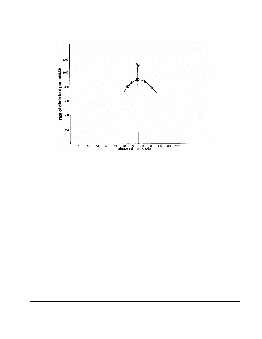
47
5/24/95
AC 90-89A
FIGURE 6.
Climb Airspeed and Altitude Graph
c.
Best Rate of Climb Speed Tests.
To deter-
mine the best rate of climb for the aircraft, the fol-
lowing procedures are suggested:
(1)
Perform the tests in smooth air, free
from thermal activity. Select an altitude (e.g., 1,000
feet AGL) as a BASE attitude. Use a heading 90
degrees to the wind and for the best results, reverse
the heading 180 degrees after each climb test.
(2)
Begin a full throttle climb well below
the predetermined BASE altitude and stabilize at a
preselected airspeed approximately 15 mph/knots
above the predicted best rate of climb speed. As the
aircraft passes through the BASE altitude, begin a
one minute time check. At the end of 1 minute,
record the altitude gained. Descend down below the
BASE altitude. Decrease the airspeed by 5 mph/
knots and run the test again. After each succeeding
test, the pilot should decrease the airspeed by 5 mph/
knots until reaching an airspeed that is 10 mph/knots
higher than the stall speed of the aircraft. Record
the airspeed and altitude gained for each climb on
a graph similar to figure 6.
(3)
The airspeed that shows the greatest
gain in altitude is the aircraft’s best rate of climb
speed (V
y
).
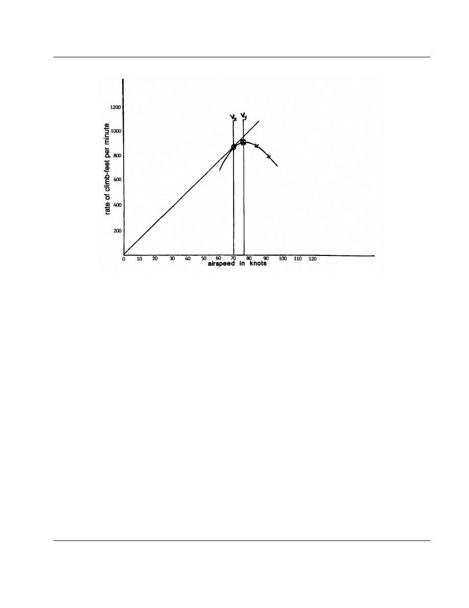
48
5/24/95
AC 90-89A
FIGURE 7.
Best Rate of Climb Speed Graph
d.
Best Angle of Climb Speed Tests.
(1)
Best angle of climb speed can be found
by using the same chart developed for the best rate
of climb tests. Draw a line (tangent) from the zero
rate of climb feet per minute (see figure 4) outward
to a point, on the rate of climb airspeed curve. Where
both lines touch, draw a line straight down to the
airspeed leg of the chart.
(2)
The airspeed that the line intersects is
the best angle of climb airspeed.
e.
Slow Flight Test.
(1)
For added safety, the slow flight tests
should be performed at 6,000 AGL or higher to allow
room for spin recovery. THE PRIMARY PURPOSE
OF THESE TESTS IS FOR THE PILOT TO
BECOME FAMILIAR WITH THE AIRCRAFT’S
HANDLING QUALITIES AT THE MINIMUM
GEAR UP/DOWN AIRSPEEDS AND POWER
SETTINGS.
(2)
The tests should be done with and with-
out flaps. Start the tests at an airspeed of 1.3 times
(X) the stall speed of the aircraft. Once the aircraft
is stabilized and maintaining its altitude, reduce the
airspeed by 5 mph/knots. Maintain the altitude. Keep
reducing the airspeed until approaching a stall.
(3)
Maintain 5 mph/knots above the pre-
viously determined stall speed. This figure is the ini-
tial slow flight airspeed. Practice with each flap set-
ting, noting its affect on the aircraft’s performance.
If the aircraft has retractable gear, test in all gear
and flap combinations. These tests will have to be
run later in the flight test program but with the AIR-
CRAFT AT GROSS WEIGHT to determine the
actual slow flight airspeed and stall speeds.
(4)
Remember, to help reduce the possibil-
ity of unplanned stalls in slow flight configurations,
avoid bank angles of more than 5 degrees. When
all the test data has been evaluated, and if the aircraft
is equipped with a stall warning horn or indicator,
set the stall warning at 5 mph/knots above the air-
craft’s highest stall speed.
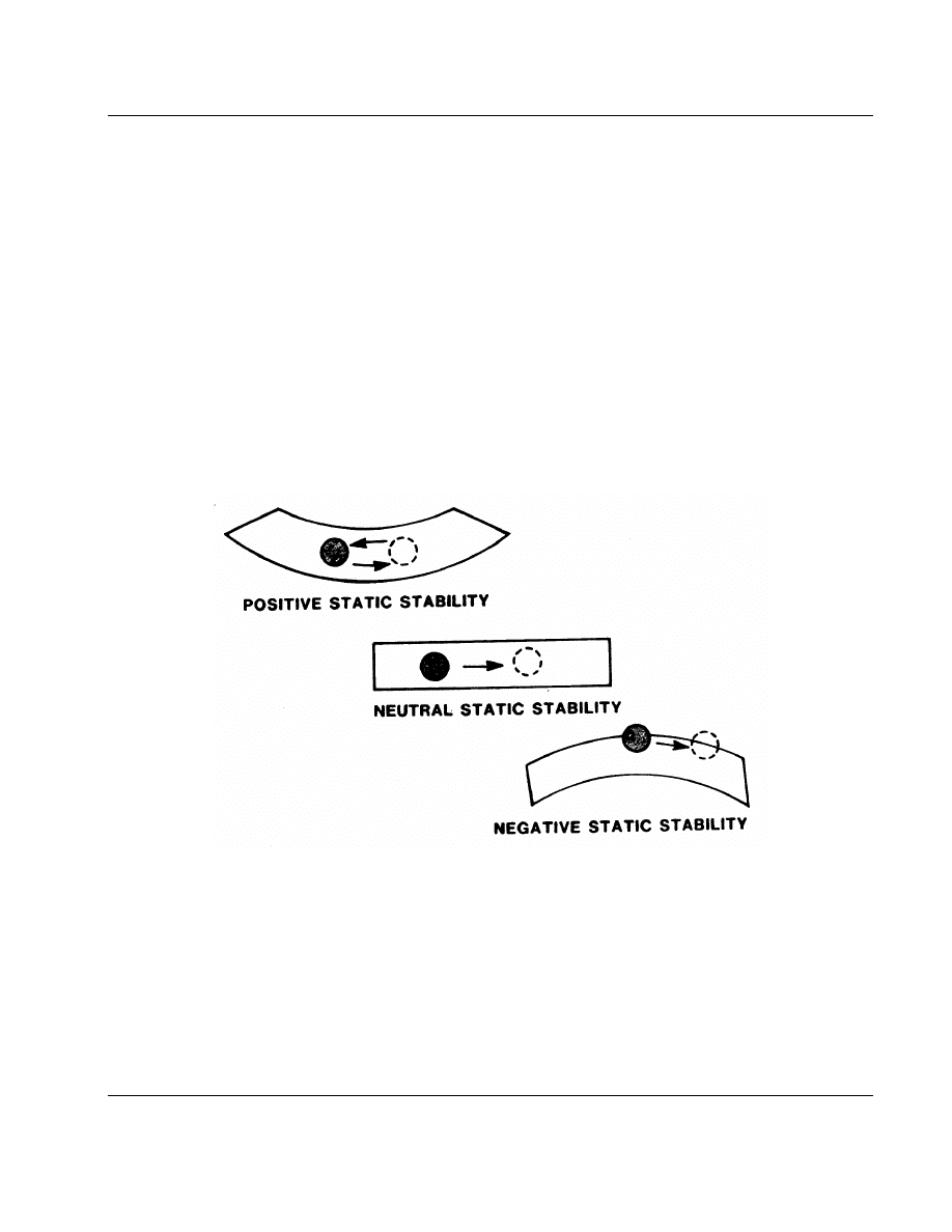
49
5/24/95
AC 90-89A
SECTION 3.
HOURS 21 THROUGH 35: STABILITY AND CONTROL CHECKS
‘‘A superior pilot uses his superior judgement to avoid those situations which require the use of superior
skill.’’ Old Aviation Proverb
1.
OBJECTIVE.
To determine the aircraft’s
stability limits and range of control.
2.
GENERAL.
Before attempting to satisfy the
requirements of Federal Aviation Regulations
§ 91.319 Aircraft Having Experimental Certificates:
Operating Limitations and declaring that the aircraft
is controllable throughout the normal range of
speeds, two things must be done.
a.
Perform another complete inspection of the
aircraft, including oil changes and fuel system filter
checks.
b.
Carry out a close examination of the stabil-
ity and control characteristics of the aircraft. Stability
and control checks will be centered around the three
axes of the aircraft: longitudinal or roll axis (aile-
rons), the lateral or pitching axis (elevators), and the
vertical or yaw axis (rudder).
c.
All tests need a starting point. The starting
point for stability and control checks is called the
state of equilibrium. An aircraft is said to be in a
state of equilibrium when it experiences no accelera-
tion and remains in a steady trimmed condition until
the force or moment balance is disturbed by an
atmospheric irregularity or by pilot input.
FIGURE 8.
Static Stability
3.
DEFINITIONS.
a.
Static Stability: (positive) is when an air-
craft tends to return to the state of initial equilibrium
position following a disturbance.
b.
Static Stability: (neutral) is when an aircraft
remains in equilibrium in a ‘‘new’’ position, follow-
ing a disturbance from an initial equilibrium position.
c.
Static Stability: (negative) is when an air-
craft tends to move further in the same direction as
the disturbance that moved it from the initial equi-
librium position (figure 8).
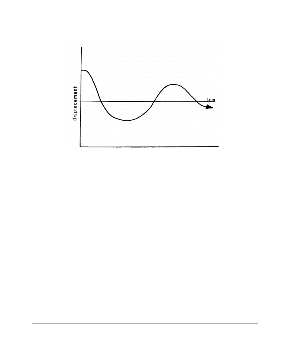
50
5/24/95
AC 90-89A
FIGURE 9.
Time
d.
Dynamic Stability: is the time history of the
movement of the aircraft in response to its static
stability tendencies following an initial disturbance
from equilibrium (figure 9).
e.
Test for Static Longitudinal Stability.
(1)
This test should be done first. All tests
should be conducted with the aircraft in the forward
of center CG. Climb to at least 6,000 feet AGL and
trim the aircraft for zero stick force in straight and
level flight at low cruising speed. (Note: Do not
retrim the aircraft once the test has begun.) Apply
a light ‘‘pull’’ force and stabilize at an airspeed about
10 percent less than the trimmed cruise speed. At
this reduced airspeed it should require a ‘‘pull’’ force
to maintain the slower speed.
(i)
If it requires a ‘‘pull’’ force, pull
a little further back on the stick and stabilize the
airspeed at approximately 20 percent below the ini-
tial cruise trim speed.
(ii)
If it requires a still greater ‘‘pull’’
force to maintain this lower airspeed, the aircraft has
POSITIVE STATIC LONGITUDINAL STABIL-
ITY.
(iii)
If at either test points, no
‘‘pull’’ force is required to maintain the reduced air-
speeds, the aircraft has NEUTRAL STATIC
LONGITUDINAL STABILITY.
(iv)
If either of these test points
require a ‘‘push’’ force to maintain the reduced air-
speed then the aircraft has NEGATIVE STATIC
LONGITUDINAL STABILITY.
(2)
Repeat another series of static longitu-
dinal stability tests using a ‘‘push’’ force on the con-
trol stick. At an airspeed 10 percent above the trim
cruise speed the control stick should require a
‘‘push’’ force to maintain the airspeed. If a ‘‘pull’’
force is required, the aircraft has NEGATIVE
STATIC LONGITUDINAL STABILITY.
WARNING: If the aircraft exhibits
negative static longitudinal stability,
seek professional advice on correct-
ing the problem before further flight.
(3)
After confirming the aircraft has posi-
tive STATIC longitudinal stability, the pilot can
check for positive DYNAMIC longitudinal stability
(short period). First, trim the aircraft to fly straight
and level at normal trim cruise speed. With a smooth,
but fairly rapid motion, push the nose down a few
degrees.

51
5/24/95
AC 90-89A
(4)
Quickly reverse the input to nose up
to bring the pitch attitude back to trim attitude. As
the pitch attitude reaches trim attitude, release the
stick (but guard it). The aircraft with positive
dynamic longitudinal stability will oscillate briefly
about the trim attitude before stopping at the trim
attitude position.
(5)
To test the aircraft for positive
DYNAMIC longitudinal stability (long period),
begin from trimmed, straight and level flight. With-
out re-trimming, pull (or push) the stick to a speed
about 5 mph/knots off trim and release the stick.
There is no need to stabilize at the new speed. Expect
the aircraft to oscillate slowly about the trim airspeed
a number of times before the motion dampens out.
If there is significant friction in the control system,
the aircraft may settle at a speed somewhat different
from the original trim speed.
(6)
If the amplitude increases with time,
the dynamic longitudinal stability is negative or
divergent. This is not necessarily dangerous as long
as the rate of divergence is not too great. It does
mean, however, the aircraft will be difficult to trim
and will require frequent pilot attention.
(7)
An aircraft with ‘‘NEUTRAL’’
dynamic longitudinal stability (long period) will con-
tinue to oscillate through a series of increasing/
decreasing airspeeds and never return to the original
trim airspeed.
f.
Lateral-directional Stability Control Tests.
Lateral (Dihedral Effect) and directional stability
tests are to determine if the aircraft can demonstrate
a tendency to raise the low wing in a sideslip once
the ailerons are freed. They also determine if the
rudder is effective in maintaining directional control.
CAUTION: This test may impose high
flight loads on the aircraft. Do not
exceed the design maneuvering speed
or any other airspeed limitation.
(1)
To check lateral and directional stabil-
ity, the aircraft should be trimmed for level flight
at a low cruise setting and an altitude above 5,000
feet AGL. Slowly enter a sideslip by maintaining
the aircraft’s heading with rudder and ailerons. The
aircraft should be able to hold a heading with rudder
at a bank angle of 10 degrees or the bank angle
appropriate for full rudder deflection. The control
forces and deflection should increase steadily,
although not necessarily in constant proportions with
one another (in some cases, rudder forces may
lighten), until either the rudder or the ailerons reach
full deflection or the maximum sideslip angle is
reached.
(2)
At no time should there be a tendency
toward a force reversal, which could lead to an over-
balance condition or a rudder lock.
(3)
Release the ailerons while still holding
full rudder. When the ailerons are released, the low
wing should return to the level position. Do not assist
the ailerons during this evaluation.
(4)
To check static directional stability,
trim the aircraft at a low cruise setting above 5,000
feet AFL. Slowly yaw the aircraft left and right using
the rudder. Simultaneously the wings should be kept
level by using the ailerons. When the rudder is
released, the aircraft should tend to return to straight
flight.
g.
Spiral Stability. This is determined by the
aircraft’s tendency to raise the low wing when the
controls are released in a bank. To test for spiral
stability, apply 15 to 20 degrees of bank either to
the left or right, and release the controls. If the bank
angle decreases, the spiral stability is positive. If the
bank angle stays the same, the spiral stability is neu-
tral. If the bank angle increases, the spiral stability
is negative. Negative spiral stability is not nec-
essarily dangerous, but the rate of divergence should
not be too great or the aircraft will require frequent
pilot attention and will be difficult to fly, especially
on instruments.
NOTE: Friction in the aileron control sys-
tem can completely mask the inherent spiral
characteristics of the airframe.

52
5/24/95
AC 90-89A
SECTION 4.
A WORD OR TWO ABOUT FLUTTER
‘‘Stay up on the edge of your seat.’’ Scott Crossfield, Test Pilot
1.
OBJECTIVE.
To understand the causes and
cures of the condition known as flutter.
2.
DESCRIPTION.
Flutter in an aircraft struc-
ture is the result of an interaction between aero-
dynamic inputs, the elastic properties of the structure,
the mass or weight distribution of the various ele-
ments, and airspeed.
a.
To most people, the word ‘‘flutter’’ suggests
a flag’s movement as the wind blows across it. In
a light breeze, the flag waves gently but as the wind
speed increases, the flags motion becomes more and
more excited. It takes little imagination to realize
if something similar happened to an aircraft struc-
ture, the effects would be catastrophic. The parallel
to a flag is appropriate.
b.
Think of a primary surface with a control
hinged to it (e.g., an aileron). Imagine that the air-
plane hits a thermal. The initial response of the wing
is to bend upwards relative to the fuselage.
c.
If the center of mass of the aileron is not
exactly on the hinge line, it will tend to lag behind
the wing as it bends upwards.
d.
In a simple, unbalanced, flap-type hinged
control, the center of mass will be behind the hinge
line and the inertial lag will result in the aileron being
deflected downwards. This will result in the wing
momentarily generating more lift, increasing its
upward bending moment and its velocity relative to
the fuselage. The inertia of the wing will carry it
upwards beyond its equilibrium position to a point
where more energy is stored in the deformed struc-
ture than can be opposed by the aerodynamic forces
acting on it.
e.
The wing ‘‘bounces back’’ and starts to
move downward but, as before, the aileron lags
behind and is deflected upwards this time. This adds
to the aerodynamic down force on the wing, once
more driving it beyond its equilibrium position and
the cycle repeats.
f.
Flutter can happen at any speed, including
take-off speed. At low airspeeds, however, structural

53
5/24/95
AC 90-89A
and aerodynamic damping quickly suppress the flut-
ter motion. But as the airspeed increases, so do the
aerodynamic driving forces generated by the aileron.
When they are large enough to cancel the damping,
the motion becomes continuous.
g.
Further SMALL INCREASES will
produce a divergent, or increasing oscillation, which
can quickly exceed the structural limits of the air-
frame. Even when flutter is on the verge of becoming
catastrophic it can still be very hard to detect. What
causes this is the high frequency of the oscillation,
typically between 5 and 20 Hz (cycles per second).
It will take but a small increase in speed (
1
⁄
4
knot
or less) to remove what little damping remains and
the motion will become divergent rapidly.
h.
Flutter also can occur on a smaller scale
if the main control surface has a control tab on it.
The mechanics are the same with the tab taking the
place of the aileron and the aileron taking the place
of the wing. The biggest difference are the masses
involved are much smaller, the frequencies much
higher, and there is less feed-back through the con-
trol system. This makes tab flutter more difficult to
detect. The phenomenon known as ‘‘buzz’’ is often
caused by tab flutter. Since flutter is more prevalent
at higher speeds, it is not recommended that the flight
test plan call for high speed runs within 10 percent
of red line.
i.
What can be done about it? Having
described how flutter happens, the following sugges-
tions should help reduce the possibility of it happen-
ing to the amateur-builder’s aircraft:
(1)
Perform a mass balance of all flight
controls in accordance with the designer/kit manu-
facturer’s instructions.
(2)
Eliminate all control ‘‘free play’’ by
reducing slop in rod end bearings, hinges, and every
nut and bolt used in attaching flight controls.
(3)
Ensure that all rigging and cable ten-
sion is set accurately to the design specifications
using a calibrated cable tensiometer.
(4)
Re-balance any flight control if it has
been repaired, repainted, or modified in any way.
NOTE: If the pilot experiences flutter, or
believes he did, reduce power immediately
and land as soon as possible. Do not attempt
further flight until the aircraft has been
thoroughly inspected for flutter induced
damage. This inspection should include all
wing/tail attach points, flight controls, their
attach points/hinges, hardware, control
rods, and control rod bearings for elongated
bolt/rivet holes, cracks, (especially rod end
bearings) and sheared rivets.
54
5/24/95
AC 90-89A
SECTION 5.
SPINS
‘‘Go from the known to the unknown -- slowly!’’ Chris Wheal, Military Test Pilot
1.
OBJECTIVE.
To determine if spin testing is
required.
NOTE: All FAA spin tests for type certifi-
cation require a spin chute attached to the
aircraft. Even though amateur-built aircraft
have no such certification requirement, use
of a spin chute during testing should be
considered.
2.
CAUTION.
a.
If the manufacturer/designer of the aircraft
has not demonstrated satisfactory spin characteristics
and safe recovery, avoid all types of high angle of
attack flight testing and placard the aircraft: ‘‘spins
prohibited.’’
b.
If the prototype aircraft has satisfactorily
demonstrated spin recovery and the builder’s aircraft
is identical to the prototype aircraft, the pilot may
confirm the aircraft will recover promptly from
inadvertent spin entries. Further tests to prove that
the aircraft will recover from a fully developed spin
(three turns or more) are not necessary unless the
aircraft is designed for, and will be routinely flown
in, aerobatic flight.
c.
During all spin tests, it is strongly rec-
ommended that the pilot wear a parachute and that
a quick release mechanism to jettison the canopy
or door be installed. If the pilot is unable to exit
the aircraft because of the design restraints, it is rec-
ommended that intentional spins not be conducted
even though the design has successfully dem-
onstrated spin recovery.
d.
If any modifications or alterations have
been made to the airframe’s original design or
configuration (e.g., adding tip tanks or fairings), it
is not safe to assume that the aircraft still has the
same spin recovery characteristics as the prototype
aircraft. Spins in a modified aircraft should not be
attempted without consulting a qualified test pilot
and/or flight test engineer.
e.
The pilot who conducts the spin tests should
have experience in entry into and recovery from fully
developed spins, preferably in makes and models
similar to the aircraft being tested. If the pilot needs

55
5/24/95
AC 90-89A
additional experience, aerobatic training with an
emphasis on spins from a qualified instructor is
highly recommended.
3. PLANNING THE FLIGHT.
At this point,
nearly all the preparatory work for spin testing has
been accomplished. Planning the next flight should
be identical to planning for the first flight through
stalls. IT IS EXTREMELY IMPORTANT THAT
THE CENTER OF GRAVITY OF THE AIRCRAFT
IS AT THE FORWARD CG LIMIT AND ANY
BALLAST USED SHOULD BE SECURELY
ATTACHED TO THE AIRCRAFT.
a.
The aircraft should be tested with landing
gear (if applicable) and flaps in the up position. The
pilot’s minimum entry altitude for these tests should
be no less than 10,000 feet AGL with the cockpit
secured.
NOTE: The following procedure is one way,
but not the only way, of conducting a spin
test and executing a recovery. Non-conven-
tional aircraft may require significantly dif-
ferent spin recovery control applications.
The pilot should evaluate these procedures
and determine if they are compatible with
the aircraft before attempting any spin test-
ing.
b.
The basic technique used to get a clean spin
entry is to continue to reduce airspeed at about a
1 mph/knot a second rate in level flight, carburetor
heat on, and the power at idle.
(1)
As the aircraft stalls, APPLY FULL
RUDDER in the desired spin direction, followed
immediately by full aft movement of the control stick
keeping the ailerons neutral.
(2)
The transition from a horizontal to a
vertical flight path takes approximately three or four
turns and is referred to as the incipient stage of the
spin.
(3)
During the incipient spin, the dynamic
and inertia forces have not achieved equilibrium.
Many aircraft can recover from the incipient spin
phase, but may not be able to recover from a steady
spin.
(4)
The normal spin recovery technique is
to apply full rudder opposite to the direction of yaw
(check the turn needle). Move the control stick
smoothly and fairly rapidly forward towards the
instrument panel until the rotation stops.
(5)
Quickly center the rudder and ease out
of the dive. Do not attempt to pull up too rapidly
because the structural limits of the aircraft can easily
be exceeded, or the aircraft can stall again. Recover
from the first deliberate spin after a half a turn.
c.
If the aircraft is not built for aerobatics,
no further spin testing is required, It is recommended
the instrument panel be placarded ‘‘SPINS PROHIB-
ITED.’’
d.
If further spin testing is required, it is
strongly recommended the services of a professional
flight test pilot be used.

56
5/24/95
AC 90-89A
SECTION 6.
ACCELERATED STALLS
‘‘Does it pass the Common Sense test?’’ U.S. Air Force, Thunderbird
1.
OBJECTIVE.
To further explore the stall
characteristics of the aircraft.
a.
An accelerated stall is not a stall reached
after a rapid deceleration. It is an in-flight stall at
more than one g, similar to what is experienced in
a steep turn or a pull up.
NOTE: Do not attempt this or any other
extreme maneuver unless the designer or kit
manufacturer has performed similar tests on
a prototype aircraft identical to the ama-
teur-builder’s aircraft.
b.
The two standard methods for accelerated
stalls are the constant g (constant bank) and constant
speed (increasing bank). Most preferred of the two
is the constant bank method in which the airspeed
is decreased and the angle of bank is held constant,
until the aircraft stalls. It is the most preferred
because the potential violence of any accelerated stall
is largely governed by the increasing g load and air-
speed.
c.
As with every test, plan the sequence of
events. Start with small bank angles -- 30 degrees
will produce 1.15 g. Decelerate slowly, ball in the
center, do not over control. Work up incrementally
to a two g, 60 degree bank.
d.
The aircraft does not have to develop a deep
stall each time. The pilot needs only to record the
airspeed and bank angle in which the aircraft hits
the pre-stall buffet. Recover by adding power and
reducing the angle of bank.

57
5/24/95
AC 90-89A
CHAPTER 6.
PUTTING IT ALL TOGETHER: 36 HOURS TO —————?
‘‘Beware of false knowledge; it is more dangerous than ignorance.’’ George Bernard Shaw
SECTION 1.
MAXIMUM GROSS WEIGHT TESTS
1.
OBJECTIVE.
To develop aircraft perform-
ance data across the weight and CG ranges.
a.
Up until this point, all tests have been per-
formed well below the test aircraft’s maximum gross
weight, with the possible exception of single seat
aircraft designs. A complete series of flight tests at
maximum gross weight from stalls, rates of climb,
angles of climb, stability, retraction tests, slow flight,
through accelerated stalls should be investigated.
b.
These tests should demonstrate that the air-
craft has been successfully flown throughout the CG
range, and will operate in and at the full range of
aircraft weights from minimum to full gross weight.
The findings should be documented in the aircraft’s
flight manual.
c.
Each phase of the testing should be done
slowly, incrementally, with the same careful atten-
tion to detail that should characterize all the flight
testing.
d.
Increases in the aircraft weight should be
done in a series of steps. Usually, 20 percent incre-
ments of the maximum payload (e.g., sandbags, lead
shot) are added in the aircraft to simulate passengers
or baggage weight. The pilot should carefully weigh
and secure the ballast. A new weight and balance
and CG location must be worked for each new
increase in weight. Stop testing when the aircraft’s
maximum gross weight is reached.
e.
The testing up to this point has been done
at, or near, the forward CG limit. During these tests,
the CG should be slowly, but progressively, moved
aft between each test flight. Limit the change to the
CG range to about 20 percent of the range. Again
the pilot should weigh the ballast and work a new
weight and balance for each flight. With each CG
change the aircraft longitudinal static stability and
stall characteristics should be carefully evaluated by
using the same technique discussed earlier. Stop test-
ing when the designer’s or kit manufacturer’s aft CG
limit is reached.
f.
If the aircraft develops either a neutral or
negative longitudinal stability problem, or the air-
craft displays unsatisfactory stall characteristics at
any CG location being tested, STOP FURTHER
TESTING!!
g.
These tests should confirm the designer’s
aft CG limit or establish the last satisfactory aft CG
location. If the aft CG range is not satisfactory, con-
sult with the kit manufacturer, aircraft designer, or
a flight test engineering consultant.
h.
The pilot should avoid the temptation to
take a live ballast weight up for a ride for three rea-
sons:
(1)
The aircraft has not been proven safe
for the higher gross weights.
(2)
The pilot and passenger are at great
risk. It is a sure sign the pilot has become complacent
and sloppy in his flight test program.
(3)
The pilot will be breaking a contract
(Operating Limitations) with the U.S. Government,
which is known not to look kindly on such matters.
i.
Pilots should ensure that the added ballast
weight in the cockpit is secured. A seat belt over
some sand bags will not stop the weight from shifting
and getting loose in a cockpit. The last thing a test
pilot needs is a 20-pound lead-shot bag free in the
cockpit during a climb test, a landing, or a spin. Tie
each weight down individually, and cover all the
weights with a cargo net.
j.
Ensure the ropes/nets and airframe attach
points are strong enough to take the added load.
Make sure the passenger seat can take that much
localized weight safely.
k.
The maximum gross weight test results
should be recorded in the flight manual. If there are
any changes to the stall speed initially marked on
the airspeed indicator, it should be changed to reflect
the aircraft stall speed at maximum gross weight.
58
5/24/95
AC 90-89A
SECTION 2.
SERVICE CEILING TESTS
‘‘Man is made for error; it enters his mind naturally and he discovers a few truths only with the greatest
effort.’’ Frederick the Great
1.
OBJECTIVE.
To determine the highest alti-
tude at which an aircraft can continue to climb at
100 feet per minute (Service Ceiling).
a.
Pilots who wish to determine the actual
service ceiling of their aircraft are offered the follow-
ing suggestions:
(1)
Ask the local Flight Standards District
Office (FSDO) to amend the Operating Limitations
to permit a climb to the aircraft’s service ceiling,
if that altitude is above 18,000 feet.
(2)
Contact the local Flight Service Station
(FSS) or ATC facility, and reserve a time and air-
space to make the test.
(3)
Install a transponder (reference FAR
§ 91.215) or get a waiver.
(4)
Install a portable oxygen bottle, if plans
are to go above 12,000 feet. (Recommend the pilot
becomes familiar with the symptoms and cures of
hypoxia and hyperventilation.)
(5)
Review the engine manufacturer’s mix-
ture leaning procedures.
(6)
Maintain communications with an air
traffic facility at all times.
b.
The climb to the aircraft service ceiling
should be made in a series of step climbs during
which engine performance, temperatures and pres-
sures are recorded. At the slightest indication of
engine performance or aircraft control problems, the
pilot should terminate the test and return to the air-
port.
59
5/24/95
AC 90-89A
SECTION 3.
NAVIGATION, FUEL CONSUMPTION, AND NIGHT FLYING
‘‘That’s one small step for man, one giant leap for mankind.’’ Neil Armstrong
1.
OBJECTIVES.
To ensure all the small but
important aspects of flight have been tested and
found reliable.
a.
The Magnetic Compass.
The magnetic
compass should have been checked for accuracy
prior to the first flight. However, the addition and
removal of equipment, changing of wire bundle rout-
ing, and other airframe modifications may have
affected the accuracy of the instrument. The follow-
ing recommendations are offered:
(1)
The magnetic compass can be checked
for accuracy by using a compass rose located on
an airport, or using a hand held ‘‘master compass.’’
The master compass is a reverse reading compass
with a gun-sight mounted on the top of it. With the
aircraft facing north and the pilot running the engine
at 1,000 rpm, a second individual standing 30 feet
away facing due south ‘‘shoots,’’ or aligns, the mas-
ter compass with the aircraft’s centerline. Using hand
signals, the pilot aligns the aircraft with the master
compass. The pilot then runs the aircraft engine up
to approximately 1,700 rpm to duplicate the aircraft’s
magnetic field and reads the compass.
NOTE: Conventional gear aircraft builders
will have to position the magnetic compass
in a straight and level position for this test.
Raise the tail or mount the compass level
with the horizon.
(2)
If the aircraft compass is not in align-
ment with the master compass (start at north), correct
the error by adjusting the north/south brass adjust-
ment screw with a non-metallic screwdriver (can be
made out of stainless steel welding rod, brass stock,
or plastic) until the compass reads correctly. Go to
the reciprocal heading (south) and remove half the
error. On the east/west headings, use the other brass
adjustment screw to make the corrections using the
same procedures that was used to correct the north/
south errors.
(3)
Check again for errors at each cardinal
heading. Record the last readings and prepare a com-
pass correction card. The maximum deviation (posi-
tive or negative) is 10 degrees on any one heading.

60
5/24/95
AC 90-89A
(4)
If the compass cannot be adjusted to
meet this requirement, install another one. If the new
compass is not available, try a different location in
the cockpit, away from all ferrous metals and elec-
trical bundles.
NOTE: A common error that affects the
compass’s accuracy is the mounting of mag-
netic compass on/in the instrument panel
with steel machine screws and nuts rather
than brass.
(5)
If the aircraft has an electrical system
it is recommended that two complete compass checks
be made, one with all electrical accessories on (e.g.,
radios/nav lights), and one with all electrical acces-
sories off. If the deviation in level flight is more
than 10 degrees on any heading with the accessories
on, make up a separate compass correction card that
shows the magnetic heading with the equipment on.
(6)
Record the findings in the aircraft’s
flight manual and create a compass correction card,
mounting it near the magnetic compass in the cock-
pit. Make two cards; one with radios on and one
with radios and non essential electrical accessories
off.
b.
Very High Frequency (VHF) Omni-direc-
tional Radio Range (VOR) Check.
The best guide
to check the accuracy of the VOR on board equip-
ment is the VOR Receiver Check found in the Air-
man’s Information Manual (AIM), available from the
Superintendent of Documents. The following is an
abbreviated summary of the VOR procedure in the
AIM.
(1)
For a ground test of the VOR, a VOR
Test Facility (VOT) must be used. To use the VOT
service, tune in the VOT frequency on the VOR
receiver. It is normally 108 Mhz. With the Course
Deviation Indicator (CDI) centered, the omni-bear-
ing selector should read 0 degrees with the to/from
indicator showing ‘‘from,’’ or the omni-bearing
selector should read 180 degrees with the to/from
indicator showing ‘‘to.’’ The maximum bearing error
should never be more than four degrees.
NOTE: The VOT facilities closest to the
flight test location can be found in the Air-
port/Facility Directory. It is available by
subscription from NOAA Distribution
Branch N/CG33, National Ocean Service,
Riverdale, MD 20737, or contact the nearest
FAA FSS.
(2)
For the airborne test, select a prominent
ground point along the selected radial, preferably
more than 20 miles from the VOR. Maneuver the
aircraft directly over the point at a reasonably low
altitude.
(i)
Note the VOR bearing indicated
by the receiver when over the ground point. The
maximum permissible variation between the pub-
lished radial and the indicated bearing is six degrees.
(ii)
If the aircraft has dual VOR’s, the
maximum permissible variation between the two
receivers is 4 degrees.
c.
Fuel Consumption:
a good indication of
how much the engine is working for each rpm pro-
duced. For a new or recently overhauled engine, the
fuel consumption should improve each flight hour
until the engine finishes its ‘‘break in’’ period, i.e.,
after approximately 100 hours of operation.
(1)
To determine the aircraft fuel consump-
tion, lay out a race track course with 8 to 10 mile
legs. If the aircraft has one fuel tank or cannot switch
tanks, do the following: Determine the approximate
fuel burn to reach 1,000, 3,000, 5,000, 7,000, and
9,000 feet of altitude. With full tanks, climb to 3,000
feet and run the race track course for half an hour
at 55 percent power.
(2)
Land and measure the fuel used by dip-
ping the tanks with a calibrated fuel stick, or by add-
ing measured amounts of fuel to the tank until the
tank is full. Subtract the approximate fuel burn to
altitude, and multiply the remainder by two to get
the fuel burn per hour.
(3)
The tests are much easier and the
results more accurate if the aircraft has two
independent fuel tanks. Take-off on one tank and
switch to the opposite tank at the test altitude. At
the completion of the test, switch back to the first
tank; land and measure the amount of fuel added
in both tanks and multiply the quantity by two to
get the amount of fuel used per hour.
(4)
Run the same test at 65 percent and
75 percent power at the same altitude, using the same
procedures. Move up to the next altitude and run
the same tests.

61
5/24/95
AC 90-89A
d.
Night Operations:
should be conducted in
accordance with the aircraft’s FAA Operating
Limitations and limited to normal climbs and
descents (e.g., 500 feet per minute), pitch angles of
less than 5 degrees, straight and level flight, and
coordinated turns of no more than 20 degrees of bank
angle.
(1)
The main concern for night testing
should be the availability of a horizonal reference
(e.g., bright moon or artificial horizon).
(2)
Prior to every night flight, ensure a reli-
able flashlight with fresh batteries and a set of
FLIGHT TEST PLAN procedures are on board.
Some night testing requirements should have already
been determined on the ground. For example:
(i)
The electrical load review of all
the lights, pumps, instrumentation, and avionics did
not exceed 80 percent of the aircraft’s charging sys-
tem capacity.
(ii)
The cockpit instrumentation light-
ing is adequate and was tested for reliability of oper-
ation during daytime flights.
(iii)
The pilot has at least
1
⁄
2
hour of
night time taxiing the aircraft. This practice is needed
to familiarize the pilot with a different operating
environment. Do not exceed engine operating
temperatures during taxiing.
(iv)
The position and brightness of
instrument panel lights, anti-collision strobe lights,
and rotating beacons will not adversely affect the
pilot’s night vision.
(3)
A suggested night flight test plan is a
series of takeoffs and landings and traffic pattern
entries and exits. The tests should begin while there
is still enough light to read a newspaper and transi-
tion to true night flying. The actual night flight will
consist of an evaluation of the effectiveness of the
taxi/landing light system, during taxi, take-off, and
landing. The pilot should note any glare on the wind-
shield or light flicker on the instrument panel.

62
5/24/95
AC 90-89A
THIS PAGE INTENTIONALLY LEFT BLANK

63
5/24/95
AC 90-89A
CHAPTER 7.
THOUGHTS ON TESTING CANARD TYPE AMATEUR-
BUILT AIRCRAFT
‘‘FLY.’’ Jonathan Livingston Seagull
SECTION 1.
CANARDS
1.
OBJECTIVE.
To discuss canard flight
characteristics.
a.
Canard configured aircraft generally fall
into 2 categories: the LongEze design (pusher prop,
tandem seats) and the Quickie (Q2) design (tractor
prop, side by side seats). Canard configured aircraft
do not ‘‘stall’’ in the conventional sense. All success-
ful ‘‘loaded canard’’ designs have the angle of
incidence (AOI) of the canard set higher than the
main (rear) wing.
b.
As the airplane’s angle of attack (AOA)
increases, the canard should stall first, lowering the
AOA of the main (rear) wing. Since the rear wing
doesn’t stall, a characteristic ‘‘buck’’ or ‘‘nod’’ takes
place. Full aft stick results in the canard alternately
stalling and flying while the rear wing never reaches
it’s critical AOA and continues to fly. This self-limit-
ing stall characteristic makes a properly designed and
built canard aircraft un-spinable. It should be noted,
however, that the accident rate for canard designs
are approximately the same as conventional designed
amateur-built aircraft because of the following:
(1)
During take-off, the transition from
ground roll to flight can be a more critical procedure
in some canards as compared to more conventional
designs.
(2)
Some canards with combinations of CG
and pitch control sensitivity will be more likely to
over rotate at lift-off.
(3)
Some canards have less visible air-
frame structure in front of the pilot and in his periph-
eral vision. Others have more than enough. These
differences in design can produce a different ref-
erence frame for pilots with many hours of conven-
tional aircraft time and may cause initial errors in
pitch attitude, such as the nose too high on take-
off and landings.
(4)
In addition, canard aircraft by design
have very different take-off characteristics than
conventional configured aircraft. Canard aircraft
with pusher propellers need a substantially higher
rotation speed on take-off.
(5)
To rotate a conventional design air-
craft, all that is required is enough airspeed to pro-
vide sufficient control to attain a positive angle of
attack due to the long moment arm from the main
gear (the axis of rotation) to the tail, a relatively
small amount of lift is required. This lift, generated
at a relatively low airspeed, makes it possible to
rotate the aircraft into the take-off position slightly
below flying speed. Allow the aircraft to accelerate
to flying speed and lift off.
(6)
In contrast, the canard nose wheel will
stay firmly on the ground until an airspeed is reached
at which the canard, with full up elevator, can gen-
erate enough lift to equal the following:
(i)
the load carried by the nose
wheel, plus
(ii)
the nose down moment caused by
the friction of the nose and main gear tires with the
surface, and the down-thrust vector provided by the
propeller during the take-off roll.
(7)
Since the main wing may reach flying
speed before the canard, the nose wheel will stay
firmly on the runway until take-off speed is reached.
Rotation will then occur, and the aircraft will literally
jump off the ground.
(8)
Canards with a thrust line above the
CG will have appreciable pitch trim change with
power. Forward stick motion is required when power
is reduced. While this may not be of any consequence
to an experienced pilot, it can be a serious surprise
to an unwary and inexperienced pilot. This unfamil-
iar flight characteristic might cause pilot-induced
pitch oscillations with disturbing consequences under
some conditions (e.g., an aborted take-off).
(9)
Due to its unique design, the canard
aircraft needs a higher nose up attitude when landing
compared to conventional configured aircraft. Many
canard pilots are reluctant to raise the nose high on

64
5/24/95
AC 90-89A
landing due to the limited forward visibility while
the nose is up. Consequently, many canard pilots
tend to make their approach angle shallow. This shal-
low angle results in approach speeds quite a few
knots faster than what is necessary. For pilots who
prefer visibility to shorter runways, it is rec-
ommended that canard designed aircraft be tested
on runways a minimum of 1,000 feet longer than
what would be used for a conventional aircraft of
the same horsepower and performance capability.
Longer runways should be used until the pilot
becomes more experienced with the landing
characteristics of the aircraft.
(10)
If the nose is held at a too high an angle
on landing, the canard will stall while the main wing
is still generating lift. The stalled canard will drop
the nose rapidly onto the runway with enough force
to damage the nose gear.
(11)
Quickie (tractor engine designs)
configured canard designs have a limited ability to
rotate nose up while on the ground. This tends to
increase takeoff speeds because the canard and the
main wing angle of attack are limited while the air-
craft is on the ground. That is why this design
appears to ‘‘levitate’’ off the ground without much
apparent pitch change.
(12)
Some canard designs are very sensitive
to rain or other types of contamination on the leading
edge and/or top of the airfoil. Contamination in the
form of water droplets, frost, crushed insects, or even
poorly applied paint will disturb the laminar flow
over the canard and lift is lost. When decreasing lift
over drag (L/D) performance, the chances for an
accident increase.
2.
FLIGHT TEST CONSIDERATIONS.
Technically, a canard type aircraft cannot stall, or
at least it will not stall in the normal fashion. A
pilot testing the aircraft for stability characteristics
should approach such testing with caution in mind.
a.
Under certain conditions, usually consist-
ing of aft c.g. problems, the main wing may stall
before the canard surface. In this case, extreme pitch-
up can occur until the canard surface or strakes stall.
The aircraft would then pitch down to a near-level
attitude, however the airspeed would be approaching
zero and the angle of attack could approach or exceed
45 degrees. This condition (high-alpha), could be so
stabilized, with the aircraft in a deep stall, that recov-
ery might not be possible.
b.
Testing for pitch stability in a new design
or a just-completed aircraft built from a kit or from
plans is a requirement the pilot needs to consider
prior to carrying passengers. Pitch stability tests are
conducted to ensure that the aircraft does not exhibit
any dangerous flight characteristics but must be
approached and conducted in a logical and sensible
manner.
(i)
Positive pitch stability is exhib-
ited when the aircraft trimmed for hands off level
flight, returns to that state when a control force is
applied and released.
(ii)
Neutral pitch stability is achieved
when the aircraft remains in the pitch attitude
attained when a control force is applied.
(iii)
Negative pitch stability is dem-
onstrated when the aircraft departs from the pitch
attitude attained when a control force is applied and
continues to increase in amplitude.
c.
The aircraft should be weighed and the c.g.
carefully calculated. At the same time, determine the
weight needed and the moment calculated to load
the aircraft at the most forward and aft c.g. limits
recommended by the designer. Beginning at the most
forward c.g., trim the aircraft to a hands off condition
and slowly reduce the power, maintaining altitude
by increasing pitch attitude. When the stick reaches
the full aft position, momentarily release the back
pressure followed by full aft stick. The aircraft, in
demonstrating positive stability, should return to its
original pitch attitude and remain there. The aircraft
should display positive stability characteristics.
d.
Other tests may be conducted by adjusting
the c.g. further aft and observing the tendency of
the aircraft. At some point near the aft c.g. limit,
you may experience neutral stability, or the point
where the aircraft no longer recovers by itself from
the upset. Moving further aft in the c.g. range from
this point will cause the aircraft to diverge from the
trim path in the direction of the upset (neutral stabil-
ity).
e.
Some designers and builders have installed
adjustable, moveable ballast containers in the aircraft
to allow the c.g. to be adjusted forward or aft during
flight. If testing is to be accomplished outside the

65
5/24/95
AC 90-89A
recommended range, it is advisable to consider the
installation of a ballistic recovery system or spin
chute system. In addition, the pilot should make a
decision about leaving the aircraft if the test becomes
untenable.

66
5/24/95
AC 90-89A
THIS PAGE INTENTIONALLY LEFT BLANK
67
5/24/95
AC 90-89A
CHAPTER 8.
ULTRALIGHT AIRFRAME INSPECTION
‘‘You can learn 10 things by learning one.’’ Japanese proverb
SECTION 1.
DIFFERENCES
1.
OBJECTIVES.
To serve as additional
resource for ultralight test pilots and to help the new
owner develop a flight test plan for the ultralight.
2.
DEFINITION.
The term ‘‘Ultralight’’ means
a fixed wing vehicle that is powered by a conven-
tional 2 or 4 cycle, gasoline powered engine and
is operated under Part 103. It has one seat and does
not exceed 254 pounds, excluding floats and safety
devices. In addition, the ultralight can be unpowered,
in which case the weight is restricted to 155 pounds.
The powered ultralight’s fuel capacity cannot exceed
5 U.S. gallons. The vehicle should not be able to
exceed 55 knots calibrated airspeed at full power
and level flight and cannot exceed a power-off stall
speed of 24 knots calibrated airspeed. The term also
includes two place ultralight training aircraft of 496
pounds or less operated under either the EAA or
USUA exemption to FAR Part 103.
a.
Be aware that both single and dual seat
ultralights in this performance class are not restricted
only to FAR Part 103 operation. If they qualify, they
can be operated under FAR Part 91, if they meet
§ 21.191(g) amateur-built category or § 21.191(h)
operating kit built aircraft in primary category. Only
single seat ultralights of less than 254 pounds empty
weight, however, can operate legally under FAR Part
103.
b.
Many in the general aviation community
view amateur-built and ultralights as one and the
same design category, therefore all flight testing
procedures should be identical. While in many cases
this assumption is true, there are several major dif-
ferences between the two designs.
(1)
Most ultralights are assembled from
complete kits, unlike amateur-built aircraft of which
the major portion (51 percent) of the aircraft and
its component parts are manufactured by the builder.
Most of the kit/ultralight manufacturer’s pilot operat-
ing handbooks/flight manuals are usually accurate
and address the majority of the information covered

68
5/24/95
AC 90-89A
in the first eight chapters of this AC. The FAA rec-
ommends the pilot’s operating handbook always be
consulted by the new owner prior to flight.
(2)
The changes in ultralight ownership are
more frequent than amateur-built and general avia-
tion aircraft ownership. Although the ultralight is
‘‘used,’’ the new owner is usually unfamiliar with
the its operating characteristics. A comprehensive
flight testing/training program should be a high prior-
ity safety consideration of the new owner.
(3)
New flying skills should be developed.
Each ultralight pilot/owner should address the effects
smaller size, lighter wing-loading, lower weight, and
higher drag designs have on low-speed flight.
c.
Due to these differences, the FAA rec-
ommends that each ‘‘new’’ ultralight owner design
a FLIGHT TEST PLAN regardless if the ultralight
was bought, used, and/or the ultralight has a Flight
Manual supplied by the manufacturer. The ultralight
FLIGHT TEST PLAN does not have to be as exten-
sive as the one recommended for amateur-built air-
craft but should address all flight conditions and
emergencies called out in the ultralight’s flight man-
ual.
d.
With these differences in mind, the next
three chapters will address problems associated with
both NEW and USED ultralight flight testing. Chap-
ter 8 will address pre-test flight inspection, chapter
9 will cover engine and fuel system operation and
inspection, and chapter 10 will cover ultralight flight
testing.
e.
In keeping with that professional approach
towards flight testing, it is suggested that a FLIGHT
TEST PLAN and other relevant safety recommenda-
tions found in the chapters 1 through 7 be adopted
by the ultralight owner/operator prior to test flying
a new or used ultralight.
SECTION 2.
THE TEST PILOT
‘‘There is always a harder way to flight test an aircraft, but that path does not need to be followed. ’’
George Kaseote, FAA Test Pilot
1.
GENERAL.
Whether the ultralight is brand
new or used, it needs to be properly evaluated. A
new owner should enlist the services of an experi-
enced ultralight flight instructor who is authorized
to give dual instruction under the EAA or the USUA
exemption.
a.
The instructor should test fly the ultralight
only after it has been properly assembled, inspected,
engine run-in, and taxi tests have been performed.
It is not recommended that a ‘‘new’’ pilot and a
new/used ultralight ‘‘learn’’ to fly together.
b.
The test pilot should be experienced and
competent. He/she should have made a minimum of
100 solo flights in similar make, model, and type
of ultralight and must follow the FLIGHT TEST
PLAN exactly. The FLIGHT TEST PLAN should
examine the ultralight and its performance capability,
beginning with the pre-flight inspection and ending
only after the test pilot has explored the ultralight’s
published flight envelope as described in the flight
manual.
SECTION 3.
PRE-FLIGHT AIRFRAME INSPECTION
1.
GENERAL.
a.
Ultralight owners should remember that the
light-weight, thin wall tubing design of an ultralight
fuselage/wing structure is particularly susceptible to
metal fatigue. When aluminum tubing has been
stressed beyond its elastic limit, it takes on a chalky
white appearance (corrosion) at the point of highest
stress. Warpage and deformation are other signs of
high stress points and once discovered, the ultralight
should be grounded until the damaged is repaired.
b.
The tolerance limit of a tube or fitting can
be significantly lowered by over-torquing a bolt. If
a bent or damaged support tube or structure is not
repaired, the bend or dent will become a crack, and
ultimately the crack will become a structural failure.

69
5/24/95
AC 90-89A
NOTE: If a used ultralight has been pur-
chased, it is highly recommended that the
owner perform a detailed acceptance inspec-
tion on the aircraft assisted by an experi-
enced individual who is familiar with the
make and model aircraft. It is also rec-
ommended that all existing hardware (e.g.,
nuts, bolts, springs) be replaced with new
aviation quality hardware.
c.
If possible, remove the fabric envelope and
check the airframe structure underneath for dents,
cracks, and corrosion. Check the top and bottom of
the spars for compression (wrinkled metal) damage.
Double check all wings, landing gear, strut, engine,
and tail surface attach points for wear, elongated
holes, or damage.
d.
If any previous repairs are found, check
with the manufacturer to see if damage in that area
can be repaired and if the repair that was made is
airworthy.
2.
CHECKLIST.
Each ultralight FLIGHT TEST
PLAN should include a pre-flight inspection
CHECKLIST. The CHECKLIST should include a
step-by-step approach to inspection that covers all
the manufacturer inspection items as well as the fol-
lowing suggested items starting at the landing gear.
a.
Landing Gear.
The landing gear is the last
part of the light-weight aircraft to leave the earth
and the first part to arrive. Since the majority of
these aircraft fly from unimproved strips, the stress
on the gear is high. The checklist should include
inspection items recommended by the manufacturer
and inspection for the following:
(1)
The condition of the landing gear attach
points and alignment of the landing gear and wheels
to the longitudinal axis of the fuselage. If the attach
points are mis-aligned, the landing gear will not track
in a straight line and this will affect take-offs and
landings.
(2)
Elongated bolt-holes, loose AN hard-
ware, bent tubing, condition and attachment of
wheels, wheel bearings, tire inflation, tire condition
and brakes.
(3)
Brake condition and operation, includ-
ing chafing of brake lines/cables against the gear
struts.
(4)
Condition and operation of the steer-
able nose gear, if applicable.
(5)
Condition and attachment of the tail
wheel/skid, if applicable.
b.
Wing Assembly.
The vast majority of
ultralight aircraft use a man-made sailcloth material
stretched over a tubular frame. This type of fabric
is susceptible to ultra-violet radiation from the sun.
If left unprotected, it can become unairworthy in less
than 6 months. The checklist should include the fol-
lowing inspection items:
(1)
Ensure the sailcloth has not suffered
any tears, or abrasion, due to wear or foreign object
damage.
(2)
Check the sailcloth for obvious ultra-
violet (UV) degrading of fabric strength by examin-
ing the condition of the fabric on top of the wing.
Compare it to the fabric on the bottom of the wing.
If the top wing fabric shows a significant difference
in color (faded), the fabric should be tested for
strength with a fabric tester (Maule or Quicksilver)
to see if it tests within the manufacturer’s serviceable
limits. If no minimum service limits are listed, the
fabric should test out at 46 pounds, or 70 percent
or more, of its original tensile strength, whichever
is greater, to be considered airworthy. If the fabric
fails the tests, it must be replaced before further
flight.
(3)
Flying and landing support cables
should be checked for tension, routing, attach points,
and condition. Scrutinize the swaged cable ends. It
is recommended that a red reference mark (nail pol-
ish works fine) be painted on each of the cables abut-
ting the swaged end. If the cable is growing, i.e.,
a gap forming between the swaged end and the
painted referenced mark, there is an impending fail-
ure of the swaged terminal. Do not fly the aircraft
until the cable is replaced.
(4)
Flight control cables should be checked
for frayed wires and proper routing. Run a rag over
all of the flying and landing wires and control cables
(wings and tail). If the cloth snags, this may indicate
a frayed wire which demands further inspection. If
possible, bend the cable to form a ‘‘U’’ and inspect
for internal broken wires. Also, check the cable pul-
leys for wear and operation. Extreme wear patterns

70
5/24/95
AC 90-89A
on pulleys indicate misrouting and must be corrected
prior to flight.
(5)
Check wing leading/trailing edge, wing
struts, aileron, flaps, spoiler hinges and attach points
for loose rivets, cracks, elongation and wear. Ensure
that all hardware (nuts and bolts) are of aviation
quality.
(6)
Ensure that the bungee, or return
springs for wing spoilers (if applicable), are service-
able and will keep the spoiler down flat against the
top of the wing when not being deployed.
(7)
Check the aircraft’s flight controls rig-
ging every time the aircraft is re-assembled. It is
recommended that the cables/rigging for easier
assembly be color coded (e.g., red to red, blue to
blue).
(8)
Check for corrosion on all metal sur-
faces. Corrosion on aluminum usually appears as a
white powder, rough to the touch. On steel parts,
corrosion takes the common form of rust. Dissimilar
metal corrosion occurs when two different types of
metal make surface contact. To obtain additional
information on corrosion and treating it, refer to FAA
AC 43.9, ‘‘Corrosion Control for Aircraft.’’
(9)
Make sure the leading edge of the wing
and tail surfaces are clean and free of insects, grass,
or mud prior to flight.
c.
Fuselage Assembly.
The fuselage is the
backbone of the light-weight aircraft. All the flight
and ground operating stresses encountered by the
wings, tail, landing gear, and engine are transferred
to the fuselage at the attach points. Exercise extra
care when examining these high stress areas because
failure of any of these attach points and associated
hardware will cause catastrophic structural failure.
(1)
Flight controls should be checked for
proper operation, travel, and condition of the stops.
There should not be any sharp bends in the flight
control cables.
(2)
Check engine controls for proper oper-
ation; they should be free of bends and properly
secured. Ensure that all control cables are securely
clamped to the fuselage to prevent the cable from
slipping, hence not transferring the desired move-
ment to the engine control.
(3)
Check the instrument panel for security
and instruments for attachment, proper operation,
and range/limit markings.
(4)
Inspect for bent or damaged structural
tubing. If a tube is bent, it must be properly repaired
or replaced. Straightening out a bend will only work-
harden the tube in the damaged area and hasten the
time of failure.
(5)
Fiberglass structures should be checked
for cracks, delaminations, and holes -- especially on
the bottom of the fuselage.
(6)
Examine the seat, seat brackets, and
seat belt/shoulder harness, attach points, clips/rings,
brackets or tangs and other hardware, for security,
safety (cotter pins or safety wire), and condition.
(7)
Check the shoulder/seat belt harness for
condition and proper operation.
(8)
Check the ballistic chute hardware and
mounting assembly (review information in chapter
1, section 3).
d.
Tail Surfaces.
The tail, or empennage
group, contains two of the ultralight’s three primary
control surfaces: the rudder (yaw control) and the
elevator (pitch control). In two-axis ultralights, the
elevators are the only flight controls on the tail. Spe-
cial attention must be given to the attach points, hard-
ware, and proper operation for both control systems.
(1)
Ensure that the primary controls and
trim systems if applicable, have the proper travel,
that control cables are properly tensioned, and that
all turnbuckles are safetied.
(2)
Examine the control hinges and attach
points on the elevator and rudder horn for wear,
cracking, and elongation of bolt holes, and security
of the rudder and elevator stops.
(3)
Check the leading and trailing edges of
the flight controls for damage.
(4)
Check for wear/UV deterioration to the
fabric cover.
71
5/24/95
AC 90-89A
CHAPTER 9.
ULTRALIGHT ENGINE/FUEL SYSTEM INSPECTION
‘‘Do not let ego overcome reason.’’ Al Hodges, Ultralight pilot, Homestead, FL (1994)
SECTION 1.
ENGINE INSPECTION
1.
OBJECTIVE.
To provide the amateur-
builder/ultralight pilot with a suggested engine and
fuel system inspection program in addition to the
manufacturer’s check list items.
a.
Engine.
(1)
Check the engine mount, vibration iso-
lation mounts, and attach points before each flight.
NOTE: If slippage marks are painted across
the bolt heads, engine mount, and fuselage
at the time the mount bolts are torqued, a
break in the paint will give advance warning
the mount is coming loose. (Again, red nail
polish works adequately.)
(2)
Check all hose clamps for tightness.
(3)
Check for fuel and oil leaks.
(4)
Check air filter for condition and
attachment
(5)
Ensure that all spark plugs are the cor-
rect ones, properly torqued. Check that the ignition
wires, caps, and plug cap restraints on inverted
engines are secured and safetied. Ensure that the kill
switch, if applicable, is within easy reach and works
as advertised.
(6)
Check that the carburetor and the throt-
tle cable is secured and both operate freely from idle
stop to full power stop.
(7)
Check carburetor boots for cracks that
will suck air and may create a lean mixture, high
CHT and EGT, and possible engine failure.
(8)
Check the fuel on/off valve, fuel filter,
and crossover valve for proper operation and
position.
(9)
Drain the fuel system of water and
sediment.
(10)
Ensure that the fuel tank is secured,
full, and if applicable, contains the proper mix (ratio)
of fuel and oil.

72
5/24/95
AC 90-89A
b.
Exhaust System.
(1)
On most 2 cycle engines, the exhaust
system is tuned to the engine in order to have the
proper amount of back pressure. Sometimes, due to
installation demands, the exhaust system must be
modified. If modifications are necessary, contact the
engine manufacturer before incorporating any
exhaust systems changes.
(2)
The exhaust system should be mounted
on vibration-damping elements and be safety wired.
The exhaust system ball-joints should not be
mounted under a tension load and they should be
lubricated with an anti-seize, heat resistant grease
to allow the ball joints to move freely. Some exhaust
systems use springs to keep pressure (compression)
on the ball-joints. If the engine is so equipped, run
a piece of safety wire through the spring and secure
it to the exhaust system. This would prevent a broken
spring from coming loose and hitting the propeller
in a pusher configuration or hitting the top of the
wing or tail in a tractor design.
(3)
Another approach to prevent propeller
damage from broken springs is to lay a bead of high
temperature silicon length-wise across the spring. If
a spring does break during flight, the silicon bead
will hold some or all of the broken pieces of spring
material in place until the aircraft lands.
c.
Fan Cooling.
(1)
It is particularly important that installa-
tions of fan cooled engines with enclosed cowlings
are designed so that the hot cooling air exits the
cowl and cannot recirculate back into the cooling
fan intake. If there are any doubts, tests should be
carried out by measuring the temperature of the air
entering the cooling fan.
(2)
In most cases, it is unlikely there will
be a problem with cooling belt tension on a new
engine. On older engines, however, the belt may
have bedded down in the V of the pulley causing
a significant reduction in belt tension. If corrosion
is present on a pulley, the belt wear rate will be
rapid. During the visual inspection of the fan cooling
belt and pulley, look for evidence of wear and corro-
sion on the pulleys.
d.
Reduction Drive.
(1)
A large percentage of engines used on
light-weight aircraft are 2 cycle air cooled engines
fitted with a rpm reduction drive. The reduction drive
is usually a bolt-on unit which drops the high 2 cycle
engine rpm down to a propeller RPM that is more
efficient.
(2)
To check tension on most V belts on
the reduction drive, grab the belt and twist. The belt
should allow no more than approximately a half a
turn.
(3)
Ensure that the reduction gear box is
filled with oil to the proper level in accordance with
the manufacturer’s instructions and drain plug/filter
is safetied.
(4)
Grasp the propeller (switch off and
spark plugs disconnected) approximately half way
down each blade. Try first to move the prop in an
up and down motion. Pull away from the aircraft
and then push in the opposite direction. No appre-
ciable bearing slop should be detected in the reduc-
tion gear bearings.
(5)
Eccentricity of the driving, or driven,
pulley will cause variations of belt tension with rota-
tion, possibly leading to rapid failure of the belt and
engine or propeller shaft bearings. Remove the spark
plugs and rotate the engine slowly by hand for sev-
eral turns in small steps (approximately 45 degrees
of engine rotation per step). There should be no
noticeable change in belt tension at any position. Any
noticeable change must be investigated further (e.g.,
by measuring the run out of the engine pulley and
propeller shaft pulley with a dial indicator).
SECTION 2.
FUEL SYSTEMS
1.
GENERAL.
Many problems with light-
weight aircraft engines can be directly traced to the
type of fuel used. Many states allow automotive fuels
to be sold containing 10 percent alcohol without
requiring a label stating so. Alcohol can cause seri-
ous problems in aircraft engines so first ensure that
the fuel source is a reliable one.

73
5/24/95
AC 90-89A
a.
Test for Alcohol in Automotive Fuel.
Take a thin glass jar, mark it one inch from the bot-
tom of the jar with tape or indelible ink, and fill
the jar with water up to that mark. Fill the jar to
the top with a sample of the fuel to be tested. There
is a clear separation between the water and the fuel.
Put the lid on the jar and shake. Let it settle for
about a minute and check. If the ‘‘water’’ line is
now above the first mark, the fuel has alcohol in
it. Try another source for fuel and do another test.
b.
Fuel Primer System.
Perform a careful
inspection of fuel primer bulbs fitted in suction lines
because they deteriorate over time and are a possible
source of air leaks, resulting in a lean mixture. Primer
bulbs with plastic one-way valves have been known
to break loose and completely block the fuel in the
fuel line. Positioning the fuel line so the fuel flows
upward through the primer bulb will help minimize
the possibility of this problem occurring. A perma-
nently fitted fuel pressure gage is recommended
because it can check fuel system operation during
engine break-in and fuel flow during extreme angles
of attack.
c.
Filters, Fuel Lines, and Throttles.
(1)
Finger screens in fuel tanks should be
checked every 10 hours for debris or varnish build
up from fuel. Nylon mesh fuel filters are preferred
with 2 cycle engines. Paper element filters should
be avoided because they may severely and invisibly
restrict the fuel flow. This is due to a reaction
between water and oil detergents. The fuel filter
should be distinctly located, between the fuel pump
and the carburetors, to facilitate pre-flight inspection
and avoid the possibility of air leaks on the suction
side.
(2)
Check plastic fuel lines for age hard-
ness, discoloration, and over all condition. Fuel line
attach points should be checked before each flight.
Always clamp a fuel line at the inlet and outlet. A
slip-on line might slip off in flight. Leave a little
slack in the fuel lines to minimize cracking from
vibration.
(3)
If the 2 cycle engine has two carbu-
retors, make sure the throttles are exactly syn-
chronized. If not, one carburetor will run rich while
the other runs lean, causing cylinder overheating and
a possibility of the piston seizing or being holed.
d.
Causes of High Fuel Consumption
(1)
Dirty air filter causes a rich mixture.
(2)
Propeller is not matched to the engine.
(3)
Carburetor float improperly adjusted.
(4)
Fuel pressure set too high.
(5)
Wrong carburetor jets installed.
(6)
Defective float valve.
(7)
Extreme vibration (propeller/engine)
that keeps float valve open.

74
5/24/95
AC 90-89A
THIS PAGE INTENTIONALLY LEFT BLANK
75
5/24/95
AC 90-89A
CHAPTER 10.
ULTRALIGHT TEST FLYING RECOMMENDATIONS
‘‘Hurrying is a visible sign of worry.’’ Arnold H. Glascow
SECTION 1.
THREE RECOMMENDATIONS
1.
OBJECTIVE.
To list additional items
applicable to ultralights that will need to be
addressed in the FLIGHT TEST PLAN
2.
RECOMMENDATIONS.
a.
Even if the builder/owner or pilot is an B-
747 airline captain with 20,000 hours in type, he/
she should NOT climb into an ultralight without first
receiving flight instruction from a properly certified
or authorized ultralight flight instructor. This must
be done in a two-seat ultralight trainer operated in
accordance with the EAA or USUA exemption to
FAR Part 103.
b.
Ultralights by their very nature are highly
susceptible to winds above 15 mph. All ultralight
aircraft test flights should be conducted in light or
no-wind conditions.
c.
Even more so than America’s top fighter
pilots, ultralight pilots must manage airspeed. Due
to its small speed range between stall and full power;
high drag and low weight, airspeed should become
the single most important concern of the ultralight
pilot.
SECTION 2.
AIRPORT SELECTION
1.
OBJECTIVE.
To choose an airport to test fly
the ultralight.
a.
Most ultralights are flown out of unim-
proved grass strips. Before test flying the ultralight
from one of these locations ensure that a wind sock
or even a flag is installed nearby to give some indica-
tion of the wind direction and speed.

76
5/24/95
AC 90-89A
b.
Carefully examine each air strip. Note and
record in the FLIGHT TEST PLAN the surrounding
terrain, man-made structures, power lines, phone
wires, and trees. Record the probability of these fac-
tors contributing toward or causing mechanical
turbulence during certain times of the day, or
presenting a hazard to flight in other ways.
c.
Make sure that the strip is orientated
towards the prevailing winds. Before selecting a
strip, make certain emergency strips are located
close-by in case of engine failure.
SECTION 3.
TAXIING
1.
GENERAL.
As explained in chapter 2, taxi-
ing should be designed and conducted to achieve
the FLIGHT TEST PLAN goals. In addition to
identifying the ultralight’s ground handing character-
istics at low and high taxi speeds, braking, monitor-
ing engine operation, and developing pilot pro-
ficiency, the FLIGHT TEST PLAN should consider
developing the following:
a.
Cross-wind handling characteristics during
taxi.
b.
Addressing the ultralight’s response to
rapid changes in power (tractor design versus
pusher).
c.
Practice the procedures for starting and
stopping the engine.
NOTE: When taxiing a nose-gear ultralight,
the input response on the rudder bar will
be positive, similar to a car. If operating a
tail dragger design, anticipate an initially
larger input with a decreasing amount of
pressure upon entering the turn. If the pilot
is slow in getting the pressure off, the larger
moment arm -- main gear to the tail versus
main gear to the nose wheel -- will set the
ultralight up for a ground loop.
SECTION 4.
FIRST FLIGHT DIFFERENCES
‘‘Fly as if angels are watching you and taking notes.’’ Dr. Anthony Romanazzi, DMD and Ultralight pilot
(1994)
1.
USE OF POWER.
One of the biggest dif-
ferences between a general aviation aircraft and an
ultralight is the effect very quick changes in power
can have on aircraft speed. In a light-weight aircraft,
it is possible to go from cruise speed to a stall in
less than 4 seconds. This is due to the low mass,
high drag configuration, and smaller speed range
characteristic of the majority of ultralights. To avoid
unplanned stalls, make small power reductions over
a longer time period while always monitoring the
airspeed.
2.
CONTROL FEEL.
Due to the slow cruise
speed and lower weight of ultralights, their flight
controls feel light or sensitive. Once the flight control
input has been made, however, the rate of response
tends to be slower than inputs on faster and heavier
aircraft.
3.
STALLS.
Because of their high angle of dihe-
dral, most ultralight stalls tend to be straight forward,
particularly during a power-off stall. These
ultralights experience little airframe buffeting. The
only stall indications the pilot may recognize are the
ultralight’s slowed forward movement, a rapid
decrease in altitude, and controls that are suddenly
mushy and mostly ineffective.
4.
STEEP TURNS.
When performing steep
turns in an ultralight, the increasing weight (g load)
and high drag tends to bleed off energy very quickly.
The pilot must monitor the airspeed to avoid
inadvertently setting up a stall/spin scenario.

77
5/24/95
AC 90-89A
SECTION 5.
EMERGENCY PROCEDURES
1.
ENGINE FAILURES.
The single most com-
mon emergency in ultralight and amateur-built air-
craft is engine failure. When an engine fails, FLY
THE ULTRALIGHT! Push the nose down to main-
tain airspeed, pick the landing field, and try to land
into the wind.
a.
If the pilot knows the cause of the engine
failure (e.g., failure to change tanks) and can easily
fix it in flight, they should do so. Do not focus all
attention on restarting the engine. If preoccupied
with the restart, the pilot may be distracted from fly-
ing the ultralight, inadvertently allowing the airspeed
to bleed off and setting the ultralight up for a stall/
spin.
b.
The best way to prepare for an engine out
procedure is to practice, practice, and practice until
the real thing is a non-event.
2.
LOSS OF CONTROL.
Another emergency
procedure the FLIGHT TEST PLAN should address
is sudden loss of a control function such as ailerons/
spoilers (roll), rudder (yaw), or elevator (pitch). In
all emergency situations, all corrective control move-
ments should be small and slowly initiated.
a.
Loss of rudder authority or a jammed rud-
der can usually be overcome with opposite aileron.
Be advised this is a cross control situation. Large
or rapid control inputs could initiate a stall/spin
maneuver, especially when the ultralight is in a land-
ing configuration and/or operating at a low airspeed.
b.
Loss of ailerons authority usually can be
overcome with rudder. The turns should be shallow
while avoiding rudder inputs that would generate
large yawing movements.
c.
Loss of the elevator is the most serious loss
of control function a pilot can experience. If the
elevator is jammed in one position, or remains in
a trail position behind the horizontal stabilizer, the
pilot must experiment with engine power to deter-
mine whether an increase in power will raise or lower
the nose.
3.
CATASTROPHIC FAILURE.
a.
The chance of loss of life or personal injury
due to a catastrophic failure of the ultralight can be
reduced with a ballistic recovery system (see chap.
1, sec. 3). If control of the ultralight cannot be
regained, and the ultralight is equipped with a ballis-
tic chute, deploy the chute before running out of time
and altitude.
(1)
The pilot must be sure that activation
of the parachute is a better choice than any other
options available. Once the canopy is deployed, the
pilot becomes a passenger.
(2)
Even with a canopy deployed, how-
ever, the pilot must remain alert to the danger of
power lines, trees, rocks, water, and highways below
which may obstruct his/her attempt to safely land.

78
5/24/95
AC 90-89A
THIS PAGE INTENTIONALLY LEFT BLANK

1
5/24/95
AC 90-89A
Appendix 1
APPENDIX 1.
SAMPLE CHECKLIST FOR A CONDITION
INSPECTION
AIRCRAFT IDENTIFICATION:
TYPE/SN.
lllllllllll
ENGINE MODEL/SN.
lllllllllll
N NUMBER
llllllllllll
PROPELLER MODEL/SN.
llllllllll
A/F TOTAL TIME
llllllllll
ENGINE TOTAL TIME
llllllllll
OWNER
llllllllllllll
PROPELLER TOTAL TIME
lllllllll
GENERAL:
S = SATISFACTORY U = UNSATISFACTORY
(correct all unsatisfactory items prior to flight)
Builder/Inspector
S
U
S
U
REGISTRATION/AIRWORTHINESS/OPERATION LIMITATIONS
AIRCRAFT IDENTIFICATION PLATES INSTALLED
EXPERIMENTAL PLACARD INSTALLED
WEIGHT AND BALANCE/EQUIPMENT LIST
(updated for each flight)
RADIO LICENSE
WINGS:
REMOVE INSPECTION PLATES/FAIRINGS
GENERAL INSPECTION OF THE EXTERIOR/INTERIOR WING
FLIGHT CONTROLS BALANCE WEIGHTS FOR SECURITY
FLIGHT CONTROLS PROPER ATTACHMENT (NO SLOP)
FLIGHT CONTROL HINGES/ROD END BEARINGS SERVICEABILITY
FLIGHT CONTROLS PROPERLY RIGGED/PROPER TENSION
INSPECT ALL CONTROL STOPS FOR SECURITY
TRIM CONTROL PROPERLY RIGGED
TRIM CONTROL SURFACES/HINGES/ROD END BEARINGS SERV.
FRAYED CABLES OR CRACKED/FROZEN PULLEYS
SKIN PANELS DELAMINATE/VOIDS (COIN TEST)
POPPED RIVETS/CRACKED/DEFORMED SKIN
FABRIC/RIB STITCHING/TAPE CONDITION
LUBRICATION
WING ATTACH POINTS
FLYING/LANDING WIRES/STRUTS FOR SECURITY

2
5/24/95
AC 90-89A
Appendix 1
APPENDIX 1.
SAMPLE CHECKLIST FOR A CONDITION
INSPECTION—Continued
S = SATISFACTORY U = UNSATISFACTORY
(correct all unsatisfactory items prior to flight)
Builder/Inspector
S
U
S
U
CORROSION
FOR U/L AIRCRAFT CHECK
FLIGHT CONTROL BOLTS/PINS FOR SAFETY AND CONDITION
WING/STRUT/CABLE ATTACHMENTS AND HARDWARE FOR SAFETY AND
CONDITION
FUEL SYSTEM:
CORROSION
FUEL LINES FOR CHAFING/LEAKS/ SECURITY/CONDITION
SUMP ALL FUEL TANKS FOR WATER OR DEBRIS
FUEL CAPS FOR SECURITY
FUEL PLACARD
FUEL VALVE/CROSS FEED/ FOR OPERATION AND SECURITY
CLEAN FUEL FILTERS/GASOLATOR/FLUSH SYSTEM
INSPECT FUEL TANK VENT SYSTEM
LANDING GEAR:
INSPECT STRUTS/TORQUE LINKS FOR ATTACHMENT
INSPECT STRUTS FOR PROPER EXTENSION

3
5/24/95
AC 90-89A
Appendix 1
APPENDIX 1.
SAMPLE CHECKLIST FOR A CONDITION
INSPECTION—Continued
S = SATISFACTORY U = UNSATISFACTORY
(correct all unsatisfactory items prior to flight)
Builder/Inspector
S
U
S
U
INSPECT FOR HYDRAULIC LEAKS
CHECK ALL BUSHINGS FOR WEAR/FREE PLAY
CHECK LUBRICATION
INSPECT WHEELS FOR ALIGNMENT
WHEEL/TIRES FOR CRACKS AND SERVICEABILITY
WHEEL BEARINGS FOR LUBRICATION
INSPECT FOR CORROSION
INSPECT NOSE GEAR FOR CRACKS AND TRAVEL
INSPECT TAIL WHEEL FOR CRACKS AND TRAVEL
PERFORM GEAR RETRACTION TEST/CK INDICATOR LIGHTS
EMERGENCY GEAR RETRACTION SYSTEM
CHECK TIRE PRESSURE
BRAKE LINING WITHIN LIMITS
BRAKE DISKS FOR CRACKS, WEAR, AND DEFORMITY
BRAKE HYDRAULIC LINES FOR LEAKS AND SECURITY
FUSELAGE:
REMOVE INSPECTION PLATES AND PANELS
INSPECT BULKHEADS AND STRINGERS FOR POPPED RIVETS AND CRACKED SKIN
INSPECT FOR DELAMINATED SKIN/VOIDS (COIN TEST)
INSPECT THE SECURITY OF ALL INTERNAL LINES
INSPECT WINDOWS/CANOPY FOR CRACKS AND FIT
INSPECT DOOR OR CANOPY LATCHING MECHANISM
INSPECT FIRE WALL FOR DISTORTION AND CRACKS
INSPECT RUDDER PEDALS AND BRAKES FOR OPERATION AND SECURITY
INSPECT BEHIND FIREWALL FOR LOOSE WIRES AND CHAFING LINES

4
5/24/95
AC 90-89A
Appendix 1
APPENDIX 1.
SAMPLE CHECKLIST FOR A CONDITION
INSPECTION—Continued
S = SATISFACTORY U = UNSATISFACTORY
(correct all unsatisfactory items prior to flight)
Builder/Inspector
S
U
S
U
CHECK CONTROL STICK/YOKE FOR FREEDOM OF MOVEMENT
CHECK FLAP CONTROL OPERATION
CHECK CABLE AND PULLEYS FOR ATTACHMENT AND OPERATION
PERFORM FLOOD-LIGHT CARBON MONOXIDE TEST
ENSURE THE COCKPIT INSTRUMENTS ARE PROPERLY MARKED
INSPECT INSTRUMENTS, LINES, FOR SECURITY
CHECK/CLEAN/REPLACE INSTRUMENT FILTER
INSPECT COCKPIT FRESH AIR VENTS/HEATER VENTS FOR OPERATION AND
SECURITY
INSPECT SEATS, SEAT BELTS/SHOULDER HARNESS FOR SECURITY AND
ATTACHMENT
CORROSION
CHECK BALLISTIC CHUTE INSTALLATION PER MANUFACTURER
RECOMMENDATIONS
EMPENNAGE/CANARD
REMOVE INSPECTION PLATES AND FAIRINGS
INSPECT CANARD ATTACH POINTS FOR SECURITY
INSPECT VERTICAL FIN ATTACH POINTS
INSPECT ELEVATOR/STABILIZER ATTACH POINTS
INSPECT HINGES/TRIM TABS/ROD ENDS FOR ATTACHMENT AND FREE PLAY (SLOP)
INSPECT EMPENNAGE/CANARD SKIN FOR DAMAGE/CORROSION
INSPECT ALL CONTROL CABLES, HINGES AND PULLEYS
INSPECT ALL CONTROL STOPS
FOR U/L:
CHECK ALL ATTACHMENT POINTS AND CONTROL FOR SAFETY CONDITION

5
5/24/95
AC 90-89A
Appendix 1
APPENDIX 1.
SAMPLE CHECKLIST FOR A CONDITION
INSPECTION—Continued
S = SATISFACTORY U = UNSATISFACTORY
(correct all unsatisfactory items prior to flight)
Builder/Inspector
S
U
S
U
ENGINE:
PERFORM COMPRESSION TEST #1
lll #2 lll
#3
lll #4 lll #5 lll #6 lll
CHANGE OIL AND FILTER (CHECK FOR METAL)
INSPECT IGNITION HARNESS FOR CONDITION AND CONTINUITY
CHECK IGNITION LEAD CIGARETTES FOR CONDITION/CRACKS
CLEAN AND GAP SPARK PLUGS
CHECK MAGNETO TIMING/POINTS/OIL SEAL/DISTRIBUTOR
INSPECT ENGINE MOUNT/BUSHINGS
INSPECT ENGINE MOUNT ATTACHMENT BOLT TORQUE
INSPECT ALTERNATOR/GENERATOR ATTACHMENT
CHECK ALTERNATOR/GENERATOR BELT CONDITION
INSPECT CYLINDERS FOR CRACKS/BROKEN FINS/ EXHAUST STAINS
INSPECT ENGINE BAFFLES FOR CRACKS/CONDITION
CHECK FOR OIL LEAKS INSPECT VACUUM PUMP AND LINES
INSPECT OIL VENT LINES
INSPECT ALL CABIN HEAT/CARB HEAT/DEFROSTER DUCTS FOR CONDITION
INSPECT CARBURETOR FOR SECURITY & CLEAN INLET SCREEN
INSPECT INTAKE HOSES/SEALS FOR SECURITY/LEAKS
INSPECT THROTTLE/MIXTURE/CARB HEAT/CONTROL FOR
PROPER TRAVEL AND SECURITY
INSPECT CARB HEAT AIR BOX FOR CRACKS/OPERATION
INSPECT CONDITION OF FLEXIBLE FUEL AND OIL LINES
INSPECT OIL COOLER FOR LEAKS AND CONDITION
CHECK EXHAUST SYSTEM FOR ATTACHMENT AND CONDITION
CHECK MUFFLER/INTERNAL BAFFLE/ FOR SECURITY
CHECK EXHAUST PIPES/FLANGES FOR SECURITY & ATTACHMENT
REPACK EXHAUST GASKETS AS REQUIRED
CHECK COWLING FOR CRACKS AND SECURITY

6
5/24/95
AC 90-89A
Appendix 1
APPENDIX 1.
SAMPLE CHECKLIST FOR A CONDITION
INSPECTION—Continued
S = SATISFACTORY U = UNSATISFACTORY
(correct all unsatisfactory items prior to flight)
Builder/Inspector
S
U
S
U
FOR U/L:
CHECK CARB BOOTS ON 2 CYCLE ENGINES FOR CRACKS
CHECK SAFETIES ON EXHAUST SPRINGS
PERFORM 2 CYCLE COMPRESSION TEST TO CHECK SEALS
ENSURE SPARK PLUG CAPS ARE SAFETIED ON INVERTED ENGINES
PROPELLER:
CHECK SPINNER AND BACK PLATE FOR CRACKS
INSPECT FOR CRACKS/STONE DAMAGE/NICKS
CHECK FOR DELAMINATION (WOOD/COMPOSITE BLADES)
CHECK PROP BOLTS TORQUE/SAFETY WIRE
CHECK FOR OIL LEAKS (CRANKCASE NOSE SEAL)
GREASE LEAKS (CONSTANT SPEED PROP)
CHECK PROPELLER GOVERNOR FOR LEAKS AND OPERATION
CHECK PROP TRACK
CHECK PROP BALANCE (WOOD PROP)
ELECTRICAL
SPARE FUSES AVAILABLE
BATTERY SERVICED AND FREE FROM CORROSION
BATTERY BOX FREE FROM CORROSION
ELT BATTERY FREE FROM CORROSION AND CURRENT BATTERY
CHECK LANDING LIGHT OPERATION
CHECK POSITION LIGHTS OPERATION
CHECK ANTI COLLISION LIGHT FOR OPERATION
INSPECT ALL ANTENNA MOUNTS AND WIRING FOR SECURITY
CHECK ALL GROUNDING WIRES (ENGINE TO AIRFRAME, WING TO AILERON/
FLAP, ETC.)
INSPECT RADIOS/LEADS/WIRES FOR ATTACHMENT & SECURITY
INSPECT CIRCUIT BREAKERS/FUSES PANELS FOR CONDITION

7
5/24/95
AC 90-89A
Appendix 1
APPENDIX 1.
SAMPLE CHECKLIST FOR A CONDITION
INSPECTION—Continued
S = SATISFACTORY U = UNSATISFACTORY
(correct all unsatisfactory items prior to flight)
Builder/Inspector
S
U
S
U
OPERATIONAL INSPECTION:
VISUAL INSPECTION OF THE ENGINE/PROPELLER
ALL INSPECTION PANELS AND FAIRINGS SECURE
PERSONNEL WITH FIRE BOTTLE STANDING BY
BRAKE SYSTEM CHECK
PROPER FUEL IN TANKS
ENGINE START PROCEDURES
OIL PRESSURE/OIL TEMPERATURE WITHIN LIMITS
VACUUM GAUGE CHECK
MAGNETO CHECK/HOT MAG CHECK
IDLE RPM/MIXTURE CHECK
STATIC RPM CHECK
ELECTRICAL SYSTEM CHECK
COOL DOWN PERIOD/ENGINE SHUT DOWN
PERFORM OIL, HYDRAULIC, AND FUEL LEAK CHECK
PAPERWORK:
AIRWORTHINESS DIRECTIVES
RECORD FINDINGS AND SIGN OFF INSPECTION AND
MAINTENANCE IN AIRCRAFT LOG BOOKS

8
5/24/95
AC 90-89A
Appendix 1
THIS PAGE INTENTIONALLY LEFT BLANK

1
5/24/95
AC 90-89A
Appendix 2
APPENDIX 2.
ADDRESSES FOR ACCIDENT/INCIDENT
INFORMATION
Accident/incident reports for all U.S.-registered make and model aircraft are available from the following
sources:
Federal Aviation Administration (FAA)
Information Management Section, AFS-624
P.O. Box 25082
Oklahoma City, OK 73125
FAX: (405) 954-4655
Experimental Aircraft Association (EAA)
P.O. Box 3086
Attention: Information Services
Wittman Airfield
Oshkosh, WI 54903-3086
TEL: (414) 426-4821
National Transportation Safety Board (NTSB)
Public Inquiry Section
RE-51
490 L’Enfant Plaza, SW.
Washington, DC 20594
TEL: (202) 382-6735
Upon writtern request, the FAA will supply summary formatted computer print-outs on all accidents and
incidents concerning all makes and models of general aviation and amateur-built aircraft. Reports for an
individual aircraft accident/incident, or a summary accident/incident report on all aircraft accidents and
incidents for a particular make and model, are also available. Requests must be in writing via mail or FAX.
The FAA, EAA, and the NTSB require the date, location of the accident, and if possible, the ‘‘N’’ number
for a single aircraft accident. Identify the make and model aircraft (e.g., Poteen Rocket, model OB-1) only
if ALL the accidents/incidents for a particular aircraft design are being requested.
A single, computerized report runs approximately 2 pages in length. If the accident is over 18 months old,
the report will list probable causes.
A processing fee may be charged for each request based on the number and length of the reports
requested.
For Ultralight Accident/Incident information, call or write to the following address:
FAA Safety Data Exchange
ACE-103
Attention: Ben Morrow
1201 Walnut Street, Suite 900
Kansas City, MO 64106
TEL: (816) 426-3580
Service reports and service information also are available by computer by dialing the FAA Safety Data
Exchange telephone, (800) 426-3814. The system operates at 1200 thru 9600 Baud rates, and the other param-
eters are: 8 N 1. It is suggested ANSI or VT100 emulations be used.

2
5/24/95
AC 90-89A
Appendix 2
THIS PAGE INTENTIONALLY LEFT BLANK

1
5/24/95
AC 90-89A
Appendix 3
APPENDIX 3.
ADDITIONAL REFERENCES ON FLIGHT
TESTING
The following references comprise selected additional information sources on flight testing and first flight
experiences for amateur-built and ultralight aircraft. This list of informational material may help amateur-
builders in preparing the FLIGHT TEST PLAN for their aircraft.
INDUSTRY PUBLICATIONS: Amateur-Built
Askue, Vaughan, Flight Testing Homebuilt Aircraft, (Ames, IA: State University Press, 1992)
Ariosto, James, ‘‘A Two Minute Test-Hop Reveals All Wrongs,’’ Sport Aviation, (May 1970), pp. 29-30.
Bingelis, Antoni, ‘‘A Report on the 1973 Oshkosh Safety and Courtesy Inspections,’’ Sport Aviation, (Novem-
ber 1973), pp. 35-37.
llll ‘‘After the First Test Flight,’’ Sport Aviation, (April 1988), pp. 27-30.
llll ‘‘Flight Testing Homebuilts-Stage One: Making Preparations for Flight Testing,’’Sport Aviation,
(January 1989), pp. 27-30.
llll ‘‘Flight Testing Homebuilts-Stage Two: Making the Initial Flight Test,’’ Sport Aviation, (February
1989), pp. 27-30.
llll ‘‘Flight Testing Homebuilts-Stage Three: Expanding the Flight Envelope,’’ Sport Aviation, (March
1989), pp. 28-31, 66.
Colby, Doug (1986), ‘‘Into the air, Junior Birdman!’’ Homebuilt Aircraft, V. 13, No ?, pp. 44-47.
Dewey, A. J., and Downie, Don, ‘‘Flight Testing the Deweybird,’’ Air Progress Homebuilt Aircraft, (Spring-
Summer 1967), pp. 4-9.
Donofrio, P. R., ‘‘Checkmate,’’ Sport Aviation, (June 1978), pp. 30-31.
Dwiggins, Don, ‘‘Flight Testing Your Homebuilt,’’ Homebuilt Aircraft, (July 1985), pp. 40-43.
llll ‘‘Flight Testing Your Homebuilt,’’ Plane and Pilot, (Annual, 1974), pp. 56-61.
Enman, Ann, ‘‘The Moment of Truth! The Test Flight,’’ Air Progress 1989 Guide to Sport Aircraft Kits,
pp. 16-19.
Experimental Aircraft Association, Pilot Reports and Flight Testing, V. 1, pg. 72 (1977). Selected first flight
reports and flight testing procedures.
Friedman, Peter, ‘‘High Tech-First flight,’’ Sport Pilot, (February 1989), pp. 16, 17, 72, 73.
Goyar, Norman, ‘‘Free Insurance and How to Get It,’’ Sport Pilot, j. 5, No. 3 (1989), pp. 44-49.
Hamlin, Benson, Flight Testing Conventional and Jet-Propelled Airplanes, (New York: The MacMillan Com-
pany, 1946)
Heintz, Chris, ‘‘The First Flight of Your Aircraft,’’ EAA Light Plane World, (May 1986), pp. 7-9.
llll ‘‘Performance Testing Your Aircraft,’’ EAA Light Plane World, (July 1986), pp. 13-15.
Hurt, H. H., Jr., Aerodynamics for Naval Aviators, (California: University of Southern California, 1960 [revised
1965]). NAVAIR 00-80T-80. Issued by the Office of the Chief of Naval Operations, Aviation Training Division.

2
5/24/95
AC 90-89A
Appendix 3
APPENDIX 3.
ADDITIONAL REFERENCES ON FLIGHT
TESTING—Continued
Jacquemin, G., ‘‘Flight-testing for the Amateur,’’ Sport Aviation, (April 1965), pg. 4.
Kerley, Jim, ‘‘Thoughts on Test Flying,’’ Sport Aviation, (March 1970), pp. 34-35.
Ladd, Robert W., ‘‘The Test Flight of Chihuahua,’’Sport Aviation, (February 1968), pg. 4.
Macq, Harvey, ‘‘Test Flight,’’ Sport Aviation, (March 1960), pg. 3.
Mason, Sammy, Stalls, Spins, and Safety, (New York: Macmillan Publishing Company, 1985)
Mitchell, C.G.B., ‘‘Design of the ‘Kittiwake’ Family of Light Aircraft,’’ (Part 2) Sport Aviation, (March
1969), pp. 36-37.
Rhodes, Mike, ‘‘First Flight—Trial by Fire,’’ (Part 1) Sport Aviation, (August 1988), pp. 26, 27, 29.
Smith, Hubert, Performance Flight Testing, (Blue Ridge Summit: Tab Books, Inc. [Modern Aviation Series],
1982), pg. 131.
Sport Aviation, ‘‘Pointers on Test Flying Complied by Chapter 32, St. Louis, MO,’’ Sport Aviation, (December
1960), pg. 3.
Sport Planes, ‘‘The Sacramento Seaplanes,’’ Sport Planes, (Fall 1970), pp. 16-27.
Taylor, M. B., ‘‘Testing your Homebuilt,’’ Sport Aviation, (January 1977), pg. 24-27.
Tausworthe, Jim, ‘‘The Brotherhood of Flight,’’ Sport Aviation, (August 1969), pg. 22.
Thorp, J. W., ‘‘Structural Flight Testing,’’ Sport Aviation, (November 1961), pg. 2.
Wendt, H. O., ‘‘Designing, Building, and Flight Testing of the Wendt Wh-1 Traveler,’’ Sport Aviation,
(March 1973), pg. 10-15.
White, E. J., ‘‘Super Coot—The Fishermans Homebuilt,’’ Homebuilt Aircraft, (September 5, 1981), pg. 18-
21.
Wood, Karl D., Technical Aerodynamics, (New York: McGraw Hill, 1947)
INDUSTRY PUBLICATIONS: Ultralight
Brooke, Rob, ‘‘Greatest Peril,’’ Ultralight Flying, (September 1993), pp. 42-43.
Cannon, Mike, ‘‘Learning to Fly—Again,’’ Ultralight Flying, (June 1988), pp. 5
llll ‘‘Keeping Cool in the Summer Time,’’ Ultralight Flying, (August 1988), pp. 16-17.
Cartier, Kerry, ‘‘Power Failure on Take-off,’’ Ultralight Flying, (January 1988), pp. 25.
Chapman, John, and Smith, Clark, ‘‘Preparing for the In-Flight Emergency,’’ Ultralight Flying, (March 1989),
pp. 32.
Demeter, Dennis, ‘‘Risk Management,’’ Ultralight Flying, (July 1993), pp. 48-49.
llll ‘‘Don’t Forget the Pre-flight,’’ Ultralight Flying, (May 1993), pp. 70-71.
Grunnarson, Tom, ‘‘Getting into Ultralight Float Flying,’’ Ultralight Flying, (April 1989), pp. 27-29.
Johnson, Don, ‘‘Getting the Most out of Flight Reviews,’’ Ultralight Flying, (March 1989), pp. 20-23.
Loveman, Dave, ‘‘Problem-Solving the Cayuna 430R,’’ Ultralight Flying, (June 1988), pp. 24-25.

3
5/24/95
AC 90-89A
Appendix 3
APPENDIX 3.
ADDITIONAL REFERENCES ON FLIGHT
TESTING—Continued
Pagen, Dennis, ‘‘‘G’ forces and your Ultralight,’’ Ultralight Flying, (August 1989), pp. 37.
llll ‘‘Weight and Speed,’’ Ultralight Flying, (May 1989), pp. 20-21.
Peghiny, Tom, ‘‘Effects of Sunlight on Polyester Sail Cloth,’’ Ultralight Foundation, Volume 2, Number
1, pp. 49-50, (1986).
GOVERNMENT PUBLICATIONS:
Send a written request for free Advisory Circulars to the FAX or address listed below.
Department of Transportation (DOT)
Property Use and Storage
Section, M-45.3
Washington, DC 20590
FAX: (202) 366-2795
Advisory Circulars (AC) with a stock number and dollar amount can be obtained from:
New Orders
Superintendent of Documents
P.O. Box 371954
Pittsburgh PA 15250-7954
TEL: (202) 783-3238 (Order Desk)
NOTE: Make the check payable to the Superintendent of Documents.
AC 00-2.8
‘‘Advisory Circular Checklist (and Status of Other FAA Publications)’’
AC 20-27
‘‘Certification and Operation of Amateur-Built Aircraft’’
AC 20-32
‘‘Carbon Monoxide (CO) Contamination in Aircraft—Detection and Prevention’’
AC 20-34,
‘‘Prevention of Retractable Landing Gear Failures’’
AC 20-35,
‘‘Tiedown Sense’’
AC 20-37,
‘‘Aircraft Metal Propeller Maintenance’’
AC 20-42,
‘‘Hand Fire Extinguishers for Use in Aircraft’’
AC 20-103, ‘‘Aircraft Engine Crankshaft Failure’’
AC 20-105, ‘‘Engine Power-Loss Accident Prevention’’
AC 20-106, ‘‘Aircraft Inspection for the General Aviation Aircraft Owner’’
AC 20-125, ‘‘Water in Aviation Fuels’’
AC 23-8,
‘‘Flight Test Guide for Certification of Part 23 Airplanes’’ (Available from the Sup. Docs.,
SN 050-007-00817-1, cost $12.00)
AC 23.955-1,‘‘Substantiating Flow Rates and Pressures in Fuel Systems of Small Airplanes’’
AC 23.959-1,‘‘Unusable Fuel Test Procedures for Small Airplanes’’
AC 61-21A, ‘‘Flight Training Handbook’’ (Available from the Sup. Docs., SN 050-007-00504-1, cost $17.00)

4
5/24/95
AC 90-89A
Appendix 3
APPENDIX 3.
ADDITIONAL REFERENCES ON FLIGHT
TESTING—Continued
AC 61-23B, ‘‘Pilot’s Handbook of Aeronautical Knowledge’’ (Available from the Sup. Docs., SN 050-011-
00077-1, cost $10.00)
AC 61-107, ‘‘Operations of Aircraft at Altitudes Above 25,000 Feet MSL and/or Mach Numbers (Mmo)
Greater Than .75’’
AC 91-23A, ‘‘Pilot’s Weight and Balance Handbook’’ (Available from the Sup. Docs., SN 050-007-00405-
2, cost $5.00)
AC 91-46,
‘‘Gyroscopic Instruments—Good Operating Practices’’
AC 91-48,
‘‘Acrobatics—Precision Flying With a Purpose’’
AC 91-59,
‘‘Inspection and Care of General Aviation Aircraft Exhaust Systems’’
AC 91-61,
‘‘A Hazard in Aerobatics: Effects or G-Forces of Pilots’’
AC 103-6,
‘‘Ultralight Vehicle Operations-Airports, Air Traffic Control (ATC), and Weather’’
AC 103-7,
‘‘The Ultralight Vehicle’’
Airman’s Information Manual (AIM): Official Guide to Basic Flight Information and ATC Procedures. For
price and availability, call (202) 783-3238.
Wyszukiwarka
Podobne podstrony:
1 8 References and quotations Academic Writing Handbook International Students 3rd edid 9025
Iron and Wine Flightless Bird
HANDOUT do Constr of tests and konds of testing items
AFI 11 205 Aircraft Cockpit Formation Flight Signals
Fabulous Creatures Mythical Monsters and Animal Power Symbols A Handbook
How to Build Pyramids and other Orgone Generators
29 Pragmatics and Cognitive Linguistics The Handbook of Pragmatics Blackwell Reference Online
Kydland, Prescott Time to Build and Aggregate Fluctuations
A picnic table is a project you?n buy all the material for and build in a?y
11 3 2 3 Lab Testing Network Latency with Ping and Traceroute
c wxSmith and Code Blocks build error Stack Overflow
Electron ionization time of flight mass spectrometry historical review and current applications
Cruelty of Animal Testing Analysis of Animal Testing and A
Darrieus Wind Turbine Design, Construction And Testing
Comparative testing and evaluation of hard surface disinfectants
CCD imaging in amateur and professional astronomy, ccd
Exercise Standards for Testing and Training
Aircraft Icing Handbook [2000 C Nieznany (2)
więcej podobnych podstron