
031-300-190-030 REVISION E 12/08/00
LOAD MOMENT INDICATOR
DS 50 / 0002
TROUBLESHOOTING MANUAL
MANITOWOC BOOM TRUCKS, INC.


031-300-190-030 REVISION E 12/08/00
NOTICE
The information in this document is subject
to change without notice.
PAT makes no warranty of any kind with regard
to this material, including, but not limited
to the implied warranties of merchantability
and fitness for a particular purpose.
PAT shall not be liable for errors contained herein
or for incidental or consequential damages in
connection with the furnishing, performance,
or use of this manual.
This document contains proprietary information
which is protected by copyright. All rights are
reserved. No part of this document may be
photocopied, reproduced, or translated to
another language without prior consent of PAT.


031-300-190-030 REVISION E 12/08/00
TABLE OF CONTENTS
1. GENERAL INFORMATION.................................................................................................. 1
2. DRAWING 1, SYSTEM ELECTRICAL DIAGRAM........................................................... 2
2. DRAWING 2, EXPLODED VIEW OF CABLE REEL AND MECHANICAL
ADJUSTMENT OF LENGTH SENSOR ................................................................................ 3
2. DRAWING 3, MAIN BOARD DS50..................................................................................... 4
DS 50 MAIN BOARD CONNECTION AND TERMINAL DEFINITIONS ........................... 5
2. DRAWING 4, SLIP RING ASSEMBLY .............................................................................. 7
3. TROUBLESHOOTING USING THE CONSOLE ............................................................. 8
TABLE 2. ERROR CODE LIST ............................................................................................ 9
4. TROUBLESHOOTING FLOW CHART ...........................................................................18
5. NO DISPLAY ........................................................................................................................19
9. LOAD READING PROBLEM ............................................................................................26
12. LENGTH CABLE REPLACEMENT PROCEDURE ...................................................31
13. LENGTH SENSOR REPLACEMENT PROCEDURE................................................33
14. ANGLE SENSOR SETUP/ADJUSTMENT PROCEDURE .......................................34
15. PRESSURE TRANSDUCER ZERO ADJUSTMENT AND REPLACEMENT
PROCEDURE ..........................................................................................................................36
16. SOFTWARE/EPROM REPLACEMENT PROCEDURE ............................................39
16. BILL OF MATERIALS AND EXPLODED VIEW DRAWINGS...................................40


DS50 TROUBLESHOOTING
031-300-190-030 REVISION E 12/08/00
1 of 41
1. GENERAL INFORMATION
This troubleshooting manual is designed to assist a service or maintenance person in
identifying the system’s problem area or malfunction. A voltmeter and regular maintenance
and service tools are required to troubleshoot the system.
Refer to the operator’s manual, 031-300-190-014 for system and console description,
operation, pre-operational inspection, and service and maintenance.
Read and understand the following information:
•
Knowledge of a digital voltmeter is required.
•
Keep in mind, always use caution and necessary care while testing and measuring
components and circuits of the crane electronics.
•
Tools and test equipment must be in good order and shall be inspected on a regular
basis.
•
Follow all safety instructions according to crane manufacturers’ manuals and safety
instructions.
•
Obey recommended practice and safety standards applying to the job site.
•
Secure the working area prior to testing and servicing the system.
•
Never remove the pressure transducers without first relieving all hydraulic pressure to
the lift cylinders.
•
The cable reel drum is under high tension. Never allow the length cable to spool back
without properly leading it back on the drum.
DS50 TROUBLESHOOTING
031-300-190-030 REVISION E 12/08/00
2 of 41
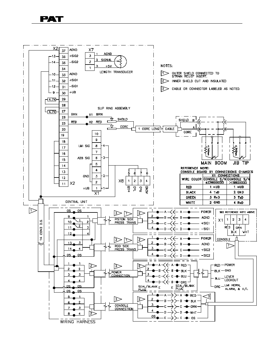
2. DRAWING 1, SYSTEM ELECTRICAL DIAGRAM
DS50 TROUBLESHOOTING
031-300-190-030 REVISION E 12/08/00
3 of 41
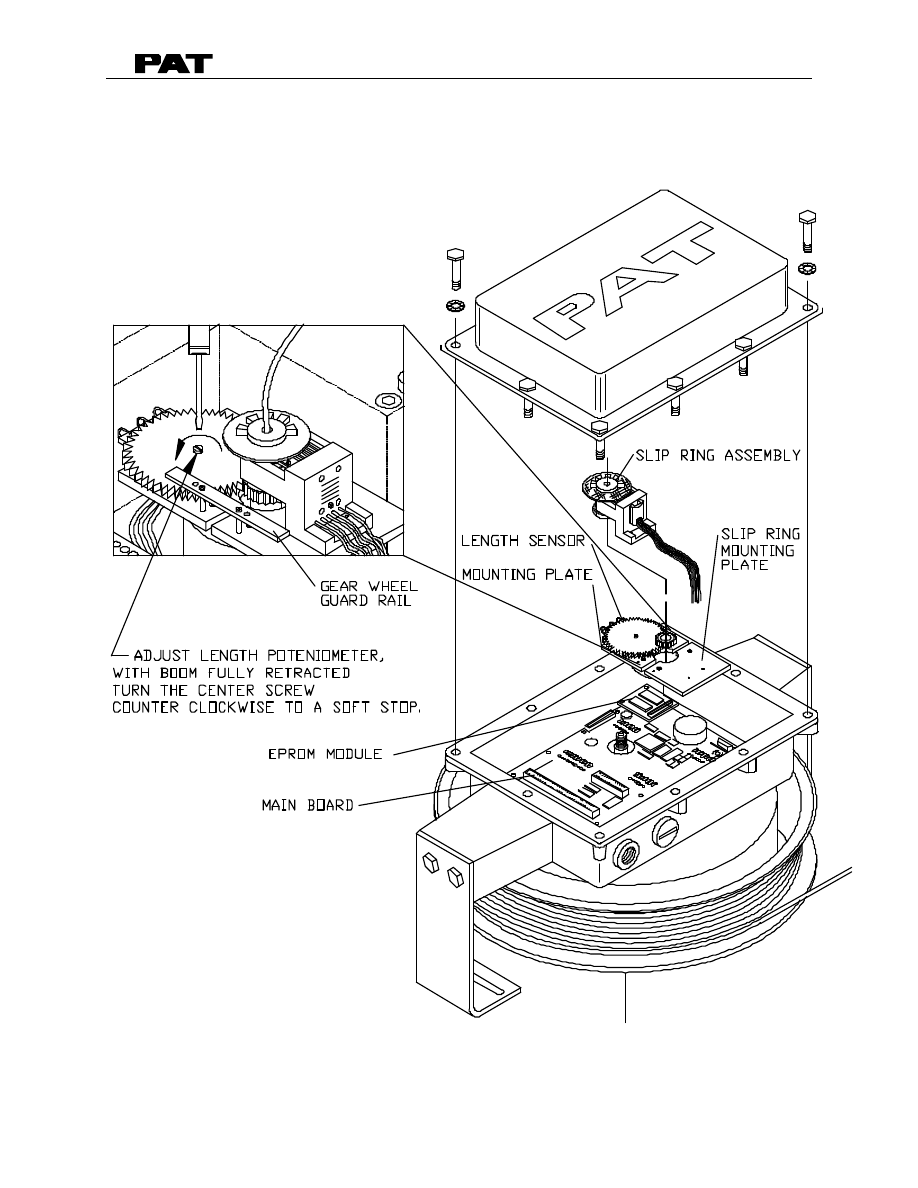
2. DRAWING 2, EXPLODED VIEW OF CABLE REEL AND
MECHANICAL ADJUSTMENT OF LENGTH SENSOR
DS50 TROUBLESHOOTING
031-300-190-030 REVISION E 12/08/00
4 of 41
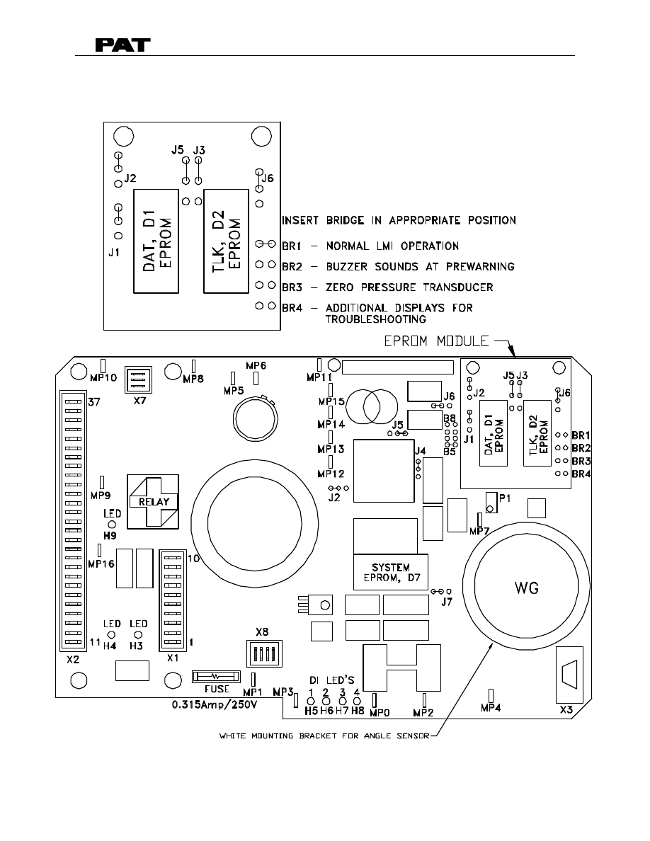
2. DRAWING 3, MAIN BOARD DS50
Note:
Bridge 5 on the main board must be installed if the white mounting bracket is
installed between main board and angle sensor.

DS50 TROUBLESHOOTING
031-300-190-030 REVISION E 12/08/00
5 of 41
DS 50 MAIN BOARD CONNECTION AND TERMINAL DEFINITIONS
X1/X2 (fast-on plug)
1
System supply (10 - 28V)
2
System supply (10 - 28V)
3
System ground
4
System ground
5
Relay middle contact
6
Relay work contact
7
Relay off position contact
8
Jumper UEL / HES
9
Jumper over load relay
10
Jumper hoist limit switch relay
11
Periphery supply (10 - 28V)
12
Digital input_1
13
Digital input_1
14
Digital input_2
15
Digital input_2
16
Digital input_3
17
Digital input_3
18
Digital input_4
19
Digital input_4
20
Periphery ground
21
Lamp driver_1
22
Lamp driver_1
23
Lamp driver_2
24
Lamp driver_2
25
Hoist limit switch signal
26
Hoist limit switch ground
27
Supply voltage potentiometric sensor
28
2
ND
angle sensor signal channel (analog reeving switch w/
MANITOWOC BOOM TRUCKS, INC. consoles)
29
Analog ground
30
Supply voltage passive DMS (9±0.45 VDC)
31
- return signal DMS
32
+ return signal DMS
33
Analog ground
34
Supply voltage passive DMS (9±0.45 VDC)
35
- return signal DMS
36
+ return signal DMS
37
analog ground

DS50 TROUBLESHOOTING
031-300-190-030 REVISION E 12/08/00
6 of 41
X3 (DBM 9pin) RS232 interface for (hand-) terminal
X4 digital angle sensor
X7 (screw snap-on terminal) length sensor
1
supply voltage potentiometric sensor
2
length sensor signal
3
analog ground
X8 (screw snap-on terminal) DS50 console interface
1
periphery supply (10 - 28V)
2
transmit data
3
receive data
4
periphery ground
Main Board Measuring Points
MPO
0V
module ground
MP1
+10 ... 28V
module supply
MP2
+9V ±0.45V
sensor supply
MP3
+5V ±0.25V
sensor supply
MP4
U
TTL
supply for hand terminal
MP5
U
GEB
/2
AN3 / angle sensor
MP6
U
GEB
/2
AN2 / length sensor
MP7
0 ... U
TTL
voltage controlled current output (U
TIL
=1mA)
MP8
U
TTL
/2
AN11
MP9
U
TTL
sensor supply
MP10
U
DMS
/2
symmetric voltage for de-coupling
MP11
U
ANAL
DMS – supply voltage
MP12
0V...5V
AN0
MP13
0V...5V
AN1
MP14
U
DMS
/3
AN9
MP15
2.74V+U
D
AN8 / temperature voltage
MP16
A2B signal
DS50 TROUBLESHOOTING
031-300-190-030 REVISION E 12/08/00
7 of 41
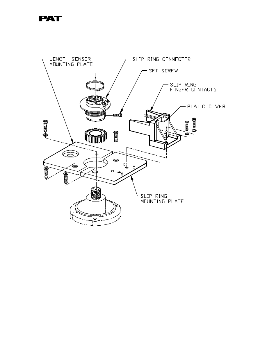
2. DRAWING 4, SLIP RING ASSEMBLY

DS50 TROUBLESHOOTING
031-300-190-030 REVISION E 12/08/00
8 of 41
3. TROUBLESHOOTING USING THE CONSOLE
The console will help you to find and correct system errors and problems. Troubleshooting
begins with the console display. The following table lists the screens available for
troubleshooting. These screens are available to check or verify operation but not needed
for normal operation. To display the troubleshooting screens, move the jumper from BR1
(Normal LMI Operation) to BR4 (Additional Displays for Troubleshooting) on the EPROM
module. Refer to Section 2 - Drawing 3. Main Board.
Table 1. Console displayed information
Display Position
Displayed Value XXXX
*0:
error code
1:
main boom length
2:
main boom angle
3:
Radius
4:
Utilization
5:
tip height
6:
rated load
7:
actual load
8:
actual moment
•
9:
pressure piston side [Bar]
•
0:
pressure rod side [Bar]
•
L:
voltage boom length [mv] (min 500 to max 2800)
•
P:
voltage pressure piston side [mv] (550 @ 0psi)
•
r:
voltage pressure rod side [mv] (550 @ 0psi)
•
o:
voltage angle sensor [mv] (2050
≅
55
°
/ 4500=0
°
to 500=90
°
)
•
U:
reference voltage + 5V [mv]
•
- Only displayed if jumper BR4 is installed on EPROM module attached to main board.
* - Only displayed if error is present.
If an error code is present, use the following error code table to determine the type, cause,
and remedy for the error. This will lead you to a specific section in this manual.
If no error code is displayed, troubleshoot the system by using the basic flowchart provided
in Section 4.

DS50 TROUBLESHOOTING
031-300-190-030 REVISION E 12/08/00
9 of 41
TABLE 2. ERROR CODE LIST
Error Code
Error
Cause
Remedy
Overload
•
cutoff due to overload
•
reduce load moment
prewarning
A2B switch is
activated
•
A2B switch activated,
broken length cable,
short in wring
•
lower the hook block
Refer to Section 6
E01
Fallen below
minimum radius
range or angle
range exceeded
•
fallen below the
minimum radius or gone
past the maximum angle
specified in the
respective load chart
due to luffing up the
boom too far
•
boom down to a radius
or angle specified in the
load chart
E02
Radius range
exceeded or fallen
below angle range
•
gone past the maximum
radius or fallen below
the minimum angle
specified in the
respective load chart
due to luffing up the
boom too far
•
boom up to a radius or
angle specified in the
load chart
E04
Operating mode
not available
•
A non existing operating
mode has been
selected
•
Set the correct
operating mode for the
operating state in
question

DS50 TROUBLESHOOTING
031-300-190-030 REVISION E 12/08/00
10 of 41
ERROR CODE LIST - continued
Error Code
Error
Cause
Elimination
E05
Forbidden length
range of the main
boom
•
Boom has been
extended too far or not
enough, e.g. if operation
is only admitted up to a
certain boom length or
for load charts of jibs
with the boom having to
be extended to a certain
length.
•
The length sensor
adjustment was
modified, e.g. rope slid
off the length sensor
reel.
•
Clutch between length
sensor pot and drive is
defective
•
Failure of the +5V-
supply for the analog
part of the LMI-analog
board.
•
Length potentiometer
defective.
•
Retract or extend boom
to the correct length.
•
Retract the boom.
Check the pre-stress of
the cable reel (refer to
Drawing 2)
•
Completely replace the
clutch with the drive
wheel and adjust length
sensor pot (refer to
Drawing 2)
•
Check +5V-voltage,
MP3 and GND.
exchange LMI board.
•
Replace length
potentiometer. (refer to
Section 13 length
sensor replacement)

DS50 TROUBLESHOOTING
031-300-190-030 REVISION E 12/08/00
11 of 41
ERROR CODE LIST - continued
Error Code
Error
Cause
Elimination
E07
Faulty
acknowledgment
by the overload
relay of the LMI
board.
•
Overload relay defective
•
LMI board defective
•
Replace LMI board
E08
No
acknowledgement
of the anti-two-
block switch relay
on main board.
•
Overload relay defective
main board defective
•
Replace LMI board
E11
Fallen below limit
for the measuring
channel "Length
telescopic boom".
•
Length sensor pot
defective.
•
Electronic board in the
measuring channel
defective.
•
Replace length sensor
potentiometer.
•
Replace LMI board.
E12
Fallen below the
lower limit value in
the measuring
channel "pressure
piston side"
•
Cable between the
central unit and pressure
transducers defective or
water inside the plugs
•
Check cable as well as
plugs, replace, if need
be.
•
Pressure transducer is
defective.
•
Replace pressure
transducer
•
Electronic component in
the measuring channel
is defective.
•
Replace LMI main board
or processor board.
E13
Fallen below lower
limit value in the
measuring channel
"pressure rod
side"
•
refer to E12
•
refer to E12

DS50 TROUBLESHOOTING
031-300-190-030 REVISION E 12/08/00
12 of 41
ERROR CODE LIST - continued
Error Code
Error
Cause
Elimination
E15
Fallen below lower
limit value for the
measuring channel
"angle main
boom".
•
Angle sensor defective.
•
Electronic part in the
measuring channel
defective.
•
Replace angle sensor.
•
Replace LMI board.
E19
Reference and/or
supply voltage
defective
•
The supply voltage is
incorrect for one of the
sensors (DAV, LWG)
•
Check the voltages on
the LMI main board MP0
(AGND) to MP1, MP2, &
MP3 (supply voltages).
Refer to Section 2.
Check sensors, plugs
and cables, replace, if
need be.
•
Electronic component is
defective
•
Replace LMI main board
E21
Upper limit value
for measuring
channel "length
telescopic boom"
exceeded.
•
Length sensor pot
defective.
•
Electronic part in the
measuring channel
defective.
•
Replace length sensor
potentiometer.
•
Replace LMI board.
E22
Upper limit value in
measuring channel
"pressure piston
side" has been
exceeded
•
refer to E12
•
refer to E12
E23
Upper limit value in
measuring channel
"pressure rod
side" has been
exceeded.
•
refer to E12
•
refer to E12
E25
Upper limit value in
measuring channel
"angle main boom"
exceeded
•
Angle sensor defective.
•
Electronic part in the
measuring channel
defective.
•
Replace angle sensor.
•
Replace LMI board.
E31
Error in the system
program
•
The system program
PROM is defective.
•
Replace system
program EPROM
(EPROM D7) Refer to
Section 16.

DS50 TROUBLESHOOTING
031-300-190-030 REVISION E 12/08/00
13 of 41
ERROR CODE LIST - continued
Error Code
Error
Cause
Elimination
E38
System program
and data EPROM
do not match.
•
The system program in
the LMI does not match
to the programming in
the data EPROM
•
Replace the system
program EPROM (D7)
or the data EPROM
(D1)
Refer to Section 16.
E39
System program
and TLK EPROM
do not match
•
The system program in
the LMI and the
programming in the TLK
EPROM do not match.
•
Replace system
program EPROM (D7)
or TLK EPROM (D2).
Refer to Section 16.
E41
Error in the internal
write/read memory
(RAM) of the
computer
component
80C537
•
Computer component
80C537 defective
•
CPU module defective
•
Processor board
defective.
•
Replace computer
component 80C537.
•
Replace CPU module.
•
Replace processor
board with CPU module.
E42
Error in the
external write/read
memory, 1st part
(RAM)
•
Write/read memory
(CMOS RAM) or
processor board
defective.
•
Replace processor
board with CPU module.
E43
Error in the
external write/read
memory, 2nd part
(RAM)
•
refer to E42
•
refer to E42
E45
Redundancy error
in the A/D
conversion
•
The A/D converter on
the processing board
and the redundant A/D
converter in the CPU
80C537 provide
different results.
•
Replace processor
board.
E46
Error in the A/D
converter uPD
7004 of the
processor board.
•
No acknowledgment of
the A/D converter uPD
7004
•
Replace processor
board.

DS50 TROUBLESHOOTING
031-300-190-030 REVISION E 12/08/00
14 of 41
ERROR CODE LIST - continued
Error Code
Error
Cause
Elimination
E47
Error in the
monitored write/
read memory.
The CRC
verification of the
monitored
write/read memory
provides an
incoherent result
•
The CRC sign of the
monitored write/read
memory is wrong
•
The buffer battery is
discharged (< 2V at
1kOhm).
•
Processor board
defective.
•
Restart the LMI
•
Replace buffer battery
on the LMI main board
•
Replace processor
board.
E48
Cyclic RAM test:
error in the internal
write/read memory
(RAM) of the
computer
component
80C537
•
Computer component
80C537 defective
•
CPU module defective
•
Processor board
defective.
•
Replace computer
component 80C537.
•
Replace CPU module
•
Replace processor
board with CPU module.
E51
Error in the crane
data EPROM or
EEPROM.
•
No valid data in the
crane data EEPROM.
•
Memory module wrongly
bridged.
•
Crane data EPROM
defective
•
Load crane data
EEPROM containing
valid data.
•
Bridge memory module
acc. to memory type
•
Replace crane data
EPROM (D1) Refer to
Section 16.
E52
Error in load chart
PROM.
•
Memory module wrongly
bridged.
•
Load chart EPROM
defective.
•
Bridge memory module
acc. to memory type.
•
Replace load chart
EPROM (D2) Refer to
Section 16.
E56
Error in crane data
EEPROM.
•
Memory module wrongly
bridged.
•
Crane data EEPROM
defective
•
Bridge memory module
acc. to memory type
•
Replace crane data
EEPROM (D1) Refer to
Section 16.

DS50 TROUBLESHOOTING
031-300-190-030 REVISION E 12/08/00
15 of 41
ERROR CODE LIST - continued
Error Code
Error
Cause
Elimination
E57
Error in serial
crane data
EEPROM.
•
Serial crane data
EEPROM does not
contain valid data.
•
Memory module
defective
•
Write data on the serial
crane data EEPROM
(by means of test
program or on-line
function), then restart the
LMI
•
Replace memory
module.
E58
Error in the serial
analog data
EEPROM.
•
No valid data in the
serial analog data
EEPROM.
•
LMI main board
defective.
•
Write data on the serial
analog data EEPROM
by means of the test
program, then, restart
the LMI
•
Replace LMI main
board.
E80
Error in piston-side
pressure
transducer
Or
zero adjustment
setting is out of
range
•
Pressure offset value out
of specification
•
Check zero point of
pressure transducer
(Ensure no residual
pressure at transducer
during zeroing
procedure).
•
Initialize EPROM
Module board (contact
your service
representative)
•
Pressure transducer
defective, replace and
zero transducer.
E81
Error in rod-side
pressure
transducer
•
refer to E80
•
refer to E80
E84
Wrong rigging
condition.
•
The selected rigging
condition is not
contained in the data
EPROM.
•
Select another rigging
condition
•
Check the programming
in the data EPROM.
E85
Error in the radius
determination
•
The computed radius is
too small (negative
deflection)
•
Check the programming
in the data EPROM.

DS50 TROUBLESHOOTING
031-300-190-030 REVISION E 12/08/00
16 of 41
ERROR CODE LIST - continued
Error Code
Error
Cause
Elimination
E91
No data trans-
mission form the
console to the
central unit
•
24 V supply of the
console is interrupted
•
Check 24 V at terminal
X1 of the console
electronics
•
Interruption or accidental
ground in the line
between console
electronics and central
unit
•
Check the connection
console electronics -
central unit. In case of an
accidental ground, the
transmitter module of the
console electronics
might be damaged.
Therefore, replaces the
console electronics.
•
Transmitter/receiver
module is defective
•
Exchange console
electronics or LMI main
board respectively
E92
Error in the data
transmission from
console to central
unit
•
Loose connection in the
line between console
electronics and central
unit
•
Transmitter/receiver
module is defective
•
Check the connection
between console
electronics and central
unit
•
Exchange console
electronics or LMI main
board respectively.
E93
Error in the data
transmission from
the central unit to
the console
•
refer to E92
•
refer to E92

DS50 TROUBLESHOOTING
031-300-190-030 REVISION E 12/08/00
17 of 41
ERROR CODE LIST - continued
Error Code
Error
Cause
Elimination
E94
No data trans-
mission from the
central unit to the
console
•
Interruption or accidental
ground in the line central
unit - console
•
Check line to the
console (in case of
accidental ground,
replace console
electronics, too).
•
5 V supply of the
computer in the central
unit is missing
•
Check connection to the
power unit
•
5 V supply is too low
•
Exchange the LMI main
board
•
Transmitter/receiver
module is defective
•
Replace console
electronics or LMI main
board
•
Computer module is
defective
•
Replace processor
board.
•
Electro-magnetic
interferences (e.g. when
switching contacts or
valves)
•
Eliminate the source of
interferences by inverse
diodes or varistors.
E95
Error in the
console EPROM
•
The console EPROM is
defective.
•
Replace the console
EPROM
E96
Error in the internal
RAM of the
console.
•
The CPU of the console
is defective.
•
The console main board
is defective.
•
Replace the CPU of the
console
•
Replace the console
main board.
DS50 TROUBLESHOOTING
031-300-190-030 REVISION E 12/08/00
18 of 41
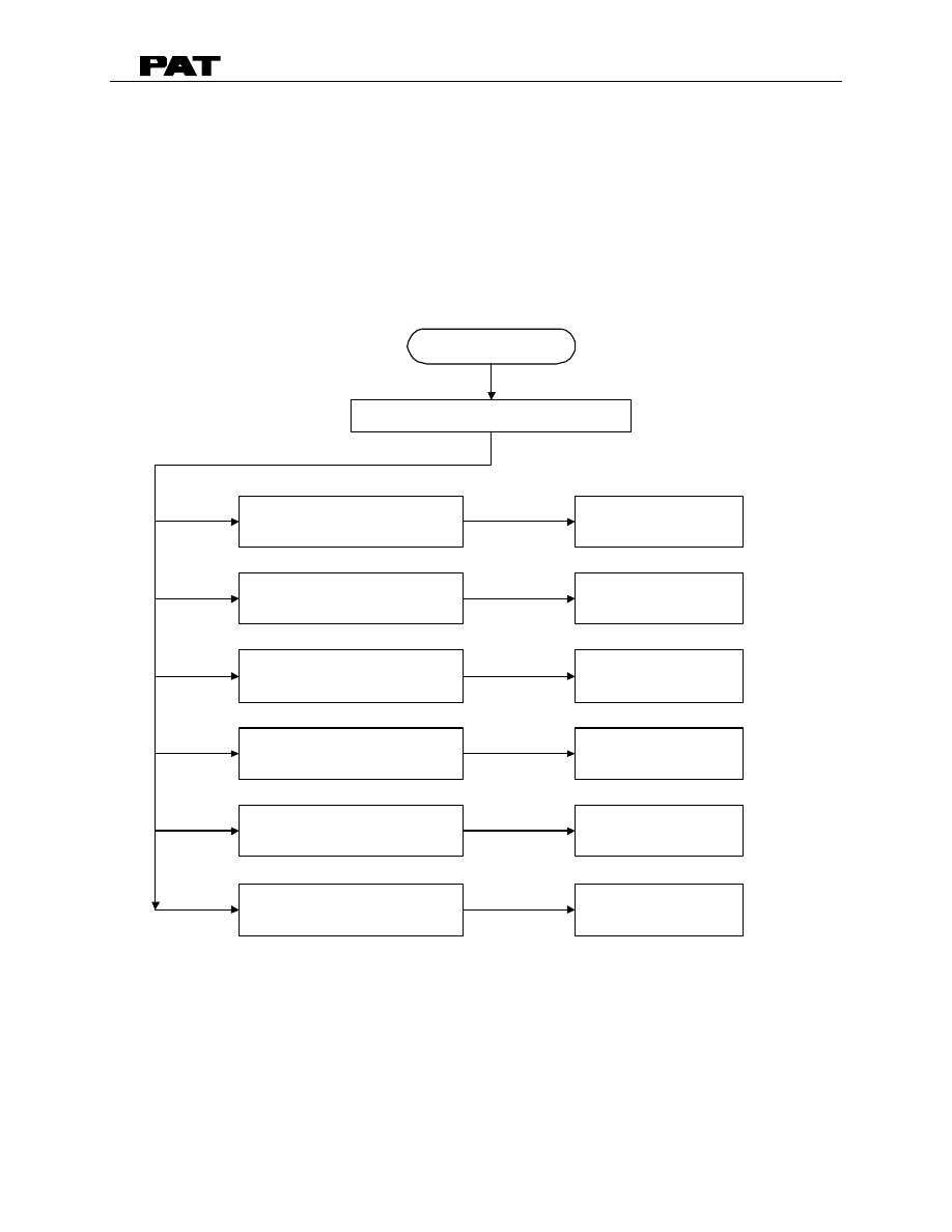
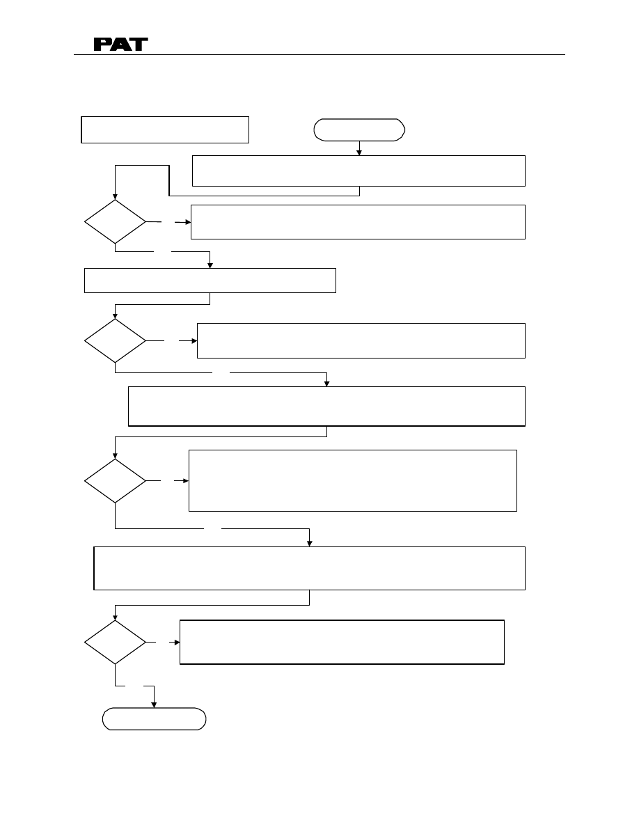
4. TROUBLESHOOTING FLOW CHART
This section explains how to handle a problem that may arise with the DS50, PAT Load
Moment Indicator System. The procedures are easy to follow and are given in flowcharts on
the following pages. Start with the general flowchart below, which will guide you to one of
the detailed flowcharts shown in Sections 4 through 10. This section also contains the
necessary drawings needed for troubleshooting.
What’s Wrong?
START
No display
Anti-Two Block Problem
Length Reading Problem
Angle Reading Problem
Load Reading Problem
Go to Section 5
Go to Section 6
Go to Section 7
Go to Section 8
Go to Section 9
Bad Data Transfer Between
Console and Central Unit.
Go to Section 10
The drawings in Section 2 are provided as reference material that will be used in the
troubleshooting flow charts. Use the drawings in conjunction with the flow charts to help
understand the operation of the DS50 system.
DS50 TROUBLESHOOTING
031-300-190-030 REVISION E 12/08/00
19 of 41
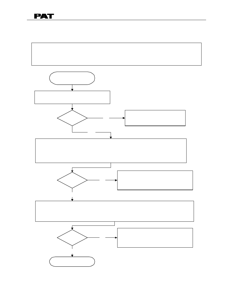
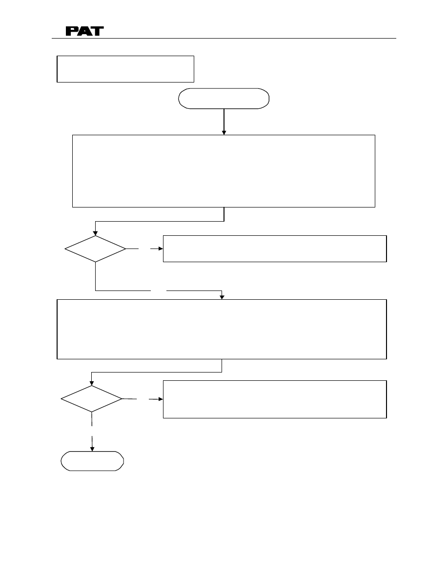
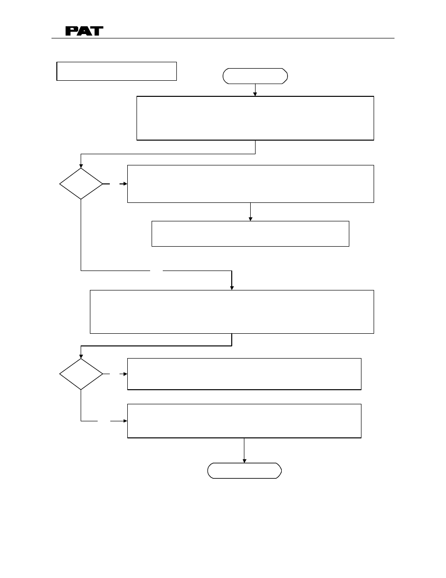
5. NO DISPLAY
PROBLEM: Blank console display with no warning light shown.
All crane movments have been stopped.
Measure crane voltage on connection board
between X1:1 (+12/24V) and X1:3 (ground).
Refer to Drawing 1, DS50 Cable Reel, Section 2 - Drawings.
Check fuses in CU and Console.
Correct?
Replace fuses.
0.315AMP/250V For Console
and Central Unit
Measure crane voltage on connection board
between X8:1 (+12/24V) and X8:4 (ground).
Refer to Drawing 1, DS50 Cable Reel, Section 2 - Drawings.
Correct?
Defect on main board. Replace main
board using replacement procedure
Section 11.
Next Page
Correct?
Start
No
Yes
Check crane power supply for faulty
crane electric or if supply is too low.
No
No
Yes
Yes
DS50 TROUBLESHOOTING
031-300-190-030 REVISION E 12/08/00
20 of 41
Continued from previous page
PREVIOUS PAGE
Measure voltage at Console between X1:1 (+12V) and X1:4 (ground).
Refer to Drawing 2, DS50 System, Section 2 - Drawings.
Correct?
Faulty wiring or connections between console and
central unit. Check wiring connections.
Replace console board.
END
No
Yes
DS50 TROUBLESHOOTING
031-300-190-030 REVISION E 12/08/00
21 of 41
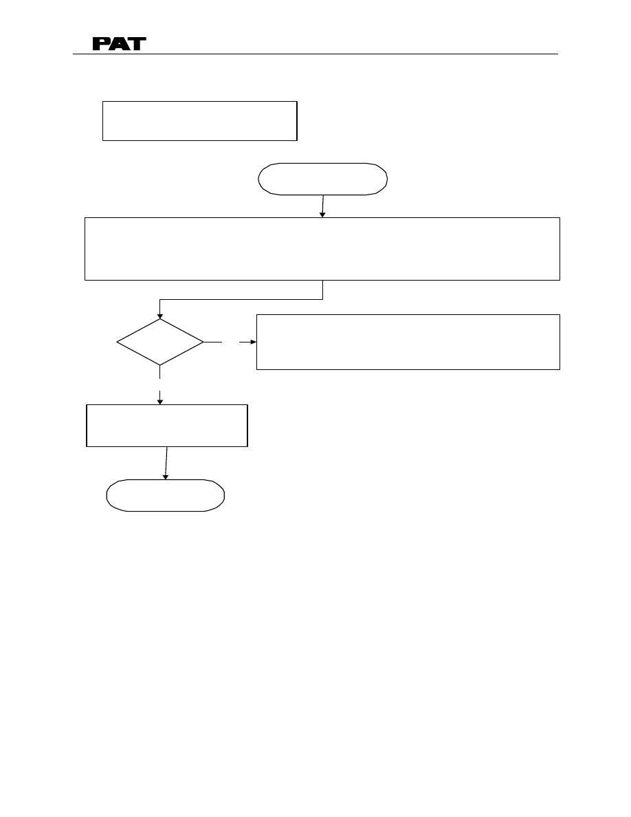
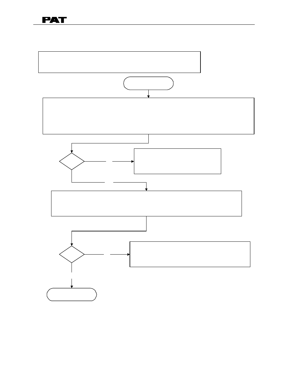
6. ANTI TWO BLOCK PROBLEM
Check weight position. Refer to Operator's Handbook 031-300-190-014 Section 4.1 for
switch weight positions for the main boom and extension.
PROBLEM: Function of Anti-Two-Block System is faulty.
START
Check to see whether or not crane is in two-block condition.
Correct?
Lower hook down into safe position
Position the weight properly.
Check the A2B switch resistance at the boom tip junction box.
With power off, remove length cable connection to the boom tip junction box.
Measure A2B signal in the box receptacle connection A & B.
With the switch weight in position the ohm meter reads 4.7K ohms.
Reconnect length cable to junction box.
Refer to Drawing 1 , DS50 Cable Reel, Section 2 - Drawings.
Replace Anti-Two-Block switch.
Next Page
Correct?
Correct?
No
Yes
No
No
Yes
Yes
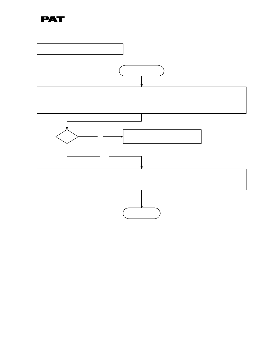
DS50 TROUBLESHOOTING
031-300-190-030 REVISION E 12/08/00
22 of 41
Fault in slip ring. Replace slip ring.
Refer to Section 11 - steps 4, 6, 7, 8, 12, 13, 15.
Refer to Drawing 5, Slip RIng Assembly, Section 2.
Continued from previous page.
PREVIOUS PAGE
With power off, measure the A2B signal at the slip ring in the cable reel.
Locate the brown and red wires at the top of the slip ring.
With the switch weight in position the ohm meter reads 4.7K ohms.
Refer to Drawing 1 , DS50 Cable Reel, Section 2 - Drawings.
Correct?
Fault in length cable. Replace length cable.
Refer to Section 12.
With power off, measure the A2B singal at the X2:25 and X2:26 on main board.
With the switch weight in position the ohm meter reads 4.7K ohms.
Refer to Drawing 1 , DS50 Cable Reel, Section 2 - Drawings.
Correct?
Next Page
No
Yes
No
Yes
DS50 TROUBLESHOOTING
031-300-190-030 REVISION E 12/08/00
23 of 41
Continued from previous page.
PREVIOUS PAGE
With power on and the switch weight in position,
check LED H4 and H9 are off.
Refer to Drawing 4 , DS50 Cable Reel, Section 2 - Drawings..
Correct?
Faulty main board. Replace Main Board.
Refer to Section 11.
End
No
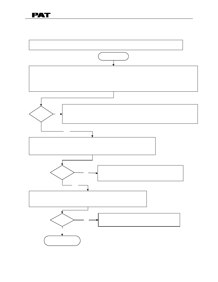
DS50 TROUBLESHOOTING
031-300-190-030 REVISION E 12/08/00
24 of 41
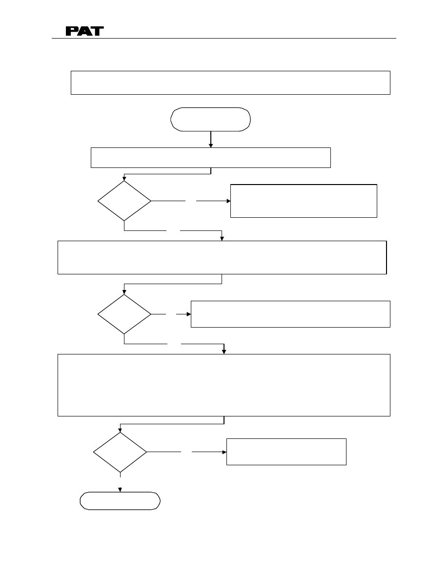
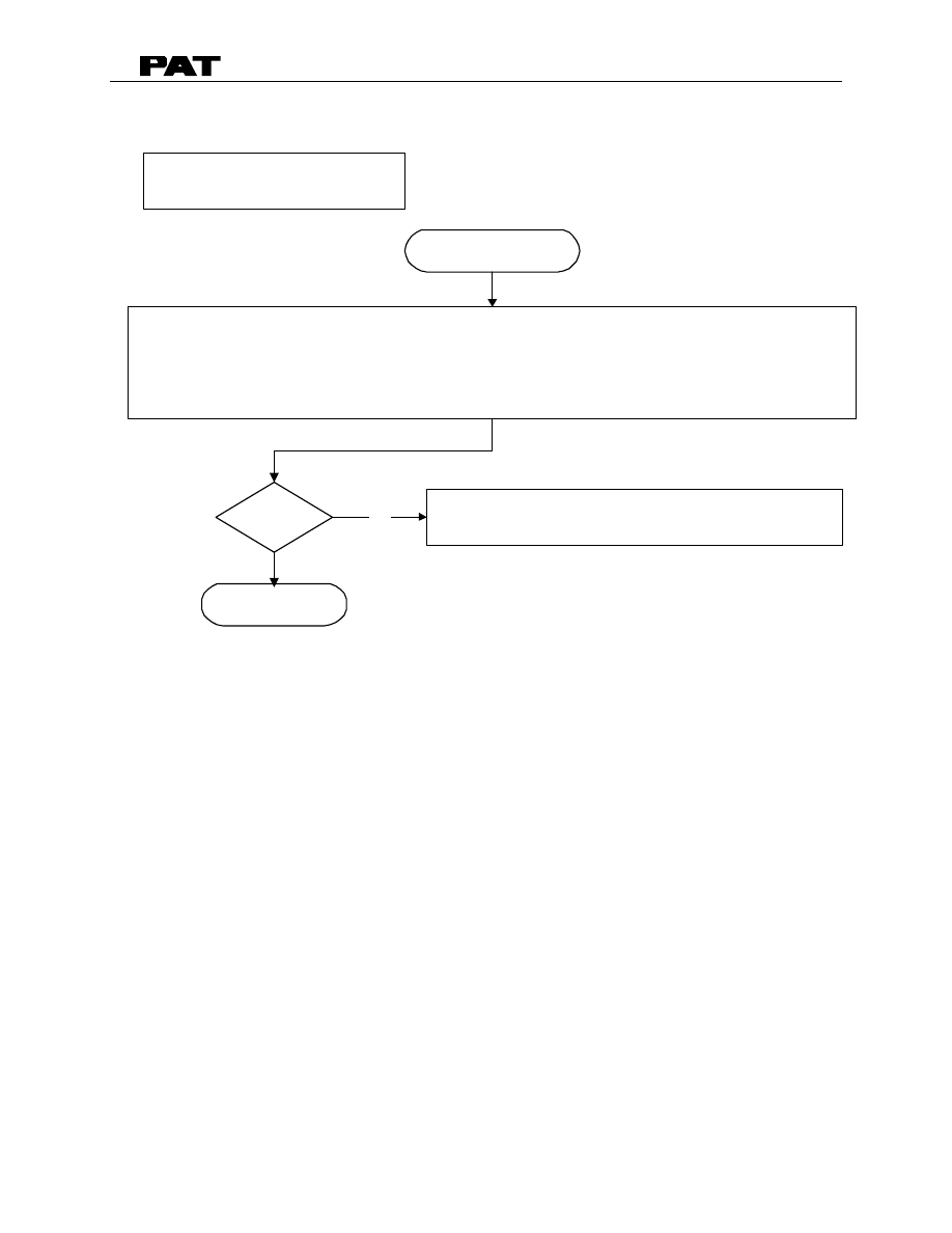
7. LENGTH READING PROBLEM
Inspect clutch in big gear wheel of length transducer. Extend and retract boom to
ensure that clutch is not sipping on potentiometer axle.
Refer to Drawing 3, Cable Reel , Section 2 - Drawings.
Replace length potentiometer assembly.
Refer to Section 11 - steps 4, 6, 7, 8, 12, 13, 15 (length potentiometer only).
Refer to Drawing 3, Length Sensor Adjustment Section 2 - Drawings .
START
PROBLEM: Displayed Length Incorrect. Actual measured length is different from displayed length.
Replace the gear wheel, clean potentiometer
axle. Reset length potentiometer.
Check power supply to length transducer on main board.,
X7:1 (+5V) and X7:3(ground)
Refer to Drawing 4, DS50 Main Board, Section 2 - Drawings.
Main board defective. Replace main board and
reset pressure channel. Refer to Section 11
END
Correct?
Correct?
Correct?
No
No
Yes
No
Yes
Check mechanical adjustment of length potentiometer in cable reel.
Refer to Drawing 3, Cable Reel, Section 2- Drawings.
Check length signal voltage on mainboard at MP6 (length) and MP0 (GND): +0.5 volts.
Refer to Drawing 4, DS50 Main Board, Section 2 - Drawings.
Yes
DS50 TROUBLESHOOTING
031-300-190-030 REVISION E 12/08/00
25 of 41
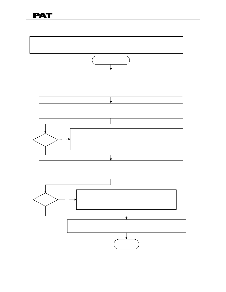
8. ANGLE READING PROBLEM
Setup the angle to met the specification.
Refer to Section 14. Angle Sensor Setup/Adjustment Procedures.
START
PROBLEM: Displayed Angle Incorrect. Actual measured angle is different from displayed angle.
Note: Bride 5 on the main board must be installed if the white mounting bracket is installed
between main board and angle sensor.
Main board defective. Replace main board and
reset pressure channel.
Refer to Section 11, Main Board Replacement.
END
Correct?
Use a calibrated inclinometer to measure the actual main boom angle and compare with
displayed angle on console. Compare the boom angle at 30°, 60°, and 80° ±2°.
Is the displayed angle greater than ±0.5° of the actual boom angle.
Refer to Checking Specification in Section 14. Angle Sensor Setup/Adjustment Procedures.
No
Check the voltage between MP0 (ground) and MP3 (sensor supply voltage).
MP3 (+5V ±0.25V).
Refer to Drawing 4, Main Board & Connections. Section 2.
No
Check the voltage on the main board between MP0 (ground) and MP1 (system voltage).
Refer to Drawing 4, Main Board & Connections. Section 2.
Check system power supply voltage in Cable Reel
between X2:1 (+UB) and X2:3(gnd)
If system voltage is below 10V, check crane power supply.
Refer to Drawing 1 or 2. Section 2.
Correct?
Yes
No
Yes
DS50 TROUBLESHOOTING
031-300-190-030 REVISION E 12/08/00
26 of 41
9. LOAD READING PROBLEM
Measure radius and check with the displayed radius.
Check selected operating mode to ensure it matches the current crane
configurations.
PROBLEM: Load reading incorrect.
START
Select the correct operating mode for the current crane configurations.
See Section 7. Length Reading Problem.
See Section 8. Angle Reading Problem.
Check the voltage between MP0 (ground) and MP1 (system voltage).
Refer to Drawing 4, Main Board & Connections. Section 2.
Next Page
Correct?
No
Yes
Correct?
No
Yes
Correct?
No
Check system power supply voltage in Cable Reel
between X2:1 (+UB) and X2:3(gnd)
If system voltage is below 10V, check crane power supply.
Refer to Drawing 1 or 2. Section 2.
Check the voltage on the main board between MP0 (ground) and MP2 (sensor supply voltage).
MP2 (+9V ±0.45V).
Refer to Drawing 4, Main Board & Connections. Section 2.
Yes
Correct?
Sensor supply voltage incorrect. Replace Main Board.
Refer to Section 11, Main Board Replacement.
No
Yes
DS50 TROUBLESHOOTING
031-300-190-030 REVISION E 12/08/00
27 of 41
Check pressure transducer cable assemblies connector between:
Pin A (sensor supply voltages) and Pin B (ground) = +9V ±0.45V
Refer to Drawing 2, System Electric. Section 2.
Continued from previous page
Previous Page
END
Transducers should be good. Perform zero adjustment procedure.
See Section 15. Pressure Transducer Zero Adjustment and
Replacement Procedure.
Correct?
No
Check wiring connections and continuity from cable reel to pressure transducer.
Refer to Drawing 2, System Electric. Section 2.
Check pressure transducer signal in cable reel between:
Transducer A X1:31 (- signal) and X1:32 (+ signal) = 1.0 to 1.5 mV
Transducer B X1:35 (- signal) and X1:36 (+ signal) = 1.0 to 1.5mV
Refer to Drawing 2, System Electric. Section 2.
Yes
Correct?
Yes
Replace pressure transducer.
Refer to Section 15, Pressure Transducer Zero Adjustment and
Replacement Procedure.
No
Replace defective connector and/or cable assembly.
DS50 TROUBLESHOOTING
031-300-190-030 REVISION E 12/08/00
28 of 41
10. BAD DATA TRANSFER BETWEEN CONSOLE & CENTRAL UNIT
Check supply crane voltage for console in central unit at X1:1 and X1:3 (12V). Make sure
external and internal power supply is correct.
Refer to Drawing 1, DS50 Cable Reel, in Section 2 - Drawings.
PROBLEM: Error Code “E91/E92" No data transfer to and from console.
Make sure that Data EPROM is plugged into eprom module socket D1, TLK EPROM is plugged
into eprom module socket D2, and System EPROM is plugged into main board socket D7.
Check that EPROMs are inserted with notch on EPROM to matching notch on socket.
Refer to Drawing 4, Main Board, Section 1- Drawings
Refer to Section 16 for Eprom Replacement instructions.
Place EPROM in correct socket, and
ensure it is orientated correctly.
Refer to Section 16
Replace main board and reset pressure channel.
Refer to Section 11.
Next Page
Correct?
Correct?
START
No
Yes
No
Yes
DS50 TROUBLESHOOTING
031-300-190-030 REVISION E 12/08/00
29 of 41
Continued from previous page
Check power supply to console between console terminal X1:1 and X1:4 (+12/24v) and
Check the continuity of wires between Central Unit X8:1 - 4 and Console X1:1 - 4.
Refer to Drawing 1, DS50 Cable Reel, Section 2- Drawings.
Faulty wiring in cable from central unit to
console. Replace cable.
Defective electrical components on main board. Replace main board and reset pressure channels.
Refer to Section 11, Main Board Replacement.
END
Correct?
PREVIOUS PAGE
No
YES

DS50 TROUBLESHOOTING
031-300-190-030 REVISION E 12/08/00
30 of 41
11. MAIN BOARD REPLACEMENT PROCEDURE
This section explains the replacement of the main board in the event of defect. Only when
the adjustment and tests have indicated failed components, should you proceed with this
section. Refer to Drawing 2, Section 2, to help locate parts.
1. Retract the boom fully. Refer to the manufacturer’s operator’s manual and familiarize
yourself with its operation and the LMI bypass. Lower the boom to gain access to the
DS 50 system.
2. Switch crane power off.
1 Remove the cable reel cover face by loosening all 10 screws. The screws should
remain secured to the lid.
CAUTION: Use care and minimal force when removing the wire ends and terminals
from the connections.
1. Remove all connections located at X-1, X-2, X-7 and X-8. Check the wires to ensure
they are numbered. This will allow an easier installation.
2. Remove the two screws that secure the EPROM module and remove it.
3. Remove the two screws that secure the gear wheel guardrail.
4. Remove the 4 screws holding the slip ring/length sensor mounting plates.
5. Remove slip ring and length sensor assemblies.
CAUTION:
Use care while removing the screws because a slip of your screw
driver can cause serious damage to the surface of the board and may even cut
critical electronic traces.
6. Locate the 8 Philips screws that secure the main board to the cable reel housing and
carefully remove them.
7. Install new main board and replace the 8 Philips screws
8. Reconnect wires as labeled in Step 4.
Set up angle by using procedure in Section 15. Refer to Section 8 if angle is incorrect.
9. Replace the length sensor and slip ring assemblies.
10. Zero the length sensor and check actual length equals displayed length, refer to
Drawing 2 - Section 2. Refer to Section 7 if length is incorrect.
11. Zero the pressure transducers. Refer to Section 15.
12. Replace the cable reel cover face and tighten the 10 screws.

DS50 TROUBLESHOOTING
031-300-190-030 REVISION E 12/08/00
31 of 41
12. LENGTH CABLE REPLACEMENT PROCEDURE
Replace length cable using the following procedure:
1. Retract the boom fully. Refer to the manufactures operators manual and familiarize
yourself with its operation and the LMI bypass. Lower the boom to gain access to the
DS 50 system.
2. Switch crane power off.
3. Disconnect damaged length cable from junction box at the boom nose.
4. Remove the cable reel cover face by loosening all 10 screws. The screws should
remain secured to the lid.
CAUTION: Use care and minimal force when removing the wire ends and terminals
from the connections.
5. Remove all connections located at X1, X2, X7, and X8. Check the wires to ensure they
are numbered, this will allow an easier installation.
6. Open the strain relief for the 10 and 7 conductor cables and pull the cables out of the
cable reel.
7. Remove cable reel from mounting brackets.
8. Remove all conductors from X1 and X2 of the slip ring terminal. Refer to Drawing 1 and
2 in Section 2.
9. Cut old cable at the backside of the cable drum and remove cable.
10. On the backside of the cable reel, open the strain relief attached to the axle in the
center of the drum. Pull existing length cable out of the cable reel.
11. Pull new length cable through the hole, pipe and strain relief and push it through the axle
of the reeling drum. Tighten strain relief to ensure sealing.
12. Reconnect the length cable to the slip ring terminal. Refer to Drawing 1 in Section 2.
13. Remount cable reel to the boom.
14. Turn reeling drum clockwise to spool the new cable neatly onto the drum.
15. Set preload on cable reel by turning the drum counter-clockwise 5 to 8 turns.
WARNING
The cable drum is under high tension. Do not let the length cable spool back without
supporting the cable and leading it back on the drum. Pay attention and watch that the
wraps do not pile up on one side. De-spooling of the length cable can cause damage to
the length sensor. Spooling the length cable without additional support may result in injury
or damage. Use caution and protection when working with the length cable under high
tension.

DS50 TROUBLESHOOTING
031-300-190-030 REVISION E 12/08/00
32 of 41
16. Anchor cable at boom point.
17. Connect the length cable into the boom tip junction box. Refer to Drawing 1 in Section
2.
18. Fully retracted boom and reset length potentiometer by turning potentiometer carefully
counter-clockwise until it stops. Refer to Drawing 2 in Section 2. Check displayed
length. Refer to Section 7 if length is incorrect.
19. Check the angle. Use a calibrated inclinometer to measure the main boom angle and
compare with displayed angle on console. Adjust the cable reel housing if necessary.
Loosen the mounting bolts holding the cable reel to the boom. One of the mounting
brackets is slotted which will allow the cable reel to be adjusted on the boom until the
displayed angle is equal to or 2 degrees less than the actual (measured) boom angle.
Refer to Section 8 if angle is incorrect.
20. Verify A2B operation. Refer to Operator’s Manual 031-300-190-014 Section 5.

DS50 TROUBLESHOOTING
031-300-190-030 REVISION E 12/08/00
33 of 41
13. LENGTH SENSOR REPLACEMENT PROCEDURE
This section explains the replacement of the length potentiometer in the event of defect.
Refer to Drawing 2 in Section 2.
CAUTION:
The length potentiometer is an electronic component and not designed to
withstand large forces or moments. Carefully adjust the potentiometer only when instructed
in this manual. Take special care when you approach the stops on either end.
1. Retract the boom fully. Refer to the manufacturer’s operator’s manual and familiarize
yourself with its operation and the LMI bypass. Lower the boom to gain access to the
DS 50 system. Switch crane power off.
2. Remove the cable reel cover face by loosening all 10 screws. The screws should
remain secured to the lid.
3. Remove wires # 1, 2, and 3 from the main board X7 terminal connections.
4. Remove length sensor assembly. Refer to Drawing 2 in Section 2.
5. Remove the two screws that secure the gear wheel guardrail.
6. Remove the gear wheel from the potentiometer axle by pulling it straight out with your
fingers.
7. Remove the 2 screws holding the mounting plate of the length sensor assembly.
8. Now remove the retainer nut at the center of the length potentiometer shaft.
9. Mount the new length potentiometer in the same location and position it the same as
the one you removed. Pay attention to the locking washer. The pin of the washer must
recess in the hole provided in the mounting bracket to avoid movement of the
potentiometer body during operation. Use caution when tightening the potentiometer
nut. Do not over- torque the nut.
10. Carefully slide the large white nylon gear wheel onto the potentiometer shaft.
11. Install the new length potentiometer assembly by securing the mounting plate with the 2
Phillips screws.
•
Check to ensure the gears mesh and are aligned.
•
Ensure that the grounding wire is also reconnected at the lower right mounting
screw.
12. Reconnect wires # 1, 2 and 3 to the corresponding X7 of main board. (Be sure that
wires are secured in a way that they cannot become caught in the gear wheel).
13. Fully retract boom and reset length potentiometer by turning potentiometer carefully
counter-clockwise until it stops. Refer to Drawing 2 in Section 2. Check displayed
length. Refer to Section 7 if length is incorrect.

DS50 TROUBLESHOOTING
031-300-190-030 REVISION E 12/08/00
34 of 41
14. ANGLE SENSOR SETUP/ADJUSTMENT PROCEDURE
The following procedure should be used to set the angle for the DS50 system.
Purpose:
The purpose for the DS50 angle setup procedure is to mechanically align the angle sensor
with the boom.
Procedure Summary:
To achieve the best accuracy in the machine’s typical working area, the displayed angle
needs to match the actual angle at or near 45
°
rather than at 0
°
. To match the displayed
and actual angle at 45
°
, the cable reel must be mechanically adjusted at 45
°
.however, the
physical location of the cable reel prevents this direct action. The procedure first matches
the displayed to the actual angle at 0
°
, then booms up to 45
°
to determine the difference
between the displayed and actual angle. The angle difference found is used to adjust the
cable reel angle at 0
°
where it is physically possible. The displayed and actual angles
match at 45
°
. After completing the setup procedure, check to ensure the displayed angle
meets the specification.
Equipment:
Calibrated inclinometer to determine actual boom angle.
Specification:
The angle is in tolerance when the displayed angle is within
±
0.5
°
of the actual boom angle
throughout the working range of the boom.
The responsibility for the safe crane operation shall remain with the crane
operator who shall ensure that all warnings and instructions supplied are fully
understood and observed.
NOTE: During the angle setup procedure, the boom should be fully retracted and have no
load on the hook block.
Setup Procedure:
1. Move the boom angle between -2 to 2 degrees using the inclinometer as reference to
actual angle.
2. Adjust the cable reel so the displayed boom angle matches the actual angle. Adjust the
cable reel by loosening the mounting bolts holding the cable reel to the boom. The
mounting brackets are slotted to allow for adjustment.

DS50 TROUBLESHOOTING
031-300-190-030 REVISION E 12/08/00
35 of 41
3. Move the boom angle between 43
°
to 47
°
using the inclinometer as reference to actual
angle. The cable reel is mechanically set if the displayed angle is neither greater than
nor 0.3 degrees less than the actual boom angle. Go to the end of this procedure and
check the specification of the angle sensor.
4. Determine the angle offset value by subtracting the displayed angle from the actual
angle.
offset value = actual angle - displayed angle
Example: actual angle 45.6
°
displayed angle 46.0
°
offset value = 45.6 - 46.0 = -0.4
5. Move the boom angle to -2 to 2 degrees using the inclinometer as reference to actual
angle.
6. Determine the adjusted angle by adding the offset value found in Step 4 to the actual
angle.
adjusted angle = actual + offset value
Example: actual angle 0.3
°
offset value -0.4
adjusted angle = 0.3 + -0.4 = -0.1
7. Adjust the cable reel so the displayed boom angle matches the adjusted angle. Adjust
the cable reel by loosening the mounting bolts holding the cable reel to the boom. The
mounting brackets are slotted to allow for adjustment.
8. Move the boom angle between 43
°
to 47
°
using the inclinometer as reference to actual
angle. The cable reel is mechanically set if the displayed angle is neither greater than
nor 0.3 degrees less than the actual boom angle. Check the specification of the angle
sensor using the table below.
9. If the setup is not complete repeat steps 4 through 8.
Checking Specification:
Move the boom to the angles shown in the following table. Check the displayed angle to
the inclinometer as reference to actual angle. If the displayed angle is greater than
±
0.5
°
of
the actual boom angle, the main board needs to be replaced.
Boon Position
Actual Angle
Displayed Angle
30
°
±
2
60
°
±
2
80
°
±
2
Refer to Section 11 of this manual for main board replacement.

DS50 TROUBLESHOOTING
031-300-190-030 REVISION E 12/08/00
36 of 41
15. PRESSURE TRANSDUCER ZERO ADJUSTMENT AND
REPLACEMENT PROCEDURE
Follow this procedure to zero adjust and/or replace the pressure transducers on the DS50
with software L52SV1.0I or older (i.e. V1.0J...K).
1. Retract the boom fully. Refer to the manufacturer’s operator’s manual and familiarize
yourself with its operation and the LMI bypass. Lower the boom to ensure zero pressure
on the lift cylinder and to gain access to the DS 50 system.
2. Switch crane power off.
CAUTION:
Be aware that trapped pressure can still be present and care should
be taken when loosening any hydraulic fitting!
3. Disconnect the hydraulic lines connected to the pressure transducers that are located in
the lower turn table.
4. Remove the cable reel cover face by loosening all 10 screws. The screws should
remain secured to the lid.
5. Move the Bridge to position BR4 of the EPROM module attached to the main board.
See Section 2 Drawing 3 of EPROM Module.
CAUTION:
Do not start the crane while hydraulic lines are disconnected!
6. Turn power on to the SYSTEM, ONLY. See Operating Manual for start up procedure.
7.
Check the ‘9’ (piston pressure) or ‘0’ (rod pressure) values on the display. See Section 3.
Troubleshooting using the Console
Tolerances for the pressure transducer:
•
Replace transducer, if the ‘9’ or ‘0’ value is outside
±
7.5 bar (2.5% of operating range)
•
Zero transducer, if the ‘9’ or ‘0’ value is within
±
7.5 bar range.
•
Transducer OK, if the ‘9’ or ‘0’ value is within
±
0.5 bar range.
1. Turn system power off. If transducer replacement is necessary, replace at this time.
2. Move the Bridge to position BR3 of the EPROM module attached to the main board.
See Section 2 Drawing 3 of EPROM Module.
3. Turn power on to the SYSTEM, ONLY. See Operating Manual for start up procedure.
DS50 TROUBLESHOOTING
031-300-190-030 REVISION E 12/08/00
37 of 41
4. Switch to the programming/sensor signal adjustment procedure:
Display:
The display will show the utilization screen. This utilization
allows the operator to know when the system is ready and
working correctly.
Key
Note: If an E80/E81 appears; the offset value is out of specification (Ensure no residual
pressure at transducer during zeroing procedure) See E80/E81 Error code list.
5. Zero piston side Pressure
This adjustment requires no pressure on the transducer.
Display:
XXXXX = pressure piston side
To skip the pressure piston side adjustment: Key
Adjust pressure piston side:
This adjustment requires no pressure on the transducer.
Use
Keys
and
to set the display of pressure piston side to
zero.
If the ‘9’ value is outside
±
7.5 bar, the system will display an E80 error code.
Ensure there is
no residual pressure at transducer. If not, turn power off, replace transducer and go to
step 10 of this procedure.
Press Key
to confirm and proceed
6. Zero rod side Pressure
Display:
XXXXX = pressure rod side
To skip the pressure rod side adjustment:
Key
4:XX.X
9:XXXX
0:XXXX

DS50 TROUBLESHOOTING
031-300-190-030 REVISION E 12/08/00
38 of 41
Adjust pressure rod side:
This adjustment requires no pressure on the transducer.
Use
Keys
and
to set the display of pressure rod side to
zero.
If the ‘0’ value is outside
±
7.5 bar, the system will display an E81 error code.
Ensure no
residual pressure at transducer. If not, turn power off, replace transducer and go to step
10 of this procedure.
Press Key
to confirm
7. Turn off power to the system.
8. Move the Bridge to BR4 for additional displays for troubleshooting.
See Section 3.
Troubleshooting using the Console and
Section 2 Drawing 3 of EPROM Module
.
9. Test the system by turning power on to the SYSTEM, ONLY.
10. Scroll through the displays and verify the following:
9: 0.0
0: 0.0
NOTE: If the displayed readings are incorrect repeat zeroing procedure.
11. Turn off power to the system.
12. Move the Bridge to BR1 for normal LMI operation. See Section 2 Drawing 3 of EPROM
Module.
13. Reconnect the hydraulic lines to the pressure transducers.
14. Slowly bleed any air from the hydraulic hoses.
15. Recheck load indication with certified test weights. Refer to Operator’s Manual 031-
300-190-014 Section 5.

DS50 TROUBLESHOOTING
031-300-190-030 REVISION E 12/08/00
39 of 41
16. SOFTWARE/EPROM REPLACEMENT PROCEDURE
Instructions for replacement of System, Data (DAT) or Loadcurve (TLK) EPROM’s. When
replacing EPROM’s. Refer to MANITOWOC BOOM TRUCKS, INC. for correct
replacement of EPROM’s. The Data and Loadcurve EPROM’s are different for each crane
serial number.
1. Retract the boom fully. Refer to the manufacturer’s operator’s manual and familiarize
yourself with its operation and the LMI bypass. Lower the boom to gain access to the
DS 50 system. Switch crane power off.
2. Switch crane power off.
3. Remove the cable reel cover face by loosening all 10 screws. The screws should
remain secured to the lid.
4. Remove the desired EPROM from the module (See Drawing 3, Main Board in Section
2). Using a locally available semiconductor extraction tool to remove the EPROM by
pulling it straight out from socket.
5. Inspect the new EPROM:
•
Inspect the EPROM legs to ensure they are not bent or broken off.
•
The notch on the EPROM always goes towards the top.
•
The EPROM will not fill each hole in the socket. Therefore the EPROM should be
placed as to fill the bottom most sockets first. Any empty sockets should be at the
top.
6. Insert the new EPROM into the now empty socket.
7. Inspect the EPROM legs to ensure that all are properly in place and that none have
been bent during insertion.
8. Switch system power on and check for operation.
9. Replace cable reel cover.
Additional note:
The EPROM is a sensitive device and can be damaged if not handled properly. To
prevent damages, discharge any static electricity from body before handling the
EPROM’s. This can be accomplished by touching a grounded surface.

DS50 TROUBLESHOOTING
031-300-190-030 REVISION E 12/08/00
40 of 41
16. BILL OF MATERIALS AND EXPLODED VIEW DRAWINGS
031-300-101-218
KITMATRIX, MANITOWOC BOOM TRUCKS, INC. DS50C
ITEM-NO
QTY
DESCRIPTION
031-300-060-234
1.0 CABLE REEL ASSY, DS50 W/THIMBLE, MANITOWOC
BOOM TRUCKS, INC.
031-300-060-097
1.0 CONSOLE ASSY, DS50
044-313-060-001
2.0 SENSOR, PRESSURE TRANS. DAV313
031-300-050-019
2.0 WIRING ACCY, TIE WRAP, YELLOW FOR IDENTIFICATION
SPARE PARTS LIST
CONSOLE
031-300-110-128 BOARD, DISPLAY & KEYBOARD DS50C CONSOLE
031-300-110-129 BOARD, MAIN/EPROM DS50C CONSOLE
071-050-140-009 EPROM, DS50 CONSOLE K2AA V1.0E
CENTRAL UNIT
024-050-101-022 BOARD, MAIN DS50C MANITOWOC BOOM TRUCKS, INC.
071-050-140-015 EPROM, SYSTEM DS50C
024-050-300-021 BOARD, DS50C, EPROM MODULE
071-050-140-015 EPROM, DS50 DATA TEST
071-050-140-016 EPROM, DS50 (TLK) LOAD CHART TEST
068-000-100-064 SLIP RING, 2 CONDUCTOR
068-000-110-037 SENSOR, LENGTH POT. (PRINTED CIRCUIT
BOARD+POTENTIOMETER)

DS50 TROUBLESHOOTING
031-300-190-030 REVISION E 12/08/00
41 of 41
MANUAL REVISIONS
REV DATE
NAME
DESCRIPTION
-
03/31/97
CSH
Created troubleshooting manual.
A
01/26/98
CSH
Pg 06, 07 - Add terminal definitions
Pg 02-05, & 08 - Add dwgs in to document format
Pg 09 - Add note for troubleshooting displays
Pg 19 - Add fuse designations
Pg 29 - Chg format of main board replacement procedure
Pg 30 - Chg format of length cable replacement procedure
Pg 32 - Chg format of length sensor replacement procedure
Pg 33 - Chg pressure transducer zero adjust procedure: dongle
not required use console to zero adjust.
B
05/11/98
CSH
Pg 10 -18 Update error codes
Pg 26 - Add angle sensor setup and sensor tolerances
Pg 34 - Add angle sensor setup/adjustment procedure Section
14
Pg 35 - Add tolerances to pressure transducer zero adjust
procedure and Chg to Section 15
Pg 39 - Remove software part numbers and description from bill
of materials
C
08/18/98
CSH
Pg 26 - Chg flow charts for angle sensor problem.
Pg 27 - Add steps in load reading problem flow chart, to help
define pressure transducer failure.
Pg 34 - Add summary of angle sensor setup/adjustment
procedure and specification check table.
D
04/15/00
CSH
Delete drawing 1, central unit wiring.
Update the system drawing 2 and change to dwg 1.
Changed drawing 2 add bridge 5 and note on angle sensor.
Add sensor voltage ranges to table 1 section 3.
Minor changes to error code lists.
Add step 13 to Section 13
Add note Section15 on E80/E81.
E
12/08/00
CSH
Add spare part numbers and change name to MANITOWOC
BOOM TRUCKS, INC.
Wyszukiwarka
Podobne podstrony:
DS50 Operators Manitowoc
DS50 Service
Prezentacja firmy MARSTATE SERVICE BHP PPOZ PPT
hplj 5p 6p service manual vhnlwmi5rxab6ao6bivsrdhllvztpnnomgxi2ma vhnlwmi5rxab6ao6bivsrdhllvztpnnomg
PAT DS 350 Graphic Modular GM Service Data
Oberheim Prommer Service Manual
Funai Hita9801 Service Note
03 Service Specifications
Korg SQ 10 Service Manual
OIL SERVICE
MAC1500 service manual
A10VO Series 31 Size 28 Service Parts list
Hitachi Vm Series Camcorder Servicing
Kyocera Universal Feeder UF 1 Service Manual
MCWP 4 11 1 Health Service Support Operations
Lab Services S B
C102954 0 SERVICE SED INSTRUCTIONS
Funai Hita9803 Service Note
Proview RA783 LCD Service Manual
więcej podobnych podstron