Z3
B
A
M
8
0
,,,,
,,,,
yyyy
yyyy
15
14
13
29
24
28
27
16A
16B
16
17
18
19
20
21
22
23
12
25
26
30
6
10
11
9
8
7
5
3
2
1
Z3
B
A
M
8
0
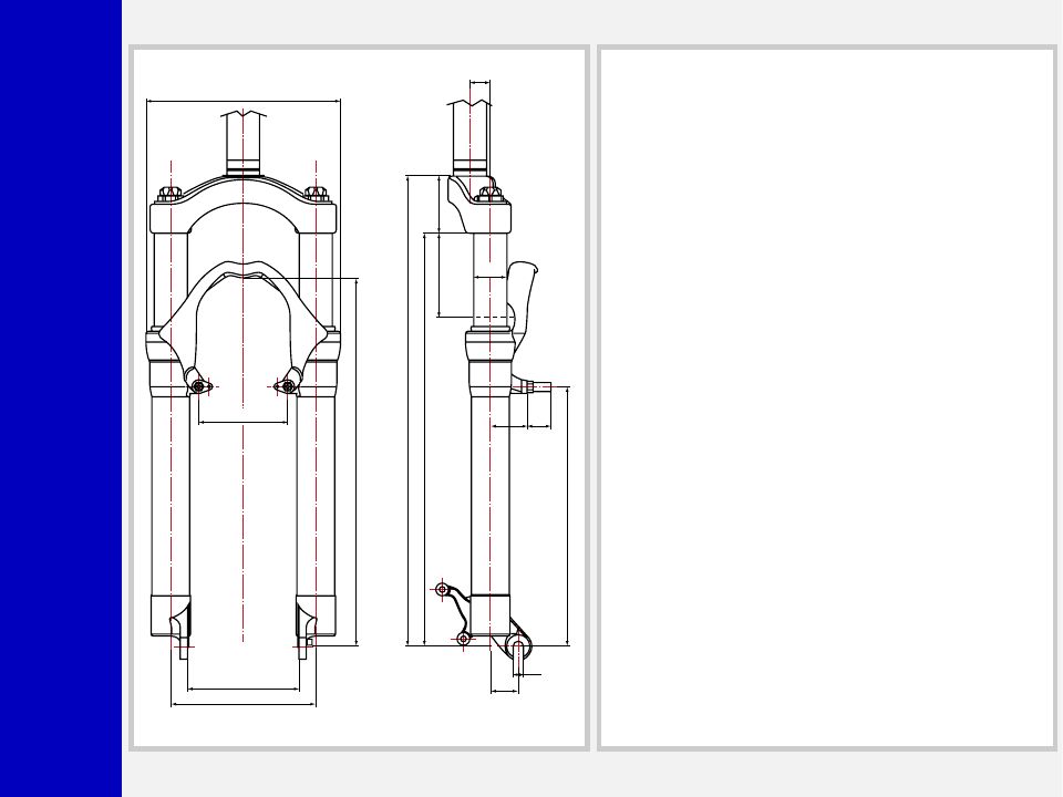
100
80
130
175
352.5
TRA
VEL 80
L.MAX=460.5
L.L.=450.5 L.MIN=370.5
395.5
33 22
Ø30
18
25
9.2
55
248.5
±
2
±
2
GENERAL
• The Z3 fork is sprung by a mechanical coil system and uses
hydraulic rebound damping.
• Spring pre-load adjustment controlled via external top mount
adjuster, rebound damping adjustment controlled by adjuster
inside each fork leg.
• Stanchions fitted into steering crown by cryofit technique. Full
length bushings guarantee superior rigidity.
• Sliders and arch are an integral assembly for reduced weight
and improved rigidity.
• Parts subjected to friction are cooled and lubricated by a
specially formulated oil.
Steer tube: EASTON aluminum steer tube available for 1 1/8”
diameter, threadless.
Crown: Forged and CNC-machined BAM
❊
aluminum alloy.
Arch: Cast magnesium alloy.
Stanchions: anodized EASTON aluminum with variable butting.
Springs: Constant pitch springs.
Sliders: Forged and CNC-machined BAM
❊
aluminum alloy. Left
slider comes with supports for disc brake caliper.
Slider bushing: Full length guide bushings composed of a
copper base and impregnated with an anti-friction coating.
Seals: Computer designed oil seals guarantee the highest quality
seals available.
Oil: Specially formulated oil which eliminates foaming and viscos-
ity breakdown while providing complete stiction-free performance.
Fork leg oil: 85 cc type EBH 16 - SAE 7.5.
❊
BAM: Bomber Aerospace Material.
Special alloy developed from aerospace material.

Z3
B
A
M
8
0
GENERAL RULES FOR
CORRECT OVERHAULING
AND MAINTENANCE
1. Where specified, assemble and disas-
semble the shock absorption system
using the MARZOCCHI special tools
only.
2. On reassembling the suspension sys-
tem, always use new seals.
3. Clean all metal parts with a special,
preferably biodegradable solvent, such
as trichloroethane or trichloroethylene.
4. Before reassembling, lubricate all parts
in contact with each other using sili-
cone fat spray or a specific oil for seals.
5. Always grease the lip seal rings before
reassembling.
6. Use wrenches with metric size only.
Wrenches with inch size might dam-
age the fastening devices even when
their size is similar to that of the wrenches
in metric size.
INSTRUCTIONS

Z3
B
A
M
8
0
FAILURES, CAUSES AND REMEDIES
This paragraph reports some failures that may occur when using the fork. It also indicates possible causes and suggests a remedy. Always
refer to this table before doing any repair work.
Oil leaking through the bottom of slider
O-ring on the pumping rod nut is damaged
Replace the O-ring
Oil leaking though the top of slider
1. Oil seal is worn out
2. Stanchion tube is scored
3. Excessive dirt on oil seal
1. Replace oil seal
2. Replace oil seal and crown and stan-
chions assembly
3. Clean the oil seal seat and replace oil
seal
Fork has not been used for some time and
is locked out
Oil seals and dust seals tend to stick to
stanchion tubes
Raise dust seal and lubricate stanchion
tube, dust seal and oil seal
Excessive play of stanchions in the sliders
Pilot bushings are worn
Replace pilot bushings
FAILURES
CAUSES
REMEDIES

Z3
B
A
M
8
0
RECOMMENDATIONS FOR
MAINTENANCE
MARZOCCHI forks are based on ad-
vanced technology, supported by year-
long experience in the field of profes-
sional mountain biking. In order to achieve
best results, we recommend to check and
clean the area below the dust seal and the
stanchion tube after each use and lubri-
cate with silicone oil.
INSTALLATION
Installing the Z3 fork on a bicycle is a very
delicate operation that should be carried
out with extreme care. The installation
should always be checked by one of our
Technical Service Centers.
WARNING: Steer tube/headset
mounting and adjustment must be
carried out in compliance with the head-
set manufacturer’s instructions. Improper
installation may jeopardize the safety of
the rider.
To replace it, contact one of our Technical
Service Centers with the required tools.
WARNING: In case of improper
installation of the steer tube into the
crown, the rider might lose control of his/
her bicycle, thus jeopardizing his/her
safety.
WARNING: Brake supports fea-
ture fixing pins or - as an option -
bolts. Never remove these pins (or bolts),
as they help keep brake arch-and-sliders-
assembly locked securely together.
DISC BRAKE SYSTEM ASSEMBLY
Assembling the brake caliper onto the
slider is a very delicate operation that
should be carried out with extreme care.
Improper assembly might overstress the
caliper supports which might break.
When installing the disc brake system, be
sure to properly follow the instructions
given by the manufacturer.
Z3
B
A
M
8
0
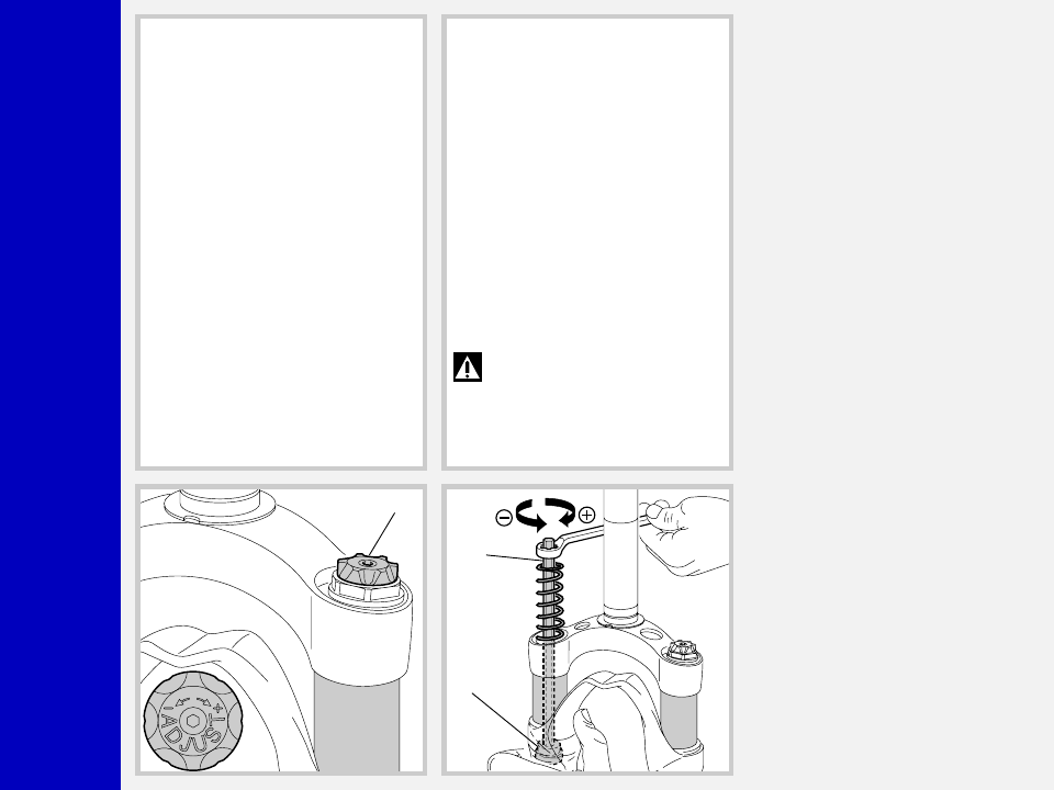
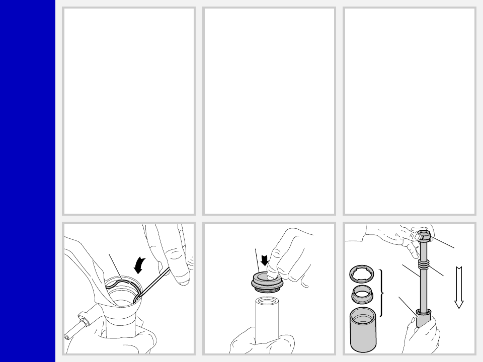
REBOUND ADJUSTMENT VIA IN-
NER PUMPING ROD (Fig. B)
The adjuster controlling REBOUND damp-
ing adjustment is accommodated inside
pumping rod (14) inside each fork leg.
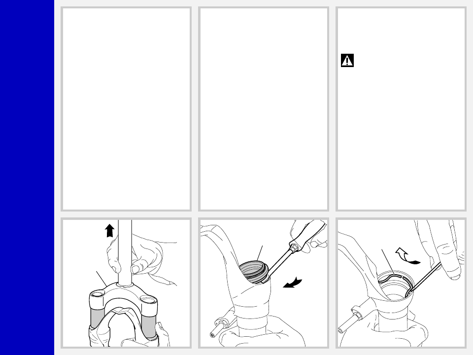
To access the adjuster, unscrew the top
cap (4) and push the stanchion tubes fully
down (see Fig. 1).
Fit the supplied hexagon rod (C) into the
stanchion tube and into the adjuster inner
hole. Rotate the adjuster clockwise for
harder damping, counterclockwise to sof-
ten it.
Refit the cap (4) and tighten it to the
specified torque (see fig. 24).
WARNING: Do not remove the
springs or this will alter the amount
of oil inside the fork legs.
ADJUSTMENT
SPRING PRELOAD (Fig. A)
Spring preload determines COMPRES-
SION damping and is adjusted by turning
the adjustment knob (3) on the top of the
fork legs. From the factory the Z3 is set at
minimum preload, i.e. the adjustment knob
completely unscrewed counterclockwise.
However, springs are slightly preloaded
to counteract static loads. By turning the
adjustment knob clockwise, the preload is
increased up to the maximum value equal
to 15 mm spring preload. This adjustment
is essential in order to have the right Z3
response for the rider’s weight and riding
style.
3
C
14

Z3
B
A
M
8
0
▲
▲
▲
▲
▲
▲
▲
▲
▲
▲
▲
▲
▲
▲
▲
▲
▲
▲
DISASSEMBLY
GENERAL
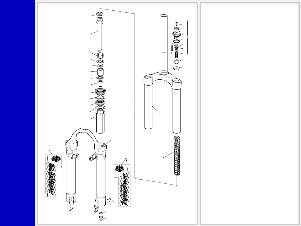
– The reference numbers given in this section relate to the components shown in the fork exploded view.
– Before starting any operation. please read the diagram below. It shows the quickest procedure and the exact disassembling
sequence. Locate the part you need to remove in the diagram, then look at the arrows to determine which other parts you need to
remove first.
DISASSEMBLY DIAGRAM
FORK LEG OIL CHANGE
PUMPING ROD CHANGE
FOOT NUT FIG. 3
SPRING FIG. 2
DUST SEAL FIG. 5
STOP RING. 6
OIL SEAL FIG. 7
PUMPING ROD FIG. 10
REBOUND SPRING FIG. 10
VALVE ASSEMBLY CHANGE
PILOT BUSHING AND SEAL
ASSEMBLY CHANGE
STANCHION TUBE CAP FIG. 1
FOOT BUFFER FIG. 10
CROWN AND STANCHIONS
ASSEMBLY FIG. 4
SPRING CHANGE
UPPER WASHER FIG. 8
STOP RING FIG. 11
PILOT BUSHING FIG. 9
VALVE ASSEMBLY FIG. 11
Z3
B
A
M
8
0
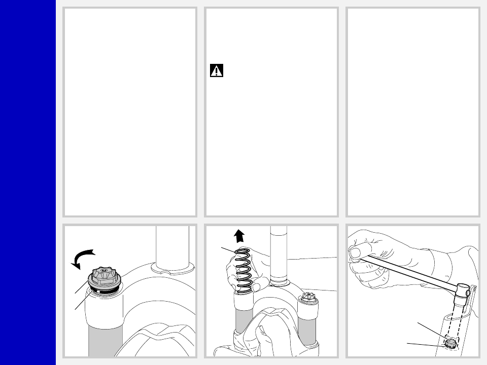
SPRING CHANGE
FIG. 1
Unscrew the caps (4) with a 21 mm socket
wrench.
Remove the caps complete with O-ring (5)
from the stanchion tubes.
FIG. 2
Push the stanchion tubes into the sliders
and remove the lower washer (11) and
the spring (12) from each fork leg.
Drain all oil from the fork legs.
WARNING: Remember to always
recycle any used oil.
To change the fork leg oil follow the
procedure as described in section
“REASSEMBLY” from Fig. 22 to Fig. 24.
PILOT BUSHING AND SEAL
ASSEMBLY CHANGE
FIG. 3
Turn the fork leg upside-down and un-
screw the foot nuts (26) complete with O-
ring (25) by the use of a 15 mm socket
wrench.
4
5
12
25
26
Z3
B
A
M
8
0
FIG. 4
Withdraw the crown and stanchion tubes
assembly (1) from the sliders.
1
19
20
FIG. 5
Remove the dust seal (19) from the top of
the sliders using a small screwdriver.
FIG. 6
Remove the stop ring (20) from the sliders
by placing the screwdriver bit in one of the
three openings on the stop ring.
IMPORTANT: when removing the
stop ring, make sure not to damage
its seat.
Z3
B
A
M
8
0
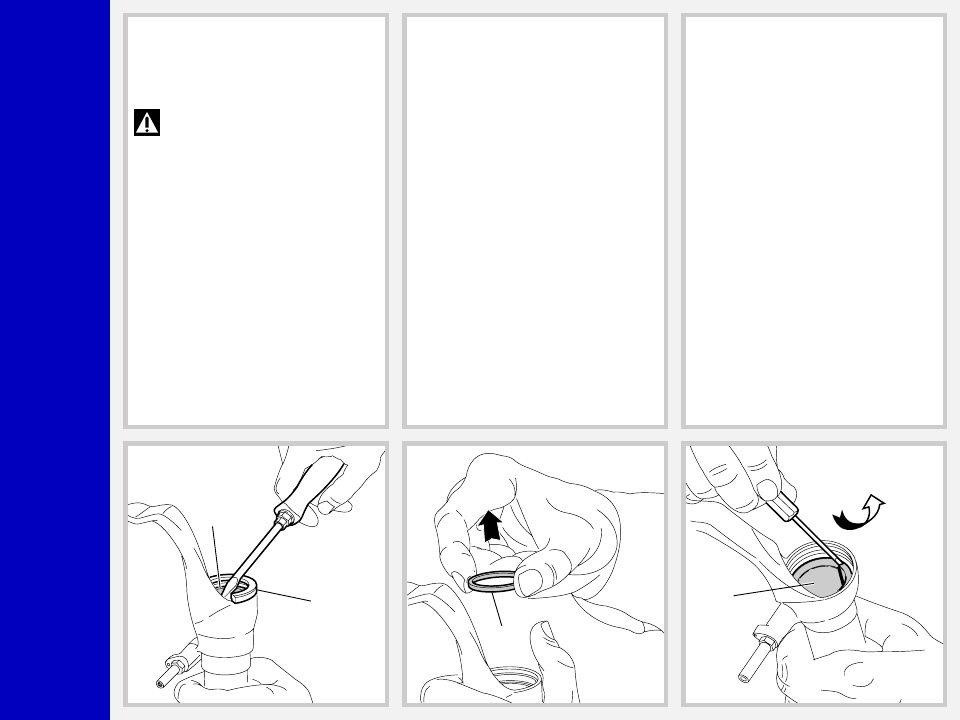
FIG. 7
Fit the slider protector (A) onto the slider
and remove the oil seal (21) with the help
of a large screwdriver.
IMPORTANT: when removing the
oil seal, make sure not to damage
its seat. Once removed the oil seals should
not be used again.
21
A
22
23
FIG. 8
Remove the upper washer (22) from the
slider.
FIG. 9
Fit the bit of a small screwdriver into upper
edge slot of the pilot bushing (23) and lift
gently. Pull the bushing out of the slider
and make all necessary changes.
Z3
B
A
M
8
0
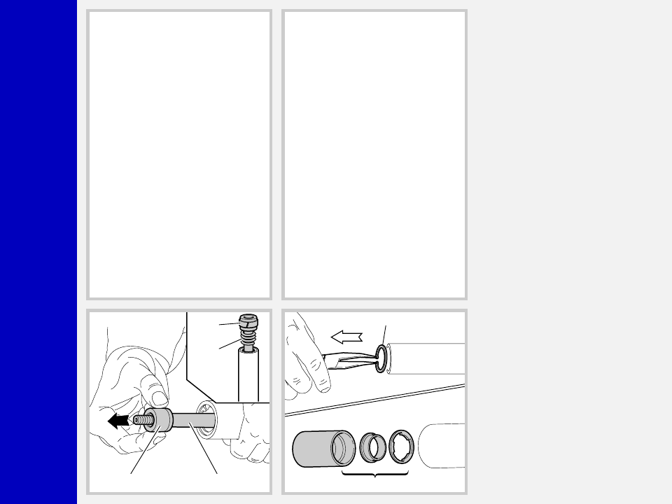
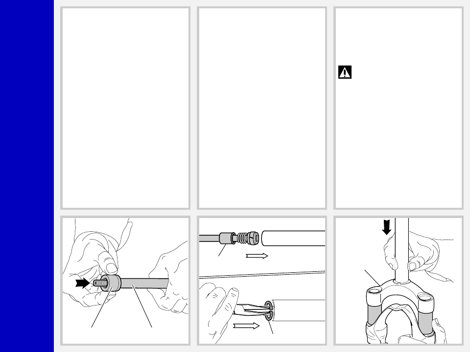
PUMPING ROD CHANGE
FIG. 10
Remove the foot buffer (18) from the
pumping rod (14) end.
Withdraw the pumping rod (14) and the
rebound spring (15) from the stanchion
tube opposite side. Replace the seal ring
(13) if damaged or worn out.
13
15
18
14
17
16
VALVE ASSEMBLY CHANGE
FIG. 11
To check that the valve assembly is oper-
ating correctly, it is necessary to work on
the inside of the stanchion tube.
Slip off the stop ring (17) using pointed
pliers.
Pull the valve assembly (16) out of the tube
with one finger in the same sequence as in
the figure.
Z3
B
A
M
8
0
REASSEMBLY
CAUTION: before reassembling,
all metal components should be
washed carefully with inflammable, pref-
erably biodegradable, solvent and dried
with compressed air.
PILOT BUSHING AND SEAL
ASSEMBLY
FIG. 12
Check that no dirt or debris is between
slider and bushing. Insert the pilot bushing
(23) into place so that it adheres to the
slider.
23
22
21
B
FIG. 13
Fit the upper washer (22) into the slider so
that it touches the pilot bushing.
FIG. 14
Lubricate the oil seal (21) and place it onto
the seal press (B) with the hollow side
toward the slider.
Press the oil seal until it touches the lower
washer by using the above seal press.
Z3
B
A
M
8
0
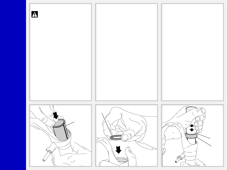
FIG. 15
Insert the stop ring (20) into the slider
making sure it is properly seated into
place.
20
FIG. 16
Lubricate the dust seals (19) and fit them
into the stanchions from the spring end.
19
VALVE AND PUMPING ROD
ASSEMBLY
FIG. 17
After having overhauled or replaced the
valve unit and after having cleaned the
inside of the tube, reassemble. Assemble
valve components (16), in correct se-
quence.
Then fit pumping rod (14) with seal ring
(13) and rebound spring (15) into the
valve assembly (16).
14
15
13
16
Z3
B
A
M
8
0
18
14
17
16
FIG. 18
Reassemble the foot buffer (18) onto the
end part of pumping rod (14).
FIG. 19
Fit this assembly into the stanchion tube
and properly seat the valve assembly
(16).
Insert the stop ring (17).
CROWN AND STANCHIONS
ASSEMBLY
FIG. 20
Fit the crown and stanchions assembly -
with the dust seals in place - gently into the
sliders seals.
WARNING: Be sure to fit the stan-
chions squarely into the sliders or
the sealing surfaces will damage.
Press the crown and stanchions assembly
fully down and check that pumping rod
ends (14) are coming out through the
bottom of the sliders.
Check to see that the stanchion tubes slide
unrestricted by cycling the fork up and
down several times.
The tube should slide freely inside the seal
assembly without any side play. In the event
it is too hard or too soft, repeat the previous
steps described above and check compo-
nents to ensure they are not damaged.
Place the dust seals (19) on top of the sliders.
1
Z3
B
A
M
8
0
26
25
Nm
12
40
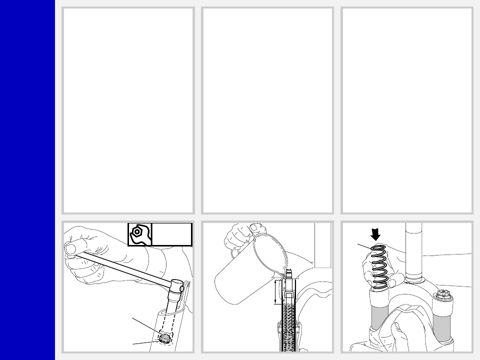
FIG. 21
Grease the O-ring (25) on the foot nut (26)
and screw the nut on the pumping rod
thread (14).
Tighten to 12 Nm.
Check to verify that the stanchion tubes
slide properly through the stroke by pump-
ing them up and down several times.
HOW TO FILL WITH OIL
FIG. 22
Pour oil little by little when the stanchion
tubes are fully down and then pump with
the crown so as to have a better filling.
Check that the oil level is 40 mm/1.57 in.
from the top of the stanchion tube, in both
legs.
SPRING AND CAP
FIG. 23
Fit the springs (12) into each stanchion
tube.
12
Z3
B
A
M
8
0
4
5
Nm
12
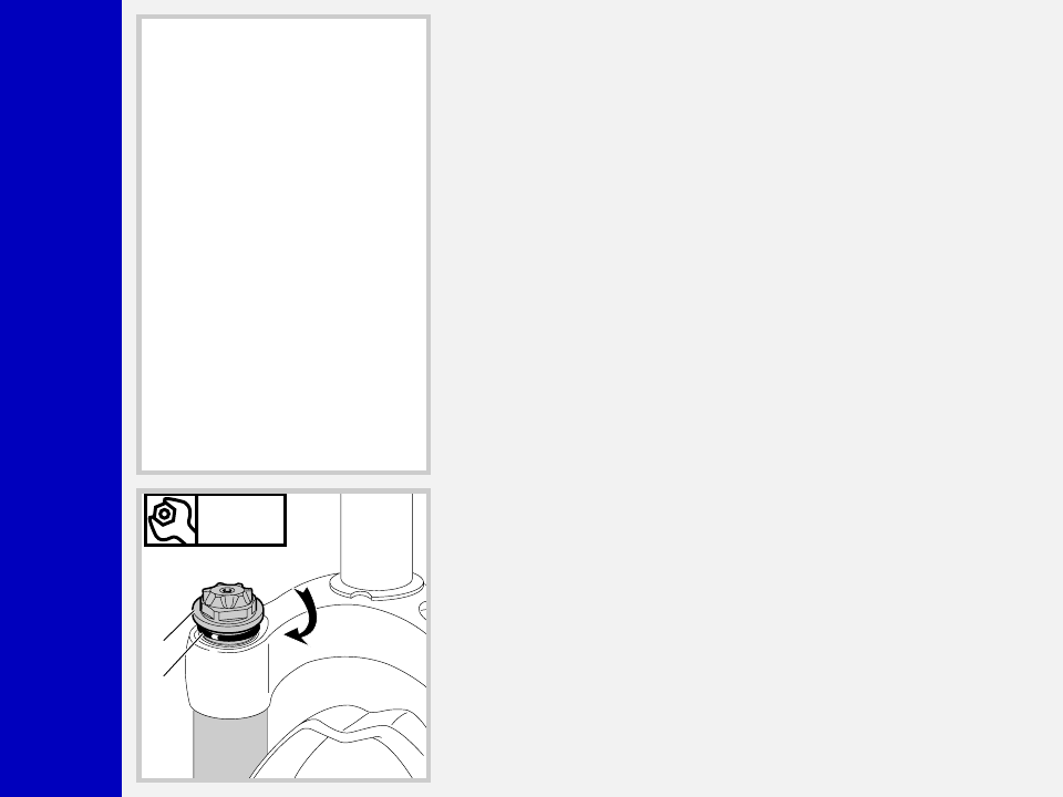
FIG. 24
Lubricate the O-ring (5) on the cap (4).
Turn the preload adjuster (9)
counterclockwise until it is at its minimum
setting and install the lower washer (11).
Start the caps with the O-ring (5) in place
into the stanchion tube threads by hand.
Tighten caps (4) to 12 Nm.
Z3
B
A
M
8
0
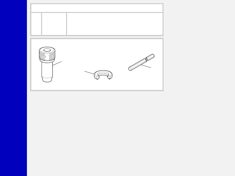
SPECIFIC TOOLS
Ref.
Item.
Description and use
A
536003 AB
Slider protector: to remove the oil seal from the slider
B
R 5068
Oil seal press: to press oil seal into the slider
C
R 5085
Hexagon wrench: to set rebound adjuster
B
A
C
Wyszukiwarka
Podobne podstrony:
2000 z3 flylight 100
2000 z3 m80
2000 z3 5
2000 z3 qr20
Młody Technik 2000 Volwo S 80
Ustawa o własności lokali, Dz.U. 2000 nr 80 poz. 903 [Tekst aktu]
2000 z2 atom bomb 80
cosmopolitan bmw z3 2000 113
plik (80) ppt
03 2000 Revisions Overview Rev 3 1 03
Natura 2000
PiU P Z3
brzuch 1999 2000
opiekunka dziecieca 513[01] z3 02 u
MAZDA B3000 2000
więcej podobnych podstron