1 - 3
CCNP: Building Scalable Internetworks v5.0 – Case Study 3 – OSPF Five Routers Copyright
© 2006, Cisco Systems, Inc
Case Study 3 OSPF Five Routers (Optional)
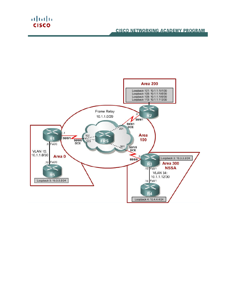
Topology Diagram
Using a Cisco router as the Frame Relay switch:
2 - 3
CCNP: Building Scalable Internetworks v5.0 – Case Study 3 - OSPF Five Routers Copyright
© 2006, Cisco Systems, Inc
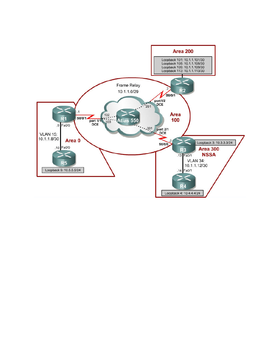
Using an Adtran Atlas 550 as the Frame Relay switch:
Instructions
Plan, design, and implement the International Travel Agency (ITA) network
shown in the diagram and described below. Verify that all configurations are
operational and functioning according to the guidelines.
Scenario
The ITA needs its core network set up for OSPF with the following
specifications. Use the addressing scheme shown in the diagram.
• Configure the OSPF backbone area on the Ethernet connection between R1
and R5.
• Configure the Frame Relay subnet as a point-to-multipoint network in area
100.
• Configure R2’s loopback interfaces to be in area 200. Summarize this area
with the most efficient summary.
• Configure the Ethernet connection between R3 and R4 to be in area 300.
• Add the loopback on R3 to area 300.
• Make area 300 a totally NSSA area.

3 - 3
CCNP: Building Scalable Internetworks v5.0 – Case Study 3 - OSPF Five Routers Copyright
© 2006, Cisco Systems, Inc
• Redistribute the loopback networks on R4 that do not belong in any OSPF
area.
• Create virtual links as necessary for full connectivity.
• Make sure that all loopback interfaces get advertised with the correct subnet
mask.
Wyszukiwarka
Podobne podstrony:
CCNP1 lab 3 2 en
CCNP1 lab 7 4 en
CCNP1 lab 8 1 en
CCNP1 lab 5 1 en
CCNP1 lab 2 2 en
CCNP1 lab 2 4 b en
CCNP1 lab 2 1 en
CCNP1 lab 6 2 en
CCNP1 lab 2 3 en
CCNP1 lab 5 2 en
CCNP1 lab 3 3 en
CCNP1 lab 2 5 en
CCNP1 lab 2 4 a en
CCNP1 lab 4 1 en
CCNP1 lab 4 3 b en
CCNP1 lab 1 0 en
CCNP1 lab 5 5 en
CCNP1 lab 7 2 en
CCNP1 lab 6 1 en
więcej podobnych podstron