C 22
SERVICE INFORMATION
S T A R T I N G WITH S E R I A L NO. 10A01
M c l N T O S H L A B O R A T O R Y INC. 2 C H A M B E R S S T R E E T BINGHAMTON, NEW Y O R K
C
2
2

E L E C T R I C A L S P E C I F I C A T I O N S
Frequency Response
+0.5 to -0.5 dB, 20Hz to 20,000Hz
Distortion
Less than 0.2% at 10 volts output
Less than 0.02% at 3 volts output
Input Sensitivity (phono 1, phono 2, tape head)
2 millivolts for 2.5 volts output at 1kHz
Input Sensitivity (Microphone)
2.5 millivolts for 2.5 volts output
Input Sensitivity (aux, tape, tuner)
0.25 volts for 2.5 volts output
Hum And Noise (phono 1, phono 2, tape head)
74 dB below 10 millivolts input
Hum And Noise (aux, tape, tuner)
85 dB below rated output
Output (main)
2.5 volts with rated input. Up to 10 volts
can be developed without distortion.
Output (tape)
0.25 volts with rated input. Phono input
signal of 10 millivolts produces 1.25 volts
output.
Output (L & R)
1.0 volts with rated input on both channels.
A level control adjusts output.
Bass Control
+20 dB at 20Hz
Treble Control
+20 dB at 20,000Hz
LP Filter
Flat or sharp cutoff below 50Hz (down 30 dB @ 20Hz).
HF Filter
Flat or sharp cutoff above 5000Hz (down 30 dB @ 20,000Hz).
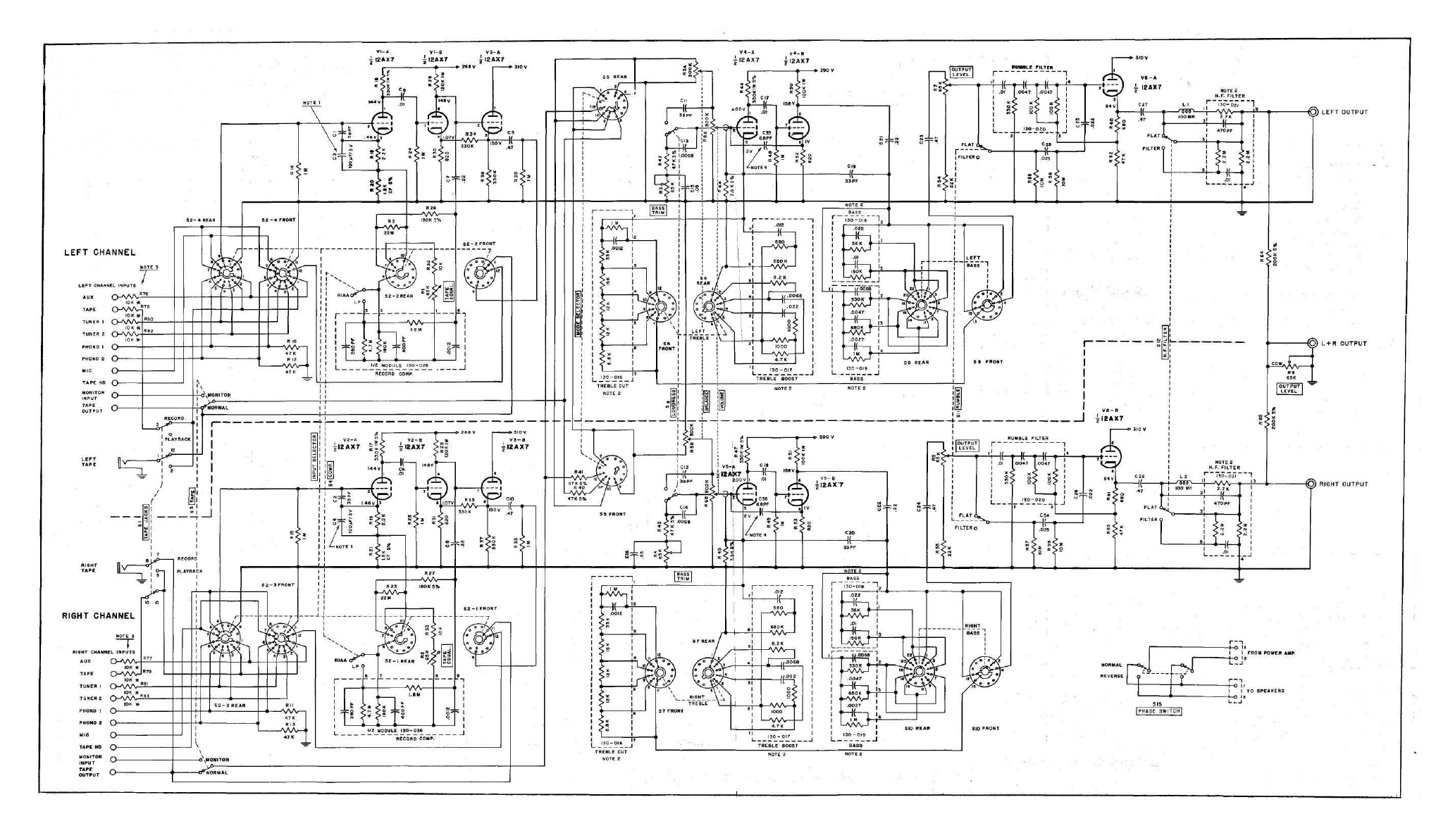
PREAMP. SECTION
154
- 318
Unless otherwise specified, resistance values are
in ohms, 1/2 watt, and 10% tolerance. Capacitance
values smaller than 1 are in microfarads (µF);
values greater than 1 are in picofarads (pF).
Resistors marked with * are 1/4W.
The terminal numbering of rotary switches and printed
circuit board wires is for reference only.
All voltages are measured under the following condi-
tions:
1. Use of an 11 megohm input impedance VTVM
2. All voltages ±10% with respect to ground
3. AC input at 117 volts, 50/60 cycles
4. No signal at input terminals
5. Front panel controls at normal positions
S C H E M A T I C N O T E S
1. In early units C3 & 4 were 50µF.
2. C22's built before 1965 used circuit modules
made by Erie Electronics. In 1965, we changed
to Sprague Electric Co. The Sprague modules
are electrically equivalent to the Erie modules
but differ mechanically. The newer Sprague
modules are used for replacement when servicing
early C22 units. For data on replacing the
old Erie modules with the Sprague modules, refer
to Mclntosh Service Bulletin #108.
3. In early units R76 thru R83 do not appear.
4. In early units C35 & 36 do not appear.
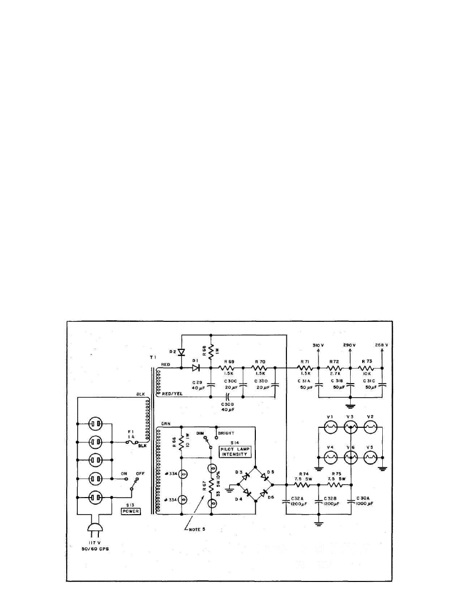
5. In early units R67 was 50 ohms.
POWER SUPPLY
154-317

R E P L A C E M E N T P A R T S
All parts not listed are common items obtain-
able from radio parts jobbers.
Replacement parts may be obtained when ordered
by PART NUMBER from:
Mclntosh Laboratory Inc.
Customer Service Department
2 Chambers Street
Binghamton, New York 13903
(telephone 607-723-3512)
CAPACITORS
Symbol Part
Number Description Number
C3,4 Elect. 100 µF 3V 066-047
C29 Elect. 40µF 200V 066-049
C30 Elect. 1000/40/20 /20µF 066-037
25/200/35o/35ov
C31 Elect. 50/50/50 µF 066-033
350/350/300V
C32 Elect. 1200/1200µF 066-029
30/30V
DIODES
D1,2 Se. rectifier 070-005
D3,4 Si. rectifier 070-014
D5,6 Si. rectifier 070-014
PUSES
F1 Fuse 1 amp 089-002
CHOKES
L1 ,2 Choke 100 mH . 122-004
POTENTIOMETERS
R1, 2 Tape equal. (1/2 Dia. ) 134-059
R1, 2 Tape equal. (5/8 Dia. ) 134-186
R3,4 Bass trim (1/2 Dia. ) 134-059
R3,4 Bass trim (5/8 Dia.) 134-186
R5 Balance control 134--061
R6 Volume control 134-060
R7,8,9 Output level (5/8 Dia.) 134-186
R7,8,9 Output level (1/2 Dia. ) 134--059
RESISTORS
R16,17 Low noise 330K 5% 1W 144-005
R20,21 Low noise 1.8K 5% 1/2W 144-002
R46,147 Low noise 330K 5% 1W 144-005
R67 Wirewound 33 ohm 10% 5W 139-007
R74,75 Wirewound 7.5 ohm 10% 5W 139-010

S1
S2
S3
S4
S5
S6,7
S8
S9,10
S11
S12
S13
S14
S15
T1
- - -
SWITCHES
Tape jacks switch
Input selector switch
Tape switch
Comp. switch
Mode selector switch
Treble control switch
Loudness switch
Bass control switch
Rumble switch
H.F. filter switch
Power switch
Pilot lamp switch
Phase switch
TRANSFORMERS .
Power transformer
MODULES
Treble cut
Treble boost
Bass, upper
Bass, lower
Rumble filter
H.P. filter
Phono equalization
LAMPS
#334 (indicator)
Festoon (indicator glass)
FRONT PANEL & TRIM
Front panel
Front panel glass
End cap, right
End cap, left
Volume control knob
Mode selector knob
Input selector knob
Balance knob
Bass control knob
Tape jacks knob
Treble control knob
Rocker switch knob
Level set knob
•
146-053
146-049
148-006
148-006
149-108
146-052
148-006
146-051
148-006
148-006
148-005
148-003
148-007
159-019
130-016
130-017
130-018
130-019
130-020
130-021
130-026
058-003
058-033
043-359
016-034
018-043
018-044
043-253
043-253
043-253
043-253
O43-428
043-428
043-428
090-007
090-010
MOUNTING SYSTEM
Shelf bracket (right) 043-592
Shelf bracket (left) 043-593
Mounting template #100 038-179
Hardware package 043-448
MISCELLANEOUS ITEMS
Line cord 170-021
Fuse holder 178-001
Shipping carton 033-027
Owners manual 038-027
Plastic feet 017-041
Shorting plug 127-001
Indicator glass 016-036
Audio cable (6') 170-015
Audio cable (1 phone, 170-016
1 phono)
20C0425S6-8M270
S C H E M A T I C P A R T N O . 0 3 8 - 2 7 0
Be122002
Wyszukiwarka
Podobne podstrony:
McIntosh MC 250 Service Manual
hplj 5p 6p service manual vhnlwmi5rxab6ao6bivsrdhllvztpnnomgxi2ma vhnlwmi5rxab6ao6bivsrdhllvztpnnomg
Oberheim Prommer Service Manual
Korg SQ 10 Service Manual
MAC1500 service manual
Kyocera Universal Feeder UF 1 Service Manual
Proview RA783 LCD Service Manual
indesit witp82euy Service Manual
Glow Worm installation and service manual Hideaway 70CF UIS
Proview PZ456 LCD Service Manual
Glow Worm installation and service manual Ultimate 50CF UIS
ewm2000 service manual
Glow Worm installation and service manual Ultimate 60CF UIS
Proview SH770I LCD Service Manual
M23 Service Manual
Glow Worm installation and service manual Glow micron 60
Konica Minolta QMS 7115, 7118 Service Manual
Honda NSR125 '87 Service Manual
więcej podobnych podstron