
TIRES AND WHEELS
CONTENTS
page
page
TIRES . . . . . . . . . . . . . . . . . . . . . . . . . . . . . . . . . . 1
WHEELS . . . . . . . . . . . . . . . . . . . . . . . . . . . . . . . . 8
TIRES
INDEX
page
page
DESCRIPTION AND OPERATION
RADIAL-PLY TIRES . . . . . . . . . . . . . . . . . . . . . . . 2
REPLACEMENT TIRES . . . . . . . . . . . . . . . . . . . . 3
SPARE TIRE (TEMPORARY) . . . . . . . . . . . . . . . . 2
TIRE INFLATION PRESSURES . . . . . . . . . . . . . . 2
TIRE INFORMATION . . . . . . . . . . . . . . . . . . . . . . 1
TIRE PRESSURE FOR HIGH—SPEED
OPERATION . . . . . . . . . . . . . . . . . . . . . . . . . . . 3
DIAGNOSIS AND TESTING
LEAD CORRECTION CHART . . . . . . . . . . . . . . . . 4
PRESSURE GAUGES . . . . . . . . . . . . . . . . . . . . . 3
TIRE NOISE OR VIBRATION . . . . . . . . . . . . . . . . 4
TIRE WEAR PATTERNS . . . . . . . . . . . . . . . . . . . . 3
TREAD WEAR INDICATORS . . . . . . . . . . . . . . . . 3
SERVICE PROCEDURES
MATCH MOUNTING . . . . . . . . . . . . . . . . . . . . . . . 6
REPAIRING LEAKS . . . . . . . . . . . . . . . . . . . . . . . 7
ROTATION . . . . . . . . . . . . . . . . . . . . . . . . . . . . . . 6
CLEANING AND INSPECTION
CLEANING OF TIRES . . . . . . . . . . . . . . . . . . . . . 7
DESCRIPTION AND OPERATION
TIRE INFORMATION
Tires are designed and engineered for each specific
vehicle. They provide the best overall performance
for normal operation. The ride and handling charac-
teristics match the vehicle’s requirements. With
proper care they will give excellent reliability, trac-
tion, skid resistance, and tread life.
Driving habits have more effect on tire life than
any other factor. Careful drivers will obtain, in most
cases, much greater mileage than severe use or care-
less drivers. A few of the driving habits which will
shorten the life of any tire are:
• Rapid acceleration
• Severe application of brakes
• High-speed driving
• Taking turns at excessive speeds
• Striking curbs and other obstacles
Radial ply tires are more prone to irregular tread
wear. It is important to follow the tire rotation inter-
val shown in the section on Tire Rotation. This will
help to achieve a greater tread-life potential.
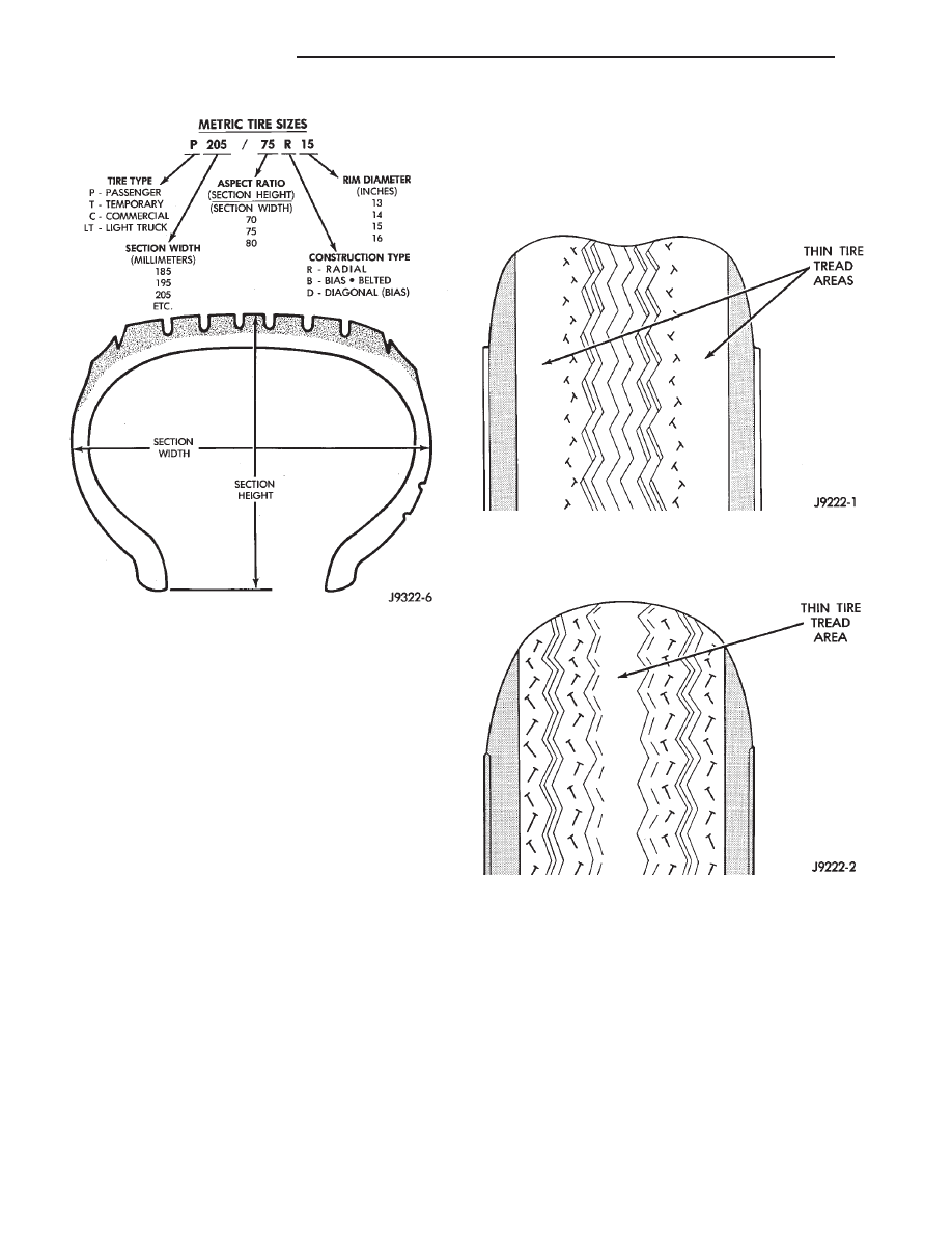
TIRE IDENTIFICATION
Tire type, size, aspect ratio and speed rating are
encoded in the letters and numbers imprinted on the
side wall of the tire. Refer to the chart to decipher
the tire identification code (Fig. 1).
Performance tires will have a speed rating letter
after the aspect ratio number. The speed rating is not
always printed on the tire sidewall. The letter S indi-
cates that the tire is speed rated up to 112 mph.
• Q up to 100 mph
• T up to 118 mph
• U up to 124 mph
• H up to 130 mph
• V up to 149 mph
• Z more than 149 mph (consult the tire manu-
facturer for the specific speed rating)
An All Season type tire will have either M + S, M
& S or M—S (indicating mud and snow traction)
imprinted on the side wall.
TIRE CHAINS
Tire snow chains may be used on certain models.
Refer to Owner’s Manual for more information.
ZJ
TIRES AND WHEELS
22 - 1
RADIAL-PLY TIRES
Radial-ply tires improve handling, tread life, ride
quality and decrease rolling resistance.
Radial-ply tires must always be used in sets of four
and under no circumstances should they be used on
the front only. They may be mixed with temporary
spare tires when necessary. A maximum speed of 50
MPH is recommended while a temporary spare is in
use.
Radial-ply tires have the same load-carrying capac-
ity as other types of tires of the same size. They also
use the same recommended inflation pressures.
The use of oversized tires, either in the front or
rear of the vehicle, can cause vehicle drive train fail-
ure. This could also cause inaccurate wheel speed
signals when the vehicle is equipped with Anti-Lock
Brakes.
It is recommended that tires from different manu-
factures NOT be mixed. The proper tire pressure
should be maintained on all four tires. For proper
tire pressure refer to the Tire Inflation Pressure
Chart provided with the vehicle.
SPARE TIRE (TEMPORARY)
The temporary spare tire is designed for emer-
gency use only. The original tire should be repaired
and reinstalled at the first opportunity, or a new tire
purchased. Do not exceed speeds of 50 MPH. Refer to
Owner’s Manual for complete details.
TIRE INFLATION PRESSURES
Under inflation causes rapid shoulder wear, tire
flexing, and can result in tire failure (Fig. 2).
Over inflation causes rapid center wear and loss of
the tire’s ability to cushion shocks (Fig. 3).
Improper inflation can cause:
• Uneven wear patterns
• Reduced tread life
• Reduced fuel economy
• Unsatisfactory ride
• The vehicle to drift.
For proper tire pressure specification refer to the
Tire Inflation Pressure Chart provided with the vehi-
cle.
Tire pressures have been chosen to provide safe
operation, vehicle stability, and a smooth ride. Tire
pressure should be checked cold once per month.
Check tire pressure more frequently when the
Fig. 1 Tire Identification
Fig. 2 Under Inflation Wear
Fig. 3 Over Inflation Wear
22 - 2
TIRES AND WHEELS
ZJ
DESCRIPTION AND OPERATION (Continued)
weather temperature varies widely. Tire pressure will
decreases when the outdoor temperature drops.
Inflation pressures specified on the placards are
always cold inflation pressure. Cold inflation pres-
sure is obtained after the vehicle has not been oper-
ated for at least 3 hours. Or the vehicle is driven less
than one mile after being inoperative for 3 hours.
Tire inflation pressures may increase from 2 to 6
pounds per square inch (psi) during operation. Do not
reduce this normal pressure build-up.
WARNING: OVER
OR
UNDER
INFLATED
TIRES
CAN AFFECT VEHICLE HANDLING. THE TIRE CAN
FAIL SUDDENLY, RESULTING IN LOSS OF VEHICLE
CONTROL.
TIRE PRESSURE FOR HIGH—SPEED OPERATION
Chrysler Corporation advocates driving at safe
speeds within posted speed limits. Where speed lim-
its allow the vehicle to be driven at high speeds, cor-
rect tire inflation pressure is very important. For
speeds up to and including 75 mph (120 km/h), tires
must be inflated to the pressures shown on the tire
placard. For speeds in excess of 75 mph (120 km/h),
tires must be inflated to the maximum pressure spec-
ified on the tire sidewall.
Vehicles loaded to the maximum capacity should
not be driven at continuous speeds above 75 mph
(120 km/h).
WARNING: OVER
OR
UNDER
INFLATED
TIRES
CAN AFFECT VEHICLE HANDLING. THE TIRE CAN
FAIL SUDDENLY, RESULTING IN LOSS OF VEHICLE
CONTROL.
For emergency vehicles that are driven at speeds
over 90 mph (144 km/h), special high-speed tires
must be used. Consult tire manufacturer for correct
inflation pressure recommendations.
REPLACEMENT TIRES
The original equipment tires provide a proper bal-
ance of many characteristics such as:
• Ride
• Noise
• Handling
• Durability
• Tread life
• Traction
• Rolling resistance
• Speed capability
It is recommend that tires equivalent to the origi-
nal equipment tires be used when replacement is
needed.
Failure to use equivalent replacement tires may
adversely affect the safety and handling of the vehi-
cle.
The use of oversize tires not listed in the specifica-
tion charts may cause interference with vehicle com-
ponents. Under extremes of suspension and steering
travel, interference with vehicle components may
cause tire damage.
WARNING: FAILURE TO EQUIP THE VEHICLE WITH
TIRES HAVING ADEQUATE SPEED CAPABILITY
CAN RESULT IN SUDDEN TIRE FAILURE.
DIAGNOSIS AND TESTING
PRESSURE GAUGES
A high-quality air-pressure gauge is recommended
to check tire pressure. After checking with the gauge,
replace valve caps and finger tighten.
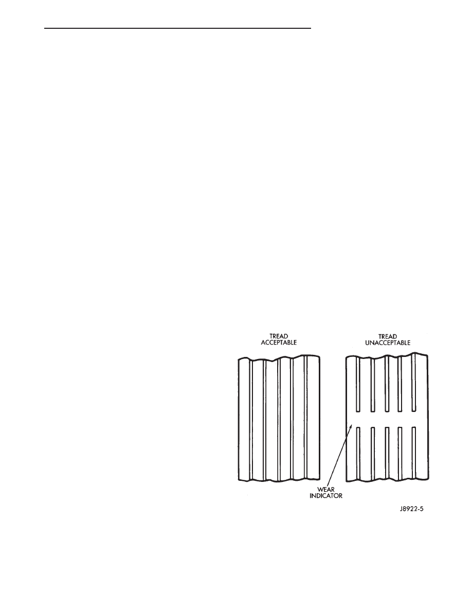
TREAD WEAR INDICATORS
Tread wear indicators are molded into the bottom
of the tread grooves. When tread depth is 1.6 mm
(1/16 in.), the tread wear indicators will appear as a
13 mm (1/2 in.) band.
Tire replacement is necessary when indicators
appear in two or more grooves or if localized balding
occurs (Fig. 4).
TIRE WEAR PATTERNS
Under inflation results in faster wear on shoulders
of tire. Over inflation causes faster wear at center of
tread.
Fig. 4 Tread Wear Indicators
ZJ
TIRES AND WHEELS
22 - 3
DESCRIPTION AND OPERATION (Continued)
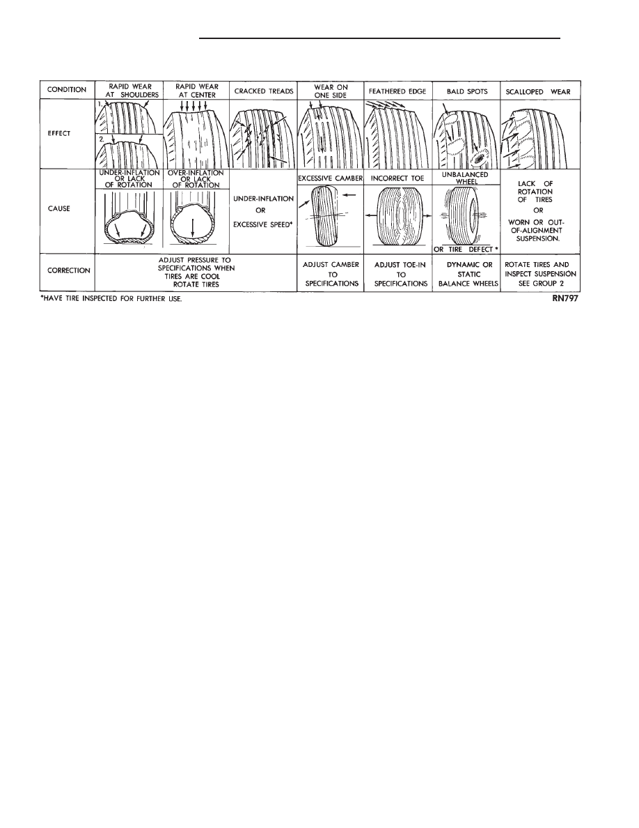
Excessive camber causes the tire to run at an
angle to the road. One side of tread is worn more
than the other.
Excessive toe-in or toe-out causes wear on the
tread edges of the tire, from dragging of tire. There is
a feathered effect across the tread (Fig. 5).
TIRE NOISE OR VIBRATION
Radial-ply tires are sensitive to force impulses
caused
by
improper
mounting,
vibration,
wheel
defects, or possibly tire imbalance.
To find out if tires are causing the noise or vibra-
tion, drive the vehicle over a smooth road at varying
speeds. Note the effect of acceleration and decelera-
tion on noise level. Differential and exhaust noises
will change in intensity as speed varies, while tire
noise will usually remain constant.
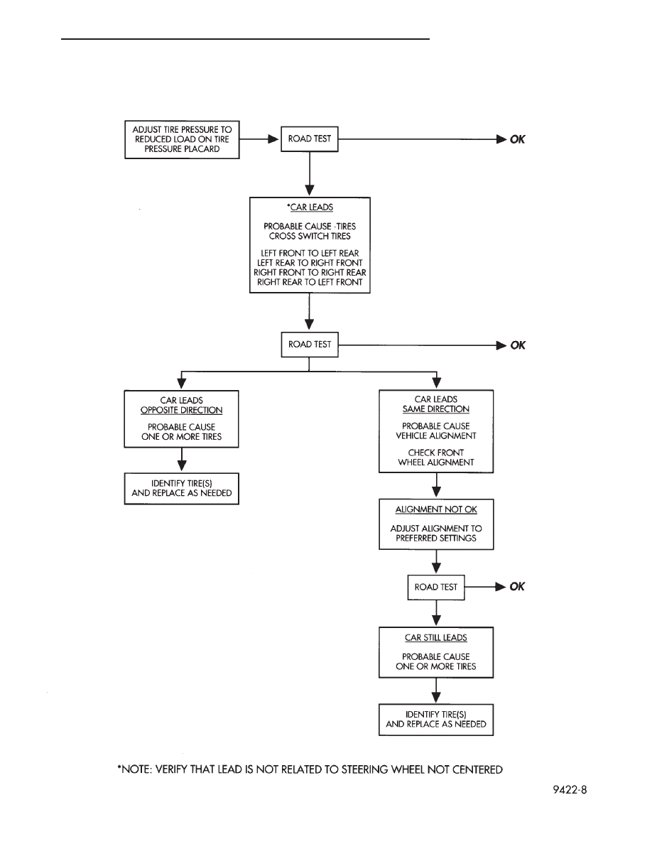
LEAD CORRECTION CHART
Use the following chart to correct vehicle leading
or drifting problems.
Fig. 5 Tire Wear Patterns
22 - 4
TIRES AND WHEELS
ZJ
DIAGNOSIS AND TESTING (Continued)
ZJ
TIRES AND WHEELS
22 - 5
DIAGNOSIS AND TESTING (Continued)
SERVICE PROCEDURES
ROTATION
Tires on the front and rear axles operate at differ-
ent loads and perform different steering, driving, and
braking functions. For these reasons;
• They wear at unequal rates
• Tend to develop irregular wear patterns
These effects can be reduced by timely rotation of
tires. The benefits of rotation are especially worth-
while. Rotation will:
• Increase tread life
• Help to maintain mud, snow, and wet traction
levels
• Contribute to a smooth, quiet ride
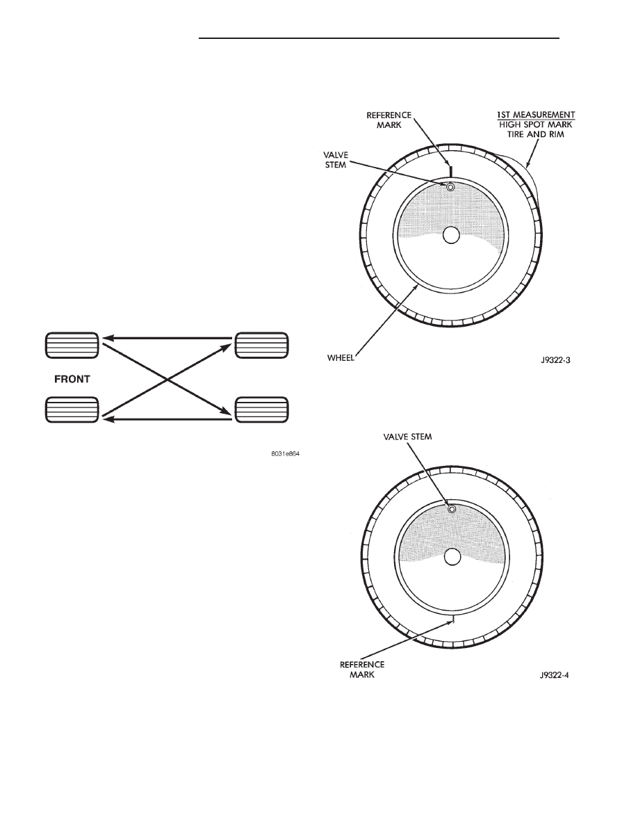
The suggested method of tire rotation is (Fig. 6).
Other rotation methods can be used, but they will
not provide all the tire longevity benefits.
MATCH MOUNTING
NOTE: Tires and wheels are not currently match
mounted at the factory.
Match mounting is a technique used to reduce
runout in the wheel/tire assembly. This means that
the high spot of the tire is aligned with the low spot
on the wheel rim. The high spot on the tire is
marked with a paint mark or a bright colored adhe-
sive label on the outboard sidewall. The low spot on
the rim is identified with a label on the outside of the
rim and a dot on the inside of the rim. If the outside
label has been removed the tire will have to be
removed to locate the dot on the inside of the rim.
Before dismounting a tire from its wheel, a refer-
ence mark should be placed on the tire at the valve
stem location. This reference will ensure that it is
remounted in the original position on the wheel.
(1) Measure the total indicator runout on the cen-
ter of the tire tread rib. Record the indicator reading.
Mark the tire to indicate the high spot. Place a mark
on the tire at the valve stem location (Fig. 7).
(2)
Break down the tire and remount it 180
degrees on the rim (Fig. 8).
(3) Measure the total indicator runout again. Mark
the tire to indicate the high spot.
(4) If runout is still excessive, the following proce-
dures must be done.
Fig. 6 Tire Rotation Pattern
Fig. 7 First Measurement On Tire
Fig. 8 Remount Tire 180 Degrees
22 - 6
TIRES AND WHEELS
ZJ
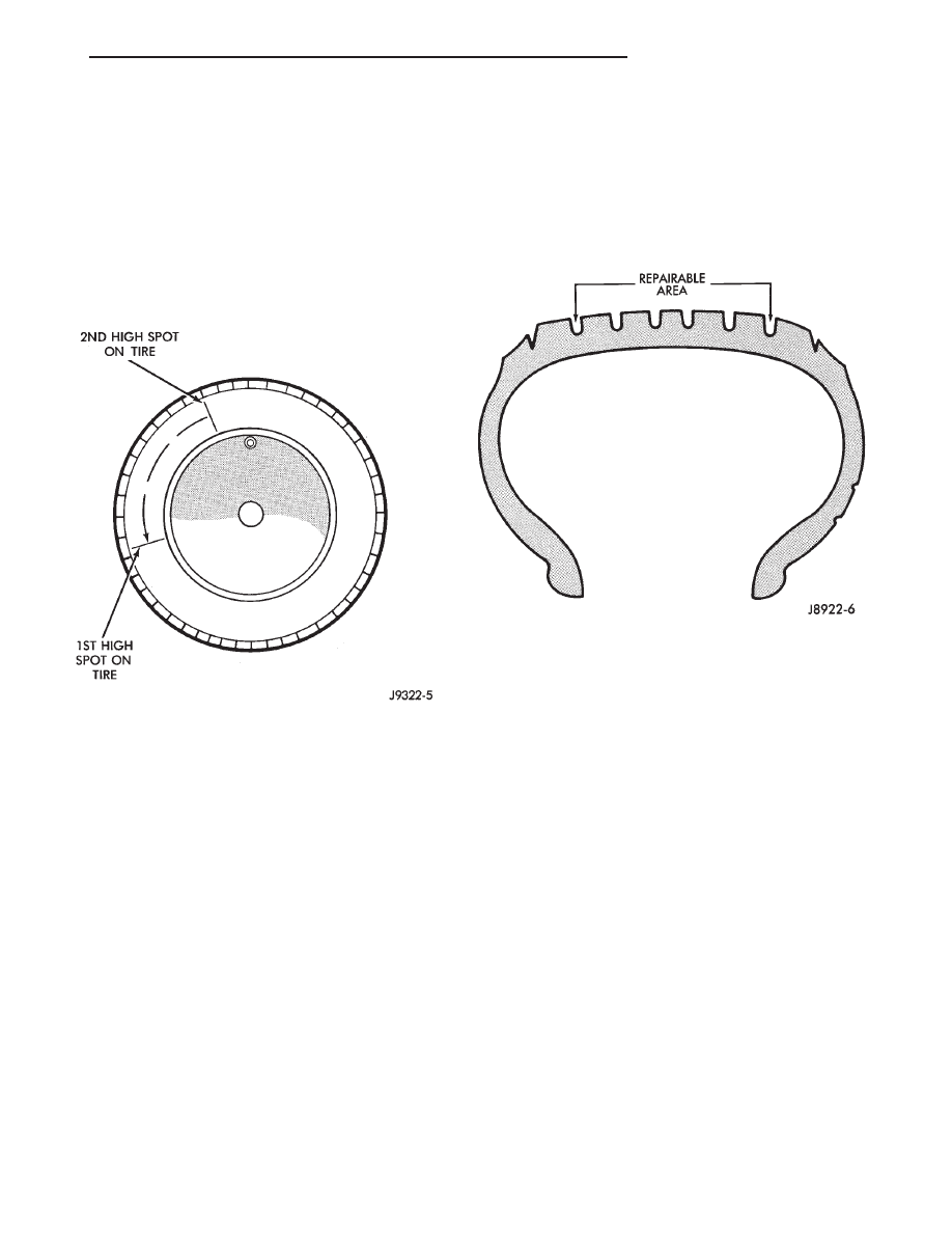
• If the high spot is within 101.6 mm (4.0 in.) of
the first spot and is still excessive, replace the tire.
• If the high spot is within 101.6 mm (4.0 in.) of
the first spot on the wheel, the wheel may be out of
specifications. Refer to Wheel and Tire Runout.
• If the high spot is NOT within 101.6 mm (4.0
in.) of either high spot, draw an arrow on the tread
from second high spot to first. Break down the tire
and remount it 90 degrees on rim in that direction
(Fig. 9). This procedure will normally reduce the
runout to an acceptable amount.
REPAIRING LEAKS
For proper repairing, a radial tire must be removed
from the wheel. Repairs should only be made if the
defect, or puncture, is in the tread area (Fig. 10). The
tire should be replaced if the puncture is located in
the sidewall.
Deflate tire completely before dismounting tire
from the wheel. Use lubrication such as a mild soap
solution when dismounting or mounting tire. Use
tools free of burrs or sharp edges which could dam-
age the tire or wheel rim.
Before mounting tire on wheel, make sure all rust
is removed from the rim bead and repaint if neces-
sary.
Install wheel on vehicle, and tighten to proper
torque specification.
CLEANING AND INSPECTION
CLEANING OF TIRES
Remove protective coating on tires before delivery
of vehicle. The coating could cause deterioration of
tires.
Remove protective coating by:
• Applying warm water
• Letting it soak one minute
• Scrubbing the coating away with a soft bristle
brush.
• Steam cleaning may also be used for cleaning.
• DO NOT use gasoline or wire brush for cleaning.
• DO NOT use mineral oil or an oil-based solvent.
Fig. 9 Remount Tire 90 Degrees In Direction of
Arrow
Fig. 10 Tire Repair Area
ZJ
TIRES AND WHEELS
22 - 7
SERVICE PROCEDURES (Continued)
WHEELS
INDEX
page
page
DESCRIPTION AND OPERATION
WHEEL . . . . . . . . . . . . . . . . . . . . . . . . . . . . . . . . 8
DIAGNOSIS AND TESTING
TIRE AND WHEEL RUNOUT . . . . . . . . . . . . . . . . 9
WHEEL INSPECTION . . . . . . . . . . . . . . . . . . . . . . 8
SERVICE PROCEDURES
TIRE AND WHEEL BALANCE . . . . . . . . . . . . . . . 10
WHEEL INSTALLATION . . . . . . . . . . . . . . . . . . . . 9
SPECIFICATIONS
TORQUE CHART . . . . . . . . . . . . . . . . . . . . . . . . 11
DESCRIPTION AND OPERATION
WHEEL
Available rim sizes are on the safety certification
label located on the drivers door shut face.
Rim size is determined by the drivetrain package.
Original equipment wheels are designed for opera-
tion up to the specified maximum vehicle capacity.
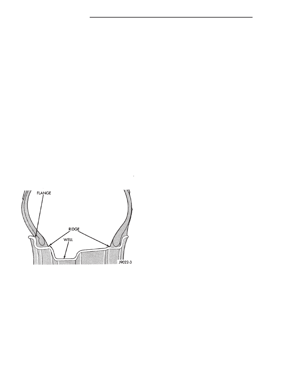
All models use steel or cast aluminum wheels. Every
wheel has raised sections between the rim flanges and
rim drop well called safety humps (Fig. 1).
Initial inflation of the tire forces the bead over
these raised sections. In case of tire failure, the
raised sections help hold the tire in position on the
wheel.
Cast aluminum wheels require coated balance
weights and special alignment equipment.
The wheel studs and nuts are designed for specific
applications and must be replaced with equivalent
parts. Do not use replacement parts of lesser quality
or a substitute design. All aluminum and some steel
wheels have wheel stud nuts with an enlarged nose.
This enlarged nose is necessary to ensure proper
retention of the wheels.
Before installing the wheel, remove any build up of
corrosion on the wheel mounting surfaces.
WARNING: INSTALLING WHEELS WITHOUT GOOD
METAL-TO-METAL CONTACT COULD CAUSE LOOS-
ENING OF WHEEL NUTS. THIS COULD ADVERSELY
AFFECT THE SAFETY AND HANDLING OF YOUR
VEHICLE.
DIAGNOSIS AND TESTING
WHEEL INSPECTION
Wheels must be replaced if they:
• Have excessive run out
• Are bent or dented
• Leak air
• Have damaged bolt holes
Wheel
repairs
employing
hammering,
heating,
welding or repairing leaks are not allowed.
Original equipment replacement wheels should be
used. When obtaining replacement wheels, they
should be equivalent in load carrying capacity. The
physical dimensions (diameter, width, offset, and bolt
circle) of the wheel should be the same as the origi-
nal wheel.
WARNING: FAILURE
TO
USE
EQUIVALENT
REPLACEMENT WHEELS MAY ADVERSELY AFFECT
THE SAFETY AND HANDLING OF THE VEHICLE.
REPLACEMENT WITH USED WHEELS IS NOT REC-
OMMENDED. THE SERVICE HISTORY OF THE RIM
MAY HAVE INCLUDED SEVERE TREATMENT OR
VERY HIGH MILEAGE. THE RIM COULD FAIL WITH-
OUT WARNING.
Fig. 1 Safety Rim
22 - 8
TIRES AND WHEELS
ZJ
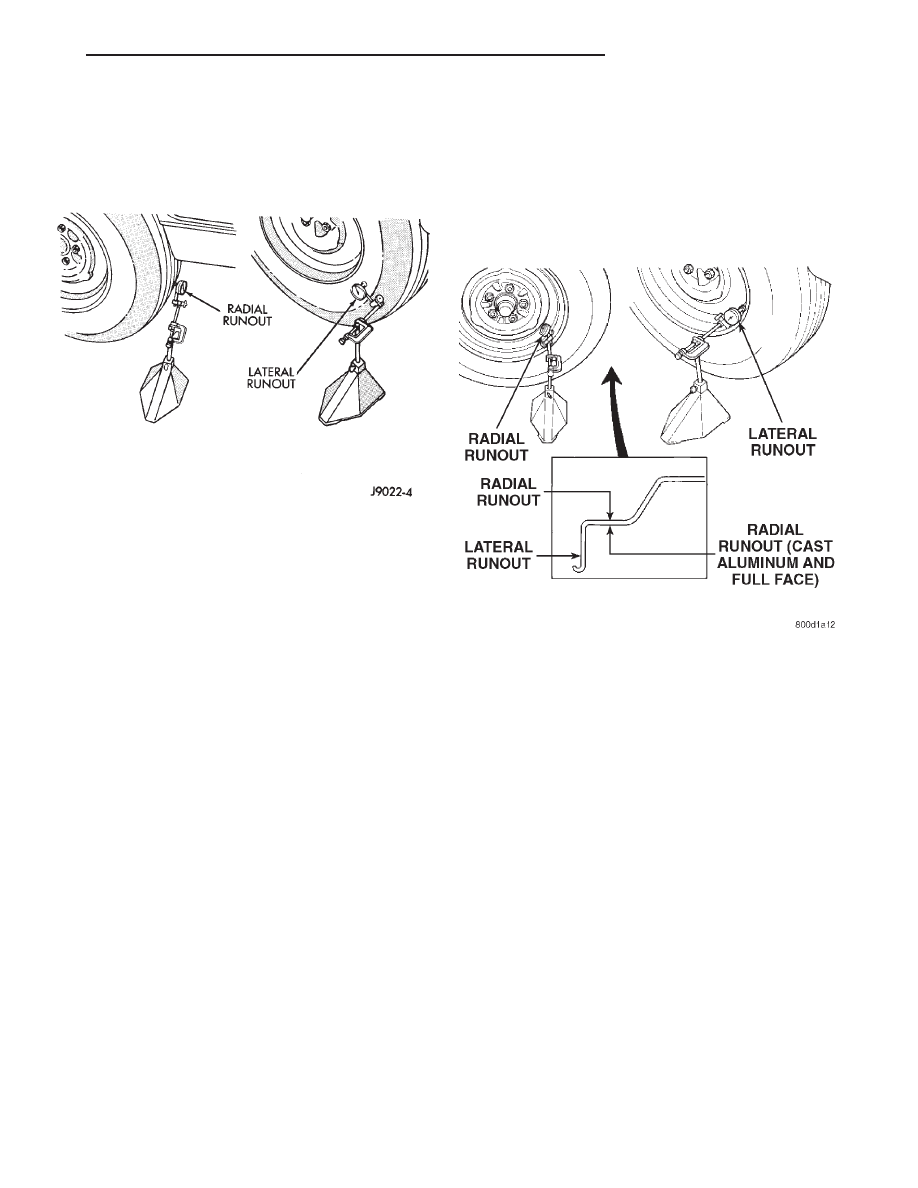
TIRE AND WHEEL RUNOUT
Radial runout is the difference between the high
and low points on the tire or wheel (Fig. 2).
Lateral runout is the wobble of the tire or wheel.
Radial runout of more than 1.5 mm (.060 inch)
measured at the center line of the tread may cause
the vehicle to shake.
Lateral runout of more than 2.0 mm (.080 inch)
measured near the shoulder of the tire may cause the
vehicle to shake.
Sometimes radial runout can be reduced. Relocate
the wheel and tire assembly on the mounting studs
(See Method 1). If this does not reduce runout to an
acceptable level, the tire can be rotated on the wheel.
(See Method 2).
METHOD 1 (RELOCATE WHEEL ON HUB)
Check accuracy of the wheel mounting surface;
adjust wheel bearings.
Drive vehicle a short distance to eliminate tire flat
spotting from a parked position.
Make sure all wheel nuts are properly torqued.
Relocate wheel on the mounting, two studs over
from the original position.
Re-tighten
wheel
nuts
until
all
are
properly
torqued, to eliminate brake distortion.
Check radial runout. If still excessive, mark tire
sidewall, wheel, and stud at point of maximum
runout and proceed to Method 2.
METHOD 2 (RELOCATE TIRE ON WHEEL)
Rotating tire on wheel is particularly effective
when there is runout in both tire and wheel.
Remove tire from wheel and re-mount wheel on
hub in former position.
Check wheel radial runout (Fig. 3).
NOTE: If the vehicle is equipped with aluminum or
full faced wheels the tire must be removed to check
radial runout.
• STEEL WHEELS: Radial runout 0.040 in., Lat-
eral runout 0.045 in.
• ALUMINUM WHEELS: Radial runout 0.030 in.,
Lateral runout 0.035 in.
If point of greatest runout is near original chalk
mark, remount tire 180 degrees. Recheck runout.
SERVICE PROCEDURES
WHEEL INSTALLATION
The wheel studs and nuts are designed for specific
applications. They must be replaced with equivalent
parts. Do not use replacement parts of lesser quality
or a substitute design. All aluminum and some steel
wheels have wheel stud nuts which feature an
enlarged nose. This enlarged nose is necessary to
ensure proper retention of the aluminum wheels.
NOTE: Do not use chrome plated lug nuts with
chrome plated wheels.
Before installing the wheel, be sure to remove any build
up of corrosion on the wheel mounting surfaces. Ensure
wheels are installed with good metal-to-metal contact.
Improper installation could cause loosening of wheel nuts.
This could affect the safety and handling of your vehicle.
To install the wheel, first position it properly on the
mounting surface. All wheel nuts should then be tightened
just snug. Gradually tighten them in sequence to the
Fig. 2 Checking Tire Runout
Fig. 3 Checking Wheel Runout
ZJ
TIRES AND WHEELS
22 - 9
DIAGNOSIS AND TESTING (Continued)
proper torque specification (Fig. 4). Never use oil or
grease on studs or nuts.
WHEEL REPLACEMENT
Wheels must be replaced if they have:
• Excessive runout
• Bent or dented
• Leak air through welds
• Have damaged bolt holes
Wheel repairs employing hammering, heating, or
welding are not allowed.
Original equipment wheels are available through
your dealer. Replacement wheels from any other
source should be equivalent in:
• Load carrying capacity
• Diameter
• Width
• Offset
• Mounting configuration
Failure to use equivalent replacement wheels may affect
the safety and handling of your vehicle. Replacement with
used wheels is not recommended. Their service his-
tory may have included severe treatment.
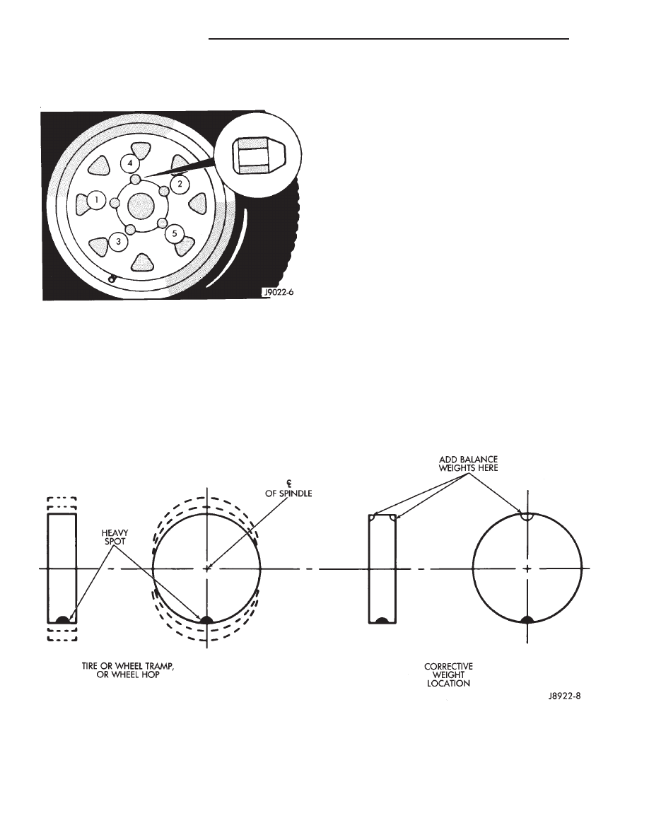
TIRE AND WHEEL BALANCE
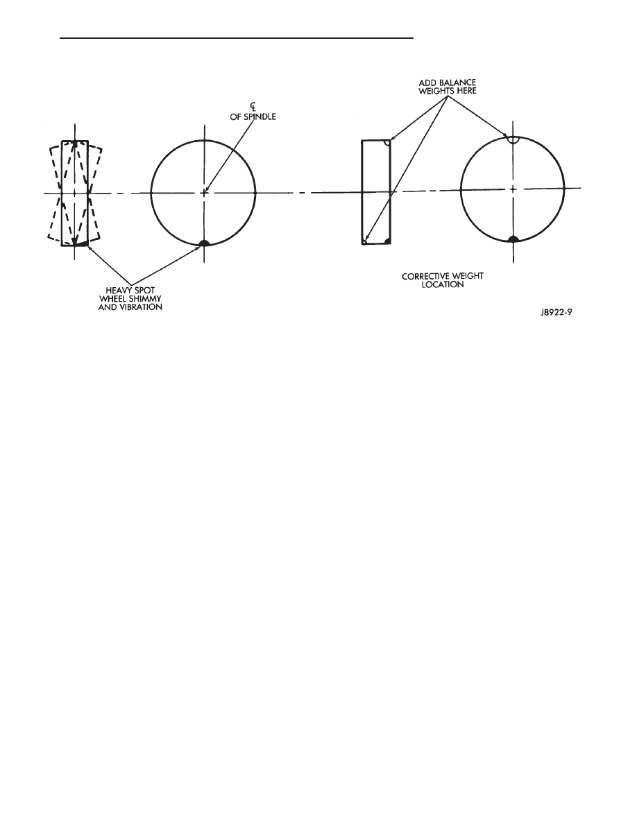
It is recommended that a two plane dynamic bal-
ancer be used when a wheel and tire assembly
require balancing. Static should be used only when a
two plane balancer is not available.
For static imbalance, find location of heavy spot
causing imbalance. Counter balance wheel directly
opposite the heavy spot. Determine weight required
to counterbalance the area of imbalance. Place half of
this weight on the inner rim flange and the other
half on the outer rim flange (Fig. 5) and (Fig. 6).
Off-vehicle balancing is necessary.
Wheel balancing can be accomplished with either
on or off vehicle equipment. When using on-vehicle
balancing equipment, remove the opposite wheel/tire.
Fig. 5 Static Unbalance & Balance
Fig. 4 Lug Nut Tightening Pattern
22 - 10
TIRES AND WHEELS
ZJ
SERVICE PROCEDURES (Continued)
SPECIFICATIONS
TORQUE CHART
DESCRIPTION
TORQUE
Lug Nut
1/2 X 20 with 60° Cone . . . . . . . . . .109 to 150 N·m
(80 to 110 ft. lbs.)
Fig. 6 Dynamic Unbalance & Balance
ZJ
TIRES AND WHEELS
22 - 11

Document Outline
- TIRES AND WHEELS
Wyszukiwarka
Podobne podstrony:
M32e Tires and Wheels
ISO128 22 leader and reference lines
ISO128 22 leader and reference lines
Edgar Rice Burroughs Tarzan 22 Tarzan and the Foreign Legiion
22 Phonetics and Historical Phonology
96ZJ 8K WIPER AND WASHER SYSTEMS
part3 22 Pragmatics and the Lexicon
96ZJ 13 FRAME AND BUMPERS
93ZJ Secc 22 Wheels and Tires
extraction and analysis of indole derivatives from fungal biomass Journal of Basic Microbiology 34 (
Wheels and truing
22 The climate of Polish Lands as viewed by chroniclers, writers and scientists
22)20 09 Present continuous questions and answers IVa
Fundamentals of Anatomy and Physiology 22 Chapter
96ZJ 11 EXHAUST SYSTEM AND INTAKE MANIFOLD
FIDE Trainers Surveys 2013 05 22, Karsten Müller Endgames with Rook and minor piece against Rook an
96ZJ 0 LUBRICATION AND MAINTENANCE
więcej podobnych podstron