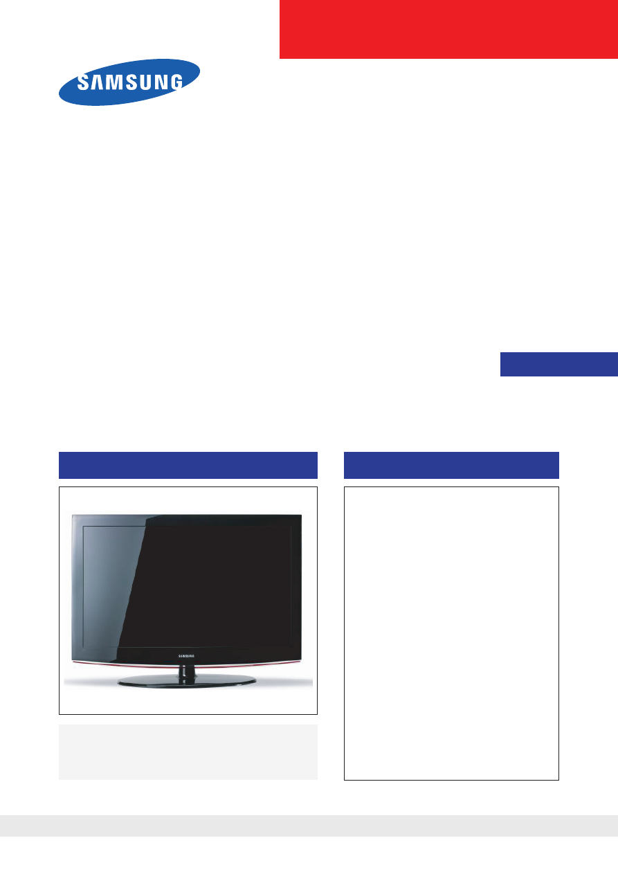
LCD-TV
Chassis :N65C
Model
:LE26B450C4H
LE32B450C4H
LE26B457C6H
LE32B457C6H
LE37B457C6H
SERVICE
Manual
TFT-LCD TV
Contents
LE26B450C4H/LE26B457C6H
LE32B450C4H/LE32B457C6H/
LE37B457C6H
Refer to the service manual in the GSPN (see the rear cover) for the more information.
1.Precautions
2. Product specifications
3.DisassemblyandReassembly
4.Troubleshooting
5.ExplodedView&PartList
6.WiringDiagram

Contents
1.Precautions.............................................................................................................. 1-1
1-1. Safety Precautions ......................................................................................................... 1-1
1-2. Servicing Precautions ..................................................................................................... 1-2
1-3. Electrostatically Sensitive Devices (ESD) Precautions .................................................. 1-2
1-4. Installation Precautions .................................................................................................. 1-3
2. Product specifications............................................................................................ 2-1
2-1. Feature & Specifications ................................................................................................. 2-1
2-2. New Features explanation .............................................................................................. 2-7
2-3. Specification Comparison to Old Models ........................................................................ 2-8
2-4. Accessories .................................................................................................................... 2-9
3.DisassemblyandReassembly............................................................................... 3-1
3-1. Disassembly and Reassembly ....................................................................................... 3-1
4.Troubleshooting...................................................................................................... 4-1
4-1. Troubleshooting .............................................................................................................. 4-1
4-2. Alignments and Adjustments ........................................................................................ 4-25
4-3. Factory Mode Adjustments ........................................................................................... 4-26
4-4. White Balance - Calibration .......................................................................................... 4-38
4-5. White Ratio (Balance) Adjustment ................................................................................ 4-38
4-6. Servicing Information .................................................................................................... 4-39
4-7. HOW TO UPGRADE WITH JIG ................................................................................... 4-40
4-8. PCB diagram ................................................................................................................ 4-42
5.ExplodedView&PartList...................................................................................... 5-1
5-1. LE26B450C4H / LE26B457C6H Exploded View ............................................................ 5-1
5-2. LE32B450C4H / LE32B457C6H Exploded View ............................................................ 5-3
5-3. LE37B457C6H Exploded View ....................................................................................... 5-5
5-4. LE26B45*C4H Parts List ................................................................................................ 5-9
5-5. LE32B45*C4H Parts List .............................................................................................. 5-32
5-6. LE37B45*C4H Parts List .............................................................................................. 5-55
6.WiringDiagram........................................................................................................ 6-1
6-1. Wiring Diagram 26”/32”/37” ............................................................................................ 6-1
6-2. Connector Functions ...................................................................................................... 6-5
6-3. Cables ............................................................................................................................ 6-5
GSPN(GlobalServicePartnerNetwork)
Area
WebSite
NorthAmerica
http://service.samsungportal.com
LatinAmerica
http://latin.samsungportal.com
CIS
http://cis.samsungportal.com
Europe
http://europe.samsungportal.com
China
http://china.samsungportal.com
Asia
http://asia.samsungportal.com
Mideast&Africa
http://mea.samsungportal.com
ThisServiceManualisapropertyofSamsungElectronicsCo.,Ltd.
Any unauthorized use of Manual can be punished under applicable
International and/or domestic law.
©2009SamsungElectronicsCo.,Ltd.
Allrightsreserved.
Printed in Korea
P/N: BN82-00595A-00
Wyszukiwarka
Podobne podstrony:
Samsung CK5038 chassis SCT11B
Samsung chassis P58SAT (CDH236)
OTVC SAMSUNG CB536ZSE chassis P54S
philips chassis l6 1
A1CS EG24A GETZ 2003 CHASSIS BR
A1CS EG24A GETZ 2003 CHASSIS EC układ emisji spalin
5 Chassis
Burj Khalifa Monitoring Program (wg SAMSUNGa)
A1CS EG24A GETZ 2003 CHASSIS FL
A1CS EG24A GETZ 2003 CHASSIS TR
kody błędów do pralek samsung (PL)
Philips G6 Tv Chassis
8T84 CHASSIS SERVICE MANUAL
A1CS EG24A GETZ 2003 CHASSIS ST
18617 dr chassis sgmldiag
Zenith B1 Chassis
Piaggio Ape Chassis Numbers
Instrukcja obslugi telefonu SAMSUNG C3050 PL
Panasonic chassis EURO 3 MX3
więcej podobnych podstron