
TABLE OF CONTENTS
INTRODUCTION . . . . . . . . . . . . . . . . . . . . . . . . . . . . . . . . . . . . . . . . . . . . . . . . . . . . . . . . .1
SYSTEM COVERAGE . . . . . . . . . . . . . . . . . . . . . . . . . . . . . . . . . . . . . . . . . . . . . . .1
SIX-STEP TROUBLESHOOTING PROCEDURE . . . . . . . . . . . . . . . . . . . . . . . . . .1
IDENTIFICATION OF SYSTEM . . . . . . . . . . . . . . . . . . . . . . . . . . . . . . . . . . . . . . . . . . . . .1
SYSTEM DESCRIPTION AND FUNCTIONAL OPERATION . . . . . . . . . . . . . . . . . . . . . .1
ABS . . . . . . . . . . . . . . . . . . . . . . . . . . . . . . . . . . . . . . . . . . . . . . . . . . . . . . . . . . . . . .1
TRW EBC 125 SYSTEM DESCRIPTION . . . . . . . . . . . . . . . . . . . . . . . .2
TRW EBC 325 SYSTEM DESCRIPTION . . . . . . . . . . . . . . . . . . . . . . . .2
TRW EBC 125 CONTROLLER ANTILOCK BRAKE (CAB). . . . . . . . . . .2
TRW EBC 325 CONTROLLER ANTILOCK BRAKE (CAB). . . . . . . . . . .3
ABS WARNING INDICATOR AND RED BRAKE WARNING
INDICATOR (EBC 125 AND EBC 325) . . . . . . . . . . . . . . . . . . . . . . . . . .3
BRAKE LAMP SWITCH CIRCUIT . . . . . . . . . . . . . . . . . . . . . . . . . . . . . .4
BRAKE FLUID LEVEL SWITCH CIRCUIT . . . . . . . . . . . . . . . . . . . . . . . .4
HYDRAULIC CONTROL UNIT . . . . . . . . . . . . . . . . . . . . . . . . . . . . . . . . .4
WHEEL SPEED SENSORS . . . . . . . . . . . . . . . . . . . . . . . . . . . . . . . . . . .4
4WD INPUT . . . . . . . . . . . . . . . . . . . . . . . . . . . . . . . . . . . . . . . . . . . . . . . .5
DIAGNOSTIC COMMAND MODES . . . . . . . . . . . . . . . . . . . . . . . . . . . . .5
SELF-TEST AT IGNITION TURN ON. . . . . . . . . . . . . . . . . . . . . . . . . . . .5
DIAGNOSTIC COMMANDS . . . . . . . . . . . . . . . . . . . . . . . . . . . .6
THE ON-BOARD DIAGNOSTIC SYSTEM. . . . . . . . . . . . . . . . . . . . . . . .6
ADJUSTABLE PEDALS SYSTEM . . . . . . . . . . . . . . . . . . . . . . . . . . . . . . . . . . . . . .6
GENERAL . . . . . . . . . . . . . . . . . . . . . . . . . . . . . . . . . . . . . . . . . . . . . . . . .6
ADJUSTABLE PEDALS RELAY . . . . . . . . . . . . . . . . . . . . . . . . . . . . . . . .6
. . . . . . . . . . . . . . . . . . . . . . . . . . . . . . . . . . . . . . . . . . . . . . . . .6
ERROR MESSAGES AND BLANK SCREEN . . . . . . . . . . . . . . . . . . . . . .6
DOES NOT POWER UP. . . . . . . . . . . . . . . . . . . . . . . . . . . . . . .7
DISPLAY IS NOT VISIBLE . . . . . . . . . . . . . . . . . . . . . . . . . . . . . . . . . . . .7
DISCLAIMERS, SAFETY, WARNINGS . . . . . . . . . . . . . . . . . . . . . . . . . . . . . . . . . . . . . . .7
DISCLAIMERS. . . . . . . . . . . . . . . . . . . . . . . . . . . . . . . . . . . . . . . . . . . . . . . . . . . . . .7
SAFETY . . . . . . . . . . . . . . . . . . . . . . . . . . . . . . . . . . . . . . . . . . . . . . . . . . . . . . . . . . .7
TECHNICIAN SAFETY INFORMATION . . . . . . . . . . . . . . . . . . . . . . . . . .7
VEHICLE PREPARATION FOR TESTING. . . . . . . . . . . . . . . . . . . . . . . .7
SERVICING SUB-ASSEMBLIES . . . . . . . . . . . . . . . . . . . . . . . . . . . . . . .7
SAFETY INFORMATION. . . . . . . . . . . . . . . . . . . . . . . . . . . . . . .7
WARNINGS . . . . . . . . . . . . . . . . . . . . . . . . . . . . . . . . . . . . . . . . . . . . . . . . . . . . . . . .8
VEHICLE DAMAGE WARNINGS . . . . . . . . . . . . . . . . . . . . . . . . . . . . . . .8
ROAD TESTING A COMPLAINT VEHICLE . . . . . . . . . . . . . . . . . . . . . . .8
DIAGNOSIS . . . . . . . . . . . . . . . . . . . . . . . . . . . . . . . . . . . . . . . . . . . . . . . . . . . . . . . .8
REQUIRED TOOLS AND EQUIPMENT . . . . . . . . . . . . . . . . . . . . . . . . . . . . . . . . . . . . . .9
GLOSSARY OF TERMS. . . . . . . . . . . . . . . . . . . . . . . . . . . . . . . . . . . . . . . . . . . . . . . . . . .9
i

TABLE OF CONTENTS - Continued
DIAGNOSTIC INFORMATION AND PROCEDURES . . . . . . . . . . . . . . . . . . . . . . . . . . .11
ADJUSTABLE PEDALS
APS RELAY CONTROL CIRCUIT HIGH . . . . . . . . . . . . . . . . . . . . . . . . . . . . . . . . . . . . .12
APS RELAY CONTROL CIRCUIT LOW. . . . . . . . . . . . . . . . . . . . . . . . . . . . . . . . . . . . . .14
APS RELAY CONTROL CIRCUIT OPEN. . . . . . . . . . . . . . . . . . . . . . . . . . . . . . . . . . . . .16
BRAKES (CAB)
BODY STYLE MISMATCH - 85 . . . . . . . . . . . . . . . . . . . . . . . . . . . . . . . . . . . . . . . . . . . .18
BRAKE SWITCH CIRCUIT - 81 . . . . . . . . . . . . . . . . . . . . . . . . . . . . . . . . . . . . . . . . . . . .19
ECU INTERNAL FAILURE - 75 . . . . . . . . . . . . . . . . . . . . . . . . . . . . . . . . . . . . . . . . . . . .21
EXCESSIVE DUMP TIME - 69 . . . . . . . . . . . . . . . . . . . . . . . . . . . . . . . . . . . . . . . . . . . . .22
FOUNDATION BRAKE - 78 . . . . . . . . . . . . . . . . . . . . . . . . . . . . . . . . . . . . . . . . . . . . . . .24
INTERMITTENT SIGNAL FROM LEFT FRONT SENSOR - 27 . . . . . . . . . . . . . . . . . . .26
INTERMITTENT SIGNAL FROM REAR SENSOR - 37 . . . . . . . . . . . . . . . . . . . . . . . . .26
INTERMITTENT SIGNAL FROM RIGHT FRONT SENSOR - 23 . . . . . . . . . . . . . . . . . .26
LEFT FRONT SENSOR OPEN - 25. . . . . . . . . . . . . . . . . . . . . . . . . . . . . . . . . . . . . . . . .26
LEFT FRONT SENSOR SHORTED - 90 . . . . . . . . . . . . . . . . . . . . . . . . . . . . . . . . . . . . .26
NO SIGNAL FROM LEFT FRONT SENSOR - 26 . . . . . . . . . . . . . . . . . . . . . . . . . . . . . .26
NO SIGNAL FROM REAR SENSOR - 36 . . . . . . . . . . . . . . . . . . . . . . . . . . . . . . . . . . . .26
NO SIGNAL FROM RIGHT FRONT SENSOR - 22. . . . . . . . . . . . . . . . . . . . . . . . . . . . .26
REAR SENSOR OPEN - 35 . . . . . . . . . . . . . . . . . . . . . . . . . . . . . . . . . . . . . . . . . . . . . . .26
REAR SENSOR SHORTED - 93 . . . . . . . . . . . . . . . . . . . . . . . . . . . . . . . . . . . . . . . . . . .26
RIGHT FRONT SENSOR OPEN - 21 . . . . . . . . . . . . . . . . . . . . . . . . . . . . . . . . . . . . . . .26
RIGHT FRONT SENSOR SHORTED - 91. . . . . . . . . . . . . . . . . . . . . . . . . . . . . . . . . . . .26
INTERNAL MAIN RELAY OPEN - 65. . . . . . . . . . . . . . . . . . . . . . . . . . . . . . . . . . . . . . . .32
INTERNAL MAIN RELAY SHORTED - 66 . . . . . . . . . . . . . . . . . . . . . . . . . . . . . . . . . . . .34
LEFT FRONT DUMP SOLENOID OPEN - 46 . . . . . . . . . . . . . . . . . . . . . . . . . . . . . . . . .36
LEFT FRONT DUMP SOLENOID SHORTED - 48 . . . . . . . . . . . . . . . . . . . . . . . . . . . . .36
LEFT FRONT ISOLATION SOLENOID OPEN - 45. . . . . . . . . . . . . . . . . . . . . . . . . . . . .36
LEFT FRONT ISOLATION SOLENOID SHORTED - 47 . . . . . . . . . . . . . . . . . . . . . . . . .36
REAR DUMP SOLENOID OPEN - 52 . . . . . . . . . . . . . . . . . . . . . . . . . . . . . . . . . . . . . . .36
REAR DUMP SOLENOID SHORTED - 54 . . . . . . . . . . . . . . . . . . . . . . . . . . . . . . . . . . .36
REAR ISOLATION SOLENOID OPEN - 51 . . . . . . . . . . . . . . . . . . . . . . . . . . . . . . . . . . .36
REAR ISOLATION SOLENOID SHORTED - 53 . . . . . . . . . . . . . . . . . . . . . . . . . . . . . . .36
RIGHT FRONT DUMP SOLENOID OPEN - 42. . . . . . . . . . . . . . . . . . . . . . . . . . . . . . . .36
RIGHT FRONT DUMP SOLENOID SHORTED - 44 . . . . . . . . . . . . . . . . . . . . . . . . . . . .36
RIGHT FRONT ISOLATION SOLENOID OPEN - 41 . . . . . . . . . . . . . . . . . . . . . . . . . . .36
RIGHT FRONT ISOLATION SOLENOID SHORTED - 43. . . . . . . . . . . . . . . . . . . . . . . .36
MISMATCHED VIN - 84 . . . . . . . . . . . . . . . . . . . . . . . . . . . . . . . . . . . . . . . . . . . . . . . . . .40
NUMBER OF TONE RING TEETH OUT OF RANGE - 82 . . . . . . . . . . . . . . . . . . . . . . .41
PUMP MOTOR CIRCUIT OPEN - 67. . . . . . . . . . . . . . . . . . . . . . . . . . . . . . . . . . . . . . . .42
PUMP MOTOR STALLED - 68 . . . . . . . . . . . . . . . . . . . . . . . . . . . . . . . . . . . . . . . . . . . . .42
RAM READ/WRITE - 71 . . . . . . . . . . . . . . . . . . . . . . . . . . . . . . . . . . . . . . . . . . . . . . . . . .46
REAR RESET SWITCH CLOSED - 63 . . . . . . . . . . . . . . . . . . . . . . . . . . . . . . . . . . . . . .47
ROM CHECKSUM - 72 . . . . . . . . . . . . . . . . . . . . . . . . . . . . . . . . . . . . . . . . . . . . . . . . . . .48
SYSTEM CONTROL MODE TIMEOUT - 74 . . . . . . . . . . . . . . . . . . . . . . . . . . . . . . . . . .49
SYSTEM OVER / UNDER VOLTAGE - 96 . . . . . . . . . . . . . . . . . . . . . . . . . . . . . . . . . . .52
TIRE REVS PER MILE OUT OF RANGE - 83 . . . . . . . . . . . . . . . . . . . . . . . . . . . . . . . .53
WATCHDOG - 73 . . . . . . . . . . . . . . . . . . . . . . . . . . . . . . . . . . . . . . . . . . . . . . . . . . . . . . .54
WHEEL SPEED MISMATCH - 38. . . . . . . . . . . . . . . . . . . . . . . . . . . . . . . . . . . . . . . . . . .56
*REPLACING THE CONTROLLER ANTILOCK BRAKE . . . . . . . . . . . . . . . . . . . . . . . . .57
*VEHICLE SPEED SIGNAL OUTPUT . . . . . . . . . . . . . . . . . . . . . . . . . . . . . . . . . . . . . . .59
ii

TABLE OF CONTENTS - Continued
COMMUNICATION
*NO RESPONSE FROM CONTROLLER ANTILOCK BRAKE . . . . . . . . . . . . . . . . . . . .61
VERIFICATION TESTS
VERIFICATION TESTS . . . . . . . . . . . . . . . . . . . . . . . . . . . . . . . . . . . . . . . . . . . . . . . . . . .63
COMPONENT LOCATIONS . . . . . . . . . . . . . . . . . . . . . . . . . . . . . . . . . . . . . . . . . . . . . . .65
CONTROLLER ANTILOCK BRAKE (CAB) . . . . . . . . . . . . . . . . . . . . . . . . . . . . . .65
EBC 125 (RWAL) . . . . . . . . . . . . . . . . . . . . . . . . . . . . . . . . . . . . . . . . . .65
EBC 325 (ABS) . . . . . . . . . . . . . . . . . . . . . . . . . . . . . . . . . . . . . . . . . . . .65
DATA LINK CONNECTOR . . . . . . . . . . . . . . . . . . . . . . . . . . . . . . . . . . . . . . . . . . .65
WHEEL SPEED SENSORS/TONE WHEELS . . . . . . . . . . . . . . . . . . . . . . . . . . . .66
FRONT. . . . . . . . . . . . . . . . . . . . . . . . . . . . . . . . . . . . . . . . . . . . . . . . . . .66
REAR . . . . . . . . . . . . . . . . . . . . . . . . . . . . . . . . . . . . . . . . . . . . . . . . . . . .66
FRONT WHEEL SPEED SENSOR CONNECTOR . . . . . . . . . . . . . . . . . . . . . . . .66
REAR WHEEL SPEED SENSOR CONNECTOR . . . . . . . . . . . . . . . . . . . . . . . . .67
BRAKE LAMP SWITCH . . . . . . . . . . . . . . . . . . . . . . . . . . . . . . . . . . . . . . . . . . . . .67
BRAKE FLUID LEVEL SWITCH . . . . . . . . . . . . . . . . . . . . . . . . . . . . . . . . . . . . . . .67
ADJUSTABLE PEDAL SWITCH . . . . . . . . . . . . . . . . . . . . . . . . . . . . . . . . . . . . . . .68
CONNECTOR PINOUTS . . . . . . . . . . . . . . . . . . . . . . . . . . . . . . . . . . . . . . . . . . . . . . . . .69
ABS PUMP MOTOR CONNECTOR - 2 WAY . . . . . . . . . . . . . . . . . . . . . . . . . . . . . . . . .69
ADJUSTABLE PEDAL MOTOR (EXCEPT MEMORY) - 2 WAY . . . . . . . . . . . . . . . . . . .69
ADJUSTABLE PEDAL SWITCH (EXCEPT MEMORY) - BLUE 6 WAY . . . . . . . . . . . . .69
BRAKE FLUID LEVEL SWITCH - BLACK 2 WAY . . . . . . . . . . . . . . . . . . . . . . . . . . . . . .69
BRAKE LAMP SWITCH - 6 WAY . . . . . . . . . . . . . . . . . . . . . . . . . . . . . . . . . . . . . . . . . . .70
CONTROLLER ANITLOCK BRAKE C1 - BLACK 14 WAY . . . . . . . . . . . . . . . . . . . . . . .70
CONTROLLER ANTILOCK BRAKE C2 (ABS) - BLACK 4 WAY . . . . . . . . . . . . . . . . . .70
DATA LINK CONNECTOR - BLACK 16 WAY . . . . . . . . . . . . . . . . . . . . . . . . . . . . . . . . .71
ADJUSTABLE PEDAL RELAY . . . . . . . . . . . . . . . . . . . . . . . . . . . . . . . . . . . . . . . . . . . . .73
WHEEL SPEED SENSOR-LEFT FRONT - 2 WAY . . . . . . . . . . . . . . . . . . . . . . . . . . . . .73
WHEEL SPEED SENSOR-REAR - 2 WAY . . . . . . . . . . . . . . . . . . . . . . . . . . . . . . . . . . .73
WHEEL SPEED SENSOR-RIGHT FRONT - 2 WAY . . . . . . . . . . . . . . . . . . . . . . . . . . . .73
SCHEMATIC DIAGRAMS. . . . . . . . . . . . . . . . . . . . . . . . . . . . . . . . . . . . . . . . . . . . . . . . .75
10.1 TRW EBC 125 – CONTROLLER ANTILOCK BRAKE . . . . . . . . . . . . . . . . . . . . .75
10.2 TRW EBC 325 – CONTROLLER ANTILOCK BRAKE . . . . . . . . . . . . . . . . . . . . .76
10.3 ADJUSTABLE PEDAL RELAY . . . . . . . . . . . . . . . . . . . . . . . . . . . . . . . . . . . . . . . .77
iii

NOTES
iv

1.0
INTRODUCTION
The procedures contained in this manual include
all the specifications, instructions, and graphics
needed to diagnose the DR Chassis system prob-
lems: TRW EBC 125 Rear Wheel Antilock (RWAL)
and EBC 325 Antilock Braking System (ABS) and
the Adjustable Pedals System (APS). The diagnos-
tics in this manual are based on the failure condi-
tion or symptom being present at time of diagnosis.
Please follow the recommendations below when
choosing your diagnostic path.
1. First make sure the DRBIII
t is communicating
with the vehicle system being diagnosed. If the
DRBIII
t displays a “No Response” condition, you
must diagnose that first.
2. Read DTC’s (diagnostic trouble codes) with the
DRBIII
t.
3. If no DTC’s are present, identify the customer
complaint.
4. Once the DTC or customer complaint is identi-
fied locate the matching test in the Table of
Contents and begin to diagnose the system.
All component location views are in Section 8.0.
All connector pinouts are in Section 9.0. All sche-
matics are in Section 10.0.
An asterisk (*) placed before the symptom de-
scription indicates a customer complaint.
When repairs are required, refer to the appropri-
ate service manual for the proper removal and
repair procedure.
Diagnostic procedures change every year. New
diagnostic systems may be added; carryover sys-
tems may be enhanced. READ THIS MANUAL
BEFORE TRYING TO DIAGNOSE A VEHICLE
DIAGNOSTIC TROUBLE CODE. It is recom-
mended that you review the entire manual to be-
come familiar with all new and changed diagnostic
procedures.
This manual reflects many suggested changes
from readers of past issues. After using this man-
ual, if you have any comments or recommendations,
please fill out the form at the back of the book and
mail it back to us.
1.1
SYSTEM COVERAGE
There are two antilock systems used on these
trucks: the TRW EBC 125 and EBC 325. EBC 125
(RWAL) is standard, two-wheel rear wheel antilock
braking system.
EBC 325 (ABS) is optional, four-wheel antilock
braking system.
Diagnosis of certain Front Control Module (FCM)
diagnostic trouble code (DTC) related to the
Adjustable Pedals System (APS) relay (if equipped)
is covered in this manual.
1.2
SIX-STEP TROUBLESHOOTING
PROCEDURE
Diagnosis of the antilock brake systems and the
adjustable pedal system is done in six basic steps:
•
Verification of complaint
•
Verification of any related symptoms
•
Symptom analysis
•
Problem isolation
•
Repair of isolated problem
•
Verification of proper operation
2.0
IDENTIFICATION OF
SYSTEM
The EBC 125 is a one channel, one HCU, to
control hydraulic pressure to both REAR brakes
during antilock braking, and one rear wheel speed
sensor. EBC 125 for 5.7L will have pins for left front
sensor and second vehicle speed signals to NGC.
However there is no diagnostics provided for this
signal in the EBC 125 module. A CAB mounted on
top of the HCU controls the solenoids/valves.
The EBC 325 is a three channel, one HCU to
control the FRONT and REAR brakes, two front
wheel speed sensors, and one rear wheel speed
sensor. The CAB mounted on the top of the HCU
controls the solenoids/values.
Vehicles equipped with the Adjustable Pedal Sys-
tem (APS) can be identified by the presence of the
Adjustable Pedals switch located to the left of the
steering column below the headlamp switch.
3.0
SYSTEM DESCRIPTION AND
FUNCTIONAL OPERATION
3.1
ABS
The controller-antilock (CAB) is used to monitor
wheel speeds and modulates (control) hydraulic
pressure in each brake channel. The modulated
hydraulic pressure is used to prevent wheel lock up
during braking and maintain vehicle stability. The
CAB also provides a vehicle speed signal (VSS) to
the powertrain control module.
During a non-ABS stop, the system functions as a
standard front/rear split configuration. The pri-
mary supplies brake fluid pressure to the front
brakes, and the secondary supplies the rear brakes.
The CAB has a special software program called
Electronic Variable Brake Proportioning (EVBP),
that monitors the wheel speed(s) and when certain
criteria are met the software will enable the HCU to
1
GENERAL INFORMATION

perform the same brake fluid management control
as the combination/proportioning valves.
The EBC 125 (RWAL) system uses Electronic
Brake Apportioning (EBA). The HCU replaces the
conventional proportioning valve as a means of
balancing the front-to-rear breaking effort under
normal braking conditions.
EBA makes more effective use of the rear brakes
when the truck is lightly loaded, balancing front-to-
rear lining wear and minimizing instances of rear
wheel antilock action. As with a proportioning
valve, EBA uses the rear axle speed sensor to
determine how much, if any, to reduce the rear
brake hydraulic pressure based on the deceleration
of the rear wheels. EBA automatically adapts to
variations in the vehicle loading and road surface,
where as a proportioning valve is fixed.
The EBC 325 (ABS) system uses Dynamic Rear
Proportioning (DRP). Like EBA on the RWAL sys-
tem, the HCU replaces the conventional proportion-
ing valve as means of balancing the front-to-rear
braking effort under normal braking conditions.
Unlike EBA, DRP adjusts hydraulic pressure to the
rear brakes based on the amount of slip indicated
by the wheel speed sensors when in activation.
Both EBC 125 (RWAL) and EBC 325 (ABS) use
the CAB and HCU to make an integral electronic/
hydraulic unit which shares data with other elec-
tronic modules on the vehicle via the PCI BUS
network.
During an RWAL stop, the system still uses the
front/rear hydraulic split; however, the brake sys-
tem pressure is further split into one control chan-
nel. During RWAL operation, the front wheels are
not assisted and brake pressure is applied from the
master cylinder, while the rear wheels are con-
trolled together through one channel by the HCU.
During an ABS stop, the system still uses the
front/rear hydraulic split; however, the brake sys-
tem pressure is further split into three controls
channels. During ABS operation, the front wheels
are controlled independently and are on two sepa-
rate control channels. The rear wheels are con-
trolled together through one channel. By using
separate control channels for the front wheels, more
steering control is maintained during maximum
braking.
During an antilock stop, “wheel lock-up” doesn’t
necessarily mean that the wheel has locked, it
means only that the wheel is turning slower than
the vehicle speed. This is called “wheel slip” and is
indicated as a percentage. 0% slip means that the
wheel is rolling free and 100% slip means that the
wheel is locked. The antilock system maintains an
average of approximately 20% wheel slip.
3.1.1
TRW EBC 125 SYSTEM
DESCRIPTION
The EBC 125 (RWAL) system can be identified by
the controller-antilock brake (CAB) and hydraulic
control unit (HCU) being an integral electronic/
hydraulic unit. One 14 way connector and mounted
near the master cylinder next to the battery tray.
SYSTEM COMPONENTS - TRW EBC 125
•
Controller antilock brake (CAB)
•
Hydraulic control unit (HCU)
•
One wheel speed sensor/tone wheel assembly in
rear axle
•
Left front wheel speed sensor (5.7L only)
•
ABS warning indicator (amber)
•
Brake warning indicator (red)
•
Brake fluid level switch
•
4WD input (if equipped)
•
Brake lamp switch
•
Fuses and wiring
3.1.2
TRW EBC 325 SYSTEM
DESCRIPTION
The EBC 325 (ABS) system can be identified by
the controller-antilock brake (CAB) and hydraulic
control unit (HCU) being an integral electronic/
hydraulic unit with a pump/motor unit. One 14-way
connector, one 4 way connector and mounted under
the hood in close proximity to the master cylinder
next to the battery tray.
SYSTEM COMPONENTS - TRW EBC 325
•
Controller antilock brake (CAB)
•
Hydraulic control unit (HCU)
•
Three wheel speed sensor/tone wheel assemblies
•
ABS warning indicator (amber)
•
Brake warning indicator (red)
•
Brake fluid level switch
•
4WD input (if equipped)
•
Brake lamp switch
•
Fuses and wiring
3.1.3
TRW EBC 125 CONTROLLER
ANTILOCK BRAKE (CAB)
The CAB is mounted directly to the hydraulic
control unit (HCU) that includes a microprocessor
and two solenoids that control the valves that
control brake pressure during RWAL braking and
circuits that:
2
GENERAL INFORMATION

•
Monitor the brake switch input to tell whether or
not to prepare for possible antilock braking
•
Monitor the brake fluid level switch input to tell
whether or not the state of the hydraulics has a
problem
•
Monitor the wheel speed sensor input to deter-
mine when a rear wheel is tending to lock up
•
Operate the integral hydraulic control unit
(HCU) during antilock braking based on compar-
ing the speed sensor to information programmed
in memory
•
Detect RWAL system related problems and take
diagnostic action
•
Able to execute self-tests and output control com-
mands
3.1.4
TRW EBC 325 CONTROLLER
ANTILOCK BRAKE (CAB)
The CAB is mounted directly to the hydraulic
control unit (HCU) that includes a microprocessor
and six solenoids that control brake pressure dur-
ing antilock braking. The CAB also has circuits that
monitor the following:
•
Brake switch input is monitored to determine
whether or not to prepare for possible ABS brak-
ing
•
Monitor the brake fluid level switch input to tell
whether or not the state of the hydraulics has a
problem
•
Wheel speed sensors are monitored to determine
when a wheel is tending to lock up. The CAB will
operate the valves in the HCU to control braking
pressure during ABS braking
•
Detect ABS system related problems and take
diagnostic action
•
Able to execute self-tests and output control com-
mands
3.1.5
ABS WARNING INDICATOR AND
RED BRAKE WARNING INDICATOR
(EBC 125 AND EBC 325)
The system is equipped with an amber ABS and a
red Brake warning indicator to alert the driver of a
malfunction it has detected. The CAB can signal the
operation of both the amber ABS warning indicator
and the red Brake warning indicator via PCI BUS.
The CAB controls the ABS warning indicator by
making it do one of three things:
•
Light steady for 3.4 seconds during an initial test
at the beginning of an ignition cycle to function as
a bulb check.
•
Light steady when a system malfunction exists.
•
Flash if a vehicle tooth or tire parameter is faulty
or missing.
The Instrument Cluster controls the amber an-
tilock Brake system-warning indicator. All Dodge
Truck Instrument Clusters have direct control over
the ABS warning indicator and Brake warning
indicator. The Instrument Cluster transmits a mes-
sage over the PCI BUS relating to diagnostics and
current lamp status for the ABS and Brake indica-
tor. The Instrument Cluster will expect a PCI BUS
message back from the CAB indicating whether the
indicator should be turned on or off. In the event
that no signal is received from the CAB for a certain
number of time, the Instrument Cluster will illumi-
nate the ABS warning indicator. The indicator pro-
vides notice of ABS system-related problems and
the need to take diagnostic action.
The vehicle Instrument Cluster has a red Brake
warning indicator to alert the driver to the follow-
ing conditions:
•
Brake fluid level low
•
Parking Brake applied
•
ABS system malfunction
The Instrument Cluster controls the red Brake
warning indicator. There is a parallel path to chas-
sis ground that will illuminate the red Brake warn-
ing indicator:
•
Through the parking Brake switch contacts
•
Through the Brake fluid level switch
•
Through the CAB via PCI BUS
The CAB can control the operation of both the
amber ABS warning indicator and the red Brake
warning indicator:
•
If the CAB is disconnected, the amber ABS warn-
ing indicator and red Brake warning indicator
will be illuminated
•
If the axle type or tire size are not programmed
properly, the amber indicator will blink
•
If any Foundation Brake system problem exists
•
If any ABS system DTC is set, both the amber
and red indicators will be illuminated
The ABS Enabling Strategy (FMVSS105) is for
vehicles above 10,000-lbs. gross vehicle weight.
This allows different operators to be alerted that an
ABS fault existed in the last ignition cycle. When
the ignition is cycled to the ON position the ABS
system will be disabled if the vehicle speed was zero
on the last ignition cycle. The disabled ABS system
will illuminate the amber ABS and red BRAKE
warning lamps until the vehicle speed reaches 7
km/h (4 mph) then the amber ABS and red BRAKE
warning lamps will extinguish. If an ABS fault
exists; the ABS is still disabled, the amber ABS and
red BRAKE warning lamps will still be illuminated,
and a CAB DTC is then set.
3
GENERAL INFORMATION

3.1.6
BRAKE LAMP SWITCH CIRCUIT
This switch prepares the CAB for a possible
antilock stop.
The antilock system uses an input signal from the
brake pedal switch when activated. A released
brake pedal will close the switch circuit and read 0
volts. When the driver applies the brake pedal, the
circuit voltage is 12 volts. This signal tells the CAB
that the pedal is depressed. The brake lamp switch
is located on the brake pedal under the driver dash.
3.1.7
BRAKE FLUID LEVEL SWITCH
CIRCUIT
The switch signals the CAB for a hydraulic fluid
problem. The antilock system uses input from the
brake fluid level switch when activated. A low brake
fluid condition in the master cylinder will close the
switch circuit and read 0 volts. When the brake
fluid level is at specifications, the switch will open
and circuit sense voltage will read 5 volts. This
signal tells the CAB if there is enough brake fluid in
the master cylinder to have an antilock operation.
The brake fluid level switch is located in the master
cylinder with 10k resistor. The switch is a Hall
effect design and uses a float to determine level.
3.1.8
HYDRAULIC CONTROL UNIT
The HCU on the EBC 125 has an integral valve
body for controlling the front and rear Brakes. The
HCU on the EBC 325 has an integral valve body for
controlling the front and rear Brakes.
Within the HCU are solenoids, valves, check
valves, and a reset switch necessary to apply and
release brake pressure as required to avoid wheel
lockup, keep the wheels rolling, and maintain opti-
mum deceleration.
The Isolation Valve(s) is/are normally open, al-
lowing unrestricted flow from the master cylinder
to the wheels. When the CAB determines antilock
intervention is required, the valve(s) close to isolate
the master cylinder hydraulic circuit(s). Fluid is
trapped in the circuit(s) and then prevented from
reaching the wheels.
The Dump Valve(s) is/are pulsed on and off by the
CAB. The valve(s) cycles only if the isolation valve
is closed. When dump is on, it allows fluid to the
low-pressure accumulator for temporary storage.
This causes the pressure to the wheel to decrease.
When the dump valve is off, fluid is allowed to the
wheel.
The Brake Return Check Valve allows the HCU
to drain faster after the antilock activation, when
the brake is released.
The Reset Switch is used in the EBC 125 (RWAL)
system only. The switch is positioned in the HCU to
monitor the master cylinder (input), rear brake
(output) and accumulator pressure. During normal
braking, pressure is equal for input and output and
the switch remains open. During an antilock stop
the switch will close as the isolation valve is cycled
and pressure becomes unequal between input and
output. At the end of an antilock stop the isolation
valve will open as master cylinder pressure and
rear pressure equalize. The switch is used to mon-
itor correct operation of the HCU and to set a DTC
if incorrect pressure is detected on the EBC 125
(RWAL) antilock system when not in an ABS event.
When the brakes are applied, fluid is forced from
the master cylinder outlet port(s) to the HCU inlet
ports(s). This pressure is transmitted through nor-
mally open isolation valve(s) inside the HCU, then
through the outlet port(s) of the HCU to the wheels.
If the CAB senses that a wheel is about to lock
based on wheel speed sensor data, it pulls the
normally open isolation valve closed for that circuit.
This prevents any more fluid from entering that
circuit. The CAB continues to look at the wheel
speed sensor(s) signal to determine if the wheel is
still decelerating. If deceleration is still taking
place, the normally closed dump valve for that
circuit is opened. This action dumps any pressure
that is trapped between the normally open valve
and the brake back into an accumulator. Once the
affected wheel comes back up to speed, the CAB
returns the valves to their normal condition allow-
ing the affected brake to be reapplied. On the EBC
325 system, there is a pump/motor unit, two accu-
mulators, three isolated valves, and three dump
valves which are used to provide rapid response
during the reapply sequence and to minimize pedal
feedback due to the increased hydraulic circuits.
3.1.9
WHEEL SPEED SENSORS
The EBC 125 (RWAL) system uses only one speed
sensor mounted in the rear axle for the rear wheels.
The EBC 325 (ABS) system uses one wheel speed
sensor on each front wheel, and one mounted in the
rear axle for the rear wheels.
The sensor measures the wheel speed by moni-
toring a rotating tone wheel. The signal generated
by the sensor and tone wheel is transmitted to the
CAB.
Each sensor has:
•
A magnetic/coil pick-up (speed sensor) that is
mounted to a fixed component
•
An air gap between the tone wheel and the speed
sensor assembly
As the teeth of the tone wheel move through the
magnetic field of the sensor, an AC voltage is
generated. This signal frequency increases or de-
creases proportionally to the speed of the wheel.
The CAB monitors this signal to check for a sudden
change in single or multiple wheel decelerations. If
4
GENERAL INFORMATION

the deceleration of one or more wheels is not within
a predetermined amount, the CAB takes control for
antilock action through the HCU.
Diagnostically, the coils of the wheel speed sen-
sors have different amounts of resistance based
upon the location. When measured across the con-
nector two terminals, the resistance should be:
Front sensor:
90°C (194°F) 2259-2761 Ohms
25°C (77°F) 1800-2200 Ohms
-40°C (-40°F) 1332-1628 Ohms
Rear sensor:
90°C (194°F) 2900-3500 Ohms
25°C (77°F) 1600-2300 Ohms
-40°C (-40°F) 1000-1400 Ohms
NOTE: For all resistance ranges add 30% to
the value for extreme heat, subtract 30% for
extreme cold.
On a EBC 325 (ABS) system each front wheel
speed is monitored through the speed sensor
mounted at the wheel end of the hub. On the EBC
125 (RWAL) and EBC 325 (ABS) systems the rear
wheel speed is monitored through the speed sensor
mounted in the rear axle assembly.
The CAB will disable antilock control, illuminate
the amber ABS warning indicator circuit via the
PCI BUS, and store diagnostic trouble codes if it
detects a problem with any or all of the wheel speed
sensors:
•
Incorrect circuit resistance when checked with no
vehicle movement
•
Incorrect sensor output during vehicle movement
•
Erratic sensor output during vehicle movement
3.1.10
4WD INPUT
Vehicles equipped with four wheel drive (4WD)
have an input to the CAB, which tells whether or
not the vehicle is in 4WD. This input comes from
the 4WD switch status which is sent to the CAB via
PCI Bus. While in four-wheel drive, the front and
rear axles will operate together. With this input, the
CAB is able to modify its operation to allow for 4WD
operation. Should a need for antilock operation
occur while in four-wheel drive, the CAB will extend
the amount of allowable dump valve cycles.
3.1.11
DIAGNOSTIC COMMAND MODES
The system software includes several self-tests
that are performed every time the ignition is turned
on and the vehicle is driven. Some of the self-tests
occur immediately, while the pump motor active
test occurs under normal driving while not in an-
tilock operation with speeds above 15 MPH. Also,
when over 8 MPH the CAB checks continuously for
a missing or erratic wheel speed sensor signal.
3.1.12
SELF-TEST AT IGNITION TURN ON
RAM AND ROM CHECKS
RAM and ROM are major parts of the CAB in the
EBC 125 and EBC 325 systems. Read-Only-
Memory (ROM) is a permanent memory that con-
tains the instructions that perform all calculations
and decisions that make up antilock braking.
Random-Access-Memory (RAM) is an erasable, re-
written memory that is used to keep track of all
numeric computations and decisions. RAM and
ROM are both verified at ignition turn on.
WATCHDOG CHECK
The external watchdog circuit is coupled to the
valve power relay. If the external signal is not
active, the valve power relay cannot be operated.
The watchdog circuit is checked by disabling the
external watchdog signal. The relay command is
issued with the watchdog signal turned off, and if
the relay does turn on, then the watchdog circuit is
not functioning properly, and a ignition-on DTC
(fault) is issued.
BULB CHECKS
The CAB is not responsible for the diagnosis of any
lamp failures, no explicit checks are made on the
lamps at ignition turn-on other than requesting the
Instrument Cluster to illuminate the amber ABS and
the red Brake indicators for a few seconds. The bulb
check test confirms correct CAB and bulb operation.
VALVE, POWER RELAY, AND PUMP MOTOR
TEST
After completion of the bulb check, an active test
of the power relay and the solenoid valve coils occur.
Tests are made for shorted relay contacts, open
relay, and shorted isolation and dump valve sole-
noids (open valves take somewhat longer to diag-
nose; open valve checks are made during normal
operation while not in antilock mode). The pump
motor works on Pulse Width Modulation (PWM).
During self-test mode and during antilock state,
you will not be able to hear the pump motor
operation. The pump motor self-test will happen
when vehicle speed is over 15 MPH.
PEDAL STUCK IN THE APPLIED POSITION
CHECK
In order to minimize the possibility for false
activation of the antilock system, the antilock mode
cannot be entered until a brake-applied signal is
received from the brake pedal switch. If the brake
pedal is stuck in the applied position, the safeguard
is defeated. The CAB will attempt to diagnose this
condition by only enabling antilock if the brake
pedal switch indicates the brake is off.
5
GENERAL INFORMATION

SELF-TEST AT INITIAL IGNITION ON
The system undergoes a power-up self-test when
the vehicle has its initial ignition turn-on. The
power-up self-tests are abbreviated if the vehicle
ignition switch is turned from some other position
to RUN, as might occur in restarting a stalled
engine with a vehicle rolling.
3.1.12
DRBIII
T DIAGNOSTIC COMMANDS
RESET MODULE
This command resets the EBC 125 and EBC 325
systems as follows:
•
Turns off both warning indicators
•
Clears all DTC’s and counters in the NVRAM
•
Reactivates the system
The CAB accepts the reset module command only
if the vehicle’s wheels are not rotating
OUTPUT CONTROL COMMAND
Provisions have been made to allow actuation of
all valves, power relay, and pump motor (325).
3.1.13
THE ON-BOARD DIAGNOSTIC
SYSTEM
The CAB monitors the antilock system. The CAB
monitors critical input and output circuits for cor-
rect operation.
Some circuits are tested continuously; others are
checked only under certain circumstances.
Each circuit malfunction detected by the CAB has
a corresponding trouble code:
•
If the CAB diagnostic system senses that one of
the circuits is malfunctioning, it stores the corre-
sponding trouble code in memory
•
If the malfunction goes away after the trouble
code is stored, the trouble code will be erased
after 50 key cycles, so long as no other DTC’s
were set within these 50 cycles
Refer to the Table of Contents for a list of the
system malfunctions diagnosed in this manual.
3.2
ADJUSTABLE PEDALS SYSTEM
3.2.1
GENERAL
For this vehicle, the adjustable pedal system has
no dedicated module controller. The brake, clutch,
and accelerator pedal position is controlled by a
manual switch located on the instrument panel.
3.2.2
ADJUSTABLE PEDALS RELAY
The adjustable pedals relay is located in the
Integrated Power Module (IPM). The relay, when
not activated, supplies fused battery power to the
Adjustable Pedals Switch. If the Front Control
Module (FCM) receives a bus message that the
vehicle is in reverse or that the cruise control is
engaged, it will apply a ground to the adjustable
pedals relay control circuit. The ground will activi-
ate the relay which will open the power circuit to
the adjustable pedals switch. The relay control
circuit is continuously monitored for malfunctions
which the FCM will report as DTCs. For diagnosis
of Adjustable Pedal DTCs, refer to the Table of
Contents for the symptom test location.
3.3
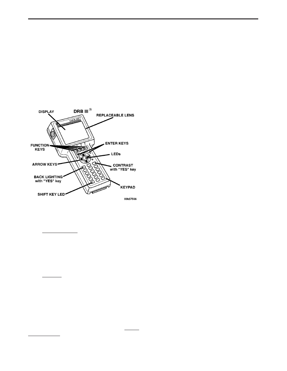
USING THE DRBIII
T
Refer to the DRBIII
t user’s guide for instructions
and assistance with reading diagnostic trouble
codes, erasing diagnostic trouble codes, and other
DRBIII
t functions.
3.4
DRBIII
T ERROR MESSAGES AND
BLANK SCREEN
If any of the following error messages appear on
the DRBIII
t screen, refer to the Vehicle Communi-
cations Manual for diagnosis and repair.
– cartridge error
– low battery
– ram result failure
– high battery
– keypad test failure
If the DRBIII
t has a blank screen, do the follow-
ing:
– Ensure there is a good body ground at the data
link connector
– Use the process of elimination. Sequentially
substitute
another
cable,
cartridge,
and
DRBIII
t until the condition is corrected
Under normal operation, the DRBIII
t will display
only two error messages:
– User-Requested
WARM
Boot
or
User-
Requested COLD Boot
If the DRBIII
t should display any other message,
record the entire display and call the STAR Center.
This is a sample of such an error message display:
ver: 2.14
date: 26 Jul93
file: key_itf.cc
date: Jul 26 1993
line: 548
err: 0x1
User-Requested COLD Boot
Press MORE to switch between this display
and the application screen.
Press F4 when done noting information.
6
GENERAL INFORMATION
3.4.1
DRBIII
T DOES NOT POWER UP
If the LED’s do not light or no sound is emitted at
start up, check for loose cable connections or a bad
cable. Check the vehicle battery voltage and
grounds to Data Link connector. A minimum of 11
volts is required to adequately power the DRBIII
t.
If all connections are proper, and the vehicle
battery is fully charged, an inoperative DRBIII
t
may be the result of faulty cable or vehicle wiring.
3.4.2
DISPLAY IS NOT VISIBLE
Low temperatures will affect the visibility of the
display. Adjust the contrast to compensate for this
condition.
4.0
DISCLAIMERS, SAFETY,
WARNINGS
4.1
DISCLAIMERS
All information, illustrations, and specifications
contained in this manual are based on the latest
information available at the time of publication.
The right is reserved to make changes at any time
without notice.
4.2
SAFETY
4.2.1
TECHNICIAN SAFETY INFORMATION
WARNING: ENGINES PRODUCE CARBON
MONOXIDE THAT IS ODORLESS, CAUSES
SLOWER REACTION TIME, AND CAN LEAD
TO SERIOUS INJURY. WHEN THE ENGINE IS
OPERATING, KEEP SERVICE AREAS WELL
VENTILATED OR ATTACH THE VEHICLE
EXHAUST SYSTEM TO THE SHOP EXHAUST
REMOVAL SYSTEM.
Set the parking brake and block the wheels before
testing or repairing the vehicle. It is especially
important to block the wheels on front-wheel drive
vehicles; the parking brake does not hold the drive
wheels.
When servicing a vehicle always wear eye protec-
tion and remove any metal jewelry such as rings,
watchbands or bracelets that might make an inad-
vertent electrical contact.
When diagnosing an antilock brake system prob-
lem, it is important to follow approved procedures
where applicable. These procedures can be found in
service manual procedures. Following these proce-
dures is very important to the safety of individuals
performing diagnostic tests.
4.2.2
VEHICLE PREPARATION FOR
TESTING
Make sure the vehicle being tested has a fully
charged battery. If is does not, false diagnostic codes
or error messages may occur.
4.2.3
SERVICING SUB-ASSEMBLIES
Some components of the antilock brake and ad-
justable pedals systems are intended to be serviced
in assembly only. Attempting to remove or repair
certain system sub-components may result in per-
sonal injury and/or improper system operation.
Only those components with approved repair and
installation procedures in the service manual
should be serviced.
4.2.4
DRBIII
T SAFETY INFORMATION
WARNING: EXCEEDING THE LIMITS OF THE
DRBIII
T
MULTIMETER IS DANGEROUS. IT
CAN
EXPOSE
YOU
TO
SERIOUS
OR
POSSIBLY
FATAL
INJURY.
CAREFULLY
READ AND UNDERSTAND THE CAUTIONS
AND THE SPECIFICATION LIMITS.
•
Follow the vehicle manufacturer’s service speci-
fications at all times
•
Do not use the DRBIII
t if it has been damaged
•
Do not use the test leads if the insulation is
damaged or if metal is exposed
•
To avoid electrical shock, do not touch the test
leads, tips or the circuit being tested
•
Choose the proper range and function for the
measurement. Do not try voltage or current mea-
surements that may exceed the rated capacity
•
Do not exceed the limits shown in the table below:
7
GENERAL INFORMATION

FUNCTION
INPUT LIMIT
Volts
0 - 500 peak volts AC
0 - 500 volts DC
Ohms (resistance)*
0 -1.12 megohms
Frequency Measured
Frequency Generated
0 - 10 kHz
Temperature
-58 - 1100°F
-50 - 600°C
* Ohms cannot be measured if voltage is present.
Ohms can be measured only in a non-powered
circuit.
•
Voltage between any terminal and ground must
not exceed 500v DC or 500v peak AC
•
Use caution when measuring voltage above 25v
DC or 25v AC
•
Use the low current shunt to measure circuits up
to 10A. Use the high current clamp to measure
circuits exceeding 10A
•
When testing for the presence of voltage or cur-
rent, make sure the meter is functioning cor-
rectly. Take a reading of a known voltage or
current before accepting a zero reading
•
When measuring current, connect the meter in
series with the load
•
Disconnect the live test lead before disconnecting
the common test lead
•
When using the meter function, keep the
DRBIII
t away from spark plug or coil wires to
avoid measuring error from outside interference
4.3
WARNINGS
4.3.1
VEHICLE DAMAGE WARNINGS
Before disconnecting any control module, make
sure the ignition is ‘‘off ’’. Failure to do so could
damage the module.
When testing voltage or continuity at any control
module, use the terminal side (not the wire end) of
the connector. Do not probe a wire through the
insulation; this will damage it and eventually cause
it to fail because of corrosion.
Be careful when performing electrical tests so as
to prevent accidental shorting of terminals. Such
mistakes can damage fuses or components. Also, a
second code could be set, making diagnosis of the
original problem more difficult.
4.3.2
ROAD TESTING A COMPLAINT
VEHICLE
Some complaints will require a test drive as part
of the repair verification procedure. The purpose of
the test drive is to try to duplicate the diagnostic
code or symptom condition.
WARNING:
BEFORE
ROAD
TESTING
A
VEHICLE,
BE
SURE
THAT
ALL
COMPONENTS
ARE
REASSEMBLED.
DURING THE TEST DRIVE, DO NOT TRY TO
READ
THE
DRBIII
T
SCREEN
WHILE
IN
MOTION. DO NOT HANG THE DRBIII
T
FROM
THE REAR VIEW MIRROR OR OPERATE IT
YOURSELF.
HAVE
AN
ASSISTANT
AVAILABLE TO OPERATE THE DRBIII
T
.
4.4
DIAGNOSIS
1. Your diagnostic test procedure must begin with a
thorough visual inspection of the system compo-
nents for damage and for disconnected connec-
tors. A visual inspection consists of physically
looking for the possible cause of a malfunction. A
careful and thorough visual inspection of compo-
nents may quickly identify the cause of a mal-
function and eliminate the need for diagnostic
testing.
PERFORM THE FOLLOWING VISUAL IN-
SPECTIONS BEFORE DOING ANY DIAGNOS-
TIC TESTING. If a malfunction is not resolved by
the visual inspection, proceed with diagnostic test-
ing according to the instructions in the manual.
See Section 8.0 (Component Locations) for pic-
tures identifying the location of system compo-
nents.
Brake Fluid
Level
Visually inspect for the proper fluid
level within the fluid reservoir.
Hydraulic
Control Unit
Visually inspect the hydraulic as-
semblies for leaks and for damaged
or disconnected connectors.
Fuses
Visually inspect that all fuses are
properly installed.
Wheel Speed
Sensor
Connectors
Visually inspect both front wheel
speed sensor connectors for dam-
age or disconnection. Inspect the
rear axle speed sensor connectors.
Brake Fluid
Lines
Visually inspect brake fluid lines for
any leaks or damage.
Wheel Speed
Sensors
Visually inspect all wheel speed
sensor(s) and tone wheel(s) for any
damage.
Controller An-
tilock Brake
(CAB)
Visually inspect the CAB for a se-
cure mounting and the CAB connec-
tor for damage or loose connection.
Base Brake
System
Visually inspect the condition of the
parking brake, rotors, drums, and
calipers.
8
GENERAL INFORMATION

Adjustable
Pedals Motor
Visually inspect connections and
mounting for damage and misalign-
ment.
Adjustable
Pedals
Visually inspect the mechanical
components of the adjustable pedals
system for damage and misalign-
ment.
Adjustable
Pedals Switch
Visually inspect the Adjustable Ped-
als Switch for damage and discon-
nection.
2. Connect the DRBIII
t to the Data Link Con-
nector (DLC).
3. With the DRBIII
t, read active and stored
trouble codes and record them. If you encounter a
‘‘NO RESPONSE’’ message on the DRBIII
t while
accessing diagnostic menu, perform DRBIII
t No
Response Message test. For other DRBIII
t related
communication problems, refer to the Vehicle Com-
munications test in the Body Diagnostic manual.
Using the DRBIII
t, either reset the module to erase
all stored trouble codes or use the erase command
after reading all diagnostic trouble codes.
4. Turn ignition off, then on. If the diagnostic
trouble code doesn’t come back, refer to the diag-
nostic trouble code description. If the DRBIII
t dis-
plays diagnostic trouble codes, proceed to the ap-
propriate diagnostic test(s). If no diagnostic trouble
codes are present at the time, perform the System
Verification Test. WARNING: BEFORE PER-
FORMING ANY ROAD TEST, VERIFY THAT
FULL BRAKING CAPABILITY IS PRESENT.
5.0
REQUIRED TOOLS AND
EQUIPMENT
DRBIII
t (diagnostic read-out box)
jumper wires
ohmmeter
voltmeter
test light
6.0
GLOSSARY OF TERMS
ABS
antilock brake system
AC
alternating current
APS
adjustable pedals system
CAB
controller antilock brake
DLC
data link connector
DRP
dynamic rear proportioning
DTC
diagnostic trouble code
EBA
electronic brake apportioning
EBC
electronic brake controller
EVBP
electronic variable brake proportion-
ing
4WD
four wheel drive
FCM
front control module
HCU
hydraulic control unit
IC
integrated circuit
IPM
integrated power module
LF
left front
NGC
next generation control
NVRAM
non-volatile random access memory
PCI
programmable communication inter-
face (vehicle communication bus)
PWM
pulse width modulation
R
rear
RAM
random access memory
RF
right front
ROM
read only memory
RWAL
rear wheel antilock
WSS
wheel speed sensor
9
GENERAL INFORMATION

NOTES
10

7.0
DIAGNOSTIC INFORMATION AND
PROCEDURES
11

Symptom:
APS RELAY CONTROL CIRCUIT HIGH
When Monitored and Set Condition:
APS RELAY CONTROL CIRCUIT HIGH
When Monitored:
Ignition on.
Set Condition:
When the Front Control Module detects a short to voltage on the
Adjustable Pedals Relay Control circuit.
POSSIBLE CAUSES
ADJUSTABLE PEDALS RELAY
FRONT CONTROL MODULE INTERNAL FAULT
INTERMITTENT DTC
ADJUSTABLE PEDAL CONTROL CIRCUIT SHORT TO VOLTAGE
TEST
ACTION
APPLICABILITY
1
With the DRBIII
t, record and erase DTC’s.
Turn the ignition on.
With the DRBIII
t, read DTC’s.
Does the DRBIII
t display APS RELAY CONTROL CIRCUIT DTC active?
All
Yes
→ Go To 2
No
→ Go To 4
2
Turn the ignition off.
Replace the Adjustable Pedals Relay with a known good relay.
Turn the ignition on.
With the DRBIII
t, read DTC’s.
Does the DRBIII
t display APS RELAY CONTROL CIRCUIT HIGH DTC active?
All
Yes
→ Go To 3
No
→ Replace the Adjustable Pedals Relay in accordance with the
Service Information.
Perform ADJUSTABLE PEDALS VERIFICATION TEST - VER
1.
12
ADJUSTABLE PEDALS

TEST
ACTION
APPLICABILITY
3
Turn the ignition off.
Remove the Front Control Module from the IPM.
Remove the Adjustable Pedals Relay.
Turn the ignition ON.
Measure the voltage between Adjustable Pedal Relay Control circuit and ground.
Is there any voltage present?
All
Yes
→ Repair the Adjustable Pedal Relay Control circuit for a short to
voltage.
Perform ADJUSTABLE PEDALS VERIFICATION TEST - VER
1.
No
→ Replace the Front Control Module in accordance with the Service
Information.
Perform ADJUSTABLE PEDALS VERIFICATION TEST - VER
1.
4
Turn the ignition off.
Visually inspect the related wiring harness. Look for any chafed, pierced, pinched, or
partially broken wires.
Visually inspect the related wire harness connectors. Look for broken, bent, pushed
out, or corroded terminals.
Refer to any Hotline letters or Technical Service Bulletins that may apply.
Were any problems found?
All
Yes
→ Repair as necessary.
Perform ADJUSTABLE PEDALS VERIFICATION TEST - VER
1.
No
→ Test Complete.
13
ADJUSTABLE PEDALS
APS RELAY CONTROL CIRCUIT HIGH —
Continued

Symptom:
APS RELAY CONTROL CIRCUIT LOW
When Monitored and Set Condition:
APS RELAY CONTROL CIRCUIT LOW
When Monitored:
Ignition on.
Set Condition:
When the Front Control Module detects a short to ground on the
Adjustable Pedals Relay Control circuit.
POSSIBLE CAUSES
ADJUSTABLE PEDALS RELAY
ADJUSTABLE PEDAL CONTROL CIRCUIT SHORT TO GROUND
FRONT CONTROL MODULE INTERNAL FAULT
INTERMITTENT DTC
TEST
ACTION
APPLICABILITY
1
With the DRBIII
t, record and erase DTC’s.
Turn the ignition on.
With the DRBIII
t, read DTC’s.
Does the DRBIII
t display APS RELAY CONTROL CIRCUIT DTC active?
All
Yes
→ Go To 2
No
→ Go To 4
2
Turn the ignition off.
Replace the Adjustable Pedals Relay with a known good relay.
Turn the ignition on.
With the DRBIII
t, read DTC’s.
Does the DRBIII
t display APS RELAY CONTROL CIRCUIT LOW DTC active?
All
Yes
→ Go To 3
No
→ Replace the Adjustable Pedals Relay in accordance with the
Service Information.
Perform ADJUSTABLE PEDALS VERIFICATION TEST - VER
1.
14
ADJUSTABLE PEDALS

TEST
ACTION
APPLICABILITY
3
Turn the ignition off.
Remove the Front Control Module from the IPM.
Remove the Adjustable Pedals Relay.
Measure the resistance between ground and the Adjustable Pedal Relay Control
circuit.
Is the resistance open?
All
Yes
→ Replace the Front Control Module in accordance with the Service
Information.
Perform ADJUSTABLE PEDALS VERIFICATION TEST - VER
1.
No
→ Repair the Adjustable Pedal Relay Control circuit for a short to
ground.
Perform ADJUSTABLE PEDALS VERIFICATION TEST - VER
1.
4
Turn the ignition off.
Visually inspect the related wiring harness. Look for any chafed, pierced, pinched, or
partially broken wires.
Visually inspect the related wire harness connectors. Look for broken, bent, pushed
out, or corroded terminals.
Refer to any Hotline letters or Technical Service Bulletins that may apply.
Were any problems found?
All
Yes
→ Repair as necessary.
Perform ADJUSTABLE PEDALS VERIFICATION TEST - VER
1.
No
→ Test Complete.
15
ADJUSTABLE PEDALS
APS RELAY CONTROL CIRCUIT LOW —
Continued

Symptom:
APS RELAY CONTROL CIRCUIT OPEN
When Monitored and Set Condition:
APS RELAY CONTROL CIRCUIT OPEN
When Monitored:
Ignition on.
Set Condition:
When the Front Control Module detects an open on the Adjustable Pedals
Relay Control circuit.
POSSIBLE CAUSES
ADJUSTABLE PEDALS RELAY
APS RELAY CONTROL CIRCUIT OPEN
FRONT CONTROL MODULE INTERNAL FAULT
INTERMITTENT DTC
TEST
ACTION
APPLICABILITY
1
With the DRBIII
t, record and erase DTC’s.
Turn the ignition on.
With the DRBIII
t, read DTC’s.
Does the DRBIII
t display APS RELAY CONTROL CIRCUIT DTC active?
All
Yes
→ Go To 2
No
→ Go To 4
2
Turn the ignition off.
Replace the Adjustable Pedals Relay with a known good relay.
Turn the ignition on.
With the DRBIII
t, read DTC’s.
Does the DRBIII
t display APS RELAY CONTROL CIRCUIT OPEN DTC active?
All
Yes
→ Go To 3
No
→ Replace the Adjustable Pedals Relay in accordance with the
Service Information.
Perform ADJUSTABLE PEDALS VERIFICATION TEST - VER
1.
3
Turn the ignition off.
Remove the Front Control Module from the IPM.
Remove the Adjustable Pedals Relay.
Measure the resistance of the Adjustable Pedal Relay Control circuit.
Is the resistance open?
All
Yes
→ Repair the Adjustable Pedal Relay Control circuit for an open.
Perform ADJUSTABLE PEDALS VERIFICATION TEST - VER
1.
No
→ Replace the Front Control Module in accordance with the Service
Information.
Perform ADJUSTABLE PEDALS VERIFICATION TEST - VER
1.
16
ADJUSTABLE PEDALS

TEST
ACTION
APPLICABILITY
4
Turn the ignition off.
Visually inspect the related wiring harness. Look for any chafed, pierced, pinched, or
partially broken wires.
Visually inspect the related wire harness connectors. Look for broken, bent, pushed
out, or corroded terminals.
Refer to any Hotline letters or Technical Service Bulletins that may apply.
Were any problems found?
All
Yes
→ Repair as necessary.
Perform ADJUSTABLE PEDALS VERIFICATION TEST - VER
1.
No
→ Test Complete.
17
ADJUSTABLE PEDALS
APS RELAY CONTROL CIRCUIT OPEN —
Continued
Symptom:
BODY STYLE MISMATCH - 85
When Monitored and Set Condition:
BODY STYLE MISMATCH - 85
When Monitored:
Ignition on.
Set Condition:
When both the traceability code number and body style can not be read
from the NVRAM or they are invalid.
POSSIBLE CAUSES
WRONG CAB OR CAB NOT PROGRAMMED FROM FACTORY
TEST
ACTION
APPLICABILITY
1
Turn the ignition on.
With the DRBIII
t, erase DTC’s.
Turn the ignition off.
Turn the ignition on.
With the DRBIII
t, read DTC’s.
Does the DRBIII
t display BODY STYLE MISMATCH?
All
Yes
→ Replace the Controller Antilock Brake in accordance with the
Service Information. Refer to the symptom *Replacing the Con-
troller Antilock Brake for additional information.
Perform ABS VERIFICATION TEST - VER 1.
No
→ Test Complete.
18
BRAKES (CAB)

Symptom:
BRAKE SWITCH CIRCUIT - 81
When Monitored and Set Condition:
BRAKE SWITCH CIRCUIT - 81
When Monitored:
Ignition on.
Set Condition:
Continuous brake applied signal after ignition turn-on and remaining
with sensed speed above 37.5 MPH (RWAL) or 15 MPH (ABS) for over 10 seconds and/or
ABS active for at least a second with brake switch released and never sensed brake applied
since power up.
POSSIBLE CAUSES
VERIFY THE CONCERN
CAB BRAKE STATUS
BRAKE SWITCH OPEN
BRAKE SWITCH SENSE CIRCUIT SHORT TO VOLTAGE
BRAKE SWITCH SENSE CIRCUIT OPEN
BRAKE SWITCH GROUND CIRCUIT OPEN
CAB -- INTERNAL CONCERN
TEST
ACTION
APPLICABILITY
1
NOTE: IF DRIVER
(RIDES( THE BRAKES, A BRAKE CIRCUIT DIAGNOS-
TIC CODE MAYBE SET.
Turn the ignition off.
Ensure all accessories are turned off and the battery is fully charged.
Turn the ignition on.
With the DRBIII
t, erase DTCs.
CAUTION: Ensure braking capability is available before road testing.
Road test the vehicle for at least 5 minutes over 40 MPH. Perform several antilock
braking stops.
Monitor the Input/Output status of the brake switch while driving.
With the DRBIII
t, read DTCs.
Does the original DTC recur and/or intermittent brake switch operation occur?
All
Yes
→ Go To 2
No
→ Brake Switch circuit is operating correctly at this time. Check for
operator error. Inspect for intermittent condition using the wiring
diagram/schematic as a guide, inspect the wiring and connectors
for damage.
Perform ABS VERIFICATION TEST - VER 1.
19
BRAKES (CAB)

TEST
ACTION
APPLICABILITY
2
Turn ignition on.
With the DRBIII
t in Inputs/Outputs, read the Brake Switch status.
Press and release the brake pedal.
Does the Brake Switch status match that of the Brake Switch?
All
Yes
→ Using the wiring diagram/schematic as a guide, inspect the
wiring and connectors for damage.
Perform ABS VERIFICATION TEST - VER 1.
No
→ Go To 3
3
Disconnect the Brake Lamp Switch harness connector.
With the DRBIII
t in Inputs/Outputs, read the Brake Switch state.
Connect and disconnect a jumper wire between the Brake Switch Ground and Sense
circuits.
Does the DRBIII
t display OPEN and CLOSED (jumper connected)?
All
Yes
→ Replace the Brake Lamp Switch in accordance with the Service
Information.
Perform ABS VERIFICATION TEST - VER 1.
No
→ Go To 4
4
Turn the ignition off.
Disconnect the CAB harness connector.
Disconnect the Brake Lamp Switch harness connector.
Measure the voltage of the Brake Switch Sense circuit.
Is there any voltage present?
All
Yes
→ Repair the Brake Switch Sense circuit for a short to voltage.
Perform ABS VERIFICATION TEST - VER 1.
No
→ Go To 5
5
Turn the ignition off.
Disconnect the CAB harness connector.
Disconnect the Brake Lamp Switch harness connector.
Measure the resistance of the Brake Switch Sense circuit between the CAB connector
and the Brake Lamp Switch connector.
Is the Brake Switch Sense circuit open?
All
Yes
→ Repair the Brake Switch Sense circuit for an open circuit.
Perform ABS VERIFICATION TEST - VER 1.
No
→ Go To 6
6
Turn the ignition off.
Disconnect the Brake Lamp Switch harness connector.
Measure the resistance of the Ground circuit.
Is the resistance below 5.0 ohms?
All
Yes
→ Replace the Controller Antilock Brake in accordance with the
Service Information. Refer to the symptom *Replacing the Con-
troller Antilock Brake for additional information.
Perform ABS VERIFICATION TEST - VER 1.
No
→ Repair the Brake Switch Ground circuit for an open circuit.
Perform ABS VERIFICATION TEST - VER 1.
20
BRAKES (CAB)
BRAKE SWITCH CIRCUIT - 81 —
Continued

Symptom:
ECU INTERNAL FAILURE - 75
When Monitored and Set Condition:
ECU INTERNAL FAILURE - 75
When Monitored:
Ignition ON.
Set Condition:
When the CAB internal microprocessor has an open/short in the status
line which fails to transmit at the correct frequency.
POSSIBLE CAUSES
WHEEL SPEED SENSOR FAILURE
CAB INTERNAL FAILURE
TEST
ACTION
APPLICABILITY
1
Turn the ignition on.
With the DRBIII
t, erase DTC’s.
Turn the ignition off.
Turn the ignition on.
NOTE: Ensure Wheel Speed Sensors are working properly.
With the DRBIII
t, read DTC’s.
Does the DRBIII
t display ECU INTERNAL FAILURE and WHEEL SPEED SEN-
SOR DTC’s?
All
Yes
→ Refer to the Table of Contents information in this manual for the
related Wheel Speed Sensor DTC’s.
Perform ABS VERIFICATION TEST - VER 1.
No
→ Replace the Controller Antilock Brake in accordance with the
Service Information. Refer to the symptom *Replacing the Con-
troller Antilock Brake for additional information.
Perform ABS VERIFICATION TEST - VER 1.
21
BRAKES (CAB)

Symptom:
EXCESSIVE DUMP TIME - 69
When Monitored and Set Condition:
EXCESSIVE DUMP TIME - 69
When Monitored:
Ignition on.
Set Condition:
Antilock mode is active. Wheel speed is below 4 MPH (RWAL) and above
4 MPH (ABS). Vehicle is in two wheel drive mode. Wheel speed history ruling out any
unusual events during the proceeding 15 seconds (RWAL) and 9 seconds (ABS). Need for
more than maximum allowable dump cycles.
POSSIBLE CAUSES
BRAKE SYSTEM MECHANICAL CONCERN
TONE WHEEL CONCERN
WHEEL BEARING FAULT
WHEEL SPEED WIRING HARNESS CONCERN
HCU INTERNAL CONCERN
LOADED WHEEL BEARING/SUSPENSION CONCERN
TEST
ACTION
APPLICABILITY
1
Inspect the front and rear brakes for anything that would cause the wheel(s) to lock
during braking.
Is there anything mechanically wrong with the Braking System?
All
Yes
→ Repair the mechanical braking system as necessary.
Perform ABS VERIFICATION TEST - VER 1.
No
→ Go To 2
2
Turn the ignition off.
Inspect the Tone Wheel for damaged, missing teeth or looseness.
Note: The Tone Wheel Teeth should be perfectly square, not bent or nicked.
Is the Tone Wheel OK?
All
Yes
→ Go To 3
No
→ Replace the Tone Wheel in accordance with the Service Informa-
tion.
Perform ABS VERIFICATION TEST - VER 1.
3
Turn the ignition off.
Inspect the wheel bearings for excessive run out or clearance.
Is the bearing clearance OK?
All
Yes
→ Go To 4
No
→ Repair as necessary.
Perform ABS VERIFICATION TEST - VER 1.
22
BRAKES (CAB)

TEST
ACTION
APPLICABILITY
4
Engine Running.
Raise and support the vehicle.
With the DRBIII
t in Sensors, read the Wheel Speed Sensor signals.
WARNING: BE SURE TO KEEP HANDS, FEET AND CLOTHING CLEAR OF
ROTATING COMPONENTS.
Allow the drive wheels to rotate.
Rotate the non-driven wheels by hand.
Wiggle Wheel Speed wiring harnesses.
With the DRBIII
t in Sensors, read the Wheel Speed Sensor outputs.
Is there a wheel speed dropout when a wiring harness is wiggled?
All
Yes
→ Repair the Wheel Speed wiring harness as necessary.
Perform ABS VERIFICATION TEST - VER 1.
No
→ Go To 5
5
CAUTION: Ensure vehicle has braking capability before road test.
Engine Running.
With the DRBIII
t in Sensors, read the Wheel Speed Sensor outputs.
NOTE: Have an assistant drive the vehicle, while monitoring the DRBIII
t.
Road test vehicle so wheel bearings and suspension are loaded.
With the DRBIII
t in Sensors, read the Wheel Speed Sensor outputs.
Is there a Wheel Speed Sensor dropout?
All
Yes
→ Repair as necessary.
Perform ABS VERIFICATION TEST - VER 1.
No
→ Replace the Hydraulic Control Unit in accordance with the
Service Information.
Perform ABS VERIFICATION TEST - VER 1.
23
BRAKES (CAB)
EXCESSIVE DUMP TIME - 69 —
Continued

Symptom:
FOUNDATION BRAKE - 78
When Monitored and Set Condition:
FOUNDATION BRAKE - 78
When Monitored:
Ignition on.
Set Condition:
Low feedback voltage from the Brake Fluid Level Switch Sense circuit.
POSSIBLE CAUSES
LOW BRAKE FLUID LEVEL
BRAKE FLUID LEVEL SWITCH SENSE CIRCUIT SHORT TO GROUND
BRAKE FLUID LEVEL SWITCH OPEN/SHORT
BRAKE FLUID LEVEL SWITCH GROUND CIRCUIT OPEN
CAB - INTERNAL CONCERN
FOUNDATION BRAKE INTERMITTENT DTC
TEST
ACTION
APPLICABILITY
1
Release the Parking Brake.
Turn the ignition off.
Turn the ignition on.
Watch the Instrument Cluster.
Does the Red Brake Warning Indicator come on and then stay on?
All
Yes
→ Go To 2
No
→ Go To 6
2
Turn the ignition off.
Inspect the Brake Fluid Level in the Master Cylinder Reservoir.
Is the Brake Fluid Level Low?
All
Yes
→ Repair as necessary.
Perform ABS VERIFICATION TEST - VER 1.
No
→ Go To 3
3
Turn the ignition off.
Disconnect the Brake Fluid Level Switch connector
Note: Check connector - Clean/repair as necessary.
Disconnect the CAB connector.
Note: Check connector - Clean/repair as necessary.
Measure the resistance between ground and the Brake Fluid Level Switch Sense
circuit.
Is the resistance below 5.0 ohms?
All
Yes
→ Repair the Brake Fluid Level Switch Sense circuit for a short to
ground.
Perform ABS VERIFICATION TEST - VER 1.
No
→ Go To 4
24
BRAKES (CAB)

TEST
ACTION
APPLICABILITY
4
Turn the ignition off.
Disconnect the Brake Fluid Level Switch connector.
Note: Check connector - Clean/repair as necessary.
NOTE: Ensure Master Cylinder float switch is not stuck in down position.
On the switch, measure the resistance between both of the Brake Fluid Level Switch
terminals.
NOTE: Resistance should be 10,000 ohms with a full Master Cylinder
Reservoir.
Is the resistance below 9,500 ohms or over 10,500 ohms?
All
Yes
→ Replace the Brake Fluid Level Switch in accordance with the
Service Information.
Perform ABS VERIFICATION TEST - VER 1.
No
→ Go To 5
5
Turn the ignition off.
Disconnect the Brake Fluid Level Switch connector.
Note: Check connector - Clean/repair as necessary.
Measure the resistance of the Brake Fluid level Switch Ground circuit.
Is the resistance below 5.0 ohms?
All
Yes
→ Replace the Controller Antilock Brake in accordance with the
Service Information. Refer to the symptom *Replacing the Con-
troller Antilock Brake for additional information.
Perform ABS VERIFICATION TEST - VER 1.
No
→ Repair the Brake Fluid Level Switch ground circuit for an open.
Perform ABS VERIFICATION TEST - VER 1.
6
Turn the ignition off.
Visually inspect the related wiring harness. Look for any chafed, pierced, pinched, or
partially broken wires.
Visually inspect the related wire harness connectors. Look for broken, bent, pushed
out, or corroded terminals.
Refer to any Hotline letters or Technical Service Bulletins that may apply.
Were any problems found?
All
Yes
→ Repair wiring harness/connectors as necessary.
Perform ABS VERIFICATION TEST - VER 1.
No
→ Test Complete.
25
BRAKES (CAB)
FOUNDATION BRAKE - 78 —
Continued

Symptom List:
INTERMITTENT SIGNAL FROM LEFT FRONT SENSOR - 27
INTERMITTENT SIGNAL FROM REAR SENSOR - 37
INTERMITTENT SIGNAL FROM RIGHT FRONT SENSOR - 23
LEFT FRONT SENSOR OPEN - 25
LEFT FRONT SENSOR SHORTED - 90
NO SIGNAL FROM LEFT FRONT SENSOR - 26
NO SIGNAL FROM REAR SENSOR - 36
NO SIGNAL FROM RIGHT FRONT SENSOR - 22
REAR SENSOR OPEN - 35
REAR SENSOR SHORTED - 93
RIGHT FRONT SENSOR OPEN - 21
RIGHT FRONT SENSOR SHORTED - 91
Test Note:
All symptoms listed above are diagnosed using the same tests.
The title for the tests will be INTERMITTENT SIGNAL FROM
LEFT FRONT SENSOR - 27.
When Monitored and Set Condition:
INTERMITTENT SIGNAL FROM LEFT FRONT SENSOR - 27
When Monitored:
Ignition turned on for at least 3.5 seconds. Average filtered speed for
the two front wheels above 6 km/h (4 mph). Speed for each suspect sensor above 32 km/h
(20 mph) (brake applied or ABS active) or 19 km/h (12 mph) (brake released or ABS
inactive).
Set Condition:
When there is a sudden change of output signal from the sensor.
INTERMITTENT SIGNAL FROM REAR SENSOR - 37
When Monitored:
Ignition turned on for at least 3.5 seconds. Average filtered speed for
the wheels above 19 km/h (12 mph) (brake released or ABS inactive) or 32 km/h (20 mph)
(brake applied or ABS active).
Set Condition:
When there is a sudden change of output signal from the sensor.
INTERMITTENT SIGNAL FROM RIGHT FRONT SENSOR - 23
When Monitored:
Ignition turned on for at least 3.5 seconds. Average filtered speed for
the two front wheels above 6 km/h (4 mph). Speed for each suspect sensor above 32 km/h
(20 mph) (brake applied or ABS active) or 19 km/h (12 mph) (brake released or ABS
inactive).
Set Condition:
When there is a sudden change of output signal from the sensor.
LEFT FRONT SENSOR OPEN - 25
When Monitored:
Ignition on.
Set Condition:
When the CAB detects an open wheel speed sensor circuit.
26
BRAKES (CAB)

LEFT FRONT SENSOR SHORTED - 90
When Monitored:
Ignition on.
Set Condition:
When no output signal and continuously excessive sensor resistance is
detected.
NO SIGNAL FROM LEFT FRONT SENSOR - 26
When Monitored:
Ignition on.
Set Condition:
When one sensors signal is prevented above 4 mph while one or more
other sensors are indicating that the vehicle is moving above 8 mph.
NO SIGNAL FROM REAR SENSOR - 36
When Monitored:
Ignition on.
Set Condition:
When one sensors signal is prevented above 4 mph while one or more
other sensors are indicating that the vehicle is moving above 8 mph.
NO SIGNAL FROM RIGHT FRONT SENSOR - 22
When Monitored:
Ignition on.
Set Condition:
When one sensors signal is prevented above 4 mph while one or more
other sensors are indicating that the vehicle is moving above 8 mph.
REAR SENSOR OPEN - 35
When Monitored:
Ignition on.
Set Condition:
When the CAB detects an open wheel speed sensor circuit.
REAR SENSOR SHORTED - 93
When Monitored:
Ignition on.
Set Condition:
When no output signal and continuously excessive sensor resistance is
detected.
RIGHT FRONT SENSOR OPEN - 21
When Monitored:
Ignition on.
Set Condition:
When the CAB detects an open wheel speed sensor circuit.
RIGHT FRONT SENSOR SHORTED - 91
When Monitored:
Ignition on.
Set Condition:
When no output signal and continuously excessive sensor resistance is
detected.
27
BRAKES (CAB)
INTERMITTENT SIGNAL FROM LEFT FRONT SENSOR - 27 —
Continued

POSSIBLE CAUSES
WHEEL SPEED SENSOR OR CONNECTOR DAMAGE, LOOSENESS OR METAL CHIPS
INTERMITTENT DTC - TOWING WITH IGNITION ON
WHEEL SPEED SENSOR (+) CIRCUIT SHORTED TO GROUND
WHEEL SPEED SENSOR (-) CIRCUIT SHORTED TO GROUND
WHEEL SPEED SENSOR SHORTED TO GROUND
CAB - INTERNAL SHORT OR OPEN
WHEEL SPEED SENSOR (+) CIRCUIT OPEN
WHEEL SPEED SENSOR (-) CIRCUIT OPEN
WHEEL SPEED SENSOR (+) CIRCUIT SHORTED TO VOLTAGE
WHEEL SPEED SENSOR (-) CIRCUIT SHORTED TO VOLTAGE
WHEEL SPEED SENSOR CIRCUITS SHORT TOGETHER
TONE WHEEL DAMAGED/MISSING
EXCESSIVE WHEEL SPEED SENSOR AIR GAP
WHEEL BEARING LOOSE/BINDING
WHEEL SPEED SENSOR RESISTANCE OUT OF SPECIFICATION
TEST
ACTION
APPLICABILITY
1
Turn the ignition on.
With the DRBIII
t, read DTC’s.
With the DRBIII
t, erase DTC’s.
Turn the ignition off.
Turn the ignition on.
With the DRBIII
t, read DTC’s.
Does the DRBIII
t display the appropriate Wheel Speed Sensor circuit failure DTC
right now?
All
Yes
→ Go To 2
No
→ Go To 15
2
Turn the ignition off.
Inspect the appropriate Wheel Speed Sensor for looseness.
Inspect the appropriate Wheel Speed Sensor harness connector.
Check connectors - Clean/repair as necessary.
Inspect the appropriate Wheel Speed Sensor for metal chips on sensor.
Is the Sensor or Connector damaged, loose, or metal chips on sensor present?
All
Yes
→ Repair as necessary.
Perform ABS VERIFICATION TEST - VER 1.
No
→ Go To 3
28
BRAKES (CAB)
INTERMITTENT SIGNAL FROM LEFT FRONT SENSOR - 27 —
Continued

TEST
ACTION
APPLICABILITY
3
Turn the ignition off.
Disconnect the appropriate CAB harness connector for the effected Wheel Speed
Sensor.
Note: Check connector - Clean/repair as necessary.
Measure the resistance across the appropriate Wheel Speed Sensor (+) and (-)
circuits at the CAB connector at 77°F.
Is the resistance 1800 - 2200(Front) OR 1600 - 2300(Rear) ohms?
All
Yes
→ Go To 4
No
→ Go To 7
4
Turn the ignition off.
Disconnect the appropriate Wheel Speed Sensor connector.
Disconnect the appropriate CAB harness connector for the effected Wheel Speed
Sensor.
Measure the resistance between the appropriate Wheel Speed Sensor (+) Circuit and
ground.
Is the resistance open?
All
Yes
→ Go To 5
No
→ Repair the appropriate Wheel Speed Sensor (+) Circuit Short to
Ground.
Perform ABS VERIFICATION TEST - VER 1.
5
Turn the ignition off.
Disconnect the appropriate Wheel Speed Sensor connector.
Note: Check connector - Clean/repair as necessary.
Disconnect the appropriate CAB harness connector for the effected Wheel Speed
Sensor.
Note: Check connector - Clean/repair as necessary.
Measure the resistance between the appropriate Wheel Speed Sensor (-) circuit and
ground.
Is the resistance open?
All
Yes
→ Go To 6
No
→ Repair the appropriate Wheel Speed Sensor (-) Circuit Short to
Ground.
Perform ABS VERIFICATION TEST - VER 1.
6
Turn the ignition off.
Disconnect the appropriate Wheel Speed Sensor connector.
Note: Check connector - Clean/repair as necessary.
On the component, measure the resistance between both of the appropriate Wheel
Speed Sensor terminals and ground.
Is the resistance open?
All
Yes
→ Replace the Controller Antilock Brake in accordance with the
Service Information. Refer to the symptom *Replacing the Con-
troller Antilock Brake for additional information.
Perform ABS VERIFICATION TEST - VER 1.
No
→ Replace the appropriate Wheel Speed Sensor in accordance with
the Service Information.
Perform ABS VERIFICATION TEST - VER 1.
29
BRAKES (CAB)
INTERMITTENT SIGNAL FROM LEFT FRONT SENSOR - 27 —
Continued

TEST
ACTION
APPLICABILITY
7
Turn the ignition off.
Disconnect the appropriate Wheel Speed Sensor connector.
Note: Check connector - Clean/repair as necessary.
Disconnect the appropriate CAB harness connector for the effected Wheel Speed
Sensor.
Note: Check connector - Clean/repair as necessary.
Measure the resistance of the appropriate Wheel Speed Sensor (+) circuit.
Is the resistance below 5 ohms?
All
Yes
→ Go To 8
No
→ Repair the appropriate Wheel Speed Sensor (+) Circuit Open.
Perform ABS VERIFICATION TEST - VER 1.
8
Turn the ignition off.
Disconnect the appropriate Wheel Speed Sensor connector.
Note: Check connector - Clean/repair as necessary.
Disconnect the appropriate CAB harness connector for the effected Wheel Speed
Sensor.
Note: Check connector - Clean/repair as necessary.
Measure the resistance of the appropriate Wheel Speed Sensor (-) circuit.
Is the resistance below 5 ohms?
All
Yes
→ Go To 9
No
→ Repair the appropriate Wheel Speed Sensor (-) Circuit Open.
Perform ABS VERIFICATION TEST - VER 1.
9
Turn the ignition off.
Disconnect the appropriate Wheel Speed Sensor harness connector.
Note: Check connector - Clean/repair as necessary.
Disconnect the appropriate CAB harness connector for the effected Wheel Speed
Sensor.
Note: Check connector - Clean/repair as necessary.
Turn the ignition on.
Measure the voltage of the appropriate Wheel Speed Sensor (+) Circuit.
Is there any voltage present?
All
Yes
→ Repair appropriate Wheel Speed Sensor (+) Circuit Shorted to
Voltage.
Perform ABS VERIFICATION TEST - VER 1.
No
→ Go To 10
10
Turn the ignition off.
Disconnect the appropriate Wheel Speed Sensor connector.
Note: Check connector - Clean/repair as necessary.
Disconnect the appropriate CAB harness connector for the effected Wheel Speed
Sensor.
Note: Check connector - Clean/repair as necessary.
Turn the ignition on.
Measure the voltage of the appropriate Wheel Speed Sensor (-) Circuit.
Is there any voltage present?
All
Yes
→ Repair the appropriate Wheel Speed Sensor (-) Circuit Short to
Voltage.
Perform ABS VERIFICATION TEST - VER 1.
No
→ Go To 11
30
BRAKES (CAB)
INTERMITTENT SIGNAL FROM LEFT FRONT SENSOR - 27 —
Continued

TEST
ACTION
APPLICABILITY
11
Turn the ignition off.
Disconnect the appropriate CAB harness connector for the effected Wheel Speed
Sensor.
Disconnect the appropriate Wheel Speed Sensor harness connector.
Measure the resistance through the appropriate Wheel Speed Sensor (+) and (-)
circuits at the CAB harness connector.
Is the resistance open?
All
Yes
→ Go To 12
No
→ Repair the appropriate Wheel Speed Sensor shorted together
circuits .
Perform ABS VERIFICATION TEST - VER 1.
12
Turn the ignition off.
Inspect for damaged or missing Tone Wheel.
NOTE: The Tone Wheel Teeth should be perfectly square, not bent or nicked.
Is the appropriate Tone Wheel ok?
All
Yes
→ Go To 13
No
→ Replace the appropriate Tone Wheel(s) in accordance with the
Service Information.
Perform ABS VERIFICATION TEST - VER 1.
13
Turn the ignition off.
Using a Feeler Gauge, measure the affected Wheel Speed Sensor Air Gap.
NOTE: Refer to the appropriate service information, if necessary, for
procedures or specifications.
Is the Air Gap OK?
All
Yes
→ Go To 14
No
→ Repair as necessary.
Perform ABS VERIFICATION TEST - VER 1.
14
Turn the ignition off.
Inspect the wheel bearings for excessive run out or clearance.
NOTE: Refer to the appropriate service information, as necessary, for
procedures or specifications.
Is the bearing clearance OK?
All
Yes
→ Replace the appropriate Wheel Speed Sensor in accordance with
the Service Information.
Perform ABS VERIFICATION TEST - VER 1.
No
→ Repair as necessary.
Perform ABS VERIFICATION TEST - VER 1.
15
Turn the ignition off.
NOTE: Ensure vehicle has not been towed with ignition ON
Visually inspect the related wiring harness. Look for any chafed, pierced, pinched, or
partially broken wires.
Visually inspect the related wire harness connectors. Look for broken, bent, pushed
out, or corroded terminals.
Refer to any Hotline letters or Technical Service Bulletins that may apply.
Were any problems found?
All
Yes
→ Repair as necessary.
Perform ABS VERIFICATION TEST - VER 1.
No
→ Test Complete.
31
BRAKES (CAB)
INTERMITTENT SIGNAL FROM LEFT FRONT SENSOR - 27 —
Continued

Symptom:
INTERNAL MAIN RELAY OPEN - 65
When Monitored and Set Condition:
INTERNAL MAIN RELAY OPEN - 65
When Monitored:
Ignition on.
Set Condition:
When all solenoid feedback voltages are low when they are expected to be
high(no solenoids energized).
POSSIBLE CAUSES
INTERMITTENT DTC
OPEN FUSED B(+) AND FUSED IGNITION SWITCH OUTPUT (RUN)
OPEN GROUND CIRCUITS
CAB - INTERNAL CONCERN
TEST
ACTION
APPLICABILITY
1
NOTE: Ensure the battery is fully charged.
Turn the ignition on.
With the DRBIII
t, erase DTC’s.
Turn the ignition off.
Turn the ignition on.
With the DRBIII
t, read DTC’s.
Is the INTERNAL MAIN RELAY OPEN DTC present?
All
Yes
→ Go To 2
No
→ Go To 4
2
NOTE: CHECK FOR OPEN FUSES.
Turn the ignition off.
Disconnect the CAB harness connector.
Check connectors - Clean/repair as necessary.
Turn the ignition on.
Measure the voltage of the Fused B(+) and Fused Ignition Switch Output (RUN)
circuits.
Is the voltage above 11 volts?
All
Yes
→ Go To 3
No
→ Repair the appropriate circuit(s) for an open.
Perform ABS VERIFICATION TEST - VER 1.
32
BRAKES (CAB)

TEST
ACTION
APPLICABILITY
3
Turn the ignition off.
Disconnect the CAB harness connector.
Check connectors - Clean/repair as necessary.
Measure the resistance of the Ground circuits in the CAB harness connector.
Is the resistance below 5.0 ohms?
All
Yes
→ Replace and program the CAB Module in accordance with the
Service Information.
Perform ABS VERIFICATION TEST - VER 1.
No
→ Repair the Ground circuit(s) for an open.
Perform ABS VERIFICATION TEST - VER 1.
4
Turn the ignition off.
Visually inspect the related wiring harness. Look for any chafed, pierced, pinched, or
partially broken wires.
Visually inspect the related wire harness connectors. Look for broken, bent, pushed
out, or corroded terminals.
Refer to any Hotline letters or Technical Service Bulletins that may apply.
Were any problems found?
All
Yes
→ Repair as necessary.
Perform ABS VERIFICATION TEST - VER 1.
No
→ Test Complete.
33
BRAKES (CAB)
INTERNAL MAIN RELAY OPEN - 65 —
Continued

Symptom:
INTERNAL MAIN RELAY SHORTED - 66
When Monitored and Set Condition:
INTERNAL MAIN RELAY SHORTED - 66
When Monitored:
Ignition on.
Set Condition:
When the relay feedback voltage is high when the power relay is supposed
to be open.
POSSIBLE CAUSES
INTERMITTENT DTC
OPEN FUSED B(+) AND FUSED IGNITION SWITCH OUTPUT (RUN)
OPEN GROUND CIRCUITS
CAB - INTERNAL CONCERN
TEST
ACTION
APPLICABILITY
1
NOTE: Ensure the battery is fully charged.
Turn the ignition on.
With the DRBIII
t, erase DTC’s.
Turn the ignition off.
Turn the ignition on.
With the DRBIII
t, read DTC’s.
Is the INTERNAL MAIN RELAY SHORTED DTC present?
All
Yes
→ Go To 2
No
→ Go To 4
2
NOTE: CHECK FOR OPEN FUSES.
Turn the ignition off.
Disconnect the CAB harness connector.
Check connectors - Clean/repair as necessary.
Turn the ignition on.
Measure the voltage of the Fused B(+) and Fused Ignition Switch Output (RUN)
circuits.
Is the voltage above 11 volts?
All
Yes
→ Go To 3
No
→ Repair the appropriate circuit(s) for an open.
Perform ABS VERIFICATION TEST - VER 1.
34
BRAKES (CAB)

TEST
ACTION
APPLICABILITY
3
Turn the ignition off.
Disconnect the CAB harness connector.
Check connectors - Clean/repair as necessary.
Measure the resistance of the Ground circuits in the CAB harness connector.
Is the resistance below 5.0 ohms?
All
Yes
→ Replace and program the CAB Module in accordance with the
Service Information.
Perform ABS VERIFICATION TEST - VER 1.
No
→ Repair the Ground circuit(s) for an open.
Perform ABS VERIFICATION TEST - VER 1.
4
Turn the ignition off.
Visually inspect the related wiring harness. Look for any chafed, pierced, pinched, or
partially broken wires.
Visually inspect the related wire harness connectors. Look for broken, bent, pushed
out, or corroded terminals.
Refer to any Hotline letters or Technical Service Bulletins that may apply.
Were any problems found?
All
Yes
→ Repair as necessary.
Perform ABS VERIFICATION TEST - VER 1.
No
→ Test Complete.
35
BRAKES (CAB)
INTERNAL MAIN RELAY SHORTED - 66 —
Continued

Symptom List:
LEFT FRONT DUMP SOLENOID OPEN - 46
LEFT FRONT DUMP SOLENOID SHORTED - 48
LEFT FRONT ISOLATION SOLENOID OPEN - 45
LEFT FRONT ISOLATION SOLENOID SHORTED - 47
REAR DUMP SOLENOID OPEN - 52
REAR DUMP SOLENOID SHORTED - 54
REAR ISOLATION SOLENOID OPEN - 51
REAR ISOLATION SOLENOID SHORTED - 53
RIGHT FRONT DUMP SOLENOID OPEN - 42
RIGHT FRONT DUMP SOLENOID SHORTED - 44
RIGHT FRONT ISOLATION SOLENOID OPEN - 41
RIGHT FRONT ISOLATION SOLENOID SHORTED - 43
Test Note:
All symptoms listed above are diagnosed using the same tests.
The title for the tests will be LEFT FRONT DUMP SOLENOID
OPEN - 46.
When Monitored and Set Condition:
LEFT FRONT DUMP SOLENOID OPEN - 46
When Monitored:
Ignition on.
Set Condition:
When there is low logic feedback voltage from the solenoid when it is
expected to be high (solenoid not energized).
LEFT FRONT DUMP SOLENOID SHORTED - 48
When Monitored:
Ignition on.
Set Condition:
When there is high logic feedback voltage from the solenoid when it is
supposed to be low (solenoid energized).
LEFT FRONT ISOLATION SOLENOID OPEN - 45
When Monitored:
Ignition on.
Set Condition:
When there is low logic feedback voltage from the solenoid when it is
expected to be high (solenoid not energized).
LEFT FRONT ISOLATION SOLENOID SHORTED - 47
When Monitored:
Ignition on.
Set Condition:
When there is high logic feedback voltage from the solenoid when it is
supposed to be low (solenoid energized).
36
BRAKES (CAB)

REAR DUMP SOLENOID OPEN - 52
When Monitored:
Ignition on.
Set Condition:
When there is low logic feedback voltage from the solenoid when it is
expected to be high (solenoid not energized).
REAR DUMP SOLENOID SHORTED - 54
When Monitored:
Ignition on.
Set Condition:
When there is high logic feedback voltage from the solenoid when it is
supposed to be low (solenoid energized).
REAR ISOLATION SOLENOID OPEN - 51
When Monitored:
Ignition on.
Set Condition:
When there is low logic feedback voltage from the solenoid when it is
expected to be high (solenoid not energized).
REAR ISOLATION SOLENOID SHORTED - 53
When Monitored:
Ignition on.
Set Condition:
When there is high logic feedback voltage from the solenoid when it is
supposed to be low (solenoid energized).
RIGHT FRONT DUMP SOLENOID OPEN - 42
When Monitored:
Ignition on.
Set Condition:
When there is low logic feedback voltage from the solenoid when it is
expected to be high (solenoid not energized).
RIGHT FRONT DUMP SOLENOID SHORTED - 44
When Monitored:
Ignition on.
Set Condition:
When there is high logic feedback voltage from the solenoid when it is
supposed to be low (solenoid energized).
RIGHT FRONT ISOLATION SOLENOID OPEN - 41
When Monitored:
Ignition on.
Set Condition:
When there is low logic feedback voltage from the solenoid when it is
expected to be high (solenoid not energized).
RIGHT FRONT ISOLATION SOLENOID SHORTED - 43
When Monitored:
Ignition on.
Set Condition:
When there is high logic feedback voltage from the solenoid when it is
supposed to be low (solenoid energized).
37
BRAKES (CAB)
LEFT FRONT DUMP SOLENOID OPEN - 46 —
Continued

POSSIBLE CAUSES
INTERMITTENT DTC
OPEN FUSED B(+) AND FUSED IGNITION SWITCH OUTPUT (RUN)
OPEN GROUND CIRCUITS
CAB - INTERNAL CONCERN
TEST
ACTION
APPLICABILITY
1
Turn the ignition on.
With the DRBIII
t, erase DTC’s.
Turn the ignition off.
Turn the ignition on.
With the DRBIII
t, read DTC’s.
Is there a OPEN SOLENOID or SHORTED SOLENOID DTC present?
All
Yes
→ Go To 2
No
→ Go To 4
2
NOTE: CHECK FOR OPEN FUSES.
Turn the ignition off.
Disconnect the CAB harness connector.
Check connectors - Clean/repair as necessary.
Turn the ignition on.
Measure the voltage of the Fused B(+) and Fused Ignition Switch Output (RUN)
circuits.
Is the voltage above 11 volts?
All
Yes
→ Go To 3
No
→ Repair the appropriate circuit(s) for an open.
Perform ABS VERIFICATION TEST - VER 1.
3
Turn the ignition off.
Disconnect the CAB harness connector.
Check connectors - Clean/repair as necessary.
Measure the resistance of the Ground circuits in the CAB harness connector.
Is the resistance below 5.0 ohms?
All
Yes
→ Replace and program the CAB Module in accordance with the
Service Information.
Perform ABS VERIFICATION TEST - VER 1.
No
→ Repair the Ground circuit(s) for an open.
Perform ABS VERIFICATION TEST - VER 1.
38
BRAKES (CAB)
LEFT FRONT DUMP SOLENOID OPEN - 46 —
Continued

TEST
ACTION
APPLICABILITY
4
Turn the ignition off.
Visually inspect the related wiring harness. Look for any chafed, pierced, pinched, or
partially broken wires.
Visually inspect the related wire harness connectors. Look for broken, bent, pushed
out, or corroded terminals.
Refer to any Hotline letters or Technical Service Bulletins that may apply.
Were any problems found?
All
Yes
→ Repair as necessary.
Perform ABS VERIFICATION TEST - VER 1.
No
→ Test Complete.
39
BRAKES (CAB)
LEFT FRONT DUMP SOLENOID OPEN - 46 —
Continued

Symptom:
MISMATCHED VIN - 84
When Monitored and Set Condition:
MISMATCHED VIN - 84
When Monitored:
Ignition on.
Set Condition:
Vehicle line or vehicle series information transmitted from PCM does not
match the expected values for ten seconds and/or vehicle line or series information not
transmitted by the PCM for ten seconds.
POSSIBLE CAUSES
INTERMITTENT DTC
WRONG VIN PROGRAMMED IN PCM/ WRONG PCM
INCORRECT CAB FOR VEHICLE
TEST
ACTION
APPLICABILITY
1
Turn the ignition on.
With the DRBIII
t, erase DTC’s.
Turn the ignition off.
Turn the ignition on.
Wait ten seconds.
Did the ABS Warning Indicator come on after ten seconds?
All
Yes
→ Go To 2
No
→ Go To 3
2
Turn the ignition on.
With the DRBIII
t, read the VIN status.
Compare programmed VIN with vehicle VIN.
Is the correct VIN programmed in the correct PCM for the vehicle line?
All
Yes
→ Replace the Controller Antilock Brake in accordance with the
Service Information. Refer to the symptom *Replacing the Con-
troller Antilock Brake for additional information.
Perform ABS VERIFICATION TEST - VER 1.
No
→ Program the correct VIN into the correct PCM for the vehicle line.
Perform ABS VERIFICATION TEST - VER 1.
3
Turn the ignition off.
Visually inspect the related wiring harness. Look for any chafed, pierced, pinched, or
partially broken wires.
Visually inspect the related wire harness connectors. Look for broken, bent, pushed
out, or corroded terminals.
Refer to any Hotline letters or Technical Service Bulletins that may apply.
Were any problems found?
All
Yes
→ Repair as necessary.
Perform ABS VERIFICATION TEST - VER 1.
No
→ Test Complete.
40
BRAKES (CAB)

Symptom:
NUMBER OF TONE RING TEETH OUT OF RANGE - 82
When Monitored and Set Condition:
NUMBER OF TONE RING TEETH OUT OF RANGE - 82
When Monitored:
Ignition on.
Set Condition:
When the teeth value is not in the range between 90 and 130.
POSSIBLE CAUSES
CAB - SETTING FALSE CODE
TONE RING/AXLE SIZE MISMATCH
TEST
ACTION
APPLICABILITY
1
Turn the ignition on.
With the DRBIII
t, read the axle size programmed into the CAB.
Inspect and identify the vehicle axle size.
Compare the axle size programmed into the CAB, and the actual axle size installed
into the vehicle.
Does the programmed axle size match the installed axle?
All
Yes
→ Replace the Controller Antilock Brake in accordance with the
Service Information. Refer to the symptom *Replacing the Con-
troller Antilock Brake for additional information.
Perform ABS VERIFICATION TEST - VER 1.
No
→ Using the DRBIIIt, reprogram the CAB for the correct axle.
Perform ABS VERIFICATION TEST - VER 1.
41
BRAKES (CAB)

Symptom List:
PUMP MOTOR CIRCUIT OPEN - 67
PUMP MOTOR STALLED - 68
Test Note:
All symptoms listed above are diagnosed using the same tests.
The title for the tests will be PUMP MOTOR CIRCUIT OPEN
- 67.
When Monitored and Set Condition:
PUMP MOTOR CIRCUIT OPEN - 67
When Monitored:
Ignition on.
Set Condition:
Ignition on for at least 3.5 seconds. ABS pump motor command never
given during the current ABS command. Low feedback voltage from the low side of the
motor.
PUMP MOTOR STALLED - 68
When Monitored:
Ignition on.
Set Condition:
When vehicle speed is above 15 mph without ABS active. Vehicle speed
above 4 mph with a fault from the previous ignition cycle. ABS pump motor command
given and then turned off. High feedback voltage from the low side of the motor
continuously.
POSSIBLE CAUSES
ABS PUMP MOTOR INTERMITTENT DTC
FUSED B(+) CIRCUIT INTERMITTENTLY SHORTED TO GROUND
FUSED B(+) CIRCUIT SHORTED TO GROUND
CAB - FUSED B(+) CIRCUIT SHORTED TO GROUND
FUSE OPEN - PUMP MOTOR CIRCUIT
NO B+ SUPPLY TO FUSE
ABS PUMP MOTOR INOPERATIVE
FUSED B(+) CIRCUIT OPEN
GROUND CIRCUIT OPEN
GROUND CIRCUIT HIGH RESISTANCE
CAB - INTERNAL FAULT
42
BRAKES (CAB)

TEST
ACTION
APPLICABILITY
1
Turn the ignition on.
With the DRBIII
t, read DTC’s.
With the DRBIII
t, erase DTC’s.
Turn the ignition off.
Turn the ignition on.
Turn the ignition off.
With the DRBIII
t, actuate the ABS pump motor.
Did the Pump Motor operate when actuated?
All
No
→ Go To 2
Yes
→ Go To 11
2
Turn the ignition off.
Remove and inspect the ABS Pump Motor fuse.
Is the Fuse open?
All
Yes
→ Go To 3
No
→ Go To 6
3
Turn the ignition off.
Make sure the Pump Motor connector is secure.
Visually inspect the Fused B(+) circuit in the wiring harness from the ABS PUMP
fuse to the CAB harness connector. Look for any sign of an intermittent short to
ground.
Is the wiring harness OK?
All
Yes
→ Go To 4
No
→ Repair the Fused B(+) circuit short to ground.
Perform ABS VERIFICATION TEST - VER 1.
4
Turn the ignition off.
Remove the ABS PUMP Fuse.
Disconnect the CAB harness connector.
Make sure the ABS Pump Motor connector is secure.
Note: Check connector - Clean/repair as necessary.
Measure the resistance of the Fused B(+) circuit to ground.
Is the resistance above 5.0 ohms?
All
Yes
→ Go To 5
No
→ Repair the Fused B(+) circuit short to ground.
Perform ABS VERIFICATION TEST - VER 1.
5
Turn the ignition off.
Make sure the Pump Motor connector is secure.
Remove the ABS PUMP Fuse.
NOTE: The CAB must be connected for the results of this test to be valid.
Measure the resistance between Fused (B)+ circuit and ground.
Is the resistance open?
All
Yes
→ Replace the ABS Pump Motor Fuse. If the fuse is open make sure
to check for a short to ground.
Perform ABS VERIFICATION TEST - VER 1.
No
→ Replace the Controller Antilock Brake in accordance with the
Service Information. Refer to the symptom *Replacing the Con-
troller Antilock Brake for additional information.
Perform ABS VERIFICATION TEST - VER 1.
43
BRAKES (CAB)
PUMP MOTOR CIRCUIT OPEN - 67 —
Continued

TEST
ACTION
APPLICABILITY
6
Turn the ignition off.
Remove the ABS PUMP Fuse.
Disconnect the CAB harness connector.
Note: Check connector - Clean/repair as necessary.
Measure the resistance of the Fused B (+) circuit between the ABS PUMP Fuse
Terminal and the CAB harness connector.
Is the resistance below 5 ohms?
All
Yes
→ Go To 7
No
→ Repair the Fused B(+) circuit for an open.
Perform ABS VERIFICATION TEST - VER 1.
7
Turn the ignition on.
Measure the voltage of the B(+) supply at the ABS PUMP Fuse terminal.
Is the voltage above 11 volts?
All
Yes
→ Go To 8
No
→ Repair the B+ supply for an open.
Perform ABS VERIFICATION TEST - VER 1.
8
Turn the ignition off.
Disconnect the ABS Pump Motor connector.
Connect a 10 gauge jumper wire between ABS Pump Motor Fused B (+) circuit and
a 40 Amp Fused B (+) circuit.
Connect a 10 gauge jumper wire between ABS Pump Motor ground circuit and
ground.
Monitor ABS Pump Motor operation.
Is the ABS Pump Motor operating?
All
Yes
→ Go To 9
No
→ Replace the ABS Pump Motor/Hydraulic Control Unit assembly.
Perform ABS VERIFICATION TEST - VER 1.
9
Turn the ignition off.
Disconnect the CAB harness connector.
Note: Check connector - Clean/repair as necessary.
Measure the resistance of the CAB Ground circuits.
Is the resistance below 5.0 ohms?
All
Yes
→ Go To 10
No
→ Repair the ground circuit for an open.
Perform ABS VERIFICATION TEST - VER 1.
10
Make sure the ABS Pump Motor connector is secure.
Turn the ignition on.
With the DRBIII
t, enable ABS Pump Motor actuation.
NOTE: ABS Pump Motor will not operate, but voltage will be applied.
Measure the voltage drop across the ABS Ground circuit connection, with ABS Pump
Motor actuation enabled.
Is the voltage below 0.1 volt?
All
Yes
→ Replace the Controller Antilock Brake in accordance with the
Service Information.
Perform ABS VERIFICATION TEST - VER 1.
No
→ Repair the Ground circuit for an open.
Perform ABS VERIFICATION TEST - VER 1.
44
BRAKES (CAB)
PUMP MOTOR CIRCUIT OPEN - 67 —
Continued

TEST
ACTION
APPLICABILITY
11
Turn the ignition off.
Visually inspect the related wiring harness. Look for any chafed, pierced, pinched, or
partially broken wires.
Make sure the Pump Motor connecter is secure.
Visually inspect the related wire harness connectors. Look for broken, bent, pushed
out, or corroded terminals.
Refer to any Hotline letters or Technical Service Bulletins that may apply.
Were any problems found?
All
Yes
→ Repair as necessary.
Perform ABS VERIFICATION TEST - VER 1.
No
→ Test Complete.
45
BRAKES (CAB)
PUMP MOTOR CIRCUIT OPEN - 67 —
Continued

Symptom:
RAM READ/WRITE - 71
When Monitored and Set Condition:
RAM READ/WRITE - 71
When Monitored:
Ignition on.
Set Condition:
Inability to set and subsequently recognize as being set, any bit in the
RAM and/or inability to clear, and subsequently recognize as being cleared, any bit in the
RAM.
POSSIBLE CAUSES
RAM READ/WRITE DTC CONDITION PRESENT
INTERMITTENT DTC
TEST
ACTION
APPLICABILITY
1
Turn the ignition on.
With the DRBIII
t, erase DTC’s.
Turn the ignition off.
Turn the ignition on.
With the DRBIII
t, read DTC’s.
Is the RAM READ/WRITE DTC present?
All
Yes
→ Replace the Controller Antilock Brake in accordance with the
Service Information. Refer to the symptom *Replacing the Con-
troller Antilock Brake for additional information.
Perform ABS VERIFICATION TEST - VER 1.
No
→ Go To 2
2
Turn the ignition off.
Visually inspect the related wiring harness. Look for any chafed, pierced, pinched, or
partially broken wires.
Visually inspect the related wire harness connectors. Look for broken, bent, pushed
out, or corroded terminals.
Refer to any Hotline letters or Technical Service Bulletins that may apply.
Were any problems found?
All
Yes
→ Repair as necessary.
Perform ABS VERIFICATION TEST - VER 1.
No
→ Test Complete.
46
BRAKES (CAB)

Symptom:
REAR RESET SWITCH CLOSED - 63
When Monitored and Set Condition:
REAR RESET SWITCH CLOSED - 63
When Monitored:
Ignition on.
Set Condition:
When not in antilock control mode and reset switch voltage is low.
POSSIBLE CAUSES
REAR RESET SWITCH CLOSED DTC CONDITION PRESENT
TEST
ACTION
APPLICABILITY
1
Turn the ignition on.
With the DRBIII
t, erase DTC’s.
Turn the ignition off.
Turn the ignition on.
With the DRBIII
t, read DTC’s.
Is the REAR RESET SWITCH CLOSED DTC present?
All
Yes
→ Replace the Hydraulic Control Unit in accordance with the
Service Information. Refer to the symptom *Replacing the Con-
troller Antilock Brake for additional information.
Perform ABS VERIFICATION TEST - VER 1.
No
→ Test Complete.
47
BRAKES (CAB)

Symptom:
ROM CHECKSUM - 72
When Monitored and Set Condition:
ROM CHECKSUM - 72
When Monitored:
Ignition on.
Set Condition:
Sum of all the storage bytes in the CAB’s ROM not equal to the original
sum stored in ROM.
POSSIBLE CAUSES
ROM CHECKSUM DTC CONDITION PRESENT
INTERMITTENT DTC
TEST
ACTION
APPLICABILITY
1
Turn the ignition on.
With the DRBIII
t, erase DTC’s.
Turn the ignition off.
Turn the ignition on.
With the DRBIII
t, read DTC’s.
Is the ROM CHECKSUM DTC set?
All
Yes
→ Replace the Controller Antilock Brake in accordance with the
Service Information. Refer to the symptom *Replacing the Con-
troller Antilock Brake for additional information.
Perform ABS VERIFICATION TEST - VER 1.
No
→ Go To 2
2
Turn the ignition off.
Visually inspect the related wiring harness. Look for any chafed, pierced, pinched, or
partially broken wires.
Visually inspect the related wire harness connectors. Look for broken, bent, pushed
out, or corroded terminals.
Refer to any Hotline letters or Technical Service Bulletins that may apply.
Were any problems found?
All
Yes
→ Repair as necessary.
Perform ABS VERIFICATION TEST - VER 1.
No
→ Test Complete.
48
BRAKES (CAB)

Symptom:
SYSTEM CONTROL MODE TIMEOUT - 74
When Monitored and Set Condition:
SYSTEM CONTROL MODE TIMEOUT - 74
When Monitored:
Ignition on.
Set Condition:
When vehicle is in antilock control mode. Vehicle speed is above 4 mph for
2 seconds. ABS mode is in continuous pressure control mode for an excessive period of time
(two minutes.)
POSSIBLE CAUSES
TONE WHEEL DAMAGE/MISSING
FOUNDATION BRAKE FAULTS
WHEEL BEARING LOOSE/BINDING
WHEEL SPEED SENSOR CONCERN
CAB - NO RESPONSE TO INPUT
BRAKE LAMP SWITCH
BRAKE SWITCH SENSE CIRCUIT
CAB - INTERNAL FAULT
TEST
ACTION
APPLICABILITY
1
Turn the ignition off.
Inspect the affected Tone Wheel(s) for damage, missing teeth, cracks, or looseness.
NOTE: The Tone Wheel teeth should be perfectly square, not bent, or nicked.
Is the affected Tone Wheel(s) OK?
All
Yes
→ Go To 2
No
→ Repair as necessary.
Perform ABS VERIFICATION TEST - VER 1.
2
Turn the ignition off.
Visually inspect brakes for locking up due to lining contamination or overheating.
Visually inspect all brake components for defects which may cause the brakes to
apply unequally.
Is any base brake component/hardware damaged?
All
Yes
→ Repair as necessary.
Perform ABS VERIFICATION TEST - VER 1.
No
→ Go To 3
49
BRAKES (CAB)

TEST
ACTION
APPLICABILITY
3
Turn the ignition off.
Inspect the wheel bearings for excessive run out or clearance.
NOTE: Refer to the appropriate service information, if necessary, for
procedures or specifications.
Is the wheel bearing clearance OK?
All
Yes
→ Go To 4
No
→ Repair as necessary.
Perform ABS VERIFICATION TEST - VER 1.
4
Turn the ignition on.
With the DRBIII
t, read DTCs.
With the DRBIII
t, erase DTCs.
Turn the ignition off.
Turn the ignition on.
With the DRBIII
t, read DTCs.
NOTE: Repair Wheel Speed Sensor concerns even if no active DTCs are
present before diagnosing.
Does the DRBIII
t display any Wheel Speed Sensor circuit failure DTC’s right now?
All
Yes
→ Repair as necessary.
Perform ABS VERIFICATION TEST - VER 1.
No
→ Go To 5
5
NOTE: IF THE DRIVER
(RIDES( THE BRAKES A (SYSTEM CONTROL
MODE TIMEOUT
( DTC MAYBE SET.
NOTE: DTC must be
(active(
With the DRBIII
t in Inputs/Outputs, read the Brake Switch state.
Apply and release the brake pedal.
Does the DRBIII
t follow the pedal position?
All
Yes
→ Using the wiring diagram/schematic as a guide, inspect the
wiring and connectors for damage. Inform driver that DTC can be
set by riding the brakes OR when they have had a very long
braking maneuver down a grade.
Perform ABS VERIFICATION TEST - VER 1.
No
→ Go To 6
6
Turn the ignition off.
Apply and release the brake pedal.
Observe the brake lamps.
Do the brake lamps operate OK?
All
Yes
→ Go To 7
No
→ Repair as necessary.
Perform ABS VERIFICATION TEST - VER 1.
50
BRAKES (CAB)
SYSTEM CONTROL MODE TIMEOUT - 74 —
Continued

TEST
ACTION
APPLICABILITY
7
NOTE: DTC must be
(active(
Turn the ignition off.
Disconnect the CAB connector.
Note: Check connector - Clean/repair as necessary.
Turn the ignition on.
Apply and release the brake pedal.
Check Brake Switch Sense for ground with pedal released and open with pedal
applied.
Does the Brake Switch Sense circuit change state as specified?
All
Yes
→ Replace the Controller Antilock Brake in accordance with the
Service Information. Refer to the symptom *Replacing the Con-
troller Antilock Brake for additional information.
Perform ABS VERIFICATION TEST - VER 1.
No
→ Repair the Brake Switch Sense circuit for a short to battery,
ground or for an open.
Perform ABS VERIFICATION TEST - VER 1.
51
BRAKES (CAB)
SYSTEM CONTROL MODE TIMEOUT - 74 —
Continued

Symptom:
SYSTEM OVER / UNDER VOLTAGE - 96
When Monitored and Set Condition:
SYSTEM OVER / UNDER VOLTAGE - 96
When Monitored:
Ignition on.
Set Condition:
When the CAB voltage drops below 9.5 volts or if the voltage rises above
17 volts. ABS will be disabled for the duration of the out of range voltage. If voltage rises
above 10 volts or drops below 16.5 volts, the code will reset if steady state of voltage is
present.
POSSIBLE CAUSES
CAB VOLTAGE CHECK
INTERMITTENT DTC
TEST
ACTION
APPLICABILITY
1
NOTE: Ensure the battery is fully charged.
Turn the ignition on.
With the DRBIII
t, record and erase DTC’s.
Turn the ignition off.
Start the engine.
Measure the voltage of the Fused B+ and Fused Ignition Switch Output (RUN)
circuits in the CAB connector.
Is the voltage between 10 volts and 16.5 volts and code is present?
All
Yes
→ Replace the Contoller Antilock Brake in accordance with the
Service Information. Refer to the symptom * Replacing the
Controller Antilock Brake for additional information.
Perform ABS VERIFICATION TEST - VER 1.
No
→ Go To 2
2
Turn the ignition off.
Using the wiring diagram/schematic as a guide, inspect the wiring and connectors.
Check connectors - Clean/repair as necessary.
Inspect the vehicle for aftermarket accessories that may exceed the Generator
System output.
Refer to any Hotline letters or Technical Service Bulletins that may apply.
Were any problems found?
All
Yes
→ Repair as necessary.
Perform ABS VERIFICATION TEST - VER 1.
No
→ Test Complete.
52
BRAKES (CAB)

Symptom:
TIRE REVS PER MILE OUT OF RANGE - 83
When Monitored and Set Condition:
TIRE REVS PER MILE OUT OF RANGE - 83
When Monitored:
Ignition on.
Set Condition:
Tire revolutions per mile not in the range between 400 and 900.
POSSIBLE CAUSES
INCORRECT TIRES PROGRAMMED INTO CAB
INTERMITTENT DTC
CAB INTERNAL FAULT
TEST
ACTION
APPLICABILITY
1
Turn the ignition on.
Observe the ABS Warning Indicator.
Is the ABS Warning Indicator Flashing?
All
Yes
→ Go To 2
No
→ Go To 3
2
Inspect all four of the tire sizes on the vehicle.
NOTE: Non-production size tire cannot be programmed into the CAB. The
production Powertrain, with the production size tires is the only emissions
certified configuration that is available for reprogramming.
Turn the ignition on.
With the DRBIII
t, read the tire size that is programmed into the CAB.
Does the DRBIII
t displayed tire size match the actual tire size on the vehicle?
All
Yes
→ Replace the Controller Antilock Brake in accordance with the
Service Information. Refer to the symptom *Replacing the Con-
troller Antilock Brake for additional information.
Perform ABS VERIFICATION TEST - VER 1.
No
→ Reprogram the tire size. Make sure that the ignition is on
throughout the entire reprogramming procedure.
Perform ABS VERIFICATION TEST - VER 1.
3
Turn the ignition off.
Visually inspect the related wiring harness. Look for any chafed, pierced, pinched, or
partially broken wires.
Visually inspect the related wire harness connectors. Look for broken, bent, pushed
out, or corroded terminals.
Refer to any Hotline letters or Technical Service Bulletins that may apply.
Were any problems found?
All
Yes
→ Repair as necessary.
Perform ABS VERIFICATION TEST - VER 1.
No
→ Test Complete.
53
BRAKES (CAB)

Symptom:
WATCHDOG - 73
When Monitored and Set Condition:
WATCHDOG - 73
When Monitored:
Ignition on.
Set Condition:
When there is a deviation from the expected result of a CAB internal self
check.
POSSIBLE CAUSES
INTERMITTENT DTC
OPEN FUSED B(+) AND FUSED IGNITION SWITCH OUTPUT (RUN)
OPEN GROUND CIRCUITS
CAB - INTERNAL CONCERN
TEST
ACTION
APPLICABILITY
1
Turn the ignition on.
With the DRBIII
t, erase DTC’s.
Turn the ignition off.
Turn the ignition on.
With the DRBIII
t, read DTC’s.
Is the WATCHDOG DTC present?
All
Yes
→ Go To 2
No
→ Go To 4
2
NOTE: CHECK FOR OPEN FUSES.
Turn the ignition off.
Disconnect the CAB harness connector.
Check connectors - Clean/repair as necessary.
Turn the ignition on.
Measure the voltage of the Fused B(+) and Fused Ignition Switch Output (RUN)
circuits in the CAB harness connector.
Is the voltage above 11 volts?
All
Yes
→ Go To 3
No
→ Repair the appropriate circuit(s) for an open.
Perform ABS VERIFICATION TEST - VER 1.
54
BRAKES (CAB)

TEST
ACTION
APPLICABILITY
3
Turn the ignition off.
Disconnect the CAB harness connector.
Check connectors - Clean/repair as necessary.
Measure the resistance of the Ground circuit(s) in the CAB harness connector.
Is the resistance below 5.0 ohms?
All
Yes
→ Replace and program the CAB Module in accordance with the
Service Information.
Perform ABS VERIFICATION TEST - VER 1.
No
→ Repair the Ground circuit(s) for an open.
Perform ABS VERIFICATION TEST - VER 1.
4
Turn the ignition off.
Visually inspect the related wiring harness. Look for any chafed, pierced, pinched, or
partially broken wires.
Visually inspect the related wire harness connectors. Look for broken, bent, pushed
out, or corroded terminals.
Refer to any Hotline letters or Technical Service Bulletins that may apply.
Were any problems found?
All
Yes
→ Repair as necessary.
Perform ABS VERIFICATION TEST - VER 1.
No
→ Test Complete.
55
BRAKES (CAB)
WATCHDOG - 73 —
Continued

Symptom:
WHEEL SPEED MISMATCH - 38
When Monitored and Set Condition:
WHEEL SPEED MISMATCH - 38
When Monitored:
Ignition on.
Set Condition:
When rotational wheel speed differing from the average wheel speed for
the vehicle by more than 13%. Average wheel speeds less than 40 MPH and greater than
10 MPH (no more than 1/2 MPH difference in the front wheel speeds). Average wheel
speeds less than 40 MPH and greater than 25 MPH (front wheel speed variance greater
than 1/2 MPH). No wheel slippage detected, not in antilock mode, system not disabled, and
no open sensor code.
POSSIBLE CAUSES
WHEEL SPEED MISMATCH DTC CONDITION PRESENT
INCORRECT TONE WHEEL
CAB INTERNAL FAULT
TEST
ACTION
APPLICABILITY
1
Turn the ignition off.
Inspect all four tire sizes and measure tire circumferences on vehicle.
Are any of the tires/wheels/tire circumferences significantly different in size?
All
Yes
→ Correct as necessary. All of the tires and wheels must be of
uniform size and circumference..
Perform ABS VERIFICATION TEST - VER 1.
No
→ Go To 2
2
Turn the ignition off.
Count number of teeth on the suspect Tone Wheel.
Does the suspect Tone Wheel match the non-suspect Tone Wheels?
All
Yes
→ Replace the Controller Antilock Brake in accordance with the
Service Information. Refer to the symptom *Replacing the Con-
troller Antilock Brake for additional information.
Perform ABS VERIFICATION TEST - VER 1.
No
→ Replace the Tone Wheel in accordance with the Service Informa-
tion.
Perform ABS VERIFICATION TEST - VER 1.
56
BRAKES (CAB)

Symptom:
*REPLACING THE CONTROLLER ANTILOCK BRAKE
POSSIBLE CAUSES
REPLACING THE CAB
ABS VERIFICATION TEST
TEST
ACTION
APPLICABILITY
1
Note: You must call STAR to recieve a new CAB.
Note: Failure to properly program the replacement CAB will result in a
blinking ABS indicator.
Turn the ignition off.
Replace the CAB.
With the DRBIII
t, check the Tire Size and Rear Axle Type.
If the DRBIII
t display’s the Tire size and Axle ratio, use the DRBIIIt select: MISC
then MODULE REPLACEMENT.
If the DRBIII
t does not display Tire Size and Rear Axle Type, use the DRBIIIt select:
MISC then SET PINION FACTOR.
Inspect rear tires to determine tire sizes.
Note: If the vehicle does not have production size tires listed on the DRBIII
t
menu screen, install Production Size tires on the vehicle.
Determine which rear axle type, not the axle ratio, is used on this vehicle.
NOTE: To identify the proper axle on the vehicle, refer to Component
Location in Chassis Diagnostic Procedures or Service Information on
MDS2.
Ignition on, engine not running.
With the DRBIII
t, program the correct tire size and rear axle type.
Road test the vehicle above 40 mph for at least two minutes. Check for any DTC’s.
Did any DTC’s set during the road test?
All
Yes
→ Refer to the Symptom List for further diagnostic tests.
Perform ABS VERIFICATION TEST - VER 1.
No
→ Go To 2
57
BRAKES (CAB)

TEST
ACTION
APPLICABILITY
2
Turn the ignition off.
Connect all previously disconnected components and connectors.
Ensure all accessories are turned off and the battery is fully charged.
Ensure that the Ignition is on, and with the DRBIII, erase all Diagnostic Trouble
Codes from ALL modules. Start the engine and allow it to run for 2 minutes and fully
operate the system that was malfunctioning.
Turn the ignition off and wait 5 seconds. Turn the ignition on and using the DRBIII,
read DTC’s from ALL modules.
If any Diagnostic Trouble Codes are present, return to Symptom list and troubleshoot
new or recurring symptom.
If there are no DTC’s present after turning ignition on, road test the vehicle for at
least 5 minutes. Perform several antilock braking stops.
Caution: Ensure braking capability is available before road testing.
Again, with the DRBIII
t read DTC’s. If any DTC’s are present, return to Symptom
list.
If there are no Diagnostic Trouble Codes (DTC’s) present, and the customer’s concern
can no longer be duplicated, the repair is complete.
Are any DTC’s present or is the original concern still present?
All
Yes
→ Refer to symptom list for problems related to active DTCs.
Perform ABS VERIFICATION TEST - VER 1.
No
→ Test Complete.
58
BRAKES (CAB)
*REPLACING THE CONTROLLER ANTILOCK BRAKE —
Continued

Symptom:
*VEHICLE SPEED SIGNAL OUTPUT
POSSIBLE CAUSES
CONTROLLER ANTILOCK BRAKE DTC’S PRESENT
INTERMITTENT VEHICLE SPEED SIGNAL
VEHICLE SPEED SIGNAL CIRCUIT SHORTED OR OPEN
CAB- NO SPEED SIGNAL OUTPUT
PCM - CAN’T READ VEHICLE SPEED SIGNAL
TEST
ACTION
APPLICABILITY
1
Turn the ignition on.
With the DRBIII
t, read DTC’s.
Is the Good Trip Counter for P-0500 displayed and Equal to 0?
All
Yes
→ Go To 2
No
→ Go To 5
2
Turn the ignition on.
With the DRBIII
t, read DTCs.
Check for Controller Antilock Brake DTC’s.
Are any CAB DTC’s present?
All
Yes
→ Repair all Controller Antilock Brake DTC’s before proceeding.
Perform ABS VERIFICATION TEST - VER 1.
No
→ Go To 3
3
Turn the ignition off.
Disconnect the Powertrain Control Module harness connectors.
Disconnect the CAB connector.
Ignition on, engine not running.
Check the Vehicle Speed Signal circuit for a short to B+, short to ground and for an
open.
Is the Vehicle Speed Signal circuit OK?
All
Yes
→ Go To 4
No
→ Repair the open Vehicle Speed Signal circuit for a short or an
open.
Perform ABS VERIFICATION TEST - VER 1.
59
BRAKES (CAB)

TEST
ACTION
APPLICABILITY
4
Turn ignition off.
Disconnect the CAB connector.
Connect a jumper wire to the Vehicle Speed Signal circuit in the CAB harness
connector.
Turn ignition on.
Quickly and repeatedly tap the jumper wire to ground.
With the DRBIII
t read the Vehicle Speed Signal display.
Is the DRBIII
t reading Vehicle Speed above 0 MPH?
All
Yes
→ Replace the Controller Antilock Brake in accordance with the
Service Information. Refer to the symptom *Replacing the Con-
troller Antilock Brake for additional information..
Perform ABS VERIFICATION TEST - VER 1.
No
→ Replace the Powertrain Control Module in accordance with the
Service Information.
Perform POWERTRAIN VERIFICATION TEST VER - 5.
5
At this time, the conditions required to set the DTC are not present.
NOTE: Use the Freeze Frame Data to help duplicate the conditions that set
the DTC. Pay particular attention to the DTC set conditions, such as, VSS,
MAP, ECT, and Load.
Note: Visually inspect the related wiring harness. Look for any chafed,
pierced, pinched, or partially broken wires.
Note: Visually inspect the related wire harness connectors. Look for broken,
bent, pushed out, or corroded terminals.
Note: Refer to any technical service bulletins that may apply.
Were any problems found?
All
Yes
→ Repair as necessary.
Perform ABS VERIFICATION TEST - VER 1.
No
→ Test Complete.
60
BRAKES (CAB)
*VEHICLE SPEED SIGNAL OUTPUT —
Continued

Symptom:
*NO RESPONSE FROM CONTROLLER ANTILOCK BRAKE
POSSIBLE CAUSES
NO RESPONSE FROM CAB
GROUND CIRCUIT OPEN
OPEN FUSED IGNITION SWITCH OUTPUT CIRCUIT
OPEN PCI BUS CIRCUIT
CONTROLLER ANTILOCK BRAKE
TEST
ACTION
APPLICABILITY
1
Turn the ignition on.
Note: As soon as one or more module communicates with the DRB, answer
the question.
With the DRB, attempt to communicate with the Airbag Control Module (ACM).
With the DRB, attempt to communicate with the Instrument Cluster.
Was the DRB able to I/D or establish communications with either of the modules?
All
Yes
→ Go To 2
No
→ Refer to the Communications category and perform the symptom
PCI Bus Communication Failure.
Perform ABS VERIFICATION TEST - VER 1.
2
Turn the ignition off.
Disconnect the CAB C1 harness connector.
Using a 12-volt test light connected to 12-volts, probe both ground circuits.
Is the test light illuminated for both circuits?
All
Yes
→ Go To 3
No
→ Repair the ground circuit(s) for an open.
Perform ABS VERIFICATION TEST - VER 1.
3
Turn the ignition off.
Disconnect the CAB C1 harness connector.
Turn the ignition on.
Using a 12-volt test light connected to ground, probe the Fused Ignition Switch
Output circuit.
Is the test light illuminated?
All
Yes
→ Go To 4
No
→ Check IPM fuse #35 for an open. If OK, repair the Fused Ignition
Switch Output circuit for an open.
Perform ABS VERIFICATION TEST - VER 1.
61
COMMUNICATION

TEST
ACTION
APPLICABILITY
4
Note: Ensure there is PCI Bus communication with other modules on the
vehicle before proceeding. If not, refer to the symptom list from the menu
and repair as necessary.
Disconnect the CAB C1 harness connector.
Use Scope input cable CH7058, Cable to Probe adapter CH7062, and the red and
black test probes.
Connect the scope input cable to the channel one connector on the DRB. Attach the
red and black leads and the cable to probe adapter to the scope input cable.
With the DRBIII
t select Pep Module Tools.
Select lab scope.
Select Live Data.
Select 12 volt square wave.
Press F2 for Scope.
Press F2 and use the down arrow to set voltage range to 20 volts. Set Probe to x10.
Press F2 again when complete.
Connect the Black lead to the chassis ground. Connect the Red lead to the PCI Bus
circuit in the CAB connector.
Turn the ignition on.
Observe the voltage display on the DRB Lab Scope.
Does the voltage pulse from 0 to approximately 7.5 volts?
All
Yes
→ Go To 5
No
→ Repair the PCI Bus circuit for an open.
Perform ABS VERIFICATION TEST - VER 1.
5
If there are no possible causes remaining, view repair.
All
Repair
Replace the Controller Antilock Brake in accordance with the
Service Information.
Perform ABS VERIFICATION TEST - VER 1.
62
COMMUNICATION
*NO RESPONSE FROM CONTROLLER ANTILOCK BRAKE —
Continued

Verification Tests
ABS VERIFICATION TEST - VER 1
APPLICABILITY
1. Turn the ignition off.
2. Connect all previously disconnected components and connectors.
3. Ensure all accessories are turned off and the battery is fully charged.
4. Ensure that the Ignition is on, and with the DRBIII
t, erase all Diagnostic Trouble Codes
from ALL modules. Start the engine and allow it to run for 2 minutes and fully operate the
system that was malfunctioning.
5. Turn the ignition off and wait 5 seconds. Turn the ignition on and using the DRBIII, read
DTC’s from ALL modules.
6. If any Diagnostic Trouble Codes are present, return to Symptom list and troubleshoot new
or recurring symptom.
7. If there are no DTC’s present after turning ignition on, road test the vehicle for at least 5
minutes. Perform several antilock braking stops.
8. Caution: Ensure braking capability is available before road testing.
9. Again, with the DRBIII
t read DTC’s. If any DTC’s are present, return to Symptom list.
10. If there are no Diagnostic Trouble Codes (DTC’s) present, and the customer’s concern can
no longer be duplicated, the repair is complete.
Are any DTC’s present or is the original concern still present?
All
Yes
→ Repair is not complete, refer to appropriate symptom.
No
→ Repair is complete.
ADJUSTABLE PEDALS VERIFICATION TEST - VER 1
APPLICABILITY
1. Activate the Adjustable Pedals through the full range of movement.
2. Verify that the Adjustable Pedals system is disabled with the vehicle in Reverse.
3. Road test the vehicle to verify that the Adjustable Pedals system is disabled with Speed
Control activated.
4. With the DRBIII
t, erase DTCs.
5. With the DRBIII
t, read DTCs.
Are any DTC’s present or is the original complaint still present?
All
Yes
→ Repair is not complete, refer to appropriate symptom.
No
→ Repair is complete.
63
VERIFICATION TESTS

POWERTRAIN VERIFICATION TEST VER - 5
APPLICABILITY
1. Inspect the vehicle to ensure that all engine components are properly installed and
connected. Reassemble and reconnect components as necessary.
2. If any existing diagnostic trouble codes have not been repaired, go to the appropriate
Symptom List and follow path specified.
3. Connect the DRBIII
t to the data link connector.
4. Ensure the fuel tank has at least a quarter tank of fuel. Turn off all accessories.
5. If the PCM was not replaced skip steps 6 through 8 and continue the verification.
6. If the PCM was replaced, the correct VIN and mileage must be programmed or a DTC will
set in the ABS and Air Bag modules. In addition, if the vehicle is equipped with Sentry Key
Immobilizer Module (SKIM), Secret Key data must be updated to enable start.
7. For ABS and Air Bag systems: Enter correct VIN and Mileage in PCM. Erase codes in ABS
and Air Bag modules.
8. For SKIM theft alarm: Connect DRBIII
t to data link connectorto Theft Alarm, SKIM, Misc.
and place SKIM in secured access mode by using the appropriate PIN code for this vehicle.
Select Update the Secret Key data. Data will be transferred from SKIM to PCM.
9. If the Catalyst was replaced, with the DRBIII
t go to the miscellaneous Menu Option
9Catalyst Replaced9 and press enter.
10. If a Comprehensive Component DTC was repaired, perform steps 10-13. If a Major OBDII
Monitor DTC was repaired skip those steps and continue verification.
11. After the ignition has been off for at least 10 seconds, restart the vehicle and run 2 minutes.
12. With the DRBIII
t, monitor the appropriate pre-test enabling conditions until all conditions
have been met. Once the conditions have been met, switch screen to the appropriate OBDII
monitor, (Audible beeps when the monitor is running).
13. If the conditions cannot be duplicated, erase all DTC with the DRBIII
t.
Did the OBD II Monitor run successfully and has the Good Trip Counter changed to one or
more?
All
Yes
→ Repair is complete.
No
→ Check for any related Technical Service Bulletins and/or refer to the
appropriate Symptoms list (Diagnostic Procedure).
64
VERIFICATION TESTS
Verification Tests —
Continued
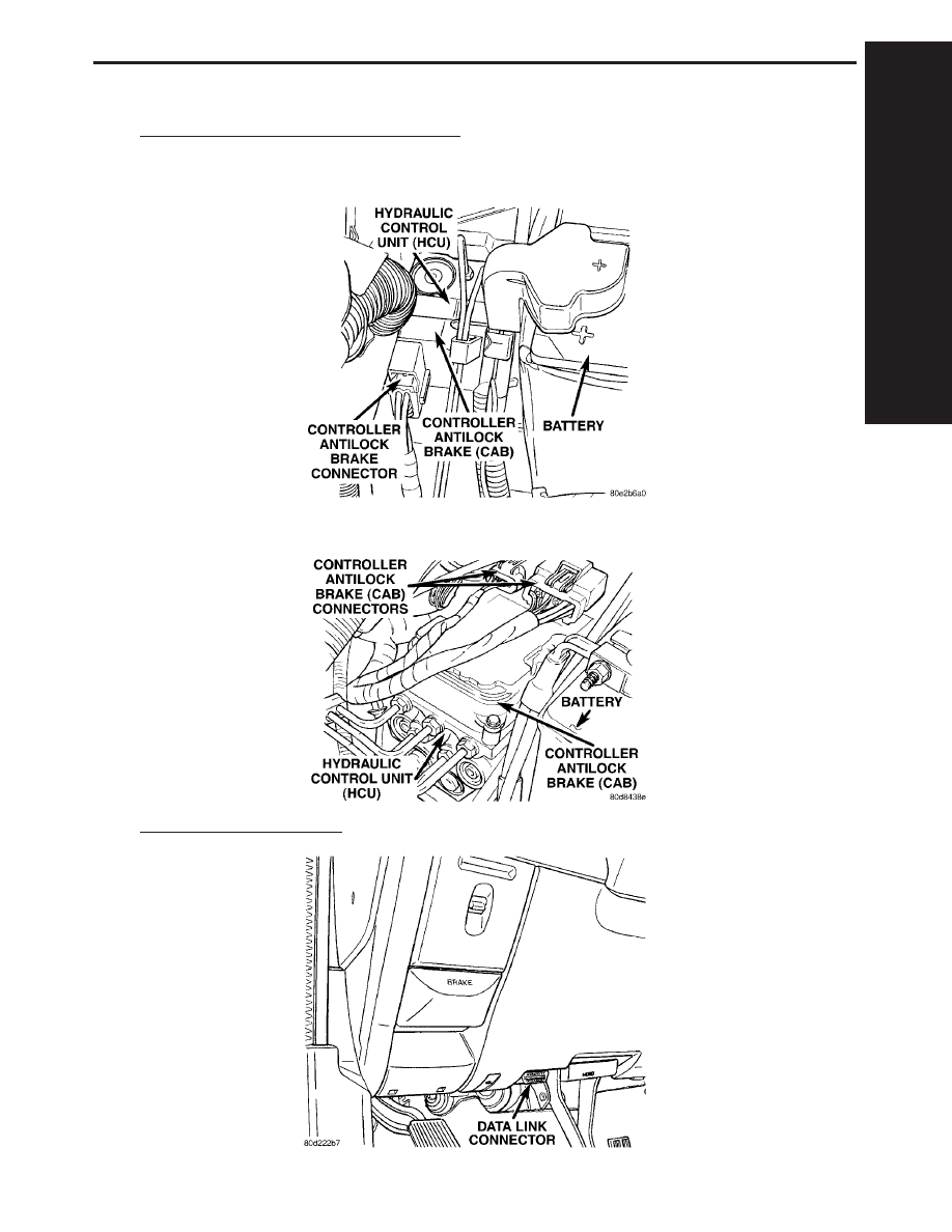
8.0
COMPONENT LOCATIONS
8.1
CONTROLLER ANTILOCK BRAKE (CAB)
8.1.1
EBC 125 (RWAL)
8.1.2
EBC 325 (ABS)
8.2
DATA LINK CONNECTOR
C
O
M
P
O
N
E
N
T
L
O
C
A
T
I
O
N
S
65
COMPONENT LOCATIONS
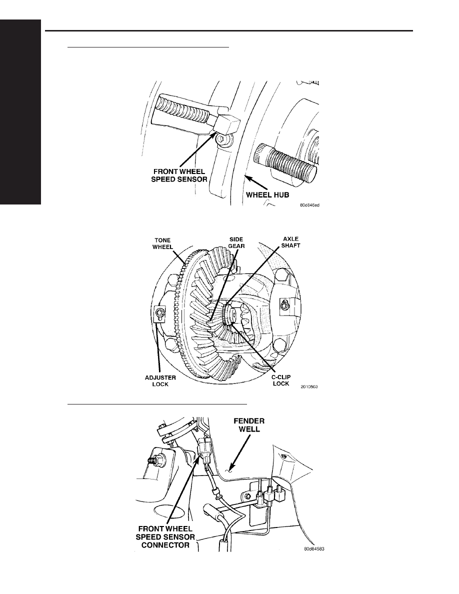
8.3
WHEEL SPEED SENSORS/TONE WHEELS
8.3.1
FRONT
8.3.2
REAR
8.4
FRONT WHEEL SPEED SENSOR CONNECTOR
C
O
M
P
O
N
E
N
T
L
O
C
A
T
I
O
N
S
66
COMPONENT LOCATIONS
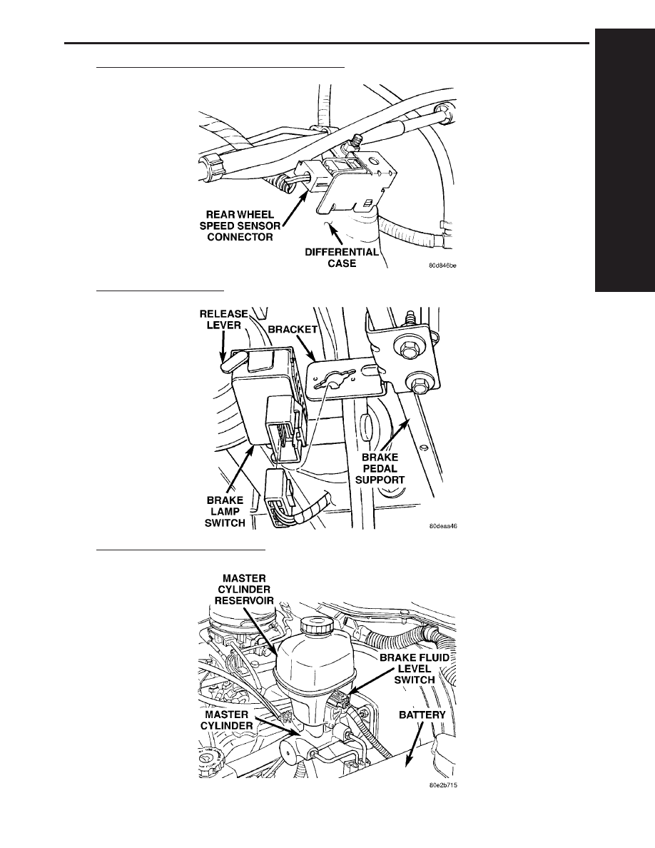
8.5
REAR WHEEL SPEED SENSOR CONNECTOR
8.6
BRAKE LAMP SWITCH
8.7
BRAKE FLUID LEVEL SWITCH
C
O
M
P
O
N
E
N
T
L
O
C
A
T
I
O
N
S
67
COMPONENT LOCATIONS
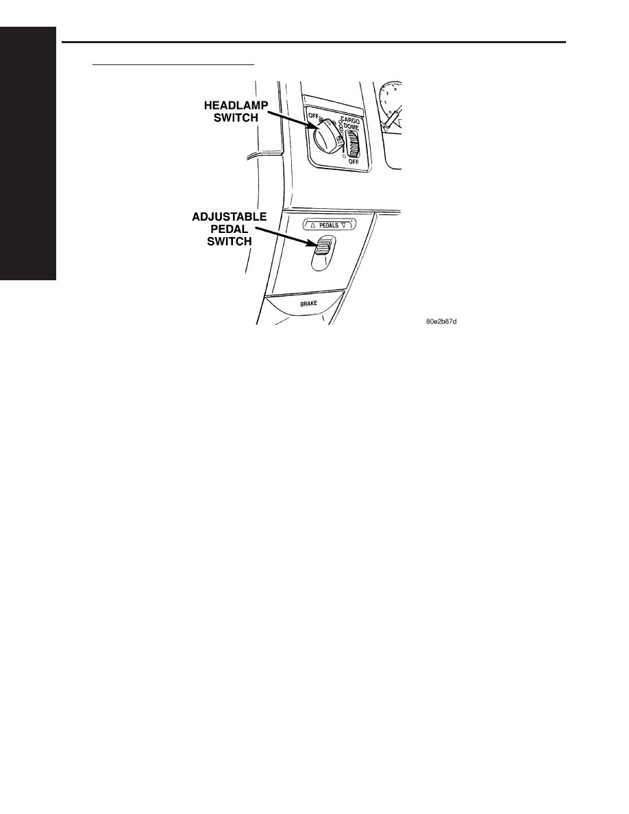
8.8
ADJUSTABLE PEDAL SWITCH
C
O
M
P
O
N
E
N
T
L
O
C
A
T
I
O
N
S
68
COMPONENT LOCATIONS
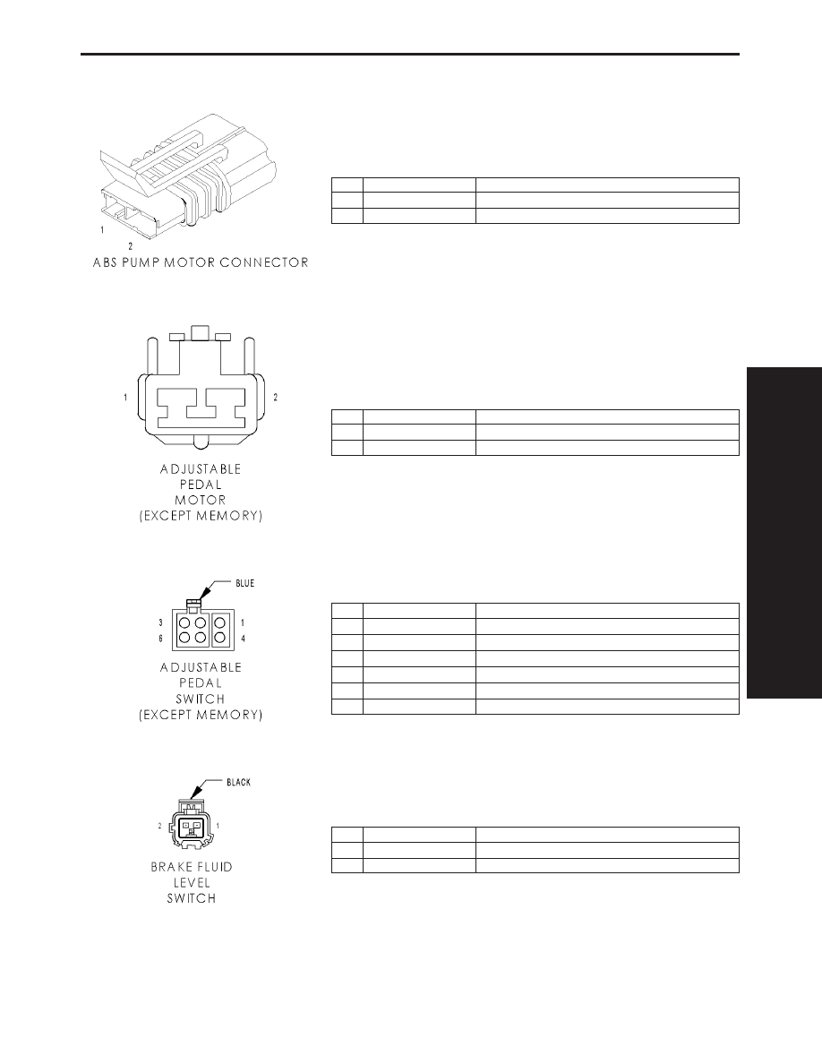
9.0
CONNECTOR PINOUTS
ABS PUMP MOTOR CONNECTOR - 2 WAY
CAV
CIRCUIT
FUNCTION
1
RD
ABS PUMP CONTROL
2
BK
GROUND
ADJUSTABLE PEDAL MOTOR (EXCEPT MEMORY) - 2 WAY
CAV
CIRCUIT
FUNCTION
1
P206 18LG/LB
ADJUSTABLE PEDALS MOTOR REVERSE
2
P205 18LG/WT
ADJUSTABLE PEDALS MOTOR FORWARD
ADJUSTABLE PEDAL SWITCH (EXCEPT MEMORY) - BLUE 6 WAY
CAV
CIRCUIT
FUNCTION
1
P206 18LG/LB
ADJUSTABLE PEDALS MOTOR REVERSE
2
A72 18RD/OR
ADJUSTABLE PEDAL RELAY OUTPUT
3
-
-
4
Z146 18BK
GROUND
5
F504 20GY/PK
FUSED IGNITION SWITCH OUTPUT (RUN)
6
P205 18LG/WT
ADJUSTABLE PEDALS MOTOR FORWARD
BRAKE FLUID LEVEL SWITCH - BLACK 2 WAY
CAV
CIRCUIT
FUNCTION
1
B20 20DG/OR
BRAKE FLUID LEVEL SWITCH SENSE
2
Z420 20BK/OR
GROUND
C
O
N
N
E
C
T
O
R
P
I
N
O
U
T
S
69
CONNECTOR PINOUTS
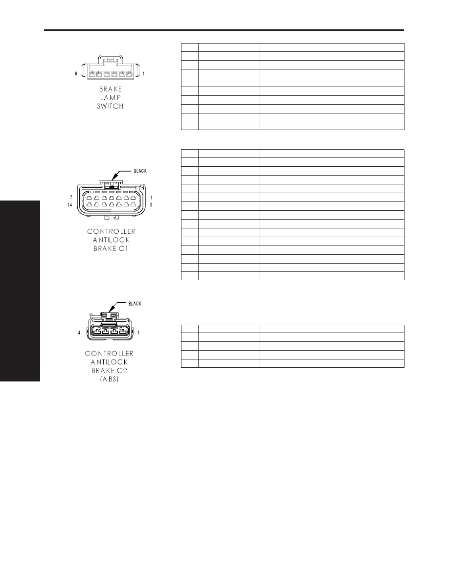
BRAKE LAMP SWITCH - 6 WAY
CAV
CIRCUIT
FUNCTION
1
A103 18GY/RD
FUSED B(+)
2
L50 18WT/TN
BRAKE LAMP SWITCH OUTPUT
3
V30 20VT/WT
S/C BRAKE SWITCH OUTPUT
3
V30 20VT/WT (5.7L)
FUSED IGNITION SWITCH (RUN-START)
4
V32 20VT/YL
SPEED CONTROL SUPPLY
4
V32 20VT/YL (5.7L)
BRAKE SWITCH NO. 2 SIGNAL
5
Z429 20BK/OR
GROUND
6
B29 20DG/WT
BRAKE SWITCH SIGNAL
6
B29 20DG/WT (5.7L)
BRAKE SWITCH NO. 1 SIGNAL
CONTROLLER ANITLOCK BRAKE C1 - BLACK 14 WAY
CAV
CIRCUIT
FUNCTION
1
B4 20DG/GY
REAR WHEEL SPEED SENSOR (+)
2
B222 20DG/WT (ETC)
VEHICLE SPEED SIGNAL NO. 2
3
D25 20WT/VT
PCI BUS
4
F500 20DG/PK
FUSED IGNITION SWITCH OUTPUT (RUN)
5
B9 20DG/LG (ETC)
LEFT FRONT WHEEL SPEED SENSOR (+)
6
Z107 12BK/DG
GROUND
7
A111 14DG/RD
FUSED B(+)
8
B3 20DG/YL
REAR WHEEL SPEED SENSOR (-)
9
B29 20DG/WT
BRAKE SWITCH SIGNAL
10
B8 20DG/TN (ETC)
LEFT FRONT WHEEL SPEED SENSOR (-)
11
B20 20DG/OR
BRAKE FLUID LEVEL SWITCH SENSE
12
B22 20DG/YL
VEHICLE SPEED SIGNAL NO. 1
13
Z127 12BK/DG (ABS)
GROUND
14
A111 14DG/RD (ABS)
FUSED B(+)
CONTROLLER ANTILOCK BRAKE C2 (ABS) - BLACK 4 WAY
CAV
CIRCUIT
FUNCTION
1
B9 20DG/LG
LEFT FRONT WHEEL SPEED SENSOR (+)
2
B8 20DG/TN
LEFT FRONT WHEEL SPEED SENSOR (-)
3
B6 20DG/WT
RIGHT FRONT WHEEL SPEED SENSOR (-)
4
B7 20DG/VT
RIGHT FRONT WHEEL SPEED SENSOR (+)
C
O
N
N
E
C
T
O
R
P
I
N
O
U
T
S
70
CONNECTOR PINOUTS
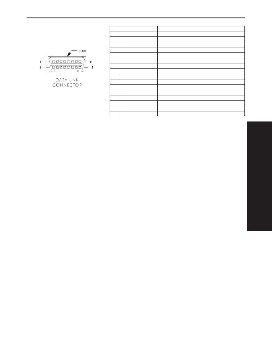
DATA LINK CONNECTOR - BLACK 16 WAY
CAV
CIRCUIT
FUNCTION
1
-
-
2
D25 20WT/VT
PCI BUS
3
-
-
4
Z11 18BK/LG
GROUND
5
Z111 18BK/WT
GROUND
6
-
-
7
D21 18WT/BR
SCI TRANSMIT (PCM)
8
-
-
9
D16 18WT/OR
SCI RECEIVE (TCM)
10
-
-
11
-
-
12
D20 20WT/LG
SCI RECEIVE (PCM)
13
-
-
14
-
-
15
D15 18WT/DG
SCI TRANSMIT (TCM)
16
A114 18GY/RD
FUSED B(+)
C
O
N
N
E
C
T
O
R
P
I
N
O
U
T
S
71
CONNECTOR PINOUTS
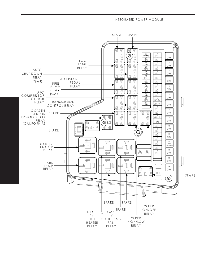
C
O
N
N
E
C
T
O
R
P
I
N
O
U
T
S
72
CONNECTOR PINOUTS
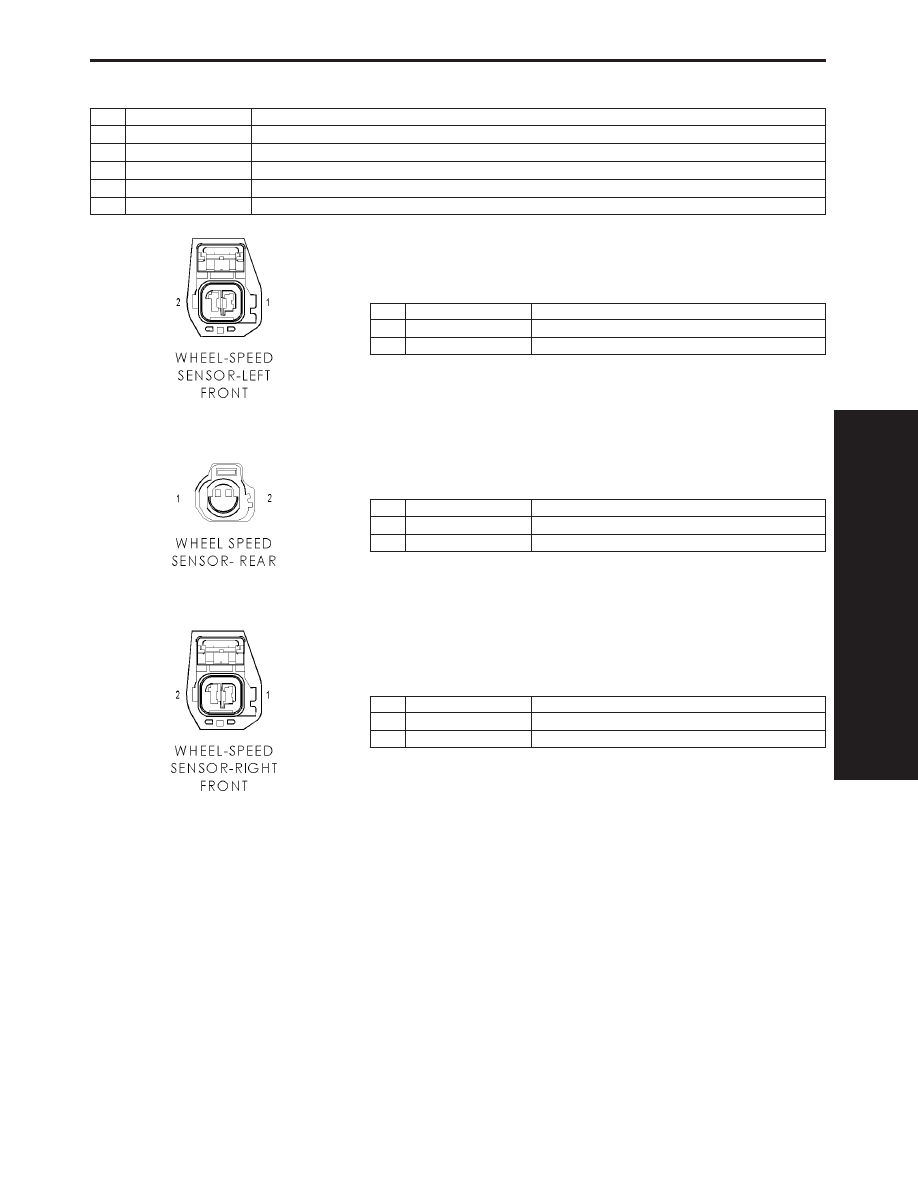
ADJUSTABLE PEDAL RELAY
CAV
CIRCUIT
FUNCTION
30
INTERNAL
FUSED B(+)
85
INTERNAL
FUSED B(+)
86
INTERNAL
ADJUSTABLE PEDAL RELAY CONTROL
87
-
-
87A
A72 18RD/OR
ADJUSTABLE PEDAL RELAY OUTPUT
WHEEL SPEED SENSOR-LEFT FRONT - 2 WAY
CAV
CIRCUIT
FUNCTION
1
B8 20DG/TN
LEFT FRONT WHEEL SPEED SENSOR (-)
2
B9 20DG/LG
LEFT FRONT WHEEL SPEED SENSOR (+)
WHEEL SPEED SENSOR-REAR - 2 WAY
CAV
CIRCUIT
FUNCTION
1
B3 18DG/YL
LEFT REAR WHEEL SPEED SENSOR SIGNAL
2
B4 18DG/GY
LEFT REAR WHEEL SPEED SENSOR 12 VOLT SUPPLY
WHEEL SPEED SENSOR-RIGHT FRONT - 2 WAY
CAV
CIRCUIT
FUNCTION
1
B6 20DG/WT
RIGHT FRONT WHEEL SPEED SENSOR (-)
2
B7 20DG/VT
RIGHT FRONT WHEEL SPEED SENSOR (+)
C
O
N
N
E
C
T
O
R
P
I
N
O
U
T
S
73
CONNECTOR PINOUTS

NOTES
74
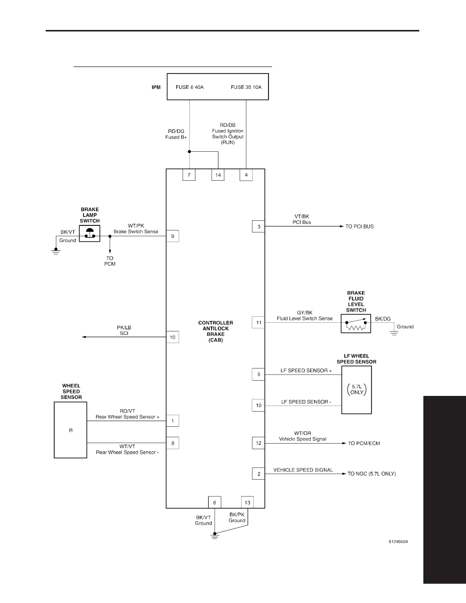
10.0
SCHEMATIC DIAGRAMS
10.1
TRW EBC 125 – CONTROLLER ANTILOCK BRAKE
S
C
H
E
M
A
T
I
C
D
I
A
G
R
A
M
S
75
SCHEMATIC DIAGRAMS
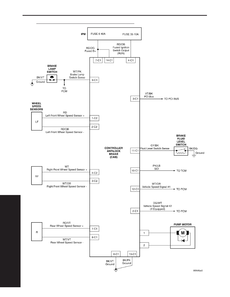
10.2
TRW EBC 325 – CONTROLLER ANTILOCK BRAKE
S
C
H
E
M
A
T
I
C
D
I
A
G
R
A
M
S
76
SCHEMATIC DIAGRAMS
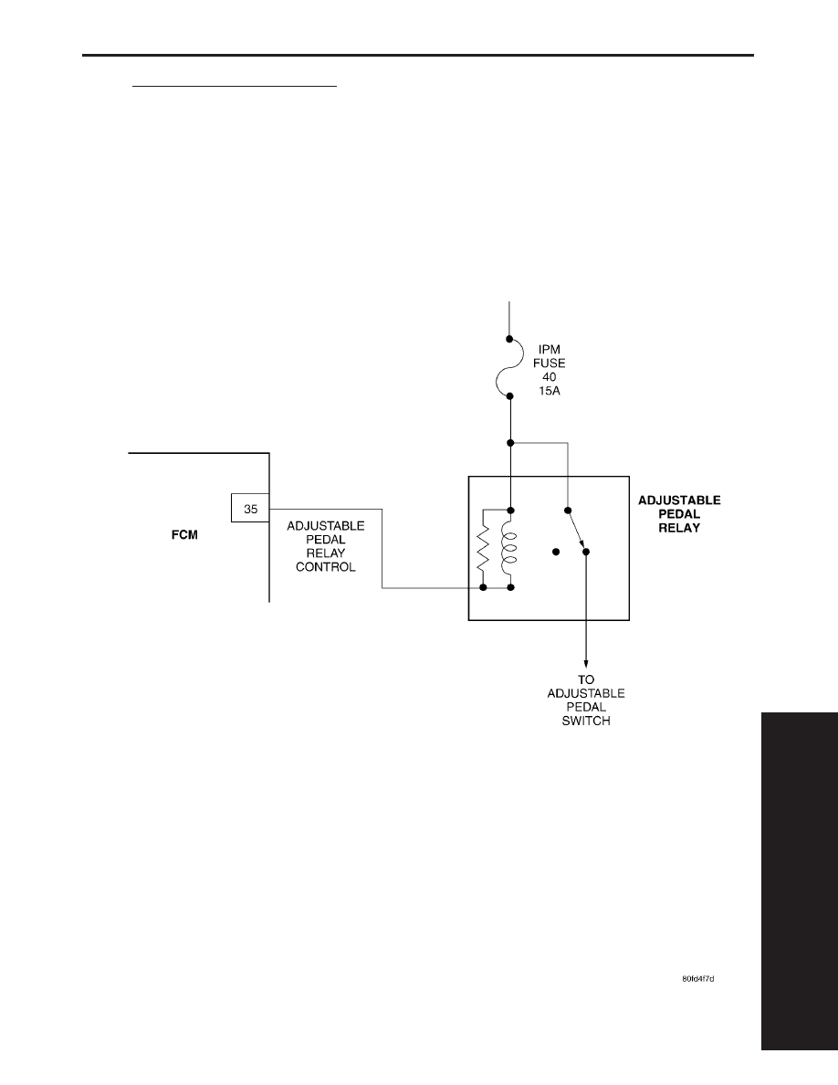
10.3
ADJUSTABLE PEDAL RELAY
S
C
H
E
M
A
T
I
C
D
I
A
G
R
A
M
S
77
SCHEMATIC DIAGRAMS

NOTES
78

DIAGNOSTIC TEST PROCEDURES — TELL US!
DaimlerChrysler Corporation is constantly working to provide the technician the best diagnostic manuals possible.
Your comments and recommendations regarding the diagnostic manuals and procedures are appreciated.
To best understand your suggestion, please complete the form giving us as much detail as possible.
Model
Year
Body Type
Engine
Transmission
Vehicle Mileage
MDH
Diagnostic Procedure
Book No.
Page
Comments/recommendations (if necessary, draw sketch)
Name
Submitted by:
Address
City/State/Zip
Business Phone #
All comments become property of DaimlerChrysler Corporation and may be used without compensation.
Dealer Technical Operations
800 Chrysler Drive
CIMS 486-02-76
Auburn Hills, MI 48326-2757
Document Outline
- DR Service Manual
- DR Gas Powertrain
- DR Body
- DR Chassis
- TABLE OF CONTENTS
- 1.0 INTRODUCTION
- 2.0 IDENTIFICATION OF SYSTEM
- 3.0 SYSTEM DESCRIPTION AND FUNCTIONAL OPERATION
- 3.1 ABS
- 3.1.1 TRW EBC 125 SYSTEM DESCRIPTION
- 3.1.2 TRW EBC 325 SYSTEM DESCRIPTION
- 3.1.3 TRW EBC 125 CONTROLLER ANTILOCK BRAKE (CAB)
- 3.1.4 TRW EBC 325 CONTROLLER ANTILOCK BRAKE (CAB)
- 3.1.5 ABS WARNING INDICATOR AND RED BRAKE WARNING INDICATOR (EBC 125 AND EBC 325)
- 3.1.6 BRAKE LAMP SWITCH CIRCUIT
- 3.1.7 BRAKE FLUID LEVEL SWITCH CIRCUIT
- 3.1.8 HYDRAULIC CONTROL UNIT
- 3.1.9 WHEEL SPEED SENSORS
- 3.1.10 4WD INPUT
- 3.1.11 DIAGNOSTIC COMMAND MODES
- 3.1.12 SELF-TEST AT IGNITION TURN ON
- 3.1.12 DRBIII DIAGNOSTIC COMMANDS
- 3.1.13 THE ON-BOARD DIAGNOSTIC SYSTEM
- 3.2 ADJUSTABLE PEDALS SYSTEM
- 3.3 USING THE DRBIII
- 3.4 DRBIII ERROR MESSAGES AND BLANK SCREEN
- 3.1 ABS
- 4.0 DISCLAIMERS, SAFETY, WARNINGS
- 5.0 REQUIRED TOOLS AND EQUIPMENT
- 6.0 GLOSSARY OF TERMS
- 7.0 DIAGNOSTIC INFORMATION AND PROCEDURES
- ADJUSTABLE PEDALS
- BRAKES (CAB)
- BODY STYLE MISMATCH - 85
- BRAKE SWITCH CIRCUIT - 81
- ECU INTERNAL FAILURE - 75
- EXCESSIVE DUMP TIME - 69
- FOUNDATION BRAKE - 78
- INTERMITTENT SIGNAL FROM LEFT FRONT SENSOR - 27
- INTERMITTENT SIGNAL FROM REAR SENSOR - 37
- INTERMITTENT SIGNAL FROM RIGHT FRONT SENSOR - 23
- LEFT FRONT SENSOR OPEN - 25
- LEFT FRONT SENSOR SHORTED - 90
- NO SIGNAL FROM LEFT FRONT SENSOR - 26
- NO SIGNAL FROM REAR SENSOR - 36
- NO SIGNAL FROM RIGHT FRONT SENSOR - 22
- REAR SENSOR OPEN - 35
- REAR SENSOR SHORTED - 93
- RIGHT FRONT SENSOR OPEN - 21
- RIGHT FRONT SENSOR SHORTED - 91
- INTERNAL MAIN RELAY OPEN - 65
- INTERNAL MAIN RELAY SHORTED - 66
- LEFT FRONT DUMP SOLENOID OPEN - 46
- LEFT FRONT DUMP SOLENOID SHORTED - 48
- LEFT FRONT ISOLATION SOLENOID OPEN - 45
- LEFT FRONT ISOLATION SOLENOID SHORTED - 47
- REAR DUMP SOLENOID OPEN - 52
- REAR DUMP SOLENOID SHORTED - 54
- REAR ISOLATION SOLENOID OPEN - 51
- REAR ISOLATION SOLENOID SHORTED - 53
- RIGHT FRONT DUMP SOLENOID OPEN - 42
- RIGHT FRONT DUMP SOLENOID SHORTED - 44
- RIGHT FRONT ISOLATION SOLENOID OPEN - 41
- RIGHT FRONT ISOLATION SOLENOID SHORTED - 43
- MISMATCHED VIN - 84
- NUMBER OF TONE RING TEETH OUT OF RANGE - 82
- PUMP MOTOR CIRCUIT OPEN - 67
- PUMP MOTOR STALLED - 68
- RAM READ/WRITE - 71
- REAR RESET SWITCH CLOSED - 63
- ROM CHECKSUM - 72
- SYSTEM CONTROL MODE TIMEOUT - 74
- SYSTEM OVER / UNDER VOLTAGE - 96
- TIRE REVS PER MILE OUT OF RANGE - 83
- WATCHDOG - 73
- WHEEL SPEED MISMATCH - 38
- *REPLACING THE CONTROLLER ANTILOCK BRAKE
- *VEHICLE SPEED SIGNAL OUTPUT
- COMMUNICATION
- VERIFICATION TESTS
- 8.0 COMPONENT LOCATIONS
- 9.0 CONNECTOR PINOUTS
- ABS PUMP MOTOR CONNECTOR - 2 WAY
- ADJUSTABLE PEDAL MOTOR (EXCEPT MEMORY) - 2 WAY
- ADJUSTABLE PEDAL SWITCH (EXCEPT MEMORY) - BLUE 6 WAY
- BRAKE FLUID LEVEL SWITCH - BLACK 2 WAY
- BRAKE LAMP SWITCH - 6 WAY
- CONTROLLER ANITLOCK BRAKE C1 - BLACK 14 WAY
- CONTROLLER ANTILOCK BRAKE C2 (ABS) - BLACK 4 WAY
- DATA LINK CONNECTOR - BLACK 16 WAY
- ADJUSTABLE PEDAL RELAY
- WHEEL SPEED SENSOR-LEFT FRONT - 2 WAY
- WHEEL SPEED SENSOR-REAR - 2 WAY
- WHEEL SPEED SENSOR-RIGHT FRONT - 2 WAY
- 10.0 SCHEMATIC DIAGRAMS
- COMMENTS
Wyszukiwarka
Podobne podstrony:
18617 dr chassis sgmldiag
7 zapalenie wewnetrznych narzadow plciowych dr pawlaczyk
higiena dla studentów 2011 dr I Kosinska
Krwawienie dr
zdarzenia masowe, Dr I Baumberg 1 1
przykładowa prezentacja przygotowana na zajęcia z dr inż R Siwiło oceniona
wykład dr szaroty pojęcia
Panic dr Runge (1)
dr M Latos Miłkowska Upadłość i likwidacja pracodawcy
Metodologia badań z logiką dr Karyłowski wykład 7 Testowalna w sposób etycznie akceptowalny
żywienie dzieci Dr Macheta
Psychologia osobowości dr Kofta wykład 9 Poznawcza teoria Ja
CHF dr gębalska 17 01 03
Psychologia osobowości dr Kofta wykład 4 Osobowość w świetle teorii uczenia sie
wykład dr Steplewska uklad limfatyczny1 bez zdjęć
philips chassis l6 1
więcej podobnych podstron