
CONTENTS PAGE
Safety Instructions 2
Technical Specifications 3
Block Diagram 4
Pin Voltages of IC’s 5
Oscillograms 8
Electrical and Service Adjustments
12
Part List
15
Circuit Diagrams
Attached
SAFETY INSTRUCTIONS
GENERAL GUIDELINES
1. It is advised to insert an isolation transformer
in the AC supply before servicing a hot
chassis.
2. Potentials as high as 33KV are present when
this receiver is in operation. Operation of the
receiver without the rear cover involves the
danger of a shock hazard from the receiver
power supply. Servicing should not be
attempted by any one who is not
competent with the precautions necessary
when working on the high voltage
equipment. Always discharge the anode of
the tube.
3. When servicing observe the original lead
dress in the high voltage circuits. If a short
circuit is found, replace all the parts which
have been overheated or damaged by the
short circuit.
4. Always use the manufacturer’s replacement
safety components. The critical safety
components marked with
on the
schematics diagrams should not be
replaced by other substitutes. Other
substitute may create the electrical shock,
fire or other hazards. Take attention to
replace the spacers with the originals.
Furthermore where a short circuit has
occurred, replace those components that
indicate evidence of overheating.
5. After servicing, see that all the protective
devices such as insulation barriers, insulation
papers, shields and isolation R-C
combinations are correctly installed.
6. When the receiver is not being used for a
long time of period of time, unplug the
power cord from the AC outlet.
7. After servicing make the following leakage
current checks to prevent the customer
from being exposed to shock hazard.
LEAKAGE CURRENT COLD CHECK
1. Unplug the AC cord and connect a jumper
between the two prongs of the plug.
2. Turn the receiver’s power switch on.
3. Measure the resistance value with an
ohmmeter, between the jumpered AC plug
and each exposed metallic cabinet part on
the receiver, such as screw heads, aerials,
connectors, control shafts etc. When the
exposed metallic part a return path to the
chassis the reading should be between
4Mohm and the 20Mohm. When the
exposed metal does not have a return path
to the chassis, the reading must be infinite.
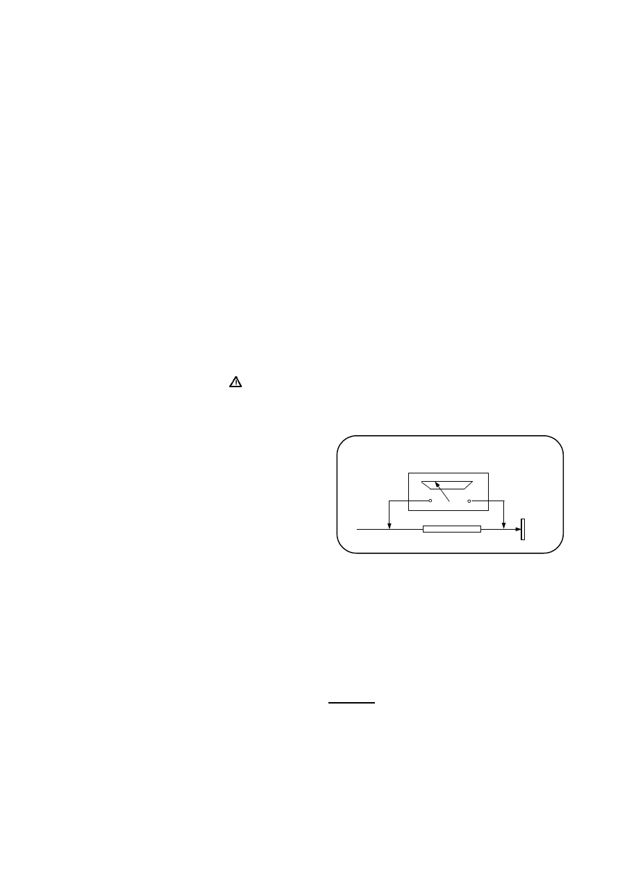
LEAKAGE CURRENT HOT CHECK
1. Plug the AC cord directly in to the AC
outlet. Do not use an isolation transformer
for this check.
2. Connect a 2Kohm 10W resistor in series with
an exposed metallic part on the receiver
and an earth, such as a water pipe.
3. Use an AC voltmeter with high impedance
to measure the potential across the resistor.
4. Check each exposed metallic part and
check the voltage at the each point.
5. Reverse the AC plug at the outlet and
repeat each of the above measurements.
6. The potential at the any point should not
exceed 1.4 Vrms. In case a measurement is
outside the limits specified, there is the
possibility of a shock hazard, and the
receiver should be repaired and rechecked
before it is returned to the customer.
HOT CHECK CIRCUIT
AC-Voltmeter
TO INSTRUMENTS
EXPOSED
METALLIC PARTS
Water pipe
(earth)
2 K Ohm
Figure 1
X-RAY RADIATION WARNING
The primary source of X-ray radiation in this receiver
is the picture tube. The chassis is specially
constructed to limit X-ray radiation. For continued
X-ray radiation protection, replace the tube with
the same type of the original one.
CAUTION
AFTER REMOVAL OF THE ANODE CAP, DISCHARGE
THE ANODE OF THE PICTURE TUBE AND THE ANODE
CAP TO THE METAL CHASSIS, CRT SHIELD, OR THE
CARBON PAINTED ON THE CRT WITH A HIGH
VOLTAGE PROBE AND MULTIMETER (SELECT VDC)
AND THEN SHORT CIRCUIT DIRECTLY TO DISCHARGE
COMPLETELY.

TECHNICAL SPECIFICATIONS
Power source:
220-240V AC, 50-60Hz
Power consumption (max.) : 115 W
20”, 21” (110W for 21” PF)
Standby power consumption :
4 W
Aerial impedance :
75Ohm, coaxial type
Receiving system
1
: PAL
BG
PAL SECAM BG
PAL SECAM BG DK
PAL SECAM BG LL’
PAL
I
Receiving channels:
VHF BAND I
CH2-4
VHF BAND III
CH5-12
CABLE
TV
S1-41
UHF
BAND
CH21-69
Audio outputs :
2 x 7W RMS at %10 THD
High Voltage :
25 ± 0.5 KV
20”, 21”
Focus voltage :
%25.6 ± %38 of EHT
Grid 2 voltage :
0-1400 V
Heater voltage :
6.2 ± 0.2 Vrms
Video/Audio Terminals :
AV1 IN
Video : 1 Vpp,75 Ohm
Audio : 0.5 Vrms, >10 Kohm
RGB
AV1OUT
Video : 1 Vpp, 75 Ohm
Audio : 0.5 Vrms, <1 Kohm
AV2 IN (optional)
Video : 1 Vpp,75 Ohm
Audio : 0.5 Vrms, >10 Kohm
AV2 OUT (optional)
Video : 1 Vpp, 75 Ohm
Audio : 0.5 Vrms, <1 Kohm
AV2 IN (RCA, optional)
Video : 1 Vpp, 75 Ohm
Audio : 0.5 Vrms, >10 Kohm
Operating temperature :
0-45 Degrees
Safety :
IEC 65 /BS P2N
X-Ray radiation :
ACC. IEC 65/BS P2N
1
: TV set is produced to receive “one” of these colour and sound systems.
IC316 MSP34X
0G
Audio Pr
ocessor
Mono i
n /
Au
d
o
ut
RGB
T701
, T703
,
T705
CRT
Modu
le
T702
, T704
,
T706
H-O
ut
H-S
yn
c
/L
FB
48
49
47
20
/13
SI
F
1-
2
44
7-
6
PI
F
8
IC101 STV224X
Horizont
al
Deflect
ion
BU808
DFI
220
V A
C
in
5V
B
5V
A
-13V
+1
3V
U
1=1
14
V
, 33
V
IC
501
TDA8174
Ve
rt
ic
a
l
Deflect
.
V-L
in
8
Scart
1
IR
Rec
e
iv
e
r
Keyboard
V-
O
ut
H-s
yn
c
V-
sy
nc
IC401 EE
PROM
On
/Off
(S
ta
nd
b
y)
To I
C
901
53
20
19
33
40
41
14
7
56
IC 402 ST92195
Microcontroller
CV
BS
-T
XT
L/
L’
OS
D/TX
T
RGB out +
Fast B
la
nk
ing
AG
C
SC
L
SD
A
IF
1
IF
2
Tuner
IC901
TDA16847
Po
w
e
r Supply
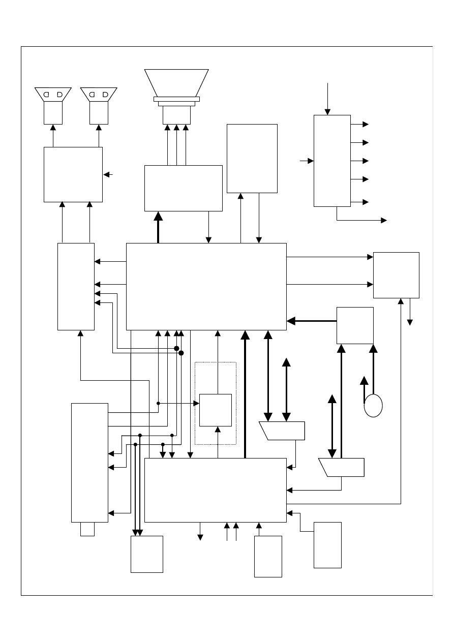
16.1 Block Diagram
R
G
B
ou
t
13
8
8V
A
42
V-A
m
p
I2C 51-
52
91
0
58
55
In
tr
/
QSS
11
29
28
IC317
TDA8944
J
Au
dio
Am
p.
Rig
h
t
HP
Left HP
CP
T
Le
ft
Ri
g
ht
A
ud
io I
n/Out
IC
316
45
T105,
T109
LL’
Sw
itch
On/off (S
ta
nd
b
y)
fr
om I
C
401
34
-37
V-S
ync to
IC
402
Bl
ack
33
30
-32
Vi
d
e
o
In
/O
ut
15
-18
24
MS
P Re
set
43
Scart
2
55
8
CV
BS
/C
hr
o
m
a
IC
316
Au
d
io
In
/O
ut
IC102 Source Selec
t
22
/23
SV
H
S
Lum/Chroma
IC
316
Au
d
io
9/
12
6/
8
1
7/
14
1/
4
M
ute
(f
ro
m p
in 49
of I
C
402
)
10
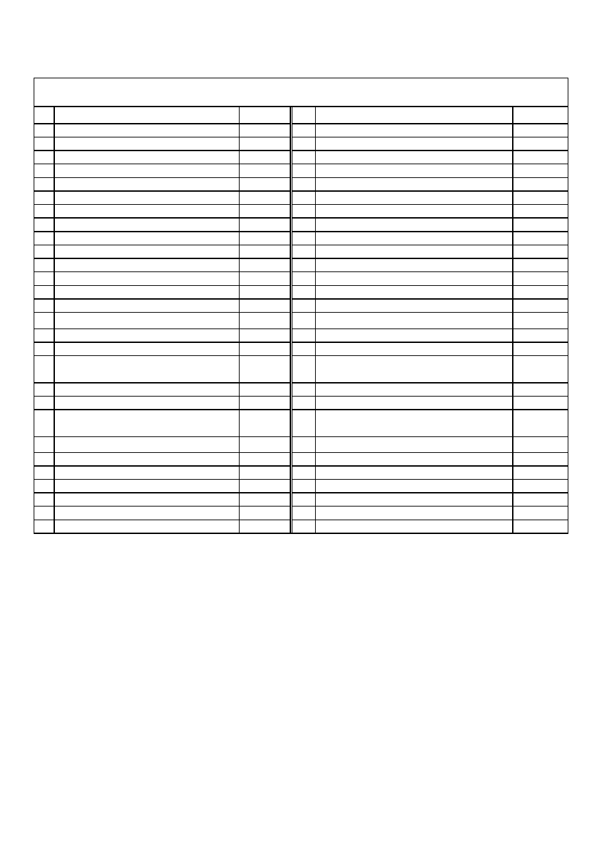
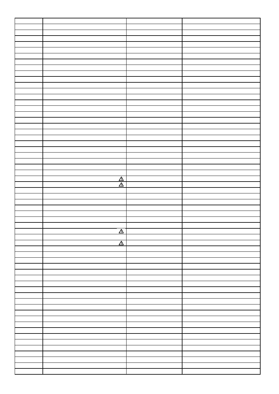
PIN VOLTAGES OF IC'S
Pin
Connection
V DC (*)
Pin
Connection
V DC (*)
1 Sound IF Input 1
1,0
29 Not connected
3,9
2 Sound IF Input 2
1,0
30 Blue Output
2,3
3 AGC SIF Capacitor
0,1
31 Green Output
2,2
4 IF Voltage Reference Filtering
3,2
32 Red Output
2,3
5 AGC PIF Capacitor
0,1
33 Cathode Current Measurement Input
4,2
6 Picture IF Input 1
2,5
34 OSD Blue Input
4,7
7 Picture IF Input 2
2,5
35 OSD Green Input
4,8
8 AGC Tuner Output
4,6
36 OSD Red Input
4,7
9 IF PLL Filter
1,2
37 OSD Fast Blanking
0,2
10 IF Ground
0,0
38 Cloche Filter Tuning Capacitor
0,1
11 AM/FM Mono Sound Output
4,2
39 3.5X MHz Crystal
0,4
12 5 V IF Supply
5,1
40 4.43 MHz Crystal
-
13 Internal CVBS Output
3,2
41 Chroma PLL Filter
-
14 External Audio Input
2,5
42 Vertical Amplitude DAC Output
4,0
15 LC Input 1
4,0
43 Chroma/Scanning Ground
0,0
16 LC Input 2
4,0
44 Second Video Switch Output
4,1
17 Video/Luma Supply Voltage (8 V)
8,1
45 Chroma/Scanning Power Supply (8V)
8,1
18 Internal Video Input
3,7
46 Beam Current Limiter Control Voltage and
Safety Input (XRAY)
6,8
19 Video/Luma Ground
0,0
47 Vertical Output Pulse
4,0
20 External Video Input
3,2
48 Horizontal Output Pulse
1,4
21 Black Stretch Capacitor
2,8
49 Line Flyback Input and Super-sandcastle Output
0,7
22 Y/CVBSIN3 Y(SVHS) or CVBS3 External Input
3,2
50 Scanning PLL Filter
4,1
23 Chroma (SVHS) Input
1,8
51 SCL I2C Bus Clock Input
see osc.
24 Automatic RGB Peak Regulation
5,0
52 SDA I2C Bus Data Input
see osc.
25 External Blue Input
2,5
53 Digital Supply Voltage (5 V)
5,2
26 External Green Input
1,7
54 Digital Ground
0,0
27 External Red Input
2,5
55 Main Audio Output
4,0
28 External Fast Blanking Input
0,0
56 FM Demodulation Capacitor
1,5
IC101 (STV2246)
BUS CONTROLLED MULTISTANDARD ONE CHIP TV PROCESSOR
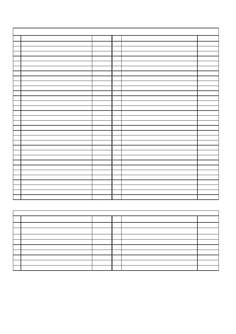
Pin
Connection
V DC
Pin
Connection
V DC
1 Not connected
2,3
33 Scart 2 sound output (R)
3.7
2 Gnd
0,0
34 Scart 2 sound output (L)
3.7
3 Gnd
0,0
35 Reference analog ground
0,0
4 Digital control input/output
0,0
36 Scart 1 sound output (R)
3.7
5 Digital control input/output
0,0
37 Scart 1 sound output (L)
3.7
6 Gnd
0,0
38 Volume capacitor Headphone
7,1
7 Standby
(in normal operation it must be high)
4.9
39 Analog Supply High Voltage (8V)
8,0
8 Not connected
4.9
40 Volume capacitor Speaker
7,1
9 SCL
see osc.
41 Ground for Analog Power Supply High Voltage
0,0
10 SDA
see osc.
42 Internal Analog Reference Voltage
3.7
11 Not connected
0,5
43 Scart 4 input (L)
3.7
12 Not connected
0,5
44 Scart 4 input (R)
3.7
13 Not connected
0,5
45 Analog Shield Ground
0,0
14 Not connected
0,5
46 CINCH - sound input (L)
3.7
15 Not connected
0,5
47 CINCH - sound input (R)
3.7
16 Not connected
0,5
48 Analog Shield Ground
0,0
17 ADR Bus Clock Output
0,5
49 Scart 2 sound input (L)
3.7
18 Digital Circuitry Supply Voltage
4.9
50 Scart 2 sound input (R)
3.7
19 Digital Circuitry Supply Ground
0,0
51 Analog Shield Ground
0,0
20 Not connected
0,5
52 Scart sound 1 input (R)
3.7
21 Not connected (Ground)
0,0
53 Scart 1 sound input (L)
3.7
22 Not connected (Ground)
0,0
54 A/D converter ref. Voltage
2.5
23 Not connected (Ground)
0,0
55 Mono sound input
3.7
24 MSP RESET input
5,1
56 Ground for Analog Power Supply Voltage
0,0
25 Headphone sound output (R)
0,1
57 Analog Power Supply Voltage (5V)
4.9
26 Headphone sound output (L)
0,1
58 IF input 1
1.5
27 Reference analog ground
0,0
59 IF Common reference for IF IN1/IN2
1.5
28 Speaker output (R)
0.1-2.1
60 IF input 2
0,0
29 Speaker output (L)
0.1-2.1
61 Factory test mode enable (ground)
0,0
30 Not connected
0.1-2.1
62 Crystal oss. input
2.3
31 Not connected
0.1-2.1
63 Crystal oss. output
2.3
32 Not connected
0.1-2.1
64 Not connected (Ground)
0,0
Pin
Connection
V DC
Pin
Connection
V DC
1 negative loudspeaker terminal 1
6,1
10 mode select.input (standby,mute,operating)
0,0
2 ground channel 1
0,0
11 half supply voltage decoupling
(ripple rejection)
6,2
3 supply voltage channel 1
12,4
12 positive input 2
6,2
4 positive loudspeaker terminal 1
6,1
13 DC gain control
0,0
5 not connected
0,0
14 negative loudspeaker terminal 2
6,1
6 positive input 1
6,2
15 ground channel 2
0,0
7 signal ground
0,0
16 supply voltage channel 2
12,4
8 negative input 1
6,2
17 positive loudspeaker terminal 2
6,2
9 negative input 2
6,2
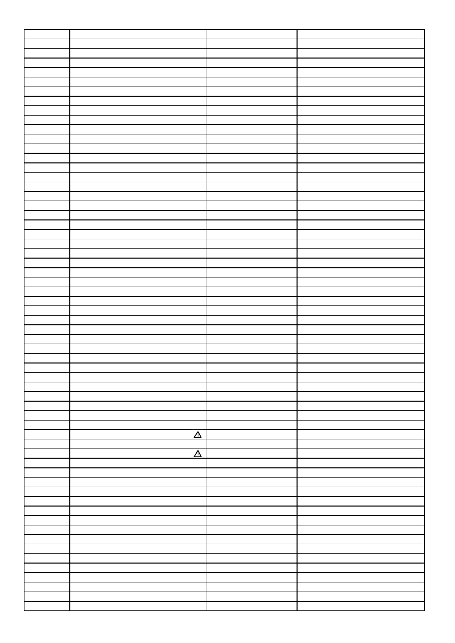
IC316 (MSP 34XXG)- MULTI STANDARD SOUND PROCESSOR
IC317 (TDA 8944J) Audio Output IC
Pin
Connection
V DC (*)
Pin
Connection
V DC (*)
1 Infra red input
4,9
29 Analog pin for TXT
2,0
2 Reset
4,3
30 Not connected
1,0
3 Not connected
0,0
31 Analog power supply for PLL (5V)
4,9
4 Not connected
0,0
32 Not connected
4,8
5 Not connected
0,0
33 CVBS input for TXT
0,5
6 Not connected
0,0
34 CVBS input for TXT
1,7
7 Not connected
0,0
35 Analog circuit ground
0,0
8 Local keyboard input
4,9
36 Digital circuit ground
0,0
9 Not connected
0,0
37 Analog pin for OSD
0,0
10 Not connected
0,0
38 Analog pin for OSD
1,9
11 Not connected
0,0
39 Analog power supply (5V)
4,9
12 Not connected
0,0
40 Horizontal sync for OSD
0,7
13 Used for factory mode
4,9
41 Vertical sync for OSD
0,2
14 Not connected
0,0
42 Not connected
0,2
15 Blue output for OSD and TXT
0,7
43 Not connected
5,2
16 Green output for OSD and TXT
0,7
44 Not connected
0,0
17 Red output for OSD and TXT
0,7
45 LL' select output
4,8
18 Fast Blanking for OSD and TXT
0,0
46 Not connected
0,1
19 SDA I2C Bus Data Input
see osc.
47 Vertical linearity output
0,8
20 SCL I2C Bus Clock Input
see osc.
48 Standby/Mute
5.0 (0.2)
21 Supply Voltage (5V)
4,9
49 Standby/Mute
5.0 (0.2)
22 Not connected
0,9
50 Oscillator out
2,3
23 Ground
0,0
51 Oscillator in
2,4
24 Ground
0,0
52 Not connected
0,1
25 Analog Vdd of PLL
-
53 On/Off (standby activate/deactivate)
0.2 (2.8)
26 Testpins:must be tied to pin 25
-
54 Not connected
0,1
27 Analog pin for OSD
1,7
55 Not connected
0,0
28 Not connected
4,8
56 Status signal input of Scart pin 8
0,0
Pin
Connection
V DC
Pin
Connection
V DC
1 Power output
13,4
7
Ramp generator
5,5
2 Output stage Vs
27,6
8
Buffer output
6,4
3 Trigger input
4,0
9
Inverting input
4,5
4 Height adjustment
6,8
10 Vs
27,6
5 Not connected
4,5
11 Flyback generator
1,3
6 Ground
0,0
Pin
Connection
V DC (*)
Pin
Connection
V DC (*)
1 Off time circuit (for standby frequency)
2.4 (0.4)
8
Power measurement output
1.5 (2.4)
2 Primary Current Simulation and Startup
1.9 (10.9)
9
Reference Ref. Voltage (5V)
4.9 (1.1)
3 Regulation and Zero Crossing Input
2.6 (0.3)
10 Fault Comparator 1 (not used)
0,0
4 Soft-Start and Regulation Capacitor
3.7 (0.3)
11 Primary Voltage Check
1.7 (2.5)
5 Opto Coupler Input (not connected)
4.9 (0.8)
12 Ground
0,0
6 Fault Comparator 2 (not used)
0,0
13 Output
4.0 (0.4)
7 Synchronization Input (for fixed freq.)
4.9 (1.1)
14 Supply Voltage
13.6 (11.7)
(*)
IC901 (TDA16847) Power Supply IC
Standby measurement values are given in parenthesis
IC402 (ST92195B)
MICRO CONTROLLER WITH OSD AND TELETEXT
IC501 (TDA8174) Vertical Deflection Output IC
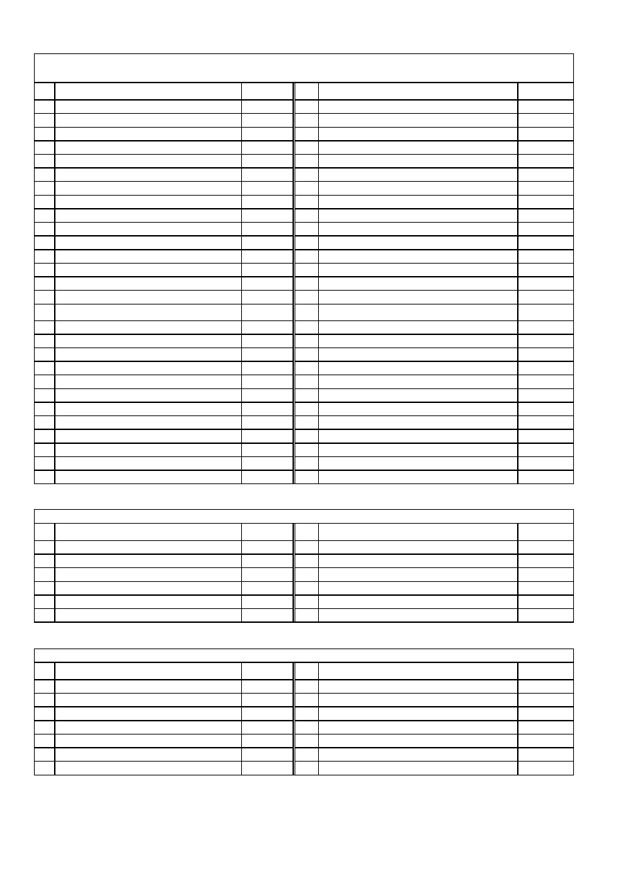
Note: TV is connected to a patern generator (Colour bar, sound 1 kHz).
IC101 (STV224X)
WAVEFORMS OF SOME IC PINS
Pin 11
1V/div, 100 usn/div, Vpp=1.6 V
Pin 30
1V/div, 100 usn/div, Vpp=3.7 V, 15625 Hz
Pin 31
1V/div, 100 usn/div, Vpp=3.7 V, 15625 Hz
Pin 32
1V/div, 100 usn/div, Vpp=4.5 V, 15625 Hz
Pin 34 (OSD Off)
1V/div, 20 usn/div, Vpp=1 V, 15625 Hz
Pin 34 (OSD On)
1V/div, 20 usn/div, Vpp=1 V, 15625 Hz
Pin 37 (OSD On)
1V/div, 20 usn/div, Vpp=2.51 V, 15625 Hz
Pin 44
1V/div, 20 usn/div, Vpp=2.3 V, 15625 Hz
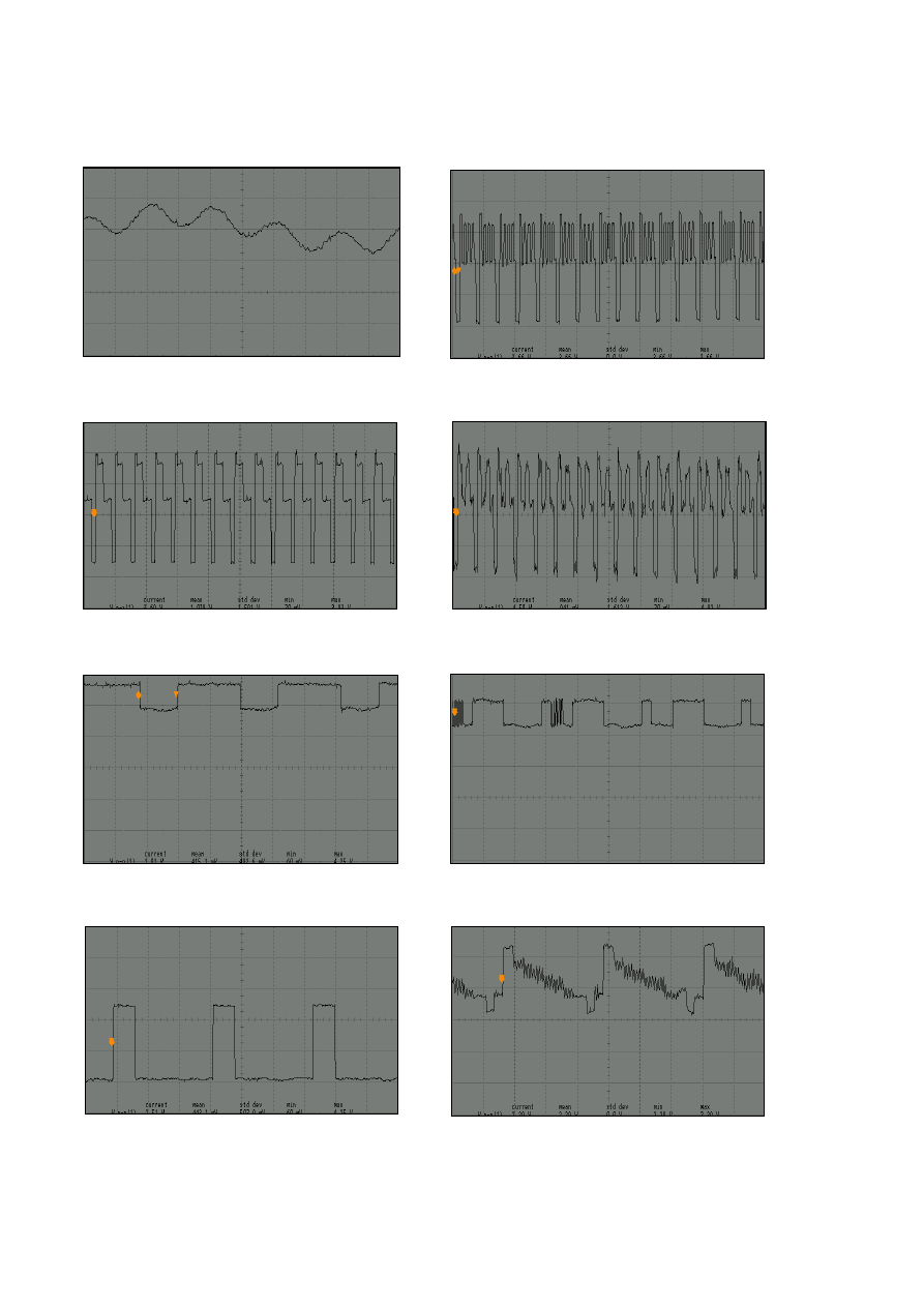
IC101 (STV224X)
IC316 (MSP34X0G)
IC402 (ST92195B)
Pin 19
1V/div, 20 usn/div, Vpp=5.2 V
Pin 20
1V/div, 20 usn/div, Vpp=4.9 V, 15625 Hz
Pin 55
200mV/div, 20 msn/div, Vpp=0.7 V
Pin 49
1V/div, 10 usn/div, Vpp=3.9 V, 15625 Hz
Pin 28
500mV/div, 50 usn/div, Vpp=1.5 V, 5kHz
Pin 47
1V/div, 10 msn/div, Vpp=6.0 V, 50 Hz
Pin 48
1V/div, 10 usn/div, Vpp=3.1 V, 15625 Hz
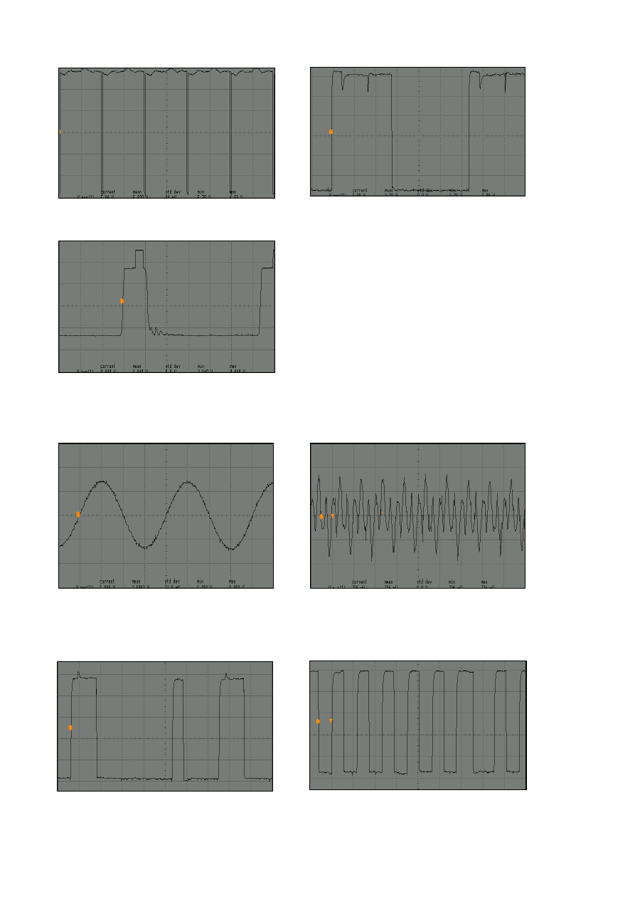
IC501 (TDA8174)
T551
Base
500mV/div, 10 usn/div, Vpp=1.5V, 15625 Hz
Collector
1 V/div, 20 usn/div, Vpp=4.7V, 15625 Hz
Pin 7
2V/div, 10 msn/div, Vpp=8.1 V, 50 Hz
Pin 47
1V/div, 20 usn/div, Vpp=5.9 V, 15625 Hz
Pin 2
5V/div, 10 msn/div, Vpp=26.7 V, 50 Hz
Pin 40
1V/div, 20 usn/div, Vpp=5.9 V, 15625 Hz
Pin 41
1V/div, 10 msn/div, Vpp=5.7 V, 50 Hz

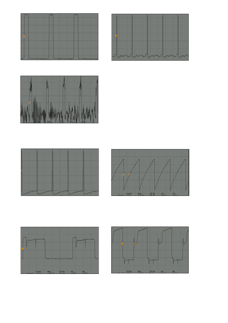
T552
Base
Collector
2 V/div, 20 usn/div, Vpp=10V, 15625 Hz
200 V/div, 20 usn/div, Vpp=932V, 15625 Hz
1. ELECTRICAL ADJUSTMENTS
1.1 Supply Voltage Adjustment
Connect a digital voltmeter to the cathode of diode D950 at the AV mode of the TV and set the
screen voltage to the minimum with the screen potentiometer. Adjust the main supply voltage (B+)
with P901 potentiometer to the following value (after supply adjustment, readjust Screen and focus
voltage).
20”
: 119 VDC (for A48ECR43X51)
21”
: 114 VDC (for A51EER33X41)
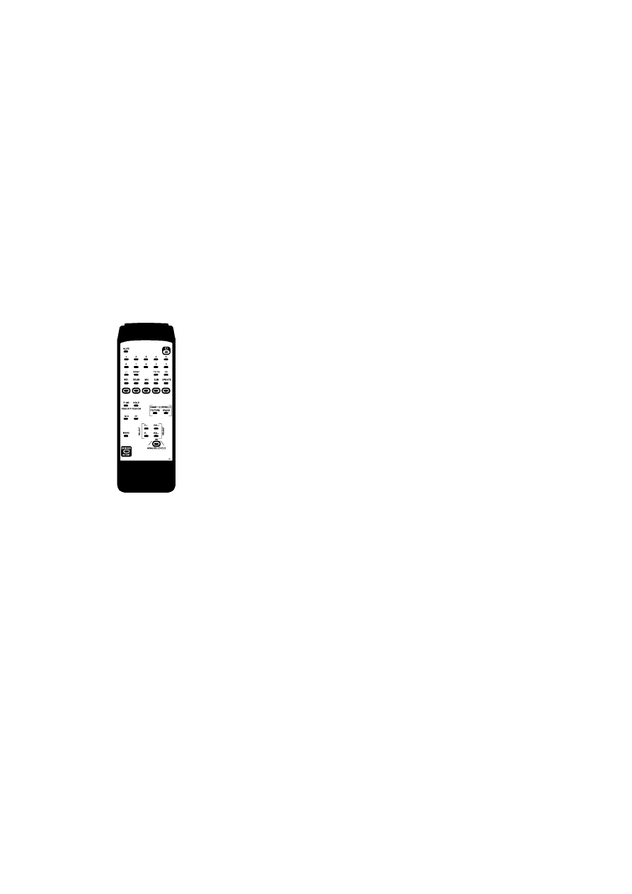
2. SERVICE ADJUSTMENTS
You need the special service remote control to enter and exit the service menu of the TV (you can
order it from the manufacturer). All buttons of the Service RC are same with the user remote control,
only service menu In / Out is added to it (please see the picture below).
Navigation
Service In/Out : Enters to / exits from the Service Menu
P+ / P-
: Moves upward / downward inside the menu
V+ / V-
: Changes the values or options
2.1 IF Adjustments
2.1.1 PAL SECAM BG/DK/I
• Supply a 471.25 MHz BG system colour bar RF signal to the set by a pattern generator.
• Find this signal in “setup” menu (C21).
• In order to deactivate AFT loop, shift value of “fine tuning” from central point by one unit and
then shiftback to the central point again (2 small vertical lines are seen in the scale on central
point).
• Store the channel by selecting “Store” and pressing “OK” button.
• Switch on the Service Menu with the Service RC.
• Check that value of “VCO C” is “07”.
• Adjust the coil LC100 until the colour of “:” sign turns red (“<” and “>” are white).
• Check that value of “VCO F” is “63”.
• Adjust the coil LC100 until the colour of “:” sign turns red (“<” and “>” are white).
• Exit from the service menu with the Service RC.
2.1.2 SECAM L/L’ (if available)
• Supply a 55.75 MHz, L’ system colour bar RF signal to the set by a pattern generator.
• Find this signal in “setup” menu (C02).
• In order to deactivate AFT loop, shift value of “fine tuning” from central point by one unit and
then shiftback to the central point again (2 small vertical lines are seen in the scale on central
point).
• Store the channel by selecting “Store” and pressing “OK” button.
• Switch on the Service Menu with the Service RC.

• Change the value of “VCO C L” , until the colour of “:” sign turns red (“<” and “>” are white).
• Change the value of “VCO F L” , until the colour of “:” sign turns red (“<” and “>” are white).
• Exit from the service menu with the Service RC.
2.2 AGC Adjustment
• Apply a signal with amplitude 70±1 dBuV to the antenna input of TV with a pattern generator
(switch sound carrier to Off and switch “Video Ext” to On).
• Switch on the Service Menu with the Service RC and find the “AGC1” with P+ / P- buttons.
• Measure the amplitude of 38.9 MHz sinusoidal signal on pin 11 (IF2) of Tuner with an
oscilloscope.
• Adjust “AGC1” to get 540 ± 20 mVpp.
• Add 5 to “AGC1” value and change “AGC2” to this value.
• Exit from the service menu with the Service RC.
2.3 Screen Adjustment
• Switch to AV mode.
• Adjust the Screen potentiometre until the voltage across the pin of R727 (that is connected
CRT cathode) and ground is 170±3 VDC (For 20”Ekranas, 21” GS7 or 21” Pure Flat CPT’s,
adjustment value is 160±3 VDC ).
2.4 White Balance Adjustment
• Apply a white pattern with a pattern generator to the antenna input.
• Enter the Service Menu with the Service RC and select “BLUE” option with P+ / P- buttons and
change its value to “31” with V+ / V- button.
• Adjust “RED” and “GRN” for white balance.
• Adjust “RED BIAS” and “GRN BIAS” for red and green cut off (There is no blue cut off
adjustment).
• If white balance can not be adjusted properly change “BLUE” value.
• Exit from Service menu.
2.5 Geometry Adjustments
• Apply the cross hatch pattern with a pattern generator to the antenna input.
• Enter Service Menu with Service RC.
• Adjust Vertical Amplitude with “VAMP1 4/3 50Hz” option.
• Set “VAMP2 16/9 50Hz” , “VAMP3 4/3 60Hz” and “VAMP4 16/9 60Hz” values according to
formulas in section 2.7 Factory Settings for Service Mode.
• Adjust vertical position with “VSHT”, vertical linearity with “VLIN” , horizontal position with
“HSHT” and vertical position of Teletext with “TXT VPOS”.
• Exit from the Service Menu.
Note that: There is no horizontal width adjustment in this chassis. It can be adjusted by changing
power supply voltage in the interval of -1 and +1 V.
2.6 Feature Options
TUNER
: Panasonic1 (ENV57D44G3), Panasonic2 (ENV57D60G3), Phillips, Sharp, Temic
SSTD
: BG, I, BG+DK, BG + L
NICAM
: NICAM On (available), NICAM Off
VIR.DOLBY
: Yes (available), No
XTAL
: 1 (4,43), 2 (4,43-3,58) (NTSC Playback available)
APPL
: INTERCAR (Intercarrier, all versions except Secam LL’), QSS (Secam LL’)
OSD CONTR : On (OSD level control is On), Off
BLUE SCRN
: On (Blue background is On), Off
APR
: On (Max. RGB level control is On), Off
COFF BLNK
: On (Auto cut off stabilization control is On), Off
AM SND
: MSP34XX, STV224X
HEAD
: Yes (Headphone available), No
FASTTEXT
: Yes (available), No

NUM.OF AV
: Please see Table 1
AV2
: Please see Table 1
STD-BY
: ON (Default, Automatic switch off is active), OFF (can be used during repair)
KEYBOARD
: 3 (3-button version), 4 (4-button version)
NUM.OF
AV
AV2
1 Scart + Headphone
01
NO
1 Scart + Front AV + Headphone
02
CINCH Front-AV
1 Scart + Front AV + SVHS + Headphone
03
CINCH Front-AV
1 Scart (No Headphone)
01
NO
1 Scart + Front AV (No Headphone)
02
SCART 2
1 Scart + Front AV + SVHS (No Headphone)
03
SCART 2
2 Scarts
∗
(SVHS not available on Scart 2)
02 SCART
2
2 Scarts
03
SCART 2
2 Scarts + Front AV
04
SCART 2
2 Scarts + Front AV + SVHS
05
SCART 2
Note : Except the version signed with “∗”, all 2 Scarts versions have SVHS feature on Scart 2.
Table 1
2.7 Factory Settings for Service Mode
Values given in Table 2 are typical values and can vary according to the CRT type.
20"
21"
21” Pure Flat
AGC1
Automatic Gain Control 1
32
32
32
AGC2
Automatic Gain Control 2
AGC1 + 5
AGC1 + 5
AGC1 + 5
STD BY
Standby
ON
ON
ON
SCRN
Screen (used for screen adj.)
OFF
OFF
OFF
VCO C
VOC Coarse (BG/I/DK)
07
07
07
VCO F
VCO Fine (BG/I/DK)
63
63
63
VCO C L
VOC Coarse (LL')
07
07
07
VCO F L
VCO Fine (LL')
63
63
63
RED Red
level
14
10
40
GRN Green
level
00
00
33
BLUE Blue
level
31
31
31
RED BIAS
Black level offset red
18
30
34
GRN BIAS
Black level offset green
23
28
28
VAMP1 4/3 50HZ
Vertical amplitude 4/3 PAL/SEC
33
32
23
VAMP2 16/9 50HZ
Vertical amplitude 16/9 PAL/SEC
VAMP1 + 20
VAMP1 + 20
VAMP1 + 18
VAMP3 4/3 60HZ
Vertical amplitude 4/3 NTSC
VAMP1 - 18
VAMP1 - 18
VAMP1 - 18
VAMP4 16/9 60HZ
Vertical amplitude 16/9 NTSC
VAMP1 + 2
VAMP1 + 2
VAMP1 + 4
TXT VPOS
Teletext Vertical Position
15
15
15
VSHT Vertical
shift
08
11
06
VLIN Vertical
linearity
31
31
51
HSHT Horizontal
shift
35
33
49
Table 2
2.8 Exit from Service Menu
During exit from service menu, the software version and feature options (hexadecimal number) are
shown on the screen.
For example: SB5641-Xyy T01 CEECBE (X shows OSD Language group, yy shows software version).
A group languages = English, German, French, Italian, Spanish, Portugal, Greek, Turkish, Dutch, Swiss,
Danish, Norwegian, Finnish, Hungarian, Hebrew
B group languages = English, French, Russian, Bulgarian, Serbian, Polish, Slovenian, Romanian,
Macedonian, Croatian, Czech, Slovak, Albanian, Arabian, Persian

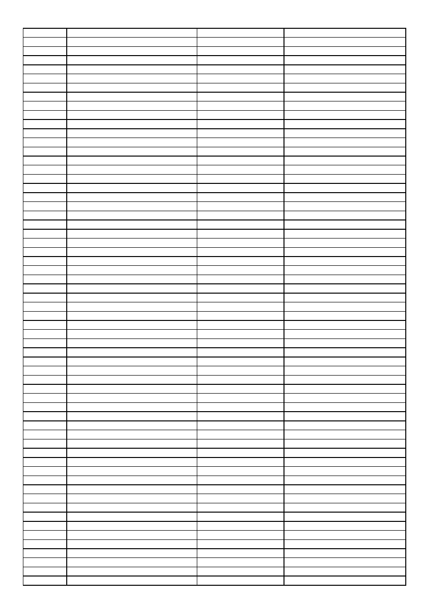
SPARE PARTS LIST
PART NO
NOTES
250111
EC 1UF 16V 11*5 R:5
C101 C125 C136 C138 C141
293108
CC-CHIP 10NF K 50V /0805 X7
C102 C104 C140
250111
C-ELA 1UF 16V 11*5 R:5
C103
251107
EC 10UF M 16V 11*5 R:5
C105 C111 C134 C142
293230
CC-CHIP 22NF K 50V /0805 X7
C108 C179
294331
CC-CHIP 330NF K 16V /0805 X
C109
291822
CC-CHIP 820PF J 50V /0805 N
C112 C131
251478
EC 47UF 16V 11*5 R:5
C113 C145
294111
CC-CHIP 100NF K 25V /0805 X
C119 C120 C121 C122
252112
EC 100UF 16V 11*6 R:5
C127
292476
CC-CHIP 4.7NF K 50V /0805 X
C128 C129 C188
250227
EC 2.2UF 16V 11*5 R:5
C130 C173 C174
252229
EC 220UF 16V 11*8 R:5
C135
250111
C-ELA 1UF 16V 11*5 R:5 LL'
SYSTEM
C143
251107
EC 10UF M 16V 11*5 R:5
C144 C170 C189
291225
CC-CHIP 220PF K 50V /0805 X
C148 C154 C156
291225
CC-CHIP 220PF K 50V /0805 X
C149 C162 C164
292110
CC-CHIP 1NF K 50V /0805 X7R
C150 C151 C152 C153 C169
291477
CC-CHIP 470PF J 50V /0805 N
C155 C157 C163 C165
292110
CC-CHIP 1NF K 50V /0805 X7R
C158 C159 C160 C161
293230
CC-CHIP 22NF K 50V /0805 X7
C166 C171 C172
294111
CC-CHIP 100NF K 25V /0805 X
C167 C168
291103
CC-CHIP 100PF J 50V /0805 N
C175 C176 C177
291560
CC-CHIP 560PF J 50V /0805 N
C178
290274
CC-CHIP 27PF J 50V NPO 0805
C180
290684
CC-CHIP 68PF J 50V /0805 NPO
LL' SYSTEM
C184
294228
CC-CHIP 220NF Z 50V /0805 Y5U
LL' SYSTEM
C185 C186
202105
C-CE 1NF K 1KV Y5P R:5
LL' SYSTEM
C187
293108
CC-CHIP 10NF K 50V /0805 X7
C191 C192 C194 C195
290684
CC-CHIP 68PF J 50V /0805 NP
C200
252112
EC 100UF 16V 11*6 R:5
C315 C338 C339
293474
CC-CHIP 47NF K 50V /0805 X7
C316
274332
C-PEM 330NF K 63V R:5
C340 C341
292223
CC-CHIP 2.2NF K 50V /0805 X
C342 C343
291223
CC-CHIP 220PF J 50V /0805 N
C346
294109
CC-CHIP 100NF K 50V /0805 X
C347 C348 C349 C350 C351
299152
CC-CHIP 1.5PF C 25V/0805
C352 C353
293108
CC-CHIP 10NF K 50V /0805 X7
C354 C355 C356
250470
EC 4.7UF 16V 11*5 R:5
C358 C359 C360 C361
294331
CC-CHIP 330NF K 16V /0805 X
CINCH
C362 C363
251478
EC 47UF 16V 11*5 R:5
C370 C371
293332
CC-CHIP 33NF K 50V /0805 X7R
C373
292110
CC-CHIP 1NF K 50V /0805 X7R
C374
294231
CC-CHIP 220NF K 16V /0805 X7R
C375
293474
CC-CHIP 47NF K 50V /0805 X7R
C376 C377 C378
292151
CC-CHIP 1.5NF K 50V /0805 X7R
C379 C380
274104
C-PEM 100NF K 63V R:5
C382 C383
253106
EC 1000UF 25V 20*13 R:5
C384
251107
EC 10UF M 16V 11*5 R:5
C386
293474
CC-CHIP 47NF K 50V /0805 X7
C401 C402 C404 C407 C420
203106
CC 10NF K 50V R:5
C405
292476
CC-CHIP 4.7NF K 50V /0805 X
C408 C409
250227
EC 2.2UF 16V 11*5 R:5
C410
290390
CC-CHIP 39PF K 50V /0805 NP
Mask type Microprocessor
C412 C413
290156
CC-CHIP 15PF K 50V /0805 NP
OTP type Microprocessor
C412 C413
290821
CC-CHIP 82PF J 50V /0805 N7
C414
292223
CC-CHIP 2.2NF K 50V /0805 X
C415
251107
EC 10UF M 16V 11*5 R:5
C416 C418 C436
290222
CC-CHIP 22PF J 50V /0805 NP
C419 C424 C431 C432
294476
CC-CHIP 470NF K 16V /0805 X
C421
DESCRIPTION
POSITION NUMBERS
SPARE PARTS LIST
179001
RC-CHIP 0R /0805 2*1.25
BG/DK SYSTEM
C423 L108 R336 R337 R338
291560
CC-CHIP 560PF J 50V /0805 N
C429 C437 C438
252229
EC 220UF 16V 11*8 R:5
C430
251478
EC 47UF 16V 11*5 R:5
C433 C439
293108
CC-CHIP 10NF K 50V /0805 X7
C435
274227
C-PEM 220NF J 50V R:5
C501
253101
EC 1000UF 35V 25*13 R:5
C503
252476
EC 470UF 25V 11*10 R:5
21"
C504
250111
EC 1UF 16V 11*5 R:5
C505 C511 C512
293152
CC-CHIP 15NF K 50V /0805 X7
C508
273333
C-PEM 33NF K 100V R:5
C508A
291477
CC-CHIP 470PF J 50V /0805 N
C509
252105
EC 100UF 50V 12*8 R:5
C510
250100
EC 1UF 160V 11*6.3 R:5
C553
271390
C-PPM 390NF J 250V R:15
C554
272820
C-PPM 8.2NF %3.5 1.5/1.6KV
21"
C555
272912
C-PPM 9.1NF %3.5 1.5/1.6KV
20"
C555
274330
C-PEM 330NF J 250V R:15
C556
251109
EC 10UF 250V 16*10 R:5
C560
202105
CC 1NF K 1KV Y5P R:5
C561
274107
C-PEM 100NF J 100V R:5
C563
252229
EC 220UF 16V 11*8 R:5
21"
C564
252482
EC 470UF 16V 12.5*10 R:5
20"
C564
271331
C-PPM 330PF J 1500V/1600V R
C565
251478
EC 47UF 16V 11*5 R:5
C571
250228
C-ELA 2.2UF 250V 11*8 R:5
C702
201476
C-CE 470PF K 1KV R:5
C705 C708 C711
274224
C-PEM 220NF K 275V-AC R22.
C901
274103
C-PEM 100NF K 275V-AC R:15
C902
202105
CC 1NF K 1KV Y5P R:5
C903 C904 C917 C918
203330
C-PPM 33NF J 630V R:15
C906
201471
CC 470PF 2KV
C907
293108
CC-CHIP 10NF K 50V /0805 X7
C909
293474
CC-CHIP 47NF K 50V /0805 X7
C910 C955 C958 C967
291123
CC-CHIP 120PF K 50V /0805 X
C911
292223
CC-CHIP 2.2NF K 50V /0805 X
C913 C914
274105
C-PEM 100NF J 250V R:10
C915
274332
C-PEM 330NF K 63V R:5
C919
202220
CC 2.2NF M 250VAC Y5U R:10
C920
202106
CC 1NF K 50V Y5P R:5
CINCH
C920 C921
202102
C-CEA 1NF K 50V R:10
CINCH
C922 C923
290561
CC-CHIP 56PF J 50V NPO 0805
CINCH
C923
273471
C-PEM 47NF K 63V R:5
HEADPHONE
C940 C941
201226
CC 220PF K 2KV Y5P R:5
C950
250470
EC 4.7UF 16V 11*5 R:5
C956
251225
EC 22UF 16V 11*5 R:5
C965
291101
CC-CHIP 100PF J 50V /1206 N
C981 C982
303993
LED LTL4221N D:3 R/D RED
D01
303991
LED IR SIR563SB3F 23/940
D02
302296
DIODE 1N4148 26MM
D103
302289
DIODE 1N4148 52MM
D103
303195
DIODE 4148 MELF
D107
303223
DIODE-CHIP BA682 SOD80
LL' SYSTEM
D180 D181
303988
LED LTL 4224 RED (SHORT LEG
21"
D418
303850
LED LTL 4263 RED L=25.4
20"
D418
303308
DIODE RF2007
D502
302296
DIODE 1N4148 26MM
D503 D559
300305
DIODE BA157
D552 D556
303217
DIODE RGP10J
D553 D560
303195
DIODE 4148 MELF
D557
SPARE PARTS LIST
302289
DIODE 1N4148 52MM
D558
302948
DIODE 1N4007
D701
302289
DIODE 1N4148 52MM
D702 D703 D704
303308
DIODE RF2007
D901 D902 D903 D904
303217
DIODE RGP10J
D905
302289
DIODE 1N4148 52MM
D906 D907 D908 D909
303217
DIODE RGP10J
D950
303281
DIODE RGP50D
D951
056721
SER.FILTER TPS5.5MWA
BG SYSTEM
F101
056762
SER.FILTER TPT02B
BG/DK SYSTEM
F101
056745
SER.FILTRE TPS6.0MB
I SYSTEM
F101
056731
SER.FILTRE TPSRD5M50W00-A0
LL' SYSTEM
F101
056640-01
SER.FILTRE MKT40.4MA110P-TF01 MURATA LL' SYSTEM
F102
056641
SER.FILTRE MKT40.9MA110P MURATA
I SYSTEM
F401
452382
IC-CHIP S3C1840DA9/SMB1
IC01
452842-01
IC STV2246C
PAL BG, I SYSTEMS
IC101
452836-01
IC STV2248C
PAL + SECAM LL' SYSTEM
IC101
452990
IC STV2249C
PAL/SEC BG/DK SYSTEM
IC101
452985
IC-CHIP MC14053BD SOIC16
TWO SCARTS
IC102
452374
IC L78L05 ACZ TR
IC315 IC953
452575-02
IC MSP3400G PP B8 V3
NON NICAM
IC316
452800
IC MSP3410G PSDIP64 AUDIO P
NICAM
IC316
452700
IC TDA 8944J
IC317
452844
IC-CHIP ST24C08 (EEPROM) 5V
IC401
MB5641-A11
IC ST92195C7 / 64K A-OSD MASK (EMJ)
IC402
MB5641-B11
IC ST92195C7 / 64K B-OSD MASK
IC402
452648
IC TDA8174AW
IC501
452986
IC TDA16847
IC901
451518
IC KA317TU T0220CASE
IC951
452374
IC L78L05 ACZ TR
IC953
053711
COIL 10UH K (TAIYO) LAL03
L101
L102 L315 L316
053805
COIL-CHIP 1UH K /0805
L103
L106
053740
COIL 1UH K LAL03
L104
053750
COIL 5.6UH K
DK SYSTEM
L105
053806
COIL-CHIP 8.2UH K /0805
BG SYSTEM
L107
179001
RC-CHIP 0R /0805 2*1.25
LL' SYSTEM
L107
053816
COIL 18UH K /3.4 26MM
L401
L402
053726
COIL-CHIP 22UH %20/0805
L403
053798
COIL-CHIP 18UH K /0805
L404
053715
COIL 6.8UH K R12.5
L502
051585
COIL H-LIN 70UH
L551
051815
LINE FILTER 2 X 18 MH MIN.TYPE
L901
053739
COIL CHOKE 50UH
L950
053506-01
COIL DEMOD 38.9 HEX
LC100
055597
FERRITE BEAD 12*8
056210
CER.RESONATOR GSB455E
Q01
132500
R-VAR 5K (V) 5*3
P901
056023
CRYSTAL 4.433619MHZ
Q101
056660
CRYSTAL 3.579545 90OHM
Q102
056952
CRYSTAL 18.432MHZ +-30PPM
Q315
056013
CRYSTAL 4 MHZ
Q401
179002
RC-CHIP 0R /1206
R01
173273
CFR-CHIP 27K J 1/10W /0805
R101 R427
171150
RC-CHIP 150R J 1/10W /0805
R102 R124 R333 R334
171221
RC-CHIP 220R J 1/10W /0805
R104 R129 R441 R442
172101
RC-CHIP 1K J 1/10W /0805
R105 R112 R117 R120 R144
SPARE PARTS LIST
170472
RC-CHIP 47R J 1/10W /0805
R107 R106 R108 R113
101470
CFR 470R J 1/4W /6 52MM
R109 R110 R111
171471
RC-CHIP 470R J 1/10W /0805
R116
171102
RC-CHIP 100R J 1/10W /0805
R118 R119 R160
102141
CFR 1K J 1/4W /6 26MM
R121
172823
RC-CHIP 8.2K J 1/10W /0805
R122
172561
RC-CHIP 5.6K J 1/10W /0805
R123 R415 R416
171182
RC-CHIP 180R J 1/10W /0805
R125 R126
172101
RC-CHIP 1K J 1/10W /0805
R127 R172 R173
173101
RC-CHIP 10K J 1/10W /0805
R128
173562
RC-CHIP 56K J 1/10W /0805
R130
174331
RC-CHIP 330K J 1/10W /0805
R131 R188
172225
RC-CHIP 2.2K J 1/10W /0805
R132
171270
RC-CHIP 270R J 1/10W /0805
R135 R136 R137
173479
RC-CHIP 47K J 1/10W /0805
R138
172335
RC-CIHP 3.3K J 1/10W /0805
R139
171221
RC-CHIP 220R J 1/10W /0805 LL'
SYSTEM
R142
170750
RC-CHIP 75R J 1/10W /0805
R152 R154 R163 R164 R166
170683
RC-CHIP 68R J 1/10W /0805
R157
170750
RC-CHIP 75R J 1/10W /0805
R158 R174
171332
RC-CHIP 330R J 1/10W /0805
R159 R161 R168 R208
171102
RC-CHIP 100R J 1/10W /0805
R160 R162 R182 R183 R184 R189
172101
RC-CHIP 1K J 1/10W /0805
R165 R167
171102
RC-CHIP 100R J 1/10W /0805
R169 R171 R121
172475
RC-CHIP 4.7K J 1/10W /0805
R175 R176
173479
RC-CHIP 47K J 1/10W /0805
R177 R178 R179 R180
101117
RC 100R J 1/4W 26MM
LL' SYSTEM
R185
173101
RC-CHIP 10K J 1/10W /0805 LL'
SYSTEM
R186
R191
102338
RC 3.3K J 1/4W /6 52MM
LL' SYSTEM
R190 R192
172225
RC-CHIP 2.2K J 1/10W /0805 LL'
SYSTEM
R193
101106
RC 100R J 1/4W 52MM
LL' SYSTEM
R194
179002
RC-CHIP 0R /1206
LL' SYSTEM
R195
179001
RC-CHIP 0R /0805 2*1.25
R203 R209 L109 R181
171332
RC-CHIP 330R J 1/10W /0805
HEADPHONE
R315 R316
172335
RC-CIHP 3.3K J 1/10W /0805
R317 R318 R320
171102
RC-CHIP 100R J 1/10W /0805
R321 R322
171471
RC-CHIP 470R J 1/10W /0805
CINCH
R328 R345
173123
RC-CHIP 12K J 1/10W /0805
R329 R330
291103
CC-CHIP 100PF J 50V /0805 N
R335
102685
CFR 6.8K J 1/4W /6 52MM
R354 R355
109474
CFR 4.7R J 1/2W /9 26MM
R358 R359
173101
RC-CHIP 10K J 1/10W /0805
R401 R404 R426 R428
172475
RC-CHIP 4.7K J 1/10W /0805
R402 R406 R407 R408 R434 R440
172225
RC-CHIP 2.2K J 1/10W /0805
R403
172273
RC-CHIP 2.7K J 1/10W /0805
R405 R511
172101
RC-CHIP 1K J 1/10W /0805
R409 R520
171471
RC-CHIP 470R J 1/10W /0805
R410 R411
171332
RC-CHIP 330R J 1/10W /0805
R417
171685
RC-CHIP 680R J 1/10W 0805
R425 R564
172823
RC-CHIP 8.2K J 1/10W /0805
R435 R438
173393
RC-CHIP 39K J 1/10W /0805
R437 R904
129236
RW 2.2R J 0.75W 73MM
R501
101471
CFR 470R J 1/2W /9 52MM
R502 R557
100220
CFR 22R J 1/2W 52MM
R503
174151
RC-CHIP 150K J 1/10W /0805
R505 R506
172183
RC-CHIP 1.8K J 1/10W /0805
R508 R512
119125
RM 1.2R J 1/2W 52MM
21"
R509
119153
RM 1.5R J 1/2W 52MM
20"
R509
170472
RC-CHIP 47R J 1/10W /0805
21"
R510
173101
RC-CHIP 10K J 1/10W /0805
R513 R423
102141
CFR 1K J 1/4W /6 26MM
R519
SPARE PARTS LIST
174104
RC-CHIP 100K J 1/10W /0805
R521
172823
RC-CHIP 8.2K J 1/10W /0805
R522
172225
RC-CHIP 2.2K J 1/10W /0805
R523
172394
RC-CHIP 3.9K J 1/10W /0805
R524
103224
CFR 22K J 1/4W 52MM
R526
110823
RMO 82R J 3W R:20
R554
100473
CFR 47R J 1/4W /6 52MM
R555 R921
113114
RM 10K J 1/2W 52MM
R558
119337
RMO 3.3R J 2W R:27.5 TAPE
R559
119478
RMF 0.47R J 1W
20"
R560
119109
RNF 0.1R J 0.4W (UFLB) 52MM
21"
R560
103136
CFR 10K J 1/4W /6 26MM
R562
172683
RC-CHIP 6.8K J 1/10W /0805
21"
R563
172823
RC-CHIP 8.2K J 1/10W /0805
20"
R563
101681
CFR 680R J 1/2W /9 52MM
R568
103475
CFR 47K J 1/4W /6 52MM
R705
102159
CFR 1.5K J 1/2W /9 52MM
R711 R713 R715 R716
101683
CFR 680R J 1/4W /6 52MM
R901
154216
NTC 5.1R M (S234R)
R901
154234
PTC 9R/3 PIN
R902
113683
RMO 68K J 1.5W 73MM
R903
173101
RC-CHIP 10K J 1/10W /0805
R905
114826
RM 820K %1 1/2W 52MM
R907 R908
172335
RC-CIHP 3.3K J 1/10W /0805
R909
114562
RM 560K %1 1/2W 52MM
R911 R922
174223
RC-CHIP 220K J 1/10W /0805
R912
115225
RMO 2.2M J 1/2W
R913
171822
CFR-CHIP 820R J 1/10W /0805
R914
173221
RC-CHIP 22K J 1/10W /0805
R915
172683
RC-CHIP 6.8K J 1/10W /0805
R917
173333
RC-CHIP 33K J 1/10W /0805
R918
115470
RM 4.7M J 1/2W 52MM
R920
113393
RM 39K J .5W 52MM
R950
171240
RC-CHIP 240R %1 1/10W /0805
R953
112131
RM 1.3K %1 1/4W 26MM
R954
109560
CFR 5.6R J 1/4W /3.2 52MM
R956
101106
CFR 100R J 1/4W 52MM
R957
120234
RMF 22R J 1/2W
R958
129109
RWF 0.1R J 0.75W 73MM
R959
119109
RNF 0.1R J 0.4W (UFLB) 52MM
R960
452521
IR RECEIVER TSOP 1838
S401
054261
FUSE 2.5AT (215 SER.)
S901
056749
SAW FILTER OFW G1985M
BG SYSTEM
SAW1
056070
SAW FILTER OFW K2966M
BG/DK SYSTEM
SAW1
056114
SAW FILTRE OFW J1980M I SISTEM
I SYSTEM
SAW1
056709
SAW FILTRE OFW K3953M
LL' SYSTEM
SAW1
056767
SAW FILTRE OFW K9456M
LL' SYSTEM
SAW2
031251
SCART SOCKET 14.1
SK101
031197
SCART SOKET HR-DM2441S-O
SK102
401047
TRN BC337-25
T01
401142
TRN-CHIP BC858B SOT23
T02
7KY136-PS1
TUNER ENV57D60G3 ASIMETRIK
T100
401141
TRN-CHIP BC848B SOT23
T101
T102 T103
401141
TRN-CHIP BC848B SOT23
LL' SYSTEM
T105 T108
400989
TRN BC558B
HEADPHONE
T315
T316
401142
TRN-CHIP BC858B SOT23
T317
T318 T319 T320
401141
TRN-CHIP BC848B SOT23
T321
T322
401142
TRN-CHIP BC858B SOT23
T401
401141
TRN-CHIP BC848B SOT23
T406
T501 T502 T402
SPARE PARTS LIST
401334
TRN STX112
T551
401332
TRN BU808DFI
T552
401397
TRN 2SC 2482
T701
T703 T705
401366
TRN BF421
T702
T704 T706
401424
TRN STP4NK60ZFP
T901
400901
TRN BC327-25
T902
401141
TRN-CHIP BC848B SOT23
T906
058013-EL6
FBT 20/21"
TR552
059038-EL1
SMPS 2021/SLOT TR/... 16.1
TR901
031882
CONN.HOUSING X2010 GREY
SINGLE SCART
X102
031730
CONN.HOUSING 2012 GREY
TWO SCARTS
X102
031730
CONN.HOUSING 2012 GREY
X103
031856
CONN.HOUSING X2003 BLACK
X104
031283
PIN HEADETR 2.54MM 9*1 YATIK
X315
031854
CONN.HOUSING X2003 GREY
X316
031323
CON.MKF19400-6-0-1010
SINGLE SCART
X317
031284
PIN HEADETR 2.54MM 12*1 YATIK
TWO SCARTS
X317
031857
CONN.HOUSING X2003 RED
X318
031860
CONN.HOUSING X2004 BLACK
X319
031858
CONN.HOUSING X2004 GREY
X320
031850
CONN.HOUSING 2'LI GREY
X501
031777
CON.HOUSING LOCKED 5/4
X551
A99553-AS
CABLE WITH HOLDER 3+1P L=380
X552
031530-02
INCHANG/CRT SOCKET ISHM23S-W
X703
31675
CON.HOUSING 2P MALE
X901
31672
CON.HOUSING 2P MALE RED
X902
7KY537-AS
CABLE HARNESS 3+3P L=380 HP.MOD.
X920
31165
KONN. CINCH ........ YELLOW HOR.14
X921
31164
KONN. CINCH ........... RED HOR.14.1
X922
31163
KONN. CINCH ........ WHITE HOR.14.1
X923
31795
KONN.S-VHS
X924
7XY517-AS
CABLE HARNESS 3P L=360 HP.MOD.
X940
302297
DIODE Z. 3.9V 26MM
ZD406
303771
DIODE Z. UZT33V
ZD570
302298
DIODE Z. ZPD5.1V 26MM
ZD901
303735
MTZJ5.6B
ZD952
056520-SB1
CPT SEB A48ECR43X51
056521-SB1
CPT SEB A51EER33X41
620167-AS
DEGAUSSING COIL ASSY 20" BA
621167-AS
DEGAUSSING COIL ASSY 21" BA
5T1187F
RC BEKO TYPE SILV.14.1
7TV187
RC A TYPE FUME 14.1
6VM187
RC A TYPE SILVER 14.1
7TK187
RC B TYPE FUME 14.1
7GA107-AS
SPEAKER 8R.../7W(M) 50X90
528107-AS
SPK.FOST.8R/7W PRJ-C POWER-
7ZY107-AS
SPK.FT 8R/7W(NOM)(120X50MM)
Please note that Product Part List Files should be investigated for the mechanical parts like cabinets, etc.
Wyszukiwarka
Podobne podstrony:
Service Manual Bmw k100Rs 16 Valve
hplj 5p 6p service manual vhnlwmi5rxab6ao6bivsrdhllvztpnnomgxi2ma vhnlwmi5rxab6ao6bivsrdhllvztpnnomg
Oberheim Prommer Service Manual
Korg SQ 10 Service Manual
MAC1500 service manual
Kyocera Universal Feeder UF 1 Service Manual
Proview RA783 LCD Service Manual
indesit witp82euy Service Manual
Glow Worm installation and service manual Hideaway 70CF UIS
Proview PZ456 LCD Service Manual
Glow Worm installation and service manual Ultimate 50CF UIS
ewm2000 service manual
Glow Worm installation and service manual Ultimate 60CF UIS
Proview SH770I LCD Service Manual
M23 Service Manual
Glow Worm installation and service manual Glow micron 60
Konica Minolta QMS 7115, 7118 Service Manual
Honda NSR125 '87 Service Manual
więcej podobnych podstron