
Table of Contents
Subject
Page
Purpose of the System. . . . . . . . . . . . . . . . . . . . . . . . . . . . . . . . . . . . . . . 9
Functions . . . . . . . . . . . . . . . . . . . . . . . . . . . . . . . . . . . . . . . . . . . . . . . 10
System Components . . . . . . . . . . . . . . . . . . . . . . . . . . . . . . . . . . . . . . . 11
Electro-mechanical Actuating Unit. . . . . . . . . . . . . . . . . . . . . . . . . . . . . . 12
Emergency Release . . . . . . . . . . . . . . . . . . . . . . . . . . . . . . . . . . . . . . . . 14
Principle of Operation . . . . . . . . . . . . . . . . . . . . . . . . . . . . . . . . . . . . . . . 16
Safety Concept . . . . . . . . . . . . . . . . . . . . . . . . . . . . . . . . . . . . . . . . . . . 22
EMF Self Diagnostics . . . . . . . . . . . . . . . . . . . . . . . . . . . . . . . . . . . . . . . 25
Workshop Hints . . . . . . . . . . . . . . . . . . . . . . . . . . . . . . . . . . . . . . . . . . . 26
Check Control and Control Display Fault Descriptions . . . . . . . . . . . . . . . 28

BRAKES
Model: E65 - 745i
Production Date: 11/2001
Objectives of The Module
After Completing this module, you will be able to:
• Explain the 2-Stage Brake Pad Wear Sensor.
• Demonstrate parking brake operation including “Auto Hold” activation.
• List and perform the procedure to resume operation after an emergency release.
2
E65 Brakes
Parking Brake (EMF)
Purpose of The System
The Electro-mechanical Parking Brake (EMF) is used for the first time in series production.
The EMF is used to secure a stationary vehicle, preventing it from rolling away by firmly
locking the parking brake. The EMF is an automatic comfort oriented system that replaces
the previous handbrake or foot operated parking brake. The driver can apply and release
the parking brake by pressing a push button.
The system is designed for the characteristic
requirements of the E65:
• Consideration for safety
• Optimum functionality
• Maximum system usage
• Best comfort and convenience
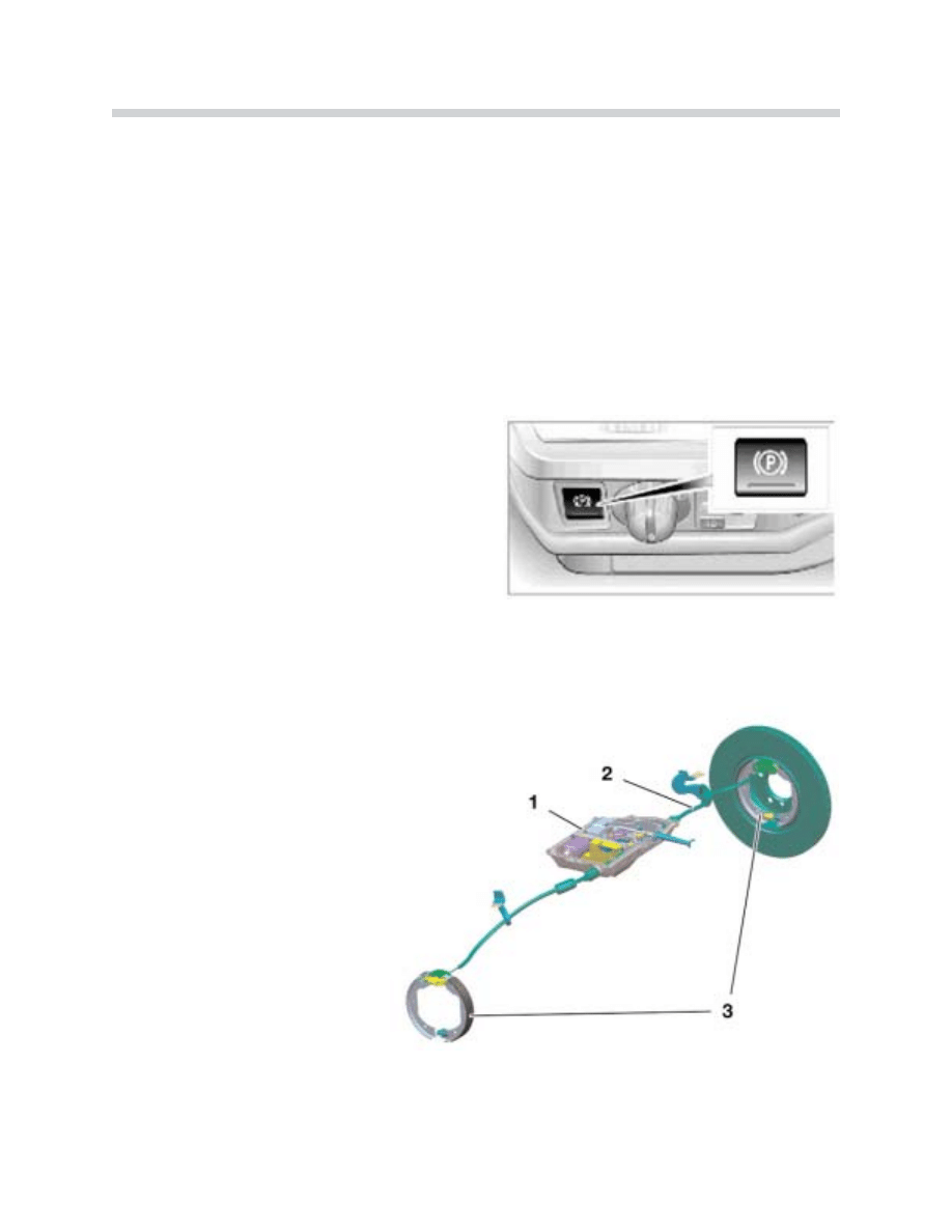
The Parking Brake push button is located in the
instrument panel to the left of the headlight
switch. The push button is an integral compo-
nent of the Light Module.
The EMF mechanically locks the
parking brake when the vehicle is
stationary and provides an inde-
pendent brake system as
required by law (in addition to the
service brakes).
The EMF system offers addition-
al comfort and safety functions.
9
E65 Brakes
42-06-06
42-06-08
EMF System
1. EMF actuator
2. Bowden cable
3. Drum brakes (integral in the rear
brake discs)

10
E65 Brakes
Basic Functions: There are two different parking brake functions depending on the oper-
ating status of the vehicle.
L
Lo
oc
ck
kiin
ng
g ((B
Brra
ak
ke
e A
Ap
pp
plliie
ed
d))::
• With the engine running or the vehicle rolling, the parking brake function acts on the
front and rear axle by the DSC hydraulically applying the service brakes.
• When the engine is not running and the vehicle is stationary, the electro-mechanical
parking brake is applied.
D
Dy
yn
na
am
miic
c B
Brra
ak
kiin
ng
g::
• Braking required to decelerate a moving vehicle is identified by the DSC system when
the parking brake push button is pressed while driving. The braking procedure is regu-
lated by the DSC hydraulically applying the service brakes and takes place for as long
as the push button is pressed.
Automatic Hold: This comfort function is selected using the controller or with the free pro-
grammable button on the multifunction steering wheel. After braking to a standstill, the
vehicle is held by the DSC hydraulically applying the service brakes. The brakes are
released by pressing the accelerator pedal. The hold and release function prevents “creep-
ing” in stop and go traffic and “roll back” before pulling away on an incline (Hill Hold).
Brake Pedal “Feel”: The response of the brake pedal may change slightly (accompanied
by an activation sound) because the parking brake function is activated using the brake
system’s hydraulic circuits - this is normal.
Emergency Release: A mechanical emergency release is provided to release the parking
brake in the event of an actuating unit failure or a dead battery. It is possible to release the
mechanical actuating parking brake unit using the emergency release tool and an open end
wrench found in the vehicle tool kit.
N
No
otte
e:: In addition, refer to the automatic transmission section for the emergency mechani-
cal parking lock release procedure.
Special Function: During vehicle operation, brake lining “seating” is conducted at defined
intervals to ensure and maintain the effectiveness of the parking brake. The brake lining
seating is performed to remove corrosion from the parking brake shoes and brake drums.
The procedure automatically takes place approximately every 1000 km or once a month
and is transparent to the driver.
System Components
11
E65 Brakes
42-06-09
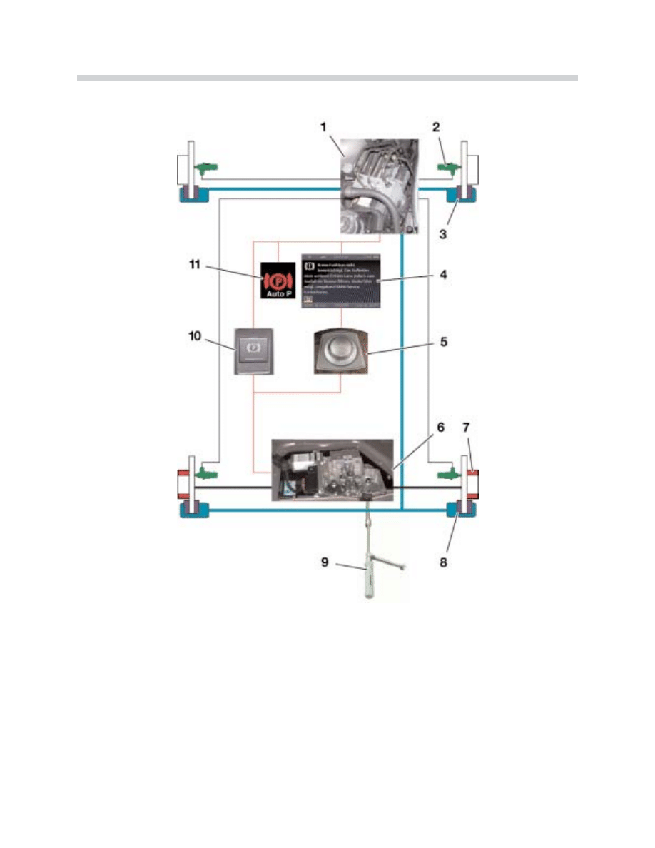
EMF Parking Brake
1. DSC module
7. Parking brake
2. Wheel speed sensors
8. Service brake, rear axle
3. Service brake, front axle
9. Mechanical emergency release tools
4. Control display
10. Parking brake push button
5. Controller
11. Display in instrument cluster
6. EMF actuating unit
Electro-mechanical Actuating Unit (EMF): The EMF receives the parking brake request
and activates an electric actuator (motor) to tension the parking brake cables. The EMF
actuating unit is located under the luggage compartment floor in front of the spare wheel
recess.
End Stop: The end stop is the
“zero point” for the initial position
which is required for the parking
brake cable installation (release -
no tension).
The balance arm rests against
the end stop the first time the
brake is released when the igni-
tion is on (KL15).
Hall sensors are mounted on the
motor to detect the speed and
position. The control module
detects the end stop by the
increase in actuator motor cur-
rent and the decrease in the
motor speed (Hall sensors).
12
E65 Brakes
42-06-04
42-06-10
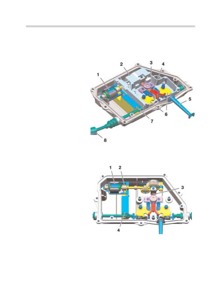
Electro-mechanical Actuating Unit
1. Actuator (motor with 2 Hall sensors)
2. Gear mechanism
3. Balance arm
4. End stop
5. Guide tube for emergency operation
(release)
6. Cable module
7. Control module
8. Bowden cable (one of two)
EMF Actuation
1. Electric motor
2. Hall sensors
3. Spindle (worm)
4. Control module
When activated, the spindle is turned by the motor using a gear drive mechanism to apply
the parking brakes. The balance arm is pulled by the spindle (worm) and will compensate
for the slight difference in side to side cable length. The balance arm is linked by connect-
ing levers to pull the cable pulleys inwards towards the direction of the spindle rotation. The
cables are attached to the cable pulleys which are pulled “in” to apply the parking brakes.
Once the hold position is reached, the spindle worm gear ensures cable tension and will
not release with out spindle rotation.
Gear Drive Mechanism with Coil Spring: This is designed as a three stage (reduction)
gear mechanism consisting of a worm, spur gear and spindle. The holding force for the
parking brake is assisted by a coil spring mounted on the end of the spindle.
13
E65 Brakes
42-06-12
42-06-13
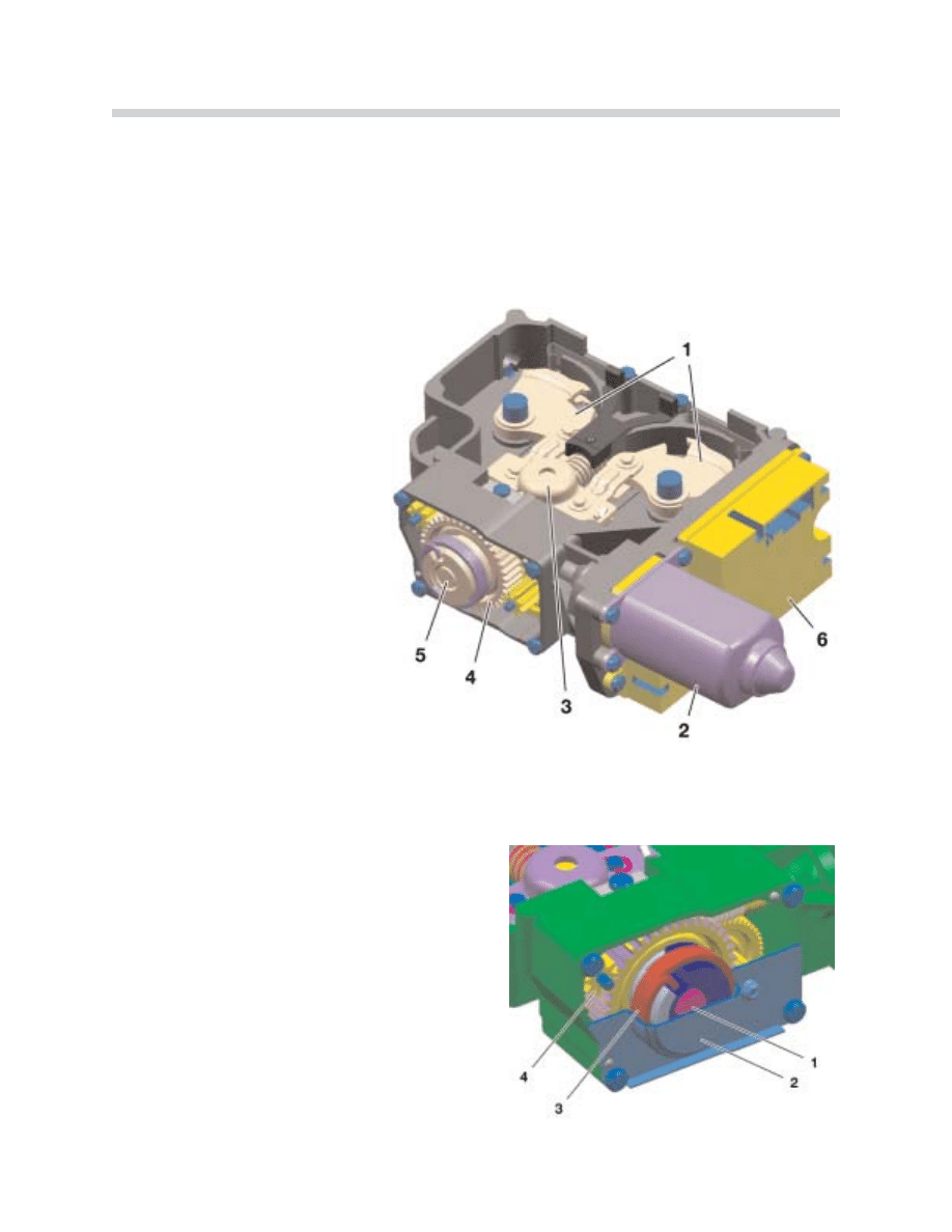
Cable Operation
1. Cable pulley
2. Actuator motor
3. Balance arm
4. Gear drive mechanism
5. Spindle
6. Control module
Gear Drive Mechanism
1. Spindle
2. Coil spring cover
3. Coil spring
4. Emergency release drive gear
When the brake is released, the spindle is turned by the motor and gear drive mechanism
in the opposite direction. The balance arm, connecting levers and cable pulleys are pushed
outwards by the spindle (worm). The cables are also pushed “out” to release the parking
brakes. To assist in the release, return springs are installed in the parking brake assemblies
inside the brake discs.
N
No
otte
e:: With the manual emergency release, the spindle can be turned through the gear drive
mechanism with the tools found in the vehicle tool kit to release the parking brake.
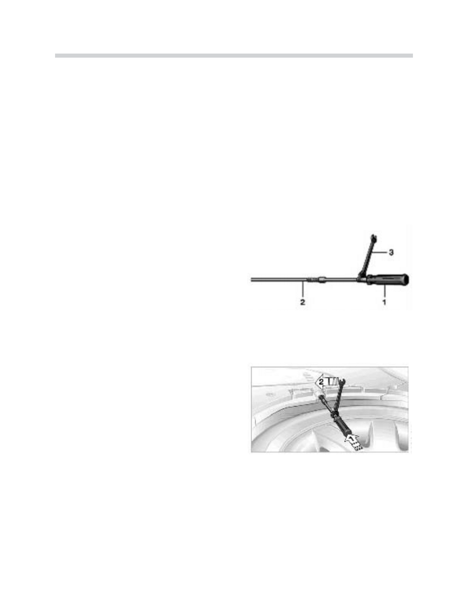
Workshop Hints
Emergency Release: The parking brake is manually released directly through the gear
drive mechanism.
The tools in the vehicle tool kit to release the
parking brake are:
C
Ca
au
uttiio
on
n:: M
Ma
ak
ke
e s
su
urre
e tth
he
e ttrra
an
ns
sm
miis
ss
siio
on
n iis
s iin
n tth
he
e
P
Pa
arrk
k p
po
os
siittiio
on
n b
be
effo
orre
e rre
elle
ea
as
siin
ng
g tth
he
e p
pa
arrk
kiin
ng
g
b
brra
ak
ke
e!!
To release the brake, the extension rod is insert-
ed through a guide tube located in the luggage
compartment floor in front of the spare wheel
recess (1). Maintain pressure on the tool.
Using the open end wrench and the screwdriv-
er handle, turn the release tool in a counter-
clockwise direction (2). The cable tension
release will be felt during this procedure.
N
No
otte
e:: After a power failure/interruption, it is possible that the vehicle can not be moved after
releasing the parking brake using the emergency release. The parking lock of the automatic
transmission can still be engaged. Refer to the automatic transmission section for the
emergency mechanical parking lock release procedure. T
Th
he
e p
pa
arrk
kiin
ng
g b
brra
ak
ke
e m
ma
ay
y o
on
nlly
y b
be
e
u
us
se
ed
d a
ag
ga
aiin
n iiff iitt iis
s rre
elle
ea
as
se
ed
d m
ma
an
nu
ua
alllly
y a
afftte
err a
a p
po
ow
we
err iin
ntte
errrru
up
pttiio
on
n.. IIff tth
hiis
s iis
s n
no
ott p
pe
errffo
orrm
me
ed
d,, tth
he
e
tth
he
e p
pa
arrk
kiin
ng
g b
brra
ak
ke
e m
ma
ay
y ffa
aiill tto
o o
op
pe
erra
atte
e c
co
orrrre
ec
cttlly
y!!
14
E65 Brakes
Emergency Release
1. Screwdriver handle
2. Emergency-release tool (spring loaded)
3. 10 mm open-end wrench
42-06-09
42-06-10
Resuming Operation after Emergency Release: When the voltage supply has been
restored after the emergency release, the parking brake p
pu
us
sh
h b
bu
utttto
on
n m
mu
us
stt b
be
e p
prre
es
ss
se
ed
d 3
3
ttiim
me
es
s a
att iin
ntte
errv
va
alls
s o
off a
ap
pp
prro
ox
x.. 5
5 s
se
ec
co
on
nd
ds
s tto
o iin
niittiia
alliizze
e tth
he
e s
sy
ys
stte
em
m.. This procedure is also
described in the Owner's Handbook and Towing Instructions for BMW 7 Series.
• 1
1s
stt p
prre
es
ss
s - The control module attempts to release the brake. Since the brake has been
released mechanically by the emergency release, the motor cannot run back and blocks.
The control module recognizes a disengaged setting.
• 2
2n
nd
d p
prre
es
ss
s - The motor will move forward applying the parking brake. The control mod-
ule detects an engaged setting. The “P” indicator light illuminates in red.
• 3
3rrd
d p
prre
es
ss
s - The motor will run backward releasing the parking brake and the “P” indica-
tor light goes out. The parking brake is ready for operation.
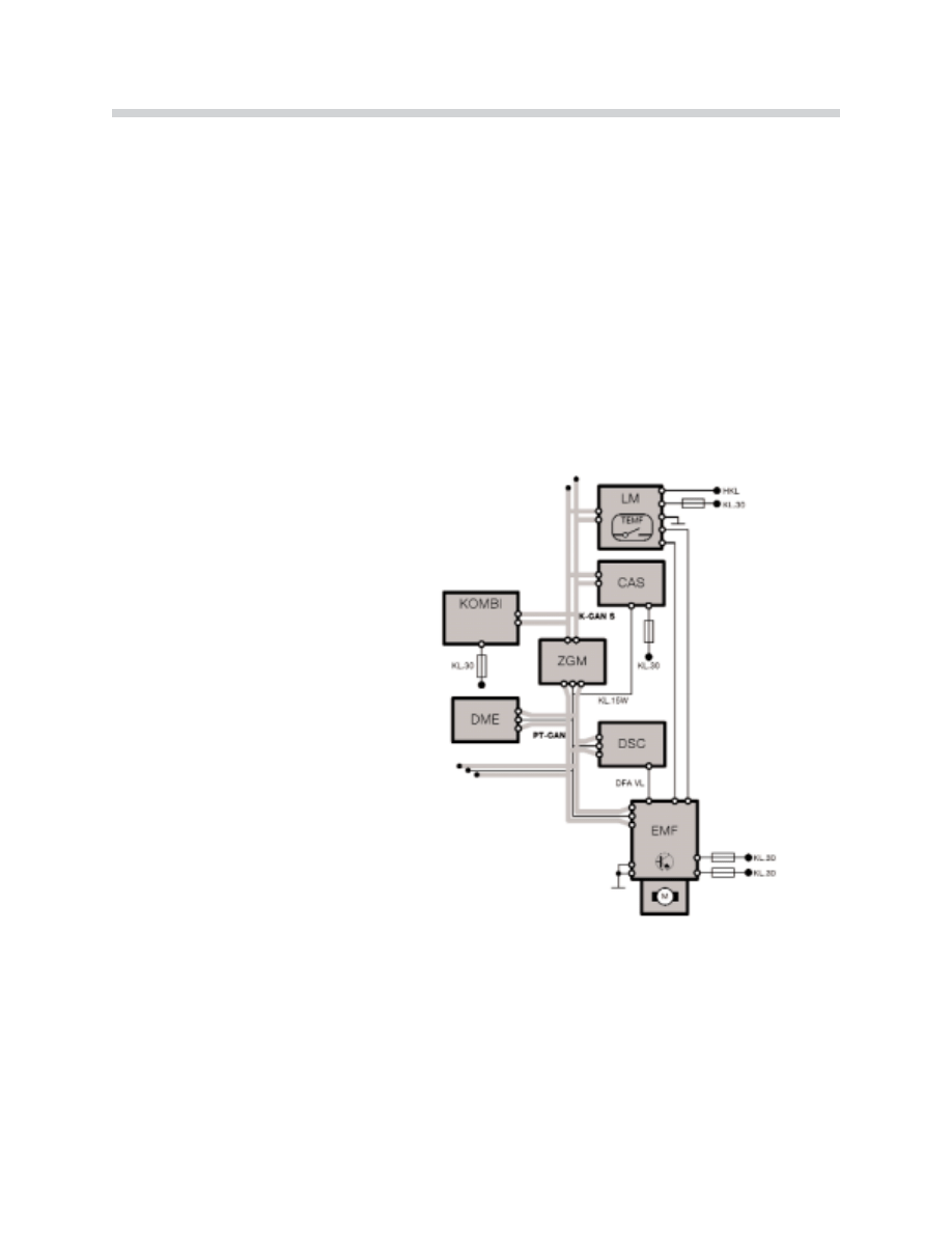
Control Module: The parking
brake control module (integral in
the EMF) is linked to other control
modules for communication by
the PT-CAN and K-CAN Busses.
Diagnostic communication is pro-
vide through the ZGM over the PT-
CAN Bus.
When the parking brake push button is pressed with the engine running, a fixed brake pres-
sure is built up by the DSC hydraulic unit and applied to the service brakes.
The force applied at the spindle is calculated in the parking brake control module. The con-
trol module first determines the current flow of the actuating motor accounting for the tem-
perature of the motor coil (affecting resistance). Hall sensors are mounted on the motor to
detect the speed and position. The actuating force is calculated by evaluating the speed
reduction of the motor (speed is a function of torque).
15
E65 Brakes
42-06-15
LM Light module
DSC Dynamic stability control
TEMF Parking brake push button
CAS Car access system
ZGM Central gateway module
DFA VL speed signal (seperate
hard wire backup), left front wheel
Hard Wire
Switch Input
Principle of Operation
Parking Brake Control
Two separate controls are provided to operate the parking brake functions.
1
1.. T
Th
he
e P
Pu
us
sh
h B
Bu
utttto
on
n,, located in the instrument panel to the left
of the steering wheel is used for the basic function. This
will apply and release the parking brake when the vehicle
is stationary and provide "Dynamic Braking" when the vehi-
cle is driven depending on the vehicle speed.
When the vehicle is stationary, it functions as an ON/OFF
(momentary) push button. Only in the Dynamic Braking
mode, the brake is applied for as long as the button is
pressed.
2
2.. T
Th
he
e a
ac
cttiio
on
n ffiie
elld
d iin
n tth
he
e m
me
en
nu
u o
off tth
he
e c
co
on
nttrro
oll d
diis
sp
plla
ay
y provides a second control. The menu
screen is activated and controlled by the driver to activate or deactivate the "Automatic
Hold" parking brake function.
This function can also be activated and de-
activated with the free programmable but-
ton on the multifunction steering wheel (if set
in the Control Display).
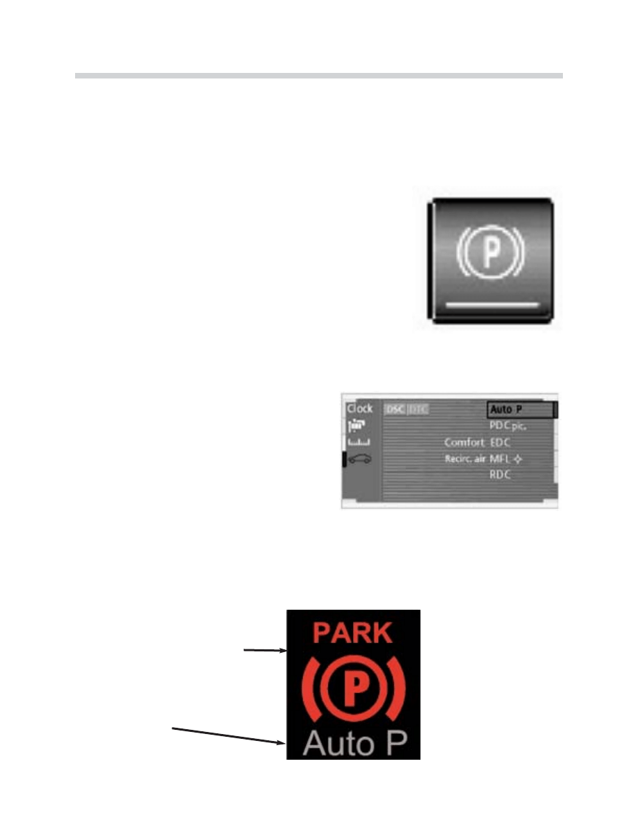
Indicator Lights
The driver is informed of the parking brake system status by an indicator light in the instru-
ment cluster. When a fault is present, an additional message in the Control Display will pro-
vide more information. The parking brake control module communicates via the PT-CAN
and K-CAN Busses. The light is activated as part of the pre-drive check when the ignition
is switched on.
Parking brake indicator lamp
Function lamp
16
E65 Brakes
42-06-08
42-06-17
42-06-07

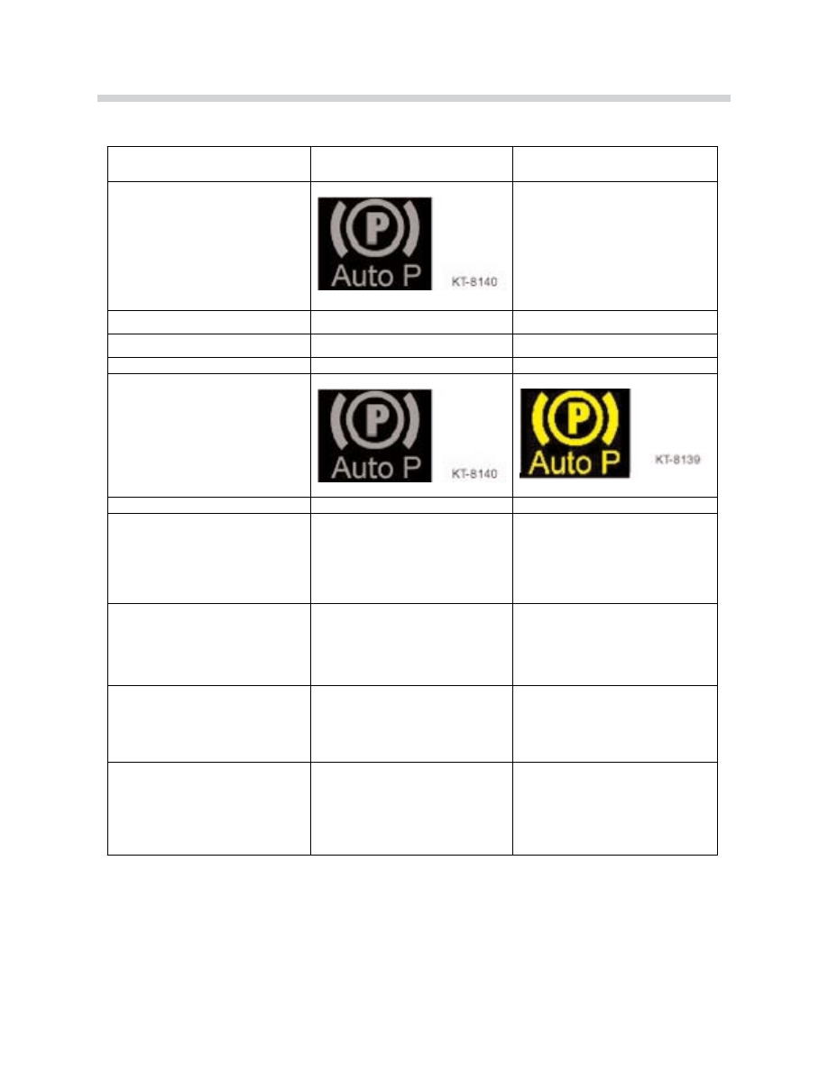
Indication
In the basic function, application of the parking brake is indicated by a red LED in the brake
symbol and by the letter P on the inside. The letters "PARK" are illuminated in the indicator
light for as long as the parking brake is applied.
The P symbol indicates that the requested status of "release" or "apply" is reached. When
the parking brake is operated while driving (Dynamic Braking), an acoustic warning signal
is additionally activated (multiple gong).
Automatic Hold Indication
Standby of the automatic hold function is indicated by the green lettering "AUTO-P" inte-
grated in the light. The parking brake signal is additionally indicated when the automatic
hold function is active and the vehicle is stopped. The parking brake symbol lights up in
green because the hold function is activated by the DSC with all 4 wheel (service) brakes.
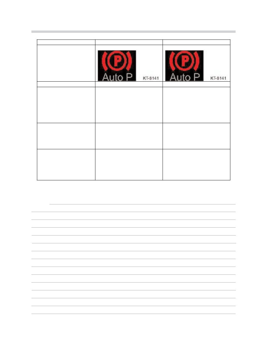
After the brake has been released when starting off (automatically), the green parking brake
symbol goes out and only the green standby indication "AUTO-P" remains active. The tran-
sition from hydraulic to mechanical mode takes place automatically when the engine is
switched off. The light changes from green to red indicating the parking brake is applied
and the DSC (service brakes) are released.
Additional Indication
The driver is alerted of parking brake malfunctions by a yellow indicator light in the instru-
ment cluster. In addition, the same symbol is illuminated in the variable indicator warning
field and briefly explained by a text note.
In addition to the parking brake status, the variable indicator light is also made available to
other control modules. It is only used by the parking brake control module for specific
faults.
When the variable indicator light appears, the fault is explained in the Check Control dis-
play accompanied by additional information in the Control Display (Condition Based
Service).
17
E65 Brakes
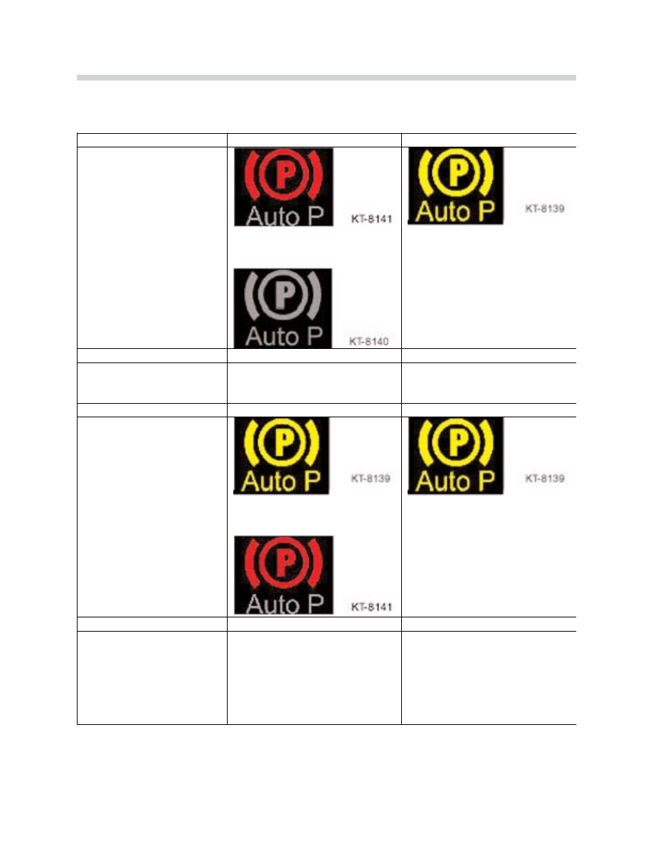
IIn
nd
diic
ca
attiio
on
n E
Ex
xa
am
mp
plle
es
s::
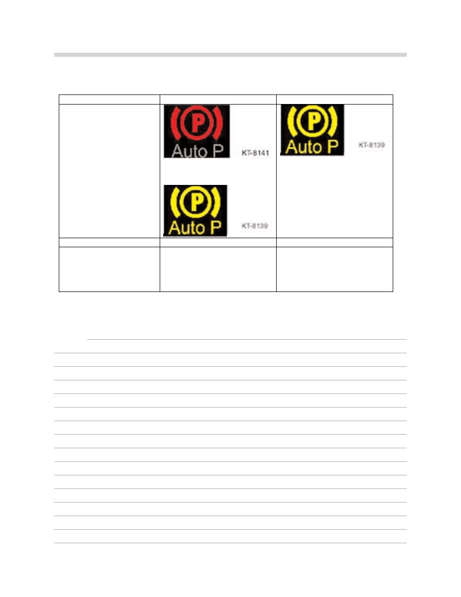
18
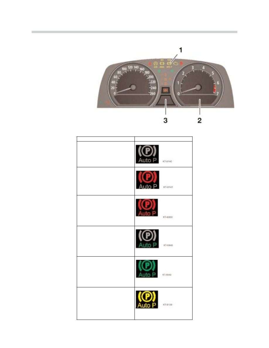
E65 Brakes
S
Syys
stte
em
m ffu
un
nc
cttiio
on
n
IIn
nd
diic
ca
atto
orr lla
am
mp
ps
s
Parking brake released
Parking brake applied
Dynamic braking
+
Acoustic signal (gong)
Automatic hold standby
Automatic hold active
System error
Instrument Cluster
1. Parking brake indicator light
2. Check Control display
3. Variable indicator warning field

Basic Parking Brake Function with the EMF
S
Siittu
ua
attiio
on
n:: ""IIg
gn
niittiio
on
n O
ON
N"" a
an
nd
d tth
he
e e
en
ng
giin
ne
e iis
s n
no
ott rru
un
nn
niin
ng
g.. When the vehicle is stationary, the
parking brake is released or applied by pressing the push button. The light in the instru-
ment cluster is either not lit or is red. The lettering "PARK" is illuminated while the brake is
released or applied. Pressing the button while the vehicle is rolling triggers the dynamic
braking function.
C
Ch
ha
an
ng
giin
ng
g ffrro
om
m tth
he
e E
EM
MF
F tto
o D
DS
SC
C:: When the EMF is applied and the engine is started, the
system changes over to the service brakes using the DSC. The EMF is not released u
un
nttiill
the service brakes are applied. The light is permanently red and the transfer is not indicat-
ed to the driver (transparent).
C
Ch
ha
an
ng
giin
ng
g ffrro
om
m D
DS
SC
C tto
o E
EM
MF
F:: When automatic hold is activated o
orr the ignition is switched
“OFF” (even if automatic hold was not activated), the service brakes are released a
afftte
err the
changeover to the EMF takes place. If automatic hold was activated, the indicator light
changes from green to red. If the service brakes are applied, they will be released a
afftte
err the
changeover to EMF. The indicator light will remain red during this changeover.
Parking Brake Function with DSC (Service Brakes)
S
Siittu
ua
attiio
on
n:: ""E
En
ng
giin
ne
e R
Ru
un
nn
niin
ng
g"".. When the push button is pressed, the service brakes are
released or applied by the DSC and the indicator light is either off or red. When the vehicle
is moving and the push button is pressed, Dynamic Braking is applied.
The parking brake push button acts as a switch at speeds below 3 km/h, pressing the push
button once will trigger an immediate function change. The brakes are released before
starting off by pressing the push button. When attempting to start off without releasing the
parking brake, the DSC will further increase the service brake pressure and a warning
(gong) will alert the driver. W
Wh
he
en
n tth
he
e p
pa
arrk
kiin
ng
g b
brra
ak
ke
e iis
s s
se
ett a
an
nd
d tth
he
e d
drriiv
ve
err e
ex
xiitts
s tth
he
e v
ve
eh
hiic
clle
e
((C
CA
AN
N s
siig
gn
na
all -- d
drriiv
ve
err''s
s s
se
ea
att o
oc
cc
cu
up
pa
an
nc
cy
y)) w
wiitth
h tth
he
e e
en
ng
giin
ne
e rru
un
nn
niin
ng
g,, tth
he
e E
EM
MF
F p
pa
arrk
kiin
ng
g b
brra
ak
ke
e w
wiillll
b
be
e a
ap
pp
plliie
ed
d iin
n a
ad
dd
diittiio
on
n tto
o tth
he
e D
DS
SC
C s
se
errv
viic
ce
e b
brra
ak
ke
es
s..
Ignition Key Removed (Rest Status)
When the parking brake is applied, the P-light remains on for a certain period indicating
“brake hold” to the driver. T
Th
he
e p
pa
arrk
kiin
ng
g b
brra
ak
ke
e c
ca
an
n b
be
e rre
elle
ea
as
se
ed
d a
att a
an
ny
y ttiim
me
e b
by
y p
prre
es
ss
siin
ng
g tth
he
e
p
pu
us
sh
h b
bu
utttto
on
n u
un
nttiill tth
he
e iig
gn
niittiio
on
n k
ke
ey
y iis
s rre
em
mo
ov
ve
ed
d ((c
ca
arr w
wa
as
sh
h ffu
un
nc
cttiio
on
n)).. The rest status is
assumed when the ignition key is removed. The parking brake can not be released when
the ignition key removed (child safety). The ignition key must be inserted and the ignition
switched on to release the parking brake.
19
E65 Brakes

Automatic Hold Function
The Automatic Hold function is activated by selecting “Auto P” in the Control Display (or
MFL free programmable button) o
on
nlly
y w
wh
he
en
n tth
he
e e
en
ng
giin
ne
e iis
s rru
un
nn
niin
ng
g a
an
nd
d tth
he
e h
ho
oo
od
d iis
s c
cllo
os
se
ed
d (or
the hood contact switch is in the service position). It then remains operational until the next
time the engine is switched off. When selected, the vehicle is automatically held by the ser-
vice brakes each time it comes to a stop. This also applies when the Automatic Hold func-
tion is requested and the vehicle is stationary.
When the vehicle is stationary, the brake pressure that the driver applies from the brake
pedal is "locked in". When the vehicle comes to a stop without operating the brake pedal
(roll to a stop), hydraulic pressure is built up by the DSC pump. Increased pressure will be
automatically supplied if the vehicle begins to roll (detected by the wheel speed sensors).
When the automatic transmission is engaged in a drive gear, the brakes will be automati-
cally released by pressing on the accelerator pedal. The next time the vehicle stops it will
be automatically held by the service brakes. The standby status of the automatic mode is
indicated by the green lettering "Auto-P". When the vehicle is stationary, the parking brake
symbol is additionally illuminated in green.
The Automatic Hold function is deactivated by selecting “OFF” in the Control Display (or
MFL free programmable button). This will not change the current parking brake status. This
means when the vehicle is stationary, it remains held hydraulically after selecting "Auto-P
OFF". The parking brake indicator light will change from green to red and the "Auto-P" indi-
cator will go out.
The Automatic Hold function is always aborted when the push button is pressed and must
be reactivated by selecting “ON” in the Control Display (or MFL button). When the engine
is switched “OFF” in the Automatic Hold function, the EMF will apply the parking brake.
The parking brake can be released at any time by pressing the push button until the igni-
tion key is removed (car wash function). The parking brake will apply after the ignition key
has been removed.
Automatic Hold Safety Control
Release of the Automatic Hold function by pressing the accelerator pedal is based on two
safety functions.
S
Siittu
ua
attiio
on
n:: H
Ho
oo
od
d o
op
pe
en
n.. Automatic release of the service brakes when the accelerator pedal
is pressed is inhibited when the hood is open (CAN signal - hood contact switch) while the
engine is running.
20
E65 Brakes

In this situation, the parking brake can only be released by pressing the push button
(Automatic Hold deactivation). When the hood is closed, the Automatic Hold must be
selected again by the driver. This situation also applies when the luggage compartment
(trunk) lid is open and Reverse is engaged.
S
Siittu
ua
attiio
on
n:: T
Th
he
e d
drriiv
ve
err e
ex
xiitts
s tth
he
e v
ve
eh
hiic
clle
e.. When the driver exits the vehicle (CAN signal - dri-
ver's seat occupancy) with the engine running, the automatic release of the service brakes
by pressing the accelerator pedal is inhibited. The EMF parking brake will also be applied
and the transmission will automatically shift to the P-position.
When the driver re-enters the vehicle (CAN signal - driver's seat occupancy), the brake
pedal must be pressed and a transmission drive gear must be engaged to drive off. The
brake light switch signal requests the EMF to release the parking brake. The Automatic
Hold function must be selected again by the driver.
Dynamic Braking
Two separate controls are required by law for brake operation, the brake pedal and hand-
brake lever were previously used. In the E65, the footbrake and the push button in the
dashboard fulfills the requirements.
When the vehicle is moving and the engine is “OFF”, the EMF parking brake is applied when
pressure is maintained on the push button at speeds below 3 km/h. During this situation,
the parking brake is applied for 0.8 seconds. For the next 2 seconds there is an increase
in the braking power and the rate of deceleration is maintained as long as the push button
is pressed.
The Dynamic Braking function is active while the vehicle is rolling at speeds above 3 km/h
(when the ignition is in position KLR or KL15) when pressure is maintained on the push but-
ton. This maintains vehicle stability by preventing overbraking of the rear axle using DSC
hydraulic pressure build-up application to the service brakes. The required brake pressure
is made available as fast as possible by the DSC.
Since braking takes place hydraulically on all four wheels, higher deceleration rates are pos-
sible with minimum operating force as compared to the EMF parking brakes. This con-
trolled braking contributes to increased vehicle safety. F
Fo
orr s
sa
affe
etty
y rre
ea
as
so
on
ns
s,, ttrra
affffiic
c iis
s w
wa
arrn
ne
ed
d
w
wh
he
en
n D
Dy
yn
na
am
miic
c B
Brra
ak
kiin
ng
g iis
s a
ac
cttiiv
ve
e b
by
y tth
he
e b
brra
ak
ke
e lliig
gh
htts
s..
To avoid incorrect operation, the "Release Parking Brake" display and gong draw the dri-
ver's attention to Dynamic Brake operation. T
Th
hiis
s ffu
un
nc
cttiio
on
n s
sh
ho
ou
ulld
d o
on
nlly
y b
be
e u
us
se
ed
d iin
n e
ex
xc
ce
ep
p--
ttiio
on
na
all c
ciirrc
cu
um
ms
stta
an
nc
ce
es
s..
21
E65 Brakes

22
E65 Brakes
When Dynamic Braking is activated until the vehicle comes to a stop, the vehicle will remain
held by the service brakes and the red P-indicator light remains on. If the brake pedal is
pressed during this operation, the DSC interprets this as a higher priority and will override
the parking brake function.
E
Ex
xiittiin
ng
g tth
he
e d
dy
yn
na
am
miic
c e
em
me
errg
ge
en
nc
cy
y b
brra
ak
kiin
ng
g ffu
un
nc
cttiio
on
n:: After emergency braking the vehicle to a
stop, the vehicle will remain held by the service brakes even after releasing the parking
brake push button. The service brakes will not be released until the push button is pressed
again.
Safety Concept
Fault Messages
The EMF and DSC control modules monitor the system for faults and alert the driver. A fault
has different priorities depending on driving situations: vehicle stationary/moving and start-
ing off/deceleration. To avoid damage, faults in the EMF actuating mechanism like cable
breakage and stretch (actuating range exceeded) are detected by the Hall sensors in the
motor.
If the EMF control module is defective, fault messages will not be available. The instrument
cluster recognizes the absence of the normally active parking brake message (alive -
enable) over the PT-CAN Bus and will display a fault message. The safety concept is based
on a staged shut down strategy. In addition to the yellow warning light, information is avail-
able in the Control Display.
Fault
Availability
Availability
Availability
Back-up system
Parking brake
(mechanically)
v=0
Dynamic braking
(hydraulic)
v>0
Automatic
hold
Can signal error
OK
OK
Not
available
Service brake
+
auxiliary brake
DSC
Hydraulics
fault
OK
Not
available
Not
available
Service brake
+
auxiliary brake
Actuating
mechanism
fault
Not
available
Ok
Not
available
Park position
automatic
gearbox
Fault in parking
brake control unit
Not
available
Not
available
Not
available
Park position
automatic
gearbox and, if
applicable service
brake + auxiliary
brake

23
E65 Brakes
General Parking Brake Fault Concept
F
Fa
au
ulltt d
diiv
viis
siio
on
n b
be
ettw
we
ee
en
n D
DS
SC
C a
an
nd
d E
EM
MF
F c
co
on
nttrro
oll m
mo
od
du
ulle
e:: DSC faults that only affect the park-
ing brake will result in a shut down of the hydraulic function (Dynamic Braking not possi-
ble). These are typically faults that result in a shut down of the ABS functions and Manual
Emergency Mode will be assumed by the EMF. If the fault is only a CAN Bus fault, Dynamic
Braking will be possible.
Shut Down Stage of "Manual Emergency Mode"
This will only apply when the EMF actuating unit is not in operation and is implemented for
one of the following DSC faults:
• DSC control module defect
• Electrical defect (example: wiring harness)
• Sensor fault (brake pressure sensor, wheel speed sensors)
• EMF actuator fault, DSC hydraulic unit
• CAN communication fault
Shut Down Stage "Only Dynamic Braking Available"
This stage will provide Dynamic Braking by the DSC hydraulic service brakes in the event
of an EMF actuating failure.
• Fault in the actuating motor Hall sensors
• Actuating motor fault
• Fault in control electronics
• Fault in actuating mechanism (mechanical)
• Electrical faults
Shut Down Stage "Total Shut Down"
• Parking brake control module failure
• Push button fault
• Electrical faults including voltage supply
All fault codes are stored in the EMF control module and is also informed of the DSC con-
trol module fault status.

24
E65 Brakes
Fault Regeneration
If a fault is detected, the system remains in the current stage until the ignition is switched
“OFF”. A shut down situation will not be deactivated until the faulty component is operat-
ing correctly. If the fault is not present during the next restart, the shut down stage is can-
celled to resume normal operation. Component tests are carried out continually, even dur-
ing the shut down situation.
The fault information remains stored in the fault code memory. If correct function of the
component cannot be determined after a fault has occurred, the parking brake will remain
in the safe, shut down state until the next workshop visit with the exception of: CAN time-
out error, overvoltage and temperature protection. After properly repaired, the fault can be
deleted with the DISplus.
Regeneration of CAN Faults
CAN timeout faults can be regenerated. The shut down stage is cancelled if the signal is
received correctly for a certain period of time.
Monitoring and Fault Detection
E
Elle
ec
cttrriic
ca
all ffa
au
ulltts
s m
mo
on
niitto
orriin
ng
g:: The wiring to the EMF control module including the actuator
motor are monitored for breaks or shorts to B+ and ground.
H
Hy
yd
drra
au
ulliic
c iin
ntte
errffa
ac
ce
e m
mo
on
niitto
orriin
ng
g:: The DCS checks the plausibility of the deceleration request
by the parking brake during Dynamic Braking and the hydraulic Hold Function. If the
request and feedback do not agree within a defined time (5 seconds), the corresponding
shut down stage is assumed and a fault code will be stored.
IIn
np
pu
utt s
siig
gn
na
alls
s m
mo
on
niitto
orriin
ng
g:: In the event of a faulty input signal, the entire system is shut down
with a Check Control error message and a stored fault code.
P
Pa
arrk
kiin
ng
g b
brra
ak
ke
e p
pu
us
sh
h b
bu
utttto
on
n m
mo
on
niitto
orriin
ng
g:: The push button signals are continually monitored
(hardwired to the EMF control module). In the event of a push button plausibility fault, the
entire parking brake system is shut down and the "Parking Brake Push Button Defective"
fault code is stored. The DSC control module also checks the plausibility of the parking
brake push button signals that are transmitted via the CAN Bus (from the EMF control mod-
ule). If faulty, the "Parking Brake Push Button Signals via CAN Implausible" fault code is
stored and partial shut down is carried out (Dynamic Braking is not possible).

25
E65 Brakes
S
Sp
pe
ee
ed
d s
siig
gn
na
alls
s m
mo
on
niitto
orriin
ng
g:: Total shut down of the parking brake system will occur with the
loss of all 3 speed inputs.
• The direct digital wheel speed signal (separate hard wire backup, front left) is contin-
ually checked for the plausibility of the signal edge change.
• The plausibility of the reference speed signal from the DSC over the PT-CAN Bus and
the direct digital wheel speed signal is continually and mutually checked.
• The reference speed signal from the DSC is compared with the automatic transmission
output speed.
Fault codes:
• Direct wheel speed signal implausible or faulted
• DSC speeds implausible or no message
• EGS automatic transmission output speed implausible or no message
H
Ha
allll s
se
en
ns
so
orrs
s m
mo
on
niitto
orriin
ng
g:: The plausibility of the actuating motor Hall sensors is continually
checked. When there are deviations that are out of tolerance, partial shut down (only
Dynamic Braking available) is implemented and the "Parking Brake Actuating Unit
Defective, Plausibility of Hall Sensors" fault code will be set.
In addition, the plausibility of the position is checked during the actuating motor operation.
When the Hall sensor signal is not received, the parking brake system is shut down and a
fault code will be set.
E
EM
MF
F a
ac
cttu
ua
attiin
ng
g u
un
niitt m
mo
on
niitto
orriin
ng
g:: After the ignition is switched on and a fault is present, it will
be detected before a required parking brake function is active.
EMF Self Diagnostics
The self diagnostic functions are divided into several modes. These modes are executed in
priority for diagnosis. When the vehicle is stationary and self diagnosis is being executed,
the parking brake function is fully operational. Fewer diagnostic modes are allowed while
the vehicle is moving. A self diagnostic mode that will restrict or completely deactivate the
parking brake function is executed only when the vehicle is stationary.

26
E65 Brakes
Certain faults in CAN communication will cause the manual emergency mode and the
Automatic Hold will not function. The "manual level" is operational and the parking brake
will still be applied and released by the EMF or DSC when the push button is pressed with
the vehicle stationary. Dynamic Braking also remains available. The loss of the Automatic
Hold function is indicated only with the variable parking brake indicator lamp.
Workshop Hints
Please familiarize yourself with the statements below regarding new procedures when mak-
ing repairs to the Electro-mechanical Parking Brake. Consult the Repair Information in TIS
for additional information on the following procedures:
The parking brake shoes are adjusted the same way as current BMW models by turning
the adjuster with a screwdriver through the wheel bolt hole of the wheel hub.
P
Pa
arrk
kiin
ng
g b
brra
ak
ke
e c
ca
ab
blle
e rre
em
mo
ov
va
all:: To remove the parking brake cable assemblies, the EMF top
cover must be removed and the end stop plate must be raised with a screwdriver. Using
the brake release tool (found in the vehicle tool kit), release the parking brake completely
so that the balance arm is turned back to the stop. This will allow the pulleys to rotate far
enough so that the cable crimp can be disengaged from the recess in the pulley.
P
Pa
arrk
kiin
ng
g b
brra
ak
ke
e iin
niittiia
alliizza
attiio
on
n:: The parking brake must be initialized with the DISplus after
replacing the brake shoes. The brake cable “free play” is learned by the EMF control mod-
ule from the Hall sensors in the actuating motor.
P
Pa
arrk
kiin
ng
g b
brra
ak
ke
e lliin
niin
ng
g s
se
ea
attiin
ng
g:: When the parking brake shoes are replaced, the new brake
linings must be seated (bedded down) to achieve adequate holding power. A "Special
Bedding Down Routine" is integrated in the parking brake software and can be accessed
with the DISplus found under S
Se
errv
viic
ce
e F
Fu
un
nc
cttiio
on
ns
s -- C
Ch
ha
as
ss
siis
s -- P
Pa
arrk
kiin
ng
g B
Brra
ak
ke
e -- W
Wo
orrk
ks
sh
ho
op
p
B
Brra
ak
kiin
ng
g--iin
n..
The parking brake indicator light in the instrument cluster will flash red (at a low frequency)
to signal the standby status of the brake bedding down program. After activating the pro-
gram, the ignition must not be switched off and the bedding down procedure must be car-
ried out within 30 minutes.
If more than 30 minutes have lapsed, the parking brake button is pushed, or the ignition is
turned off before the procedure is carried out, the brake bedding down program will be ter-
minated. The system will resume the normal parking brake function.

27
E65 Brakes
The brake linings are seated by the EMF applying a reduced holding force. The braking
force at the spindle during this procedure is 20% of the maximum actuating force.
The procedure is activated when the vehicle is stationary (for example: stopped at a traffic
light). The brake shoes “scrub” when the vehicle starts off. The EMF releases the parking
brakes when a speed of 15 km/h is reached or 30 seconds after the start of the seating
procedure.
For safety reasons, the seating procedure is immediately terminated when any DSC func-
tion is required. The seating procedure is also terminated when the push button is pressed
or the ignition is turned off.
T
Trra
av
ve
ell m
mo
on
niitto
orriin
ng
g:: Normal parking brake lining wear increases the actuating travel over the
service life. Based on the reference point (stop in the EMF unit), the Hall sensors in the actu-
ating motor allows the EMF control module to measure the travel range.
When the defined travel limit is exceeded, information is provided to the driver and a fault
is stored in the EMF control module. This can also be checked using the DISplus found
under S
Se
errv
viic
ce
e F
Fu
un
nc
cttiio
on
ns
s -- C
Ch
ha
as
ss
siis
s -- P
Pa
arrk
kiin
ng
g B
Brra
ak
ke
e -- P
Po
os
siittiio
on
n T
Trra
av
ve
ell C
Ch
he
ec
ck
k..
B
Brra
ak
ke
e tte
es
sttiin
ng
g o
on
n a
a rro
olllle
err d
dy
yn
na
am
mo
om
me
ette
err:: The E65 parking brake operation can be tested on
a brake roller dynamometer. The parking brake test can be conducted with the engine run-
ning by pressing the parking brake push button. With the engine turned off, the parking
brake test can activated by pressing the parking brake push button. The actuating unit will
quickly apply and lock the parking brake.
A
As
ss
se
em
mb
blly
y M
Mo
od
de
e:: Replacement EMFs are shipped in “assembly mode” to surpress activa-
tion until the brake cables and EMF are completely assembled and installed in the vehicle.
This prevents unintentional operation of the EMF by the parking brake push button and can
also be activated (for safety reasons) on an existing EMF in the vehicle when work is being
performed.
B
Be
effo
orre
e iin
niittiia
all o
op
pe
erra
attiio
on
n,, tth
he
e a
as
ss
se
em
mb
blly
y m
mo
od
de
e m
mu
us
stt b
be
e d
de
ea
ac
cttiiv
va
atte
ed
d b
by
y u
us
siin
ng
g tth
he
e D
DIIS
Sp
pllu
us
s
ffo
ou
un
nd
d u
un
nd
de
err:: S
Se
errv
viic
ce
e F
Fu
un
nc
cttiio
on
ns
s -- C
Ch
ha
as
ss
siis
s -- P
Pa
arrk
kiin
ng
g B
Brra
ak
ke
e -- A
As
ss
se
em
mb
blly
y M
Mo
od
de
e..
When installing the EMF, make sure that the seal to the body and the seals for the parking
brake cables are correctly installed.
C
Co
od
diin
ng
g d
da
atta
a:: The coding data for the parking brake system is stored in the EMF control
module (EEPROM) and the DSC control module (EEPROM). The coding data is entered by
the DISplus when a control module is replaced.
28
E65 Brakes
Check Control and Control Display Fault Descriptions
Parking brake lamp
Cause
CC message
Control display information
Rest condition
Parking brake lamp
Variable indicator lamp
Cause
CC Message
Control display information
Held mechanically (up to
10km/h); parking brake
Inoperative while driving;
Parking brake can only be
Operated manually
Parking brake
inoperative
while driving
Parking brake only be applied or
released manually with the vehicle
stationary. Parking brake without
emergency function.
Mechanically released; parking
brake can only be
Operated manually
Parking brake
automatic
hold inoperative!
Parking brake not operated
automatically when vehicle
stopped/parked. Operate parking
brake manually or use gearbox
position P
Held mechanically or held
hydraulically in dynamic braking
mode when stationary; parking
brake can only be operated
manually
Parking brake
Automatic
Hold inoperative!
Parking brake not operative
Automatic when vehicle
Stopped/parked. Operate
Parking brake manually or use
gear box position P
Actuating unit failure while
Driving; held hydraulic in dynamic
braking mode when stationary
Parking brake automatic hold
Inoperative/park with P
When driving off: release
Parking brake with emergency
release function if necessary.
First engage gearbox position P!
Use gearbox position P when
parking

29
E65 Brakes
Parking brake overheated
(only with engine off)
1. Parking
brake overheated, avoid
operation
2. Parking brake
Overheated operation
not possible
1. Parking brake overheated
due to too frequent
operation. Holding force
reduced, risk of damage!.
2. Parking brake overheated due
to frequent operation.
Operation with vehicle
Stationary no longer possible.
Emergency braking function
during vehicle operation still
maintained.
Overheating; held hydraulically in
Dynamic braking mode up to stop
Parking brake overheated,
Operation not possible
Parking brake overheated due to
Too frequent operation.
Operation with vehicle stationary
No longer possible.
Emergency braking function
During vehicle operation still
maintained.
Parking brake overheated
1. Parking
brake
overheated.
avoid operation
2. Parking
brake
Inoperative while
driving!
1. Parking brake overheated
due to frequent operation.
Holding force reduced, risk
of damage!
2. Parking brake can only be
applied or released manually
with the vehicle stationary.
Parking brake without
Emergency brake function.
Parking brake lamp
Variable indicator lamp
Cause
CC message
Control display function
Actuating unit failure
Parking brake inoperative /
park with P
When driving off: release
Parking brake with emergency
Release function if necessary.
First engage gearbox position P!
When parking: use gearbox
Position P.
Actuating unit failure on first
Occurrence
1. Risk of damage to
parking
Brake!
2. Parking brake
inoperative/park
with P
When driving off: release parking
brake with emergency
Release function if necessary.
First engage gearbox position P!
When parking: use gearbox
Position P.

30
E65 Brakes
Overheating (reversible)
Parking brake overheated,
Operation not possible
Parking brake overheated due to
frequent operation.
Operation with vehicle stationary
no longer possible. Emergency
braking function during vehicle
operation still maintained.
Released mechanically; parking
brake inoperative
While driving; parking brake
can only be operated
manually
Parking brake inoperative
While driving
Parking brake can only be
Applied or released manually
with the vehicle stationary.
Parking brake without
emergency brake function.
Parking brake overheated
1. Parking brake overheated,
avoid operation
2. Parking brake inoperative
while driving
1. Parking brake overheated
due to frequent operation
Holding force reduced,
Risk of damage!
2. Parking brake can only be
applied to released
manually with the vehicle
stationary. Parking brake
without emergency brake
function.
Alive failure or total failure
Parking brake inoperative / park
with P
Parking brake inoperative. To
park: use gearbox position P. To
start off: if necessary, release
brake with emergency release
function. First engage gearbox
position P! Visit nearest BMW
Service Center
Alive failure or total failure
On first occurrence
1. Risk of damage to parking
brake!
2. Parking brake inoperative,
park with P
Parking brake inoperative. To
park; use gearbox position P. to
start off: if necessary, release
brake with emergency release
function. First engage gearbox
position P! Visit nearest
BMW Service Center
N
No
otte
es
s::
31
E65 Brakes
Parking brake lamp
Variable indicator Lamp
Cause
CC message
Control display information
Overheating (reversible),
dynamic braking during
vehicle operation
1. Release parking brake
2. Parking
brake
overheated operation
not possible
Parking brake overheated due
to frequent operation.
Operation with vehicle stationary
no longer possible.
Emergency braking function
During vehicle operation still
maintained.
Dynamic braking during
Vehicle operation
1. Release parking brake
2. Parking brake automatic
hold inoperative
Parking brake not operated
Automatically when vehicle
Stopped/parked. Operate
parking brake manually or use
gearbox position P.
Failure during vehicle
operation; dynamic braking
during vehicle operation
1. Release parking brake
2. Parking
brake
inoperative/park with P
When driving off: release parking
brake with emergency release
function if necessary. First
engage gearbox position P!
when parking: use gearbox
position P.
N
No
otte
es
s::
32
E65 Brakes
Parking brake lamp
Variable indicator lamp
Flashing
Cause
CC message
Control display information
When stationary with engine
off, while mechanically
releasing or applying brake
Parking brake automatic hold
inoperative!
Parking brake not operated
Parking brake lamp
Variable indicator lamp
Flashing
Cause
CC message
Control display information
Total failure due to
redundancy fault in parking
brake push-button; flashing
at high frequency for a
certain time when push-
button pressed (rapid
flashing with gong)
Parking brake inoperative/
Park with P
Parking brake inoperative. To
park: use gearbox position P.
To start off: if necessary, release
brake with emergency release
function. First engage gearbox
position P! Visit nearest BMW
Service Center.
33
E65 Brakes
Parking brake lamp
Variable indicator lamp
flashing
Cause
CC message
Control display information
When stationary (up to
10km/h) while mechanically
releasing or applying brake;
(slow flashing->coding data
instrument cluster)
Parking brake inoperative
while driving
Parking brake can only be
Applied or released manually
with the vehicle stationary.
Parking brake without
emergency brake function.
N
No
otte
es
s::
Document Outline
- Main Menu
- Introduction to Chassis Dynamics
- Steering Systems
- Active Steering
- Electric Power Steering
- Traction and Stability Systems
- DSC
- DSC8+
- xDrive with DCS8
- xDrive with DCS8+
- Active Roll Stabilization
- Level Control Systems
- EHC and EHC II
- E61 Rear Air Suspension
- Electronic Damping Control
- Braking Systems
- Tire Pressure Monitoring Systems
Wyszukiwarka
Podobne podstrony:
08 E65 Brakes
07 E65 Suspension & Steering
EŚT 07 Użytkowanie środków transportu
07 Windows
07 MOTYWACJAid 6731 ppt
Planowanie strategiczne i operac Konferencja AWF 18 X 07
Wyklad 2 TM 07 03 09
ankieta 07 08
Szkol Okres Pracodawcy 07 Koszty wypadków
Wyk 07 Osprz t Koparki
zarządzanie projektem pkt 07
więcej podobnych podstron