
This NORSOK standard is developed by NTS with broad industry participation. Please note that whilst every effort
has been made to ensure the accuracy of this standard, neither OLF nor TBL or any of their members will assume
liability for any use thereof. NTS is responsible for the administration and publication of this standard.
Norwegian Technology Centre
Telephone: + 47 22 59 01 00
Oscarsgt. 20, Postbox 7072 Majorstua
Fax: + 47 22 59 01 29
N-0306 Oslo
Email: norsok@nts.no
NORWAY Website:
www.nts.no/norsok
Copyrights reserved
NORSOK STANDARD
M-123
Rev. 1, June 2003
Forged structural steel


NORSOK standard M-123
Rev. 1, June 2003
NORSOK standard
Page 1 of 12
Foreword
2
Introduction
2
1
Scope
3
2
Normative references
3
3
Abbreviations
3
4
Qualification
3
4.1
General
3
4.2
Qualification based upon a test program
4
5
Requirement to forged structural steel
6
5.1
Steel making process
6
5.2
Forging process
6
5.3
Heat treatment
7
5.4
Chemical composition
7
6
Mechanical testing
8
6.1
General
8
6.2
Test coupons
8
6.3
Test sampling
8
6.4
Test methods
8
6.5
Retesting and criteria for rejection
8
6.6
Mechanical properties
9
6.7
Summary of mechanical testing
9
7
Non destructive testing
9
7.1
Personnel
9
7.2
Critical areas and extent of testing
9
7.3
Methods
10
7.4
Acceptance criteria
11
8
Repair
12
9
Dimensions/tolerances 12
10
Surface protection
12
11
Marking
12
12
Documentation
12

NORSOK standard M-123
Rev. 1, June 2003
NORSOK standard
Page 2 of 12
Foreword
The NORSOK standards are developed by the Norwegian petroleum industry to ensure adequate safety,
value adding and cost effectiveness for existing and future petroleum industry developments.
The NORSOK standards are prepared to complement available international standards and fill the broad
needs of the Norwegian petroleum industry. Where relevant NORSOK standards will be used to provide the
Norwegian industry input to the international standardisation process. Subject to development and
publication of international standards, the relevant NORSOK standard will be withdrawn.
These standards are developed according to the consensus principle generally applicable for most
standards work and according to established procedures defined in NORSOK A-001
The preparation and publication of the NORSOK standards is supported by OLF (The Norwegian Oil
Industry Association) and TBL (Federation of Norwegian Manufacturing Industries). NORSOK standards are
administered and issued by NTS (Norwegian Technology Centre).
Introduction
This standard is based on former company specifications and experience from deliveries and operation.

NORSOK standard M-123
Rev. 1, June 2003
NORSOK standard
Page 3 of 12
1 Scope
This Standard defines the requirements for qualification of forges and the technical delivery requirements for
forged structural steel components for use in offshore structures where Steel Quality Level I or II is required.
2 Normative
references
The following standards include provisions which, through reference in this text, constitute provisions of this
NORSOK standard. Latest issue of the references shall be used unless otherwise agreed. Other recognised
standards may be used provided it can be shown that they meet or exceed the requirements of the
standards referenced below.
ASME V, Article 2.
Radiographic Examination
ASME V, Article 7
Magnetic Particle Examination
ASME VIII, div.1, appendix 6
Methods For Magnetic Particle Examination
ASME VIII, div.1, appendix 7
Methods For Radiographic Examination
ASME VIII, div.1, appendix 8
Methods For Liquid Penetrant Examination
ASTM A 388
Standard Practice For Ultrasonic Examination Of Heavy Steel Forgings
ASTM E 112
Standard Test Method for Determining Average Grain Size
ASTM E 165
Standard Test Method For Liquid Penetrant Examination.
ASTM E 709
Standard Practice For Magnetic Particle Examination
BS 7448
Fracture mechanics toughness tests
EN - 473 / Nordtest
Qualification of NDE operators
ISO 148
Steel – Charpy impact test (V-notch)
ISO 2632
Roughness Comparison Specimens, Cast Surfaces
ISO 6892
Metallic material – Tensile testing at ambient temperature
ISO 9001
Quality management systems - Requirements (ISO 9001:2000)
EN 10204
Metallic materials – Types of inspection documents
EN 10225 (Aug. 2001)
Weldable structural steels for fixed offshore structures – Technical
delivery conditions
3 Abbreviations
NDT Non
Destructive
Testing
PWHT
Post Weld Heat Treatment
FATT
Fracture Appearance Transition Temperatures
CTOD
Crack Tip Opening Displacement
4 Qualification
The purchaser may accept the forge’s qualification based on general information described in 4.1 combined
with a verification or audit at the forgemasters premises.
However, depending on the criticality and complexity of the forging and the experience of the forge, the
purchaser may require the forge to perform a qualification as described in 4.2.
4.1 General
4.1.1
Basis for qualification of steel forges
The basis for qualification:
•
Documented knowledge and previous experience with the material and the manufacturing.
•
Manufacturing facilities and equipment.
•
Established manufacturing procedures covering all important manufacturing steps from melting to
finished products.
•
Manufacturers quality system, which shall fulfil the requirements of ISO 900
1
or equivalent.
•
Results of representative testing in compliance with this standard.

NORSOK standard M-123
Rev. 1, June 2003
NORSOK standard
Page 4 of 12
Prior to qualification, a complete report, with information and results of representative testing as required by
this standard shall be available for review.
4.1.2 General
requirements
The manufacturer shall have knowledge of relevant metallurgical aspects of the applicable steel grades
including welding, heat treatment parameters, etc. as applicable for his manufacturing process.
The manufacturer shall have knowledge and relevant experience with manufacture of the steel grades to be
qualified. Experience should be supported by statistical data or relevant test records for the size range to be
qualified. The steel shall have been produced to manufacturing procedures and with equipment intended
used for the actual manufacturing.
Facilities and equipment shall be fit for purpose, regularly maintained and calibrated as required. The
assessment shall concentrate on facilities and equipment for melting, forging, heat treatment, etc.
If parts of the production is carried out at a sub-supplier, the manufacturer is responsible for ensuring that
the sub-supplier meets the requirements of this standard for the manufacturing steps that he is performing.
4.1.3 Manufacturing
The manufacturer shall have a Manufacturing Summary for each production route. The Manufacturing
Summary shall describe, step by step in a logical and correct sequence all important manufacturing activities
with reference to detailed procedures. A short description and the main parameters for each activity shall be
included. The production route shall be illustrated with a flow chart. The scope of the manufacturing
summary shall be clearly defined:
•
Name and address of manufacturer.
•
Grade of material with reference to standard.
•
Type and size range of products for which the manufacturing summary applies.
•
Identification of the manufacturing process.
The manufacturing summary shall include procedures for:
•
Melting and refining processes, if applicable.
•
Forging
method.
•
Heat treatment, including:
•
Loading temperature, heating rate, holding temperature (range) and time.
•
Loading of components in furnace.
•
Type
of
furnace(s).
•
Max. operating temperature for furnace(s).
•
Temperature control and calibration of furnace(s).
•
Cooling facilities and max. time from furnace to quenching bath (if relevant).
•
Sketch of heat treatment facilities/furnace which also shall show location of pyrometers and/or
thermocouples in the furnace.
•
Blasting/cleaning equipment, incl. type of grit.
•
NDT and inspection.
•
Material testing. Type of tests and time of test sampling.
If the manufacturer has different plants or different production routes for a product, separate documentation
is required for each of these. If essential parts of the work is subcontracted, this shall be identified in the
documentation.
Whenever a change is made in the equipment or procedures, the documentation shall be updated
accordingly.
4.2
Qualification based upon a test program
For critical structural forgings or forgings intended for welding, base material and weldability data shall be
required documented according to 4.2.1 – 4.2.7

NORSOK standard M-123
Rev. 1, June 2003
NORSOK standard
Page 5 of 12
4.2.1 Qualification
of
the manufacturing process
The manufacturing process as described in the Manufacturing Summary shall be qualified by testing of
actual products, to:
a) Demonstrate that the proposed manufacturing route and production parameters results in products
meeting specified requirements.
b) Verify that the proposed production test sampling gives results which are representative of the properties
in the actual components which they represent.
4.2.2
Validity of qualification
The qualification shall be repeated if there are changes in the production route, the manufacturing
procedures or the specified composition or properties of the products which exceeds the limits given below.
If production is carried out at different plants/locations, a separate qualification is required for each plant.
This applies also for change of subcontractors for essential operations.
4.2.2.1 Thickness limitations
The maximum thickness qualified is the thickness of the tested product plus 25 %.
The qualified maximum and minimum thickness shall in any case not exceed the limits specified in the
Manufacturing Summary.
4.2.2.2 Material
grade
A change from one steel grade to a higher grade (ref. table 1) shall require requalification.
4.2.2.3 Type of melting and refining equipment
A change of the melting/refining process requires a requalification.
4.2.2.4 Manufacturing
equipment
A major change of manufacturing equipment requires requalification, unless the new equipment can be
regarded as comparable to the old one with respect to its influence on the product properties. This applies
also if the manufacturer has several alternative manufacturing routes for a product.
4.2.2.5 Heat
treatment
A change of heat treatment method, e.g. a change from normalising and tempering to quenching and
tempering will require requalification.
4.2.3
Selection of material for testing
Selection of components for testing and positioning of test samples shall be as agreed between purchaser
and the manufacturer.
Generally shall both longitudinal and transversal direction compared with the main grain flow, be tested for
mechanical properties.
4.2.4
Extent of testing
Testing for qualification shall comprise:
a) Production testing with test sampling as specified in this standard.
b) Additional testing for qualification as required in this standard.
c) Non-destructive testing as specified in this standard

NORSOK standard M-123
Rev. 1, June 2003
NORSOK standard
Page 6 of 12
4.2.5 Base
material
The material used for the examinations to document properties shall be representative, implying that:
•
The chemical composition and mechanical properties shall be within the guaranteed limits
•
The steel making process, forging methods and heat treatment condition shall be equal to that proposed
for the actual delivery
•
The reduction ratio shall match the minimum specified ratio, see clause 5.2.
The tested section thickness shall be representative for the thinnest and thickest portion in the forging for the
actual delivery.
4.2.5.1 Chemical composition and mechanical properties
The chemical composition and mechanical properties shall be as per clause 5 and 6.
4.2.5.2 Charpy V-notch impact test transition curves
Charpy V-notch impact test transition curves (-80, -60, -40 and –20°C) shall be made for the thickest
material section both in longitudinal and transversal/tangential directions. The specimen shall be taken from
2 mm below surface and mid-thickness position. Three specimens shall be tested at each test condition.
Both the energy absorption (J) and the FATT (Fracture Appearance Transition Temperatures), defined as
50% crystallinity, shall be reported.
4.2.5.3 Micrographic
examinations
The base material microstructure shall be documented by micrographs of magnification 500X from
subsurface, 1/4 thickness and ½ thickness positions. The type of microstructure, grain size and inclusion
level shall be reported for information. Testing to be carried out according to ASTM E 112.
4.2.6 Weldability
Weldability data are required for forgings with a weld bevel thickness above 25 mm. The thickness to be
used for the weldability test shall be agreed, but is not to be more than 10% below the weld bevel thicknes to
be delivered The documentation of the weldability shall be in accordance with EN 10225 (Aug 2001), Annex
E. The heat input shall be 3.5
+/- 0.2
kJ/mm (EN 10225, Table E.3).
For weld bevel thicknesses above 50 mm the testing shall be carried out both in the as welded and PWHT
condition.
CTOD testing is required for weld bevel thickness above 50 mm and shall meet a requirement of minimum
0.25 mm (as-welded) and 0.20 mm (PWHT), at – 10
°
C unless a lower value has been accepted by the
purchaser. CTOD testing is limited to only grain-coarsened HAZ.
4.2.7 Qalification
test
record
The manufacturer shall present a qualification test record containing results of all required tests as well as
details about test sampling and test procedures.
5
Requirement to forged structural steel
5.1
Steel making process
The steel for structural forged components shall be made by the basic oxygen or electric arc furnace
process. The steel shall be made with low impurity level and low content of N, O and H, and be free from
dangerous cracks, gross laminations, inclusions, segregations, shrinkage and porosity. The steel shall be
fully killed and supplied to fine grain practice. The steel shall normally be ingot cast and the filling is to be by
bottom feeding. Significantly segregated core and any piped ingot part shall be discarded prior to forging.
5.2 Forging
process
The forging shall be mechanically hot worked throughout the section and length and to a shape as close as
possible to the final. The working may be pressing, hammering, ring rolling or combination thereof, and
where the method shall be selected to give a favourable grain flow and texture for the intended component
NORSOK standard M-123
Rev. 1, June 2003
NORSOK standard
Page 7 of 12
and application. Care shall be taken to assure that segregated parts of the steel will not be exposed after
final machining.
The reduction ratio shall be min. 4:1 for Area 1 and min. 3:1 for Area 2 in order to obtain a minimum grain
size of 7 at any section for Area 1 and to a minimum grain size of 5 for Area 2 according to ASTM E112. For
area definition, see clause 7.
5.3 Heat
treatment
All forgings shall be supplied in the normalised, normalised and stress-relieved or quenched and tempered
condition. For stress relieving the temperature shall be in the range of 550 – 600
°
C.
Heat treatment shall be carried out in properly constructed furnaces, which are efficiently maintained, and
have adequate calibrated means for control and recording of temperature. The furnace dimensions shall be
such as to allow for the whole forging to be uniformly heated to the specified temperature. Heat treatment
records shall be submitted upon request from the purchaser.
If, after final heat treatment, a forging is locally re-heated, or any straightening operation giving more than
5% cold deformation, a repeated final heat treatment has to be conducted.
5.4 Chemical
composition
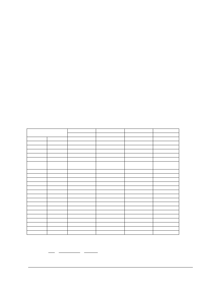
Proposed chemical compositions are given in table 1. The values apply to both ladle and product analysis.
Deviations from this proposal shall be agreed in each case.
- Ladle analysis shall be determined for each ladle
- Product analysis shall be determined for each ingot
Table 1 – Chemical composition
355 420 460 500
Element\Grade
ladle/product ladle/product ladle/product ladle/product
C
max
0,12 0,14 0,12 0,12
Mn
max
1.65 1,65 1,60 1,60
Si
max
0,35 0,35 0,35 0,35
S
max
0,005 0,007 0,007 0,007
P
max
0,015 0,015 0,015 0,015
Cu
max
0,30 0,30 0,30 0,30
Ni min
max
0,35
0,70
0,35
0,70
0,8
2,8
0,8
2,8
Cr
max
0,20 0,20 0,95 0,95
Mo
max
0,08 0,25 0,50 0,50
V
a)
max
0,050 0,050 0,050 0,050
Nb
a)
max
0,030 0,030 0,030 0,030
Ti
max
0,020 0,020 0,020 0,020
Al
tot.
max
0,040 0,040 0,040 0,040
N
max
0,010 0,010 0,010 0,010
Sb
max
0,010 0,010 0,010 0,010
Pb
max
0,005 0,005 0,005 0,005
Sn
max
0,020 0,020 0,020 0,020
As
max
0,020 0,020 0,020 0,020
Bi
max
0,005 0,005 0,005 0,005
B
max
0,0005 0,0005 0,0005 0,0005
CEV
max
0,45 0,47 0,55 0,55
Pcm
max
0,22 0,22 0,27 0,27
All values are maximum values unless a range is given, all in weight percent.
15
Ni
Cu
5
V
Mo
Cr
6
Mn
C
CEV
+
+
+
+
+
+
=

NORSOK standard M-123
Rev. 1, June 2003
NORSOK standard
Page 8 of 12
5B
10
V
15
Mo
60
Ni
20
Cr
Cu
Mn
30
Si
C
Pcm
+
+
+
+
+
+
+
+
=
0,06%
V
Nb
a)
≤
+
6 Mechanical
testing
6.1 General
Testing for mechanical properties as yield strength, ultimate tensile strength, elongation, reduction of area
and charpy impact energy shall be performed for each forging above 1 ton weight. For smaller forgings,
another test frequency may be agreed upon. The results obtained shall comply with the requirement given
in table
2.
6.2 Test
coupons
Each forging to be tested shall have full section prolongations for test coupons to represent the thinnest and
thickest sections. The test coupons
shall not be removed from the forgings until all quality heat treatments
have been carried out. If batch testing is accepted, one or more sacrificial forgings shall normally act as test
coupons.
6.3 Test
sampling
Unless otherwise agreed, the longitudinal axis and mid-length of test pieces shall be positioned as follows,
see table 3:
- for thickness, t, up to and including 50 mm, the axis shall be at the t/2 and with the mid-length of the test
piece at least 50 mm from the end
- for thickness greater than 50 mm, the axis shall be at t/3 or 80 mm, whichever is less, and at sub surface,
and with mid-length of the test piece at least 50 mm from the end.
Transverse and longitudinal tests are normally to be made except that rings, hollow forgings which are
expanded, and disks are to be tested in tangential and longitudinal direction if length enough for longitudinal
testing.
For each position and orientation described, a set of tests comprise 1 tensile test and 3 charpy V-notch test
specimens.
The supplier shall prepare sketches for purchaser’s acceptance showing location and sizes of the
prolongations or sacrificial forgings and the location of all test specimens within them.
6.4 Test
methods
The tensile testing shall be carried out according to ISO 6892 or equivalent.
The charpy V-notch impact testing shall be carried out according to ISO 148 or equivalent. The notch shall
always be perpendicular to the surface.
6.5
Retesting and criteria for rejection
If one or more of the results fails to meet the requirements, the manufacturer may carry out double set of
additional tests, preferably from the same test coupon and position. All results from retest shall meet the
requirements.
If retesting fails, the forging will be rejected. However the manufacturer may choose to carry out a full reheat
treatment (e.g. normalizing + tempering or quenching + tempering) once followed by full set of mechanical
testing. If any results still are not acceptable, the forging or lot will be rejected.
NORSOK standard M-123
Rev. 1, June 2003
NORSOK standard
Page 9 of 12
6.6 Mechanical
properties
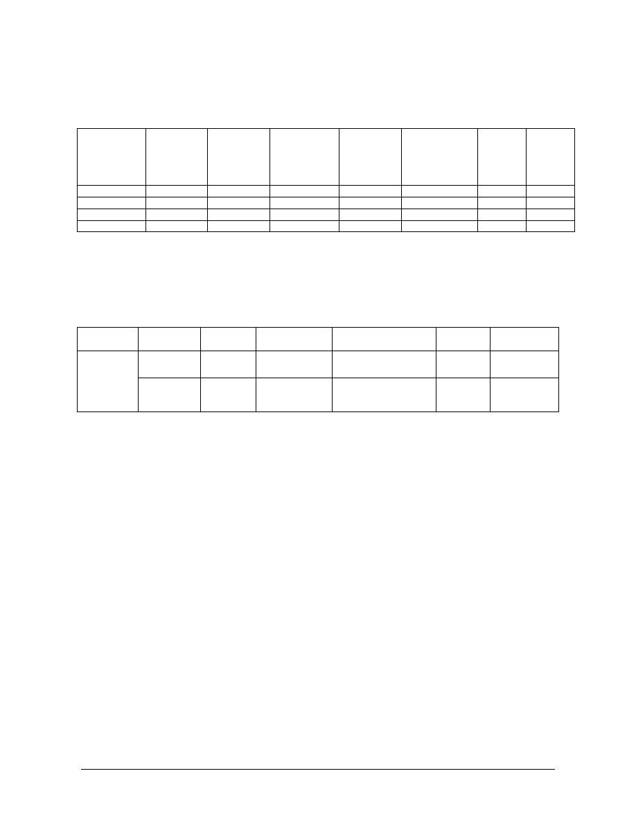
Requirements to mechanical properties are given in table 2.
Table 2 – Mechanical properties
Steel grade
Yield
strength
R
e
min
MPa
Tensile
strength
R
m
min
MPa
Elongation
A
5
min
%
Reduction
of area
Z min
%
Impact test
KV min
J aver./single
KV test
temp.
o
C
Ratio
R
e/
R
m
max
355 355
470-630
22 50 50/42 -40
0,87
420 420
500-660
19 40 50/42 -40
0,90
460 460
540-700
17 40 50/42 -40
0,90
500 500
600-750
17 40 50/42 -40
0,90
For section thicknesses above 250 mm, lower values for R
e
and R
m
may be agreed
R
e
= R
eH
or R
p0,2
6.7
Summary of mechanical testing
A summary of mechanical testing is given in Table 3
Table 3 – Summery of mechanical testing
Test Forging
Weight
Material
thickness
Test frequency Orientation
Test
position
Clause
< 1 tonne
< 1 tonne
≤
50 mm
> 50 mm
To be agreed
To be agreed
Transv. and longit.
Transv. and longit.
t/2
t/3
6.1 and 6.3
6.1 and 6.3
Tensile
and impact
test
> 1 tonne
> 1 tonne
≤
50 mm
> 50 mm
Per forging
Per forging
Transv. and longit.
Transv. and longit.
t/2
t/3 + Sub
surface
6.1 and 6.3
6.1 and 6.3
7
Non destructive testing
7.1 Personnel
Personnel performing NDT in accordance with this standard shall be qualified level II in accordance with NS-
EN 473 / Nordtest or equivalent in the relevant industrial sector.
Personnel shall have prior knowledge to the method by which the forgings are produced, and shall have
access to all drawings defining the location of the critical zones.
An EN-473 / Nordtest or equivalent level III person shall be responsible for all NDT-activity.
7.2
Critical areas and extent of testing
7.2.1 Critical
area
The item for inspection shall be divided into two areas with regard to the criticality of the construction. The
most critical Area 1 shall be specified on drawings supplied by the purchaser. All other areas are defined as
Area 2.
NORSOK standard M-123
Rev. 1, June 2003
NORSOK standard
Page 10 of 12
7.2.2
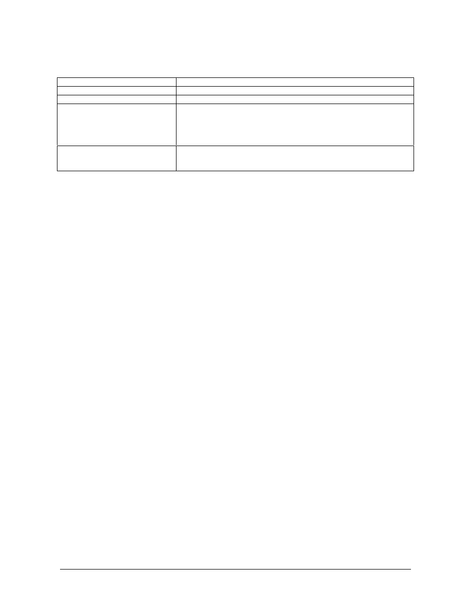
Extent of testing
Table 3 – Extent of non destructive testing
Test method
Extent of testing
Visual examination
100% of accessible surfaces
Magnetic particle testing
100% of accessible surfaces
Ultrasonic testing
100 % volumetric testing from all accessible surfaces at a production
stage with simple configuration and best detectability of imperfections.
The volume shall be divided into Core-zone & Rim-zone. The core zone
is the mid 1/3 cross-section and the remaining volume is rim-zone. For
cross-sections less than 60mm,all will be considered as rim-zone.
Radiographic testing
100 % of bevel ends with thicknesses < 50 mm, within 100 mm from
ends and/or critical areas as agreed between the manufacturer and
purchaser.
7.3 Methods
7.3.1 General
All Non Destructive Testing shall be carried out in final heat treated condition and in accordance with
established procedures. Surface to be inspected shall be clean and free from oil, grease, sand and loose
rust or scale that may interfere a satisfactory inspection.
7.3.2 Visual/dimensional
examination
Methods for visual and/or dimensional examination shall be agreed and specified on approved drawing.
7.3.3
Magnetic particle testing
The performance shall be as per ASME V, art.7/ASTM E 709. The surface to be examined shall be
machined to a roughness better than N 10 (Ra 12
µ
m), ref. ISO 2632 / III.
The tangential field strength shall be min. 25 Oersted and lifting power (AC- Yoke) min. 45N at the maximum
pole spacing that will be used.
7.3.4 Ultrasonic
testing
The performance shall be as per ASTM A388 with the following specified details:
Surfaces:
•
Machined, better than N10 ( Ra 12
µ
m ) ref. ISO 2632 / III for straight beam and better than N9 (Ra 6
µ
m) for angle beam testing.
Probes:
•
2-4MHz,straight beam and/or angle beam.
•
Straight
beam:
Ø10-24
•
Angle beam: Preferred probes:20x22mm or 8x9mm.
Probe selection:
•
Straight beam, scanning in two perpendicular directions.
•
If not possible due to difficult configurations: Additional testing with angle probes.
Sound attenuation ( permeability ):
•
To be checked at different typical locations (cross-sections) of the forging. Any attenuation differences
shall be considered during the testing.
Reference block:
•
Similar to the item inspected related to surface and acoustic response
•
One-block technique: A reference block representing the thickest part of the item tested, containing a flat
bottom hole (FBH) Ø3x15mm and a side drilled hole (SD) Ø3x40mm at a distance of 1/4 x cross-section.
NORSOK standard M-123
Rev. 1, June 2003
NORSOK standard
Page 11 of 12
DGS-method:
•
Alternatively, the DGS-method may be used if agreed between the purchaser and manufacturer. Gain
reference level: Ø3mm equivalent reflector.
7.3.5 Radiographic
testing
•
The radiographic testing and calibration shall be carried out in accordance with ASME V, Article 2.
•
In addition to procedure, a shooting sketch shall be prepared prior to the testing.
7.4 Acceptance
criteria
7.4.1 Visual
examination
Requirements to surface conditions shall be agreed and specified on approved drawings.
7.4.2
Magnetic particle testing
•
As a per ASME VIII, div.1,appendix 6
•
No
linear
indications
•
Acceptance criteria are given in table 4
Table 4 – Size and number of defects
Areas Max.
acceptable
Indication size
Max. number of
Defects
Note
Area 1
100 mm²
15/m²
1)
Area 2
500 mm²
5/m²
2)
1) Min. distance between indications shall exceed 10mm in any direction
2) Min. distance between indications shall exceed 25mm in any direction
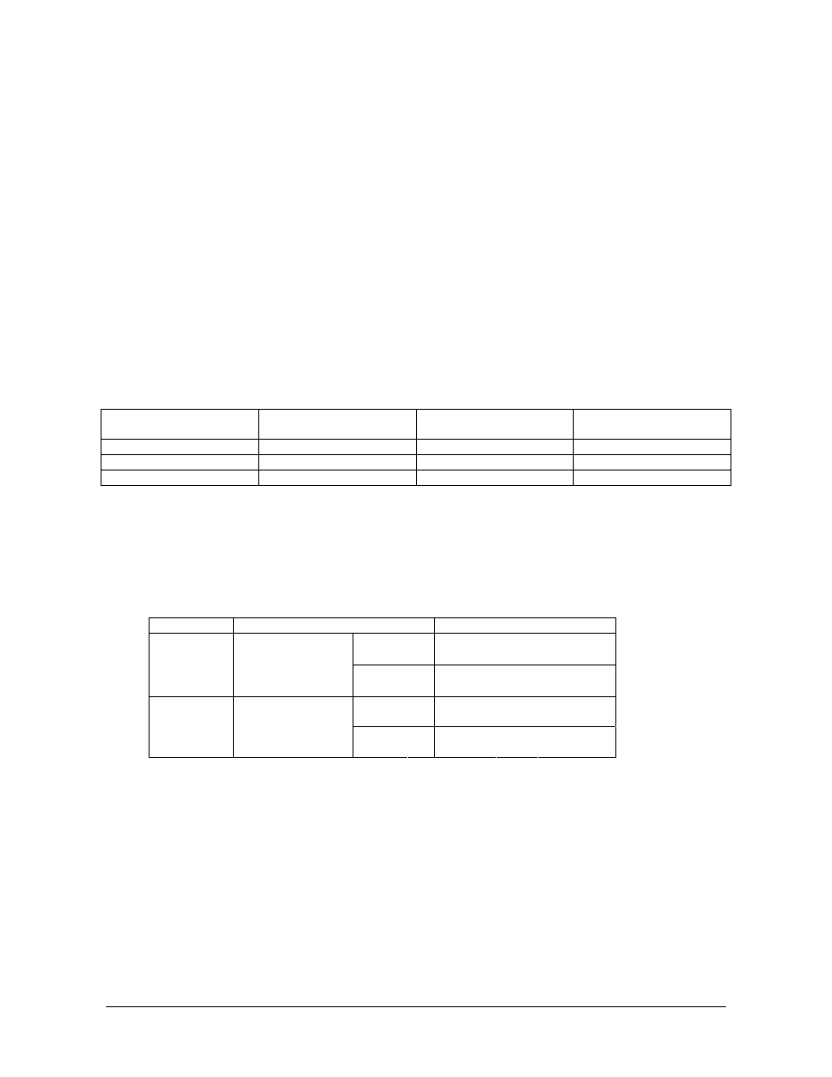
7.4.3 Ultrasonic
testing
Acceptance criteria for ultrasonic testing are given in tables 5
Table 5 – Reference level
Definition
Reference
level
Core-zone Ø3mm
equiv.
disk
reflector
Rim-zone Ø3mm
equiv.
disk
reflector
Area 1
High stressed
area
Core-zone
Ø6mm equiv. disk reflector
Rim-zone Ø3mm
equiv.
disk
reflector
Area 2
Med./low stressed
area
The evaluation of imperfections shall be at the scanning reference-level related to actual depth.
7.4.4 Radiographic
testing
•
Acceptance criteria shall conform to ASME VIII div.1, appendix 7.
•
Cracks and any other type of defects are not acceptable.

NORSOK standard M-123
Rev. 1, June 2003
NORSOK standard
Page 12 of 12
8 Repair
Surface grinding is acceptable according to the following:
Definition
Welding
Max
grinding
Area
1 High
stressed No
0,6mm
Area
2 Moderate/low
stressed
No 1,0mm
Other kind of repair is not accepted. All repaired areas shall be magnetic particle inspected in accordance
with Clause 7.
9 Dimensions/tolerances
Dimensions and required tolerances shall be as given on the relevant drawing of the forgings or other
information supplied.
10 Surface
protection
All machined surfaces shall be protected by a rust protection coating (tectyl or equivalent).
11 Marking
Forgings shall be marked for identification against a certificate. The marking shall include Contractor’s
identification and heat number.
All markings shall be carried out by die stamping and be framed by white painting. The letters used for the
stamping should be 15 mm in height.
12 Documentation
Certificate according to EN 10204 3.1B is required.
The certificate shall contain all relevant information including, but not restricted to the following:
•
purchaser’s name and order number;
•
delivery
condition;
•
heat number/forging number;
•
description of product, dimension and weight;
•
yield strength, tensile strength, elongation and reduction of area;
•
Charpy V-notch values and test temperature;
•
chemical composition, carbon equivalent/Pcm;
•
visual inspection and NDT, or reference to separate reports;


Wyszukiwarka
Podobne podstrony:
NORSOK M 601 ENG
NORSOK S 002 ENG
NORSOK S 012 ENG
NORSOK S 003 ENG
NORSOK M 501 ENG
NORSOK M 001 ENG
NORSOK M 120 ENG
NORSOK S 001 ENG
NORSOK M 503 ENG
NORSOK M 122 ENG
NORSOK S 006 ENG
chrystus jest zyciem mym ENG
Przegląd rozwiązań konstrukcyjnych wtryskarek (ENG)
Assembler ENG
Frequenzimetro eng 2003
123 607 pol ed01 2007
130507143708 bbc tews 123 born yesterday
PM [R2] Sylabus ENG
04 2005 123 124
więcej podobnych podstron