
GD&T Free Resource: Geometric Dimensioning and Tolerancing (GD&T) Glossary of Symbols and Terms - ASME Y14.5-2009
GD&T Free Resource Geometric Dimensioning and Tolerancing (GD&T) Glossary of Symbols and Terms - ASME Y14.5-2009.htm[2019-08-28 18:57:32]
GD&T Glossary
(Based on ASME Y14.5-2009)
GD&T (geometric dimensioning and tolerancing) is an international language that is used on engineering
drawings to accurately describe the size, form, orientation, and location of part features. It is also a design-
dimensioning philosophy that encourages designers to define a part based on how it functions in the final
product or assembly.
GD&T is an exact language that enables design engineers to "say what they mean" on a drawing, thus
improving product designs and lowering cost. Process engineers and manufacturing use the language to
interpret the design intent and to determine the best manufacturing approach. Quality control and
inspection use the GD&T language to determine proper set-up and part verification.
By providing company-wide uniformity in the drawing specifications and interpretation, GD&T reduces
controversy, guesswork, and assumptions throughout the design, manufacturing and inspection process.
Understanding how to apply and interpret GD&T correctly will help you:
Create clear, concise drawings
Improve product design
Create drawings that reduce controversy, guesswork, and assumptions throughout the
manufacturing process
Effectively communicate or interpret design requirements for suppliers and manufacturing
However, because GD&T is such a precise language, it involves a great many symbols and terms.
Here is a list of some of the topics involved in geometric dimensioning and tolerancing
fundamentals and a short definition of each.
The following terms are related to GD&T. Unless otherwise noted, the definition is from
ASME Y14.5M-2009.
DO YOU UNDERSTAND THE 2009 STANDARD CHANGES?
ETI offers a variety of resources to help you understand the new features in the ASME
Y14.5-2009 Standard:
Attend a Fundamentals of GD&T workshop
Order a
2009 Ultimate GD&T Pocket Guide
Order a
1994-2009 New Features Comparison Chart
Actual Local Size - The measured value of any individual distance at any cross section of a feature
of size.
Actual Mating Envelope - This envelope is outside the material. A similar perfect feature(s)
counterpart of smallest size that can be contracted about an external feature(s) or largest size that
can be expanded within an internal feature(s) so that it coincides with the surface(s) at the highest
points. There are two types of actual mating envelopes: related and unrelated.
Actual Minimum Material Envelope - This envelope is within the material. A similar perfect
feature(s) counterpart of largest size that can be expanded within an external feature(s) or smallest
Home
Home
About ETI
About ETI
Demos
Demos
Blog
Blog
Newsletter
Newsletter
Support
Support
Contact Us
Contact Us
Why Choose ETI?
Why Choose ETI?
Software
Software
Products
Products
Engineering Services
Engineering Services
Web-Based Training
Web-Based Training
On-Site Training
On-Site Training
Public Seminars
Public Seminars
Live Web Training
Live Web Training
GD&T Resources
GD&T Resources
SAE Courses
SAE Courses
Search
GD&T Free Resource: Geometric Dimensioning and Tolerancing (GD&T) Glossary of Symbols and Terms - ASME Y14.5-2009
GD&T Free Resource Geometric Dimensioning and Tolerancing (GD&T) Glossary of Symbols and Terms - ASME Y14.5-2009.htm[2019-08-28 18:57:32]
size that can be contracted about an internal feature(s) so that it coincides with the surface(s) at
the lowest points. There are two types of actual mating envelopes: unrelated and related.
All-Around Symbol - The symbolic means of indicating that a tolerance applies to
surfaces all around the part is a circle located at the junction of a leader from the
feature control frame.
All-Over Symbol - The symbolic means of indicating that a profile tolerance zone applies to all
surfaces, all over the three-dimensional profile of a part.
Angularity - The condition of a surface, feature’s center plane, or feature’s axis at
any specified angle from a datum plane or datum axis.
Angularity Tolerance - A geometric tolerance that limits the amount a surface, axis, or center
plane is permitted to deviate from a basic angle relative to a datum reference frame.
Annotation - Dimensions, tolerances, notes, text, or symbols visible without any manual or external
manipulation.
Annotation Plane - A conceptual plane containing annotation that either perpendicularly intersects
or is coincident with one or more surfaces of a feature.
Arc - A segment of a curve.
ASME Y14.41-2012 - American Society of Mechanical Engineers Standard on Digital Product
Definition Data Practices.
ASME Y14.5-2009 - The national standard for dimensioning and tolerancing in the United States.
ASME stands for American Society of Mechanical Engineers. The Y14.5 is the standard number,
and 2009 is the date the standard was officially approved.
ASME Y14.5M-1994 - The national standard for dimensioning and tolerancing in the United States.
ASME stands for American Society of Mechanical Engineers. The Y14.5 is the standard number.
"M" is to indicate the standard is metric, and 1994 is the date the standard was officially approved.
ETI's Ultimate GD&T Pocket Guides
The Ultimate GD&T
Pocket Guide is a handy
reference tool in one
convenient pocket-sized
package.
Carry it with you on the
job and have a resource
to all your GD&T
questions at your
fingertips.
The new pocket guide
includes all the topics
from the 1994 version
plus updates to the 2009
Standard and 50% more
content.
Spiral-bound, more
content, includes index
tabs for on-the-job
functionality.
Assembly - A number of parts, or combination thereof, that are joined together to perform a
specific function and subject to disassembly without degradation of any of the parts (e.g., power
shovel-front, fan assembly, audio frequency amplifier).
Assembly Model - A model in which the product described is an assembly of two or more items.
GD&T Free Resource: Geometric Dimensioning and Tolerancing (GD&T) Glossary of Symbols and Terms - ASME Y14.5-2009
GD&T Free Resource Geometric Dimensioning and Tolerancing (GD&T) Glossary of Symbols and Terms - ASME Y14.5-2009.htm[2019-08-28 18:57:32]
Associated Entities - The portion of a product definition to which annotation applies.
Associated Group - A user defined set of related digital elements.
Associativity - The established relationship between digital elements.
Attribute - A dimension, tolerance, note, text, or symbol required to complete the product definition
or feature of the product that is not visible but available upon interrogating the model.
Attribute Data - Information obtained from an inspection process that indicates only whether a part
is acceptable or not acceptable.
Attribute Gage - The family of receiver gages used to collect attributes data; for example, GO and
functional gages.
Average Diameter - The average of several diametric measurements across a circular or
cylindrical feature.
AVG - Placed near the qualified size dimension where a form control (such as circularity) is
specified in a free state. It is then used to ensure that the actual diameter of the feature can be
restrained to the desired shape at assembly.
Axis - A theoretical straight line about which a geometric object rotates or may be imagined to
rotate. Where the term “axis” is used in this text, unless otherwise indicated, it refers to the axis of
the unrelated actual mating envelope of a cylindrical feature of size.
Axis/Center Plane Interpretation - A straight line that coincides with the axis of the true geometric
counterpart of the specified feature.
Axis of Feature - A straight line that coincides with the axis of the true geometric counterpart of the
specified feature.
Axis Offset - The parallel distance between two axes; for example, the distance between a part
feature of size axis and a datum axis.
Axis Theory - When the axis (or center plane) of the feature of size must be within the tolerance
zone.
Basic Angle - A type of basic dimension with an angular value used to define the orientation of a
part feature or datum target.
Basic Dimension - The axis (or center plane) of the unrelated actual mating
envelope of the feature of size must be within the tolerance zone.
Between Symbol - The axis (or center plane) of the unrelated actual mating
envelope of the feature of size must be within the tolerance zone.
Bidirectional Position Tolerance - Bidirectional Position Tolerance.
Bilateral Equally Disposed Tolerance Zone - A tolerance zone that is equally divided bilaterally to
both sides of the true profile.
Bilateral Unequally Disposed Tolerance Zone - An unequally disposed tolerance zone is
indicated with an unequally disposed profile symbol in the feature control frame following the
tolerance value. A second value after the symbol indicates the tolerance in the direction that adds
material to the true profile.
GD&T Free Resource: Geometric Dimensioning and Tolerancing (GD&T) Glossary of Symbols and Terms - ASME Y14.5-2009
GD&T Free Resource Geometric Dimensioning and Tolerancing (GD&T) Glossary of Symbols and Terms - ASME Y14.5-2009.htm[2019-08-28 18:57:32]
Bilateral Tolerance - A type of plus-minus tolerance that allows a dimension to vary in both the
plus and minus directions.
Bilateral Tolerance Zone - A tolerance zone that is divided bilaterally to both sides of the true
profile.
Bonus Tolerance - A potential additional tolerance for a geometric tolerance.
Boundary - A keyword used with a position tolerance on to denote that only a boundary
interpretation exists for the position tolerance. There is no axis interpretation.
"By" Symbol - A symbol that indicates a relationship between two coordinate dimensions.
Cartoon Gage - A simplified sketch of a functional gage.
Center Plane - A theoretical plane about which a geometric object is equally disposed. Where the
term “center plane” is used, unless otherwise indicated, it refers to the center plane of the unrelated
actual mating envelope of a width feature of size.
Circular Runout Tolerance - A geometric tolerance that limits the high to low point deviation
(runout) of the circular elements of any surface of revolution or the circular elements of a planar
surface that is perpendicular to and intersects the datum axis. The tolerance zone (runout) applies
independently at each circular element of the toleranced surface (i.e., at each cross section
perpendicular to the datum axis).
Circularity - The condition of a surface where: a) For a feature other than a sphere
(e.g., cylinder, cone, etc.), all points of the surface intersected by any plane
perpendicular to an axis or spine (curved line) are equidistant from that axis or spine
(curved line). b) For a sphere, all points of the surface intersected by any plane
passing through a common center are equidistant from that center.
Circularity Tolerance - A geometric tolerance that limits the circularity deviation (radial deviation
between highest and lowest points) on individual circular elements.
Coaxial Datum Features - Coaxial diameters used to create a single datum axis.
Coaxial Diameters - Two (or more) diameters that are shown on the drawing as being on the same
center line (axis).
Coaxiality - The condition where the axes of the unrelated actual mating envelopes, axis of the
unrelated minimum material envelope, or median points (as applicable) of one or more surfaces of
revolution are coincident.
Learn more about our GD&T training software
Commercial and Government Entity (CAGE) Code - A five character code that provides a unique
activity identifier used by the government for activity identification.
Composite Position Tolerancing - A multiple-segment feature control frame with one position
symbol.
Complex Feature - A single surface of compound curvature or a collection of other features that
constrains up to six degrees of freedom.
Composite Position Tolerance - A single surface of compound curvature or a collection of other
features that constrains up to six degrees of freedom.
Composite Profile Tolerance - A feature control frame that contains multiple segments with a
single entry of a position tolerance that is applicable to all horizontal segments of the feature
control frame.
GD&T Free Resource: Geometric Dimensioning and Tolerancing (GD&T) Glossary of Symbols and Terms - ASME Y14.5-2009
GD&T Free Resource Geometric Dimensioning and Tolerancing (GD&T) Glossary of Symbols and Terms - ASME Y14.5-2009.htm[2019-08-28 18:57:32]
Concentricity - The condition where the median points of all diametrically opposed
elements of a surface of revolution (or the median points of correspondingly located
elements of two or more radially disposed features) are congruent with the datum
axis (or center point).
Concentricity Tolerance - A geometric tolerance that defines the permissible deviation that all
median points of a surface of revolution (or correspondingly located elements of two or more
radially disposed features) are permitted to vary from a datum axis or center point.
Conical - A surface of revolution that has a taper symmetrical about its axis. See conical taper.
Conical Taper - The ratio of the difference in the diameters of two sections (perpendicular to the
axis) of a cone to the distance between these sections. See ASME Y14.5-2009 paragraph 2.13 for
acceptable methods of dimensioning.
Conicity - A profile tolerance applied to a conical surface to control form, or combination of size,
form, orientation, and location.
Constraint - A limit to one or more degrees of freedom.
Continuous Feature Symbol - A symbol that indicates where a group of two or more features of
size are to be treated geometrically as a single feature or feature of size.
Controlled Radius - A radius where the part surface must have a smooth curve
within the tolerance zone. In a controlled radius, no flats or reversals are permitted
on the arc surface.
Coordinate Measuring Machine (CMM) - A precision three-axis machine used to collect and
analyze surface points from a part to verify the geometric requirements (size, location, orientation,
and form) of part features.
Coordinate Tolerancing - A dimensioning system where the coordinates (X,Y,Z) of the centers of
features of size and surfaces are located (or defined) by means of linear dimensions with plus-
minus tolerances.
Coplanar Datum Features - Two or more planar datum features that are on the same plane.
Coplanarity - The condition of two or more surfaces having all elements in one plane.
Copy - Any reproduction or duplication, in any media, of the original.
Counterbore - A flat-bottomed diameter.
Counterbore Symbol - Symbolic means of indicating a counterbore.
Countersink - An angular lead-in to enlarge and bevel the top of a hole so that a screw, or bolt can
be inserted flush with the surface.
Countersink Symbol - Symbolic means of denoting the shape of geometry on a part.
Cylindricity - The condition of a surface of revolution in which all points of the
surface are equidistant from a common axis.
Cylindricity Gage - An instrument used to measure cylindricity deviation.
Cylindricity Tolerance - A geometric tolerance that defines the deviation permitted on a cylindrical
surface. A cylindricity tolerance applies along the entire cylindrical surface simultaneously.
GD&T Free Resource: Geometric Dimensioning and Tolerancing (GD&T) Glossary of Symbols and Terms - ASME Y14.5-2009
GD&T Free Resource Geometric Dimensioning and Tolerancing (GD&T) Glossary of Symbols and Terms - ASME Y14.5-2009.htm[2019-08-28 18:57:32]
Data - Information represented in a formal manner suitable for communication, interpretation, or
processing by human beings or computers.
Datum - A theoretically exact plane, point or axis from which a dimensional measurement is made.
Datum Axis - The axis of a datum feature simulator established from the datum feature.
Datum Center Plane - The center plane of a datum feature simulator established from the datum
feature.
Datum Center Point - The center point of a datum feature simulator established from the datum
feature.
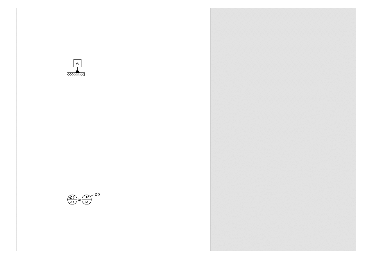
Datum Feature - A feature or feature of size that is identified with either a datum
feature symbol or a datum target symbol.
Datum Feature Reference - The desired order of precedence is indicated by entering the
appropriate datum feature reference letter, from left to right, in the feature control frame.
Datum Feature Shift - The allowable movement or looseness between the part datum feature and
the datum feature simulator.
Datum Feature Simulator (Physical) - The physical boundary used to establish a simulated datum
from a specified datum feature.
Datum Feature Simulator (Theoretical) - The theoretically perfect boundary used to establish a
datum from a specified datum feature.
Datum Plane - A datum established from the datum feature simulator of a nominally flat datum
feature. It constrains three degrees of freedom (one translation and two rotations).
Datum Reference Frame - A set of three mutually perpendicular datum planes. The datum
reference frame provides direction as well as an origin for dimensional measurements.
Datum Reference Frame Symbol - A symbol used to label axes of a datum reference frame. The
X, Y, Z labels represent the translational degrees of freedom.
Datum Shift - The allowable movement or looseness between the part datum feature and the
datum. The datum feature shift / displacement shall always be limited or constrained by the datum
feature simulator.
Datum System - A set of symbols and rules on how to constrain a part to establish a relationship
between the part and geometric tolerance zones.
Datum Target - A set of symbols that describe the shape, size, and
location of datum feature simulators that are used to establish datum
planes, axes, or points.
Datum Target Area - A designated area used in establishing a datum.
Datum Target Identification System - A means of designating a datum target on a drawing. The
symbol is paced outside the part outline with a radial line directed to the target.
Datum Target Line - A designated line used in establishing a datum.
Datum Target Point - A designated point used in establishing a datum.

GD&T Free Resource: Geometric Dimensioning and Tolerancing (GD&T) Glossary of Symbols and Terms - ASME Y14.5-2009
GD&T Free Resource Geometric Dimensioning and Tolerancing (GD&T) Glossary of Symbols and Terms - ASME Y14.5-2009.htm[2019-08-28 18:57:32]
Datum Target Symbol - A circular symbol with a horizontal line dividing the symbol into two halves.
The bottom half denotes the datum letter and the target’s number. The top half denotes the datum
feature simulator size, when applicable.
Degrees of Freedom (DOF) - The movement of a part in space. A rigid part has six degrees of
freedom: three translational degrees of freedom and three rotational degrees of freedom.
Depth - Refers to how deep a feature is on a part.
Depth Symbol - Indicates the depth of a hole, counterbore, or spotface.
Derivative - A symbol that describes the shape, size, and location of gage elements that are used
to establish datum planes or axes.
Derived Median Line - An imperfect line formed by the center points of all cross sections of a
feature of size.
Derived Median Plane - An imperfect plane formed by the center points of all line segments
bounded by the feature of size.
Design Model - A symbol that describes the shape, size, and location of gage elements that are
used to establish datum planes or axes.
Dial Indicator - An instrument used to accurately measure small linear distances, frequently used
in inspection of parts.
Diameter - The length of a straight line that passes through the center of a circle or cylinder and
touches two points on its edge.
Diameter Symbol - A symbol that describes the shape, size, and location of gage elements that
are used to establish datum planes or axes.
Die Closure - A symbol that describes the shape, size, and location of gage elements that are used
to establish datum planes or axes.
Digital Data - A symbol that describes the shape, size, and location of gage elements that are used
to establish datum planes or axes.
Digital Element - A symbol that describes the shape, size, and location of gage elements that are
used to establish datum planes or axes.
Dimension - A numerical value(s) or mathematical expression in appropriate units of measure used
to define the size, location, orientation, or form (shape) of a feature (i.e., surface) or feature of size.
Draft - A numerical value expressed in appropriate units of measure and used to define the size,
location, orientation, form, or other geometric characteristics of a part.
Drawing - An engineering document or digital data file(s) that discloses (either directly or by
reference) by means of graphic or textural presentations, or by combinations of both, the physical
or functional requirements of an item.
Drawing Format - The arrangement and organization of information within a drawing. This includes
such features as the size and arrangement of blocks, notes, lists, and revision information and the
use of optional or supplemental blocks.
Elongated Hole - A hole with a different length and width (commonly referred to as a slot).
Engineering Drawing - A document that communicates a precise description of a part. This
description consists of pictures, words, numbers, and symbols.
Equal Bilateral Tolerance - Where the allowable variation from the specified dimension (nominal)
GD&T Free Resource: Geometric Dimensioning and Tolerancing (GD&T) Glossary of Symbols and Terms - ASME Y14.5-2009
GD&T Free Resource Geometric Dimensioning and Tolerancing (GD&T) Glossary of Symbols and Terms - ASME Y14.5-2009.htm[2019-08-28 18:57:32]
value is the same in both directions.
Feature - A physical portion of a part, such as a surface, pin, hole, or slot or its representation on a
drawing, model, or digital data files.
Feature Axis - The axis of the unrelated actual mating envelope of a feature.
Feature Center Plane - The center plane of the unrelated actual mating envelope of a feature.
Click on any link below to learn more about our products
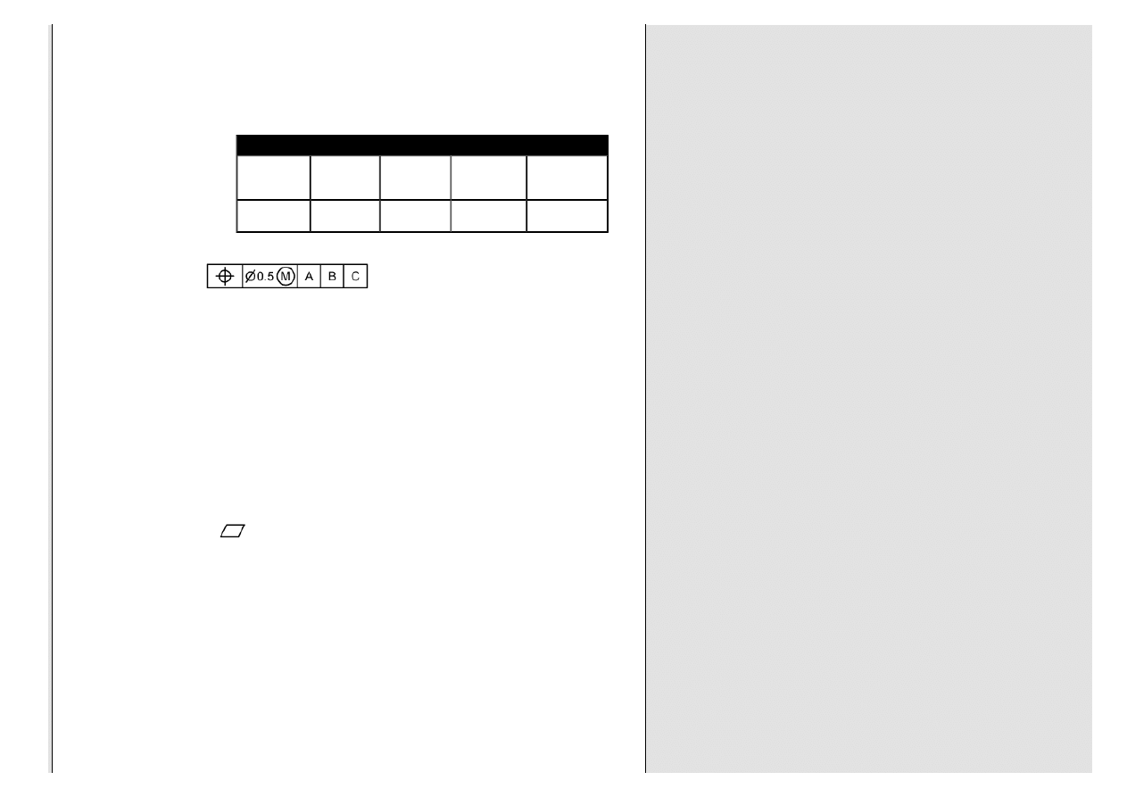
Feature Control Frame - A rectangular box that is divided
into compartments within which the geometric characteristic
symbol, tolerance value, modifiers, and datum references
are placed.
Feature of Size - A general term that is used to refer to either a regular feature of size or an
irregular feature of size.
First Angle Projection - A dimension that is associated with a feature of size.
Fixed Fastener Assembly - An assembly of two or more parts where a fastener is held in place in
(threaded or pressed into) one of the components of the assembly.
Fixed-Limit Gage - A device of defined geometric form and size used to assess the conformance
of a feature of size of a workpiece to a dimensional specification.
Flag Notes - Notes that are located with the general notes but apply only at specific areas or points
on the drawing.
Flash - A geometric tolerance that limits the amount of flatness error a surface is allowed.
Flatness - The condition of a surface having all of its elements in one plane.
Flatness Tolerance - A geometric tolerance that defines the allowable flatness deviation permitted
on a planar surface or derived median plane.
Flats - A straight segment that interrupts an arc.
Floating Fastener Assembly - An assembly of two or more parts where two (or more) components
are held together with fasteners (such as bolts and nuts), and both components have clearance
holes for the fasteners.
Floating Fastener Formula - A formula used to calculate positional tolerance values in a floating
fastener assembly.
T = H - F
Where:
T = position tolerance diameter (for each part)

GD&T Free Resource: Geometric Dimensioning and Tolerancing (GD&T) Glossary of Symbols and Terms - ASME Y14.5-2009
GD&T Free Resource Geometric Dimensioning and Tolerancing (GD&T) Glossary of Symbols and Terms - ASME Y14.5-2009.htm[2019-08-28 18:57:32]
H = MMC of the clearance hole
F= MMC of the fastener
Form Tolerance - A geometric tolerance that defines the allowable flatness deviation permitted on
a planar surface or derived median plane.
Free State - The condition of a part free of applied forces.
Free State Variation - The distortion of a part after removal of forces applied during manufacture.
FRTZF - Feature related tolerance zone framework.The lower segments of a composite control.
Full Indicator Movement - The total movement of an indicator where appropriately applied to a
surface to measure its variations.
Functional Dimensioning - A dimensioning approach that defines a part based on the product (fit
and function) requirements.
Functional Gage - A fixed-limit gage used to verify virtual condition acceptance boundaries.
Fundamental Dimensioning Rules - A set of general rules defined by ASME for dimensioning and
interpreting drawings.
Gage - A device used to measure a part characteristic.
Gage Element - A physical portion of a gage.
Gagemakers' Tolerance - The manufacturing tolerance allowed a gagemaker that is applied to
gages and comparator setting masters.
Gate - A channel in a mold through which molten material flows into the mold cavity.
General Fixed Fastener Formula - (for equally distributed tolerances) is
H = F + 2T or T =
Where:
T = position tolerance diameter
H = MMC of the clearance hole
F = MMC of the fastener
General Notes - Notes that apply to the entire drawing; they are always numbered as a single-
numbered list in the notes area of the drawing.
Geometric Characteristic Symbols - A set of 14 symbols used in the language of GD&T to
describe the geometry attributes of a part.
Geometric Dimensioning and Tolerancing (GD&T) - A symbolic language used on engineering
drawings and CAD models to define part geometry and communicate allowable variation.
Geometric Tolerance - The general term applied to the category of tolerances used to control
form, profile, orientation, location, and runout.
Geometry Attribute - A characteristic of a feature or feature of size.
Go Gage - A fixed-limit gage that checks a feature of size for acceptance within MMC perfect form
boundary.
Great Myth of GD&T - The misconception that geometric tolerancing raises product costs.
Height Gage - A measuring device used for measuring a vertical distance of a feature from a
GD&T Free Resource: Geometric Dimensioning and Tolerancing (GD&T) Glossary of Symbols and Terms - ASME Y14.5-2009
GD&T Free Resource Geometric Dimensioning and Tolerancing (GD&T) Glossary of Symbols and Terms - ASME Y14.5-2009.htm[2019-08-28 18:57:32]
reference surface.
Implied 90° Angle - Where center lines and lines depicting features are shown on a 2D
orthographic drawing at right angles, and no angle is specified.
Implied 90° Basic Angle - A 90° basic angle that applies where center lines of features in a pattern
(or surfaces shown at right angles on a drawing) are located and defined by basic dimensions, and
no angle is specified.
Implied Basic Zero Dimension - Where a center line or center plane of a feature of size is shown
in line with a datum axis or center plane. The distance between the center lines or center planes is
an implied basic zero.
Implied Datum - An assumed plane, axis, or point from which a dimensional measurement is
made.
Implied Parallelism - Where two surfaces are shown parallel on a drawing and the size dimension
controls the parallelism between the surfaces.
Implied Self-Datum - When a geometric tolerance implies that a feature is to be inspected relative
to its perfect counterpart. Example: a position tolerance specified without a datum reference
creates a relationship between the two coaxial features.
Independency Concept - Size and form are independent; Rule #1 does not apply.
Indicator Zero Block - A gage detail that has two parallel surfaces set at a set distance apart.
Individual - Notation used along with an indication of the number of places a datum feature and
either a single feature of size or a pattern of features of size apply on an individual basis.
Inner Boundary (of an internal feature of size) - A worst-case boundary generated by the
smallest feature of size (MMC) minus the effects of the applicable geometric tolerance and any
additional tolerance (bonus) that may apply.
Inner Boundary (of an external feature of size) - A worst-case boundary generated by the
smallest feature of size (LMC) minus the effects of the applicable geometric tolerance and
additional tolerances (bonus) that may apply.
Irregular Feature of Size - A general term for two types of irregular features of size. Type A: a
directly toleranced feature or collection of features that may contain or be contained by an actual
mating envelope that is a sphere, cylinder, or pair of parallel planes.Type B: a directly toleranced
feature or collection of features that may contain or be contained by an actual mating envelope
other than a sphere, cylinder, or pair of parallel planes.
Item - A nonspecific term used to denote any unit or product, including materials, parts, assemblies,
equipment, accessories, and computer software.
Item Identification - The part, identifying number, or descriptive identifier for a specific item along
with the original design activity identification.
Least Material Boundary (LMB) - The limit defined by a tolerance or combination of tolerances
that exists on or inside the material of a feature(s).
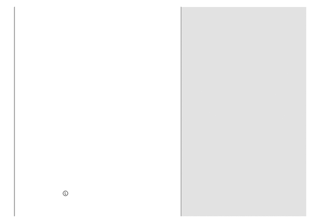
Least Material Condition (LMC) - The condition in which a feature of size contains
the least amount of material everywhere within the stated limits of size.
Limit Dimensioning - Where a dimension has its high and low limits stated. In a limit tolerance, the
high value is placed on top, and the low value is placed on the bottom.
GD&T Free Resource: Geometric Dimensioning and Tolerancing (GD&T) Glossary of Symbols and Terms - ASME Y14.5-2009
GD&T Free Resource Geometric Dimensioning and Tolerancing (GD&T) Glossary of Symbols and Terms - ASME Y14.5-2009.htm[2019-08-28 18:57:32]
Limits of Size - The specified maximum and minimum sizes.
Local Notes - Notes that are located at the specific area or point of application on the drawing.
Location - a) Center to center distance between features of size. b) Location of features of size
from a datum. c) Coaxiality of features of size. d) Concentricity or symmetry of features of size from
a datum axis or plane.
Max Dimension - The drafting symbol for a maximum dimension is the letters “MAX” following the
dimension value; where a maximum dimension is indicated, the opposite end of the specification is
usually zero.
Maximum Material Boundary (MMB) - The boundary established by the collective effects of the
MMC of a datum feature and any applicable tolerances.
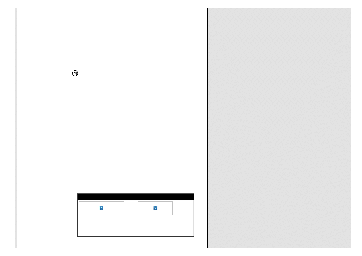
Maximum Material Condition (MMC) - The condition in which a feature of size
contains the maximum amount of material everywhere within the stated limits of size.
May - Used when it is necessary to express nonmandatory provisions.
Measurement Uncertainty - The difference between the corrected measured size and the actual
size. In cases where there is adequate information based on a statistical distribution, the estimate
may be associated with a specific probability.
Median Point - The mid-point of a two-point measurement.
Mismatch - The offset of features on a part caused by misalignment of opposing segments of a
mold or die
.
Model - A combination of design model, annotation, and attributes that describes a product.
Modifiers - Symbols or keywords that communicate additional information about the tolerancing of
a part.
Monodetail Drawing - Delineates a single part.
Movable Datum Target - A datum target with a movable datum target datum feature simulator.
Movable Datum Target Symbol - Indicates that the datum feature simulator is movable.
Multidetail Drawing - Delineates two or more uniquely identified parts in separate views or in
separate sets of views on the same drawing.
Multiple Single-Segment - When two (or more) single-segment feature control frames are stacked
together. Each segment is an independent requirement.
DO YOU NEED GD&T TRAINING? TEST YOUR SKILLS TODAY
Do you know how to use stacks to determine
part distances or assembly conditions? Do
you understand design analysis using
geometric tolerances in stacks?
today.
How well do you know GD&T? Do you know
the symbols, requirements, tolerance
zones, and limitations?
today.
Multiple Single-Segment Position Tolerance - Two or more single-segment position tolerances
applied to the same feature of size or pattern of features of size.
GD&T Free Resource: Geometric Dimensioning and Tolerancing (GD&T) Glossary of Symbols and Terms - ASME Y14.5-2009
GD&T Free Resource Geometric Dimensioning and Tolerancing (GD&T) Glossary of Symbols and Terms - ASME Y14.5-2009.htm[2019-08-28 18:57:32]
Multiple Single-Segment Profile Tolerance - Where two or more profile tolerances are applied to
a surface (or collection of surfaces) relative to different datum reference frames.
NOGO Gage - A fixed-limit gage that checks a feature of size for violation of its LMC actual local
size.
Nominal Size - The designation used for purposes of general identification.
Non-Feature of Size - Not considered a feature of size because the parallel surfaces are not
opposed; they are offset.
Non-Opposed - Two planar surfaces are non-opposed if none of the rays projected from each
surface intersect the other surface.
Non-Uniform Tolerance Zone - A maximum material boundary and least material boundary, of a
unique shape, that encompasses the true profile. The method to indicate a non-uniform tolerance
zone is use the term “NON-UNIFORM” to replace the tolerance value in the feature control frame.
Number of Places Symbol - Symbolic means of indicating how many places a dimension or shape
apply on a drawing.
Opposed - All rays normal from each planar surface intersects the other surface.
Optical Comparator - (Often called a comparator or profile projector) is a device that applies the
use of optics to measure part geometry.
Orientation - The orientation of a feature or a feature of size is its angular relationship to a datum.
Orientation tolerances control parallel, perpendicular, and all other angular relationships.
Orientation Tolerance - A geometric tolerance that limits the amount of orientation error a surface,
axis, or center plane is allowed.
Outer Boundary (of an external feature of size) - A worst-case boundary generated by the
largest feature of size (MMC) plus the effects of the applicable geometric tolerance.
Outer Boundary (of an internal feature of size) - A worst-case boundary generated by the largest
feature of size (LMC) plus the effects of the applicable geometric tolerance.
Parallel - The condition of being an equal distance apart at every point.
Parallelism - The condition where a surface, axis, or center plane is equidistant at all points from a
datum plane or axis.
Parallelism Tolerance - A geometric tolerance that limits the amount a surface, axis,
or center plane is permitted to deviate from parallelism, relative to a datum reference
frame.
Part - One item, or two or more items joined together, not normally subject to disassembly without
destruction or impairment of designed use.
Part or Identification Number - The identifier assigned by the original design activity, or by the
controlling nationally recognized standard, that uniquely identifies a specific item relative to that
design activity.
Partial Datum Reference Frame - Where only one or two datum planes of the datum reference
frame are used.
Partially Opposed - Two planar surfaces are partially opposed if some of the rays projected normal
from each planar surface intersect the other surface.
GD&T Free Resource: Geometric Dimensioning and Tolerancing (GD&T) Glossary of Symbols and Terms - ASME Y14.5-2009
GD&T Free Resource Geometric Dimensioning and Tolerancing (GD&T) Glossary of Symbols and Terms - ASME Y14.5-2009.htm[2019-08-28 18:57:32]
Parting Line -
a) The separation between the mold or die segments, flash fins, or material seepage is
usually produced on the part periphery where the parting line emerges. b) A line on the drawing
representing the mated surfaces of the die or mold segments.
Pattern -
Two or more features or features of size to which a locational geometric tolerance is applied and
is grouped by one of the following methods: nX, INDICATED, n COAXIAL HOLES, ALL OVER, ALL
AROUND, between symbol, n Surfaces, simultaneous requirement.
Perpendicular - A surface, center plane, or axis at a right angle to a datum plane or axis.
Perpendicularity - The condition where a surface, axis, or center plane is exactly 90°
to a datum plane or axis.
Perpendicularity Tolerance - A geometric tolerance that limits the amount a surface axis, or
center plane is permitted to deviate from being perpendicular to a datum. A perpendicularity
tolerance can only constrain rotational degrees of freedom relative to the datum referenced.
Phantom Line - A line consisting of a pattern of a long dash, two short dashes, and a long dash.
Physical Datum Feature Symbol - The physical boundary used to establish a simulated datum
from a specified datum feature.
Planar Feature of Size - A feature of size that contains two features: the two parallel plane
surfaces (such as a width or a thickness). A planar feature of size is one type of a regular feature of
size; capable of producing a center plane.
PLTZF - Pattern locating tolerance zone framework.<br><br>The uppermost segment of a
composite position control. The basic relationship between the features in a pattern and the
referenced datums.
Plus and Minus Tolerance - Where the nominal of the dimension is given first, followed by a plus-
minus expression of a tolerance.
Polygon - A closed plane figure with straight sides.
Position Tolerance - A geometric tolerance that limits the amount the center point, axis, or center
plane of a feature of size is permitted to deviate from true position.
Precision Square - A gage block that has a precise 90
˚ angle between the bottom surface and one
of the sides of the block.
Primary Datum - The first datum referenced in a feture control frame. It is the first datum that the
part contacts in a dimensional measurement.
Profile - An outline of a surface, a shape made up of one or more features, or a two-dimensional
element of one or more features.
Profile of a Line Tolerance - A geometric tolerance that establishes a two-
dimensional tolerance zone that is normal to the true profile at each line element.
Profile of a Surface Tolerance - A geometric tolerance that establishes a three-
dimensional tolerance zone that extends along the length and width (or
circumference) of the considered feature or features.
Projected Tolerance Zone - A tolerance zone that is projected (moved) outside of
GD&T Free Resource: Geometric Dimensioning and Tolerancing (GD&T) Glossary of Symbols and Terms - ASME Y14.5-2009
GD&T Free Resource Geometric Dimensioning and Tolerancing (GD&T) Glossary of Symbols and Terms - ASME Y14.5-2009.htm[2019-08-28 18:57:32]
the feature of size.
Radius - A straight line extending from the center to the periphery of a circle or
sphere.
Reference Dimension - a) A repeat of a dimension b) A dimension derived from other values
shown on the drawing or on related drawings. One method for identifying a reference dimension on
drawings is to enclose the dimension within parentheses.
Regardless of Feature Size - The term that indicates a geometric tolerance or datum reference
applies at any increment of size of the actual mating envelope of the feature of size.
Regardless of Material Boundary - Indicates that a datum feature simulator progresses from the
MMB to the LMB until it makes contact with the extremities of a feature(s).
Regular Feature of Size - One cylindrical or spherical surface, a circular element, a set of two
opposed (or partially opposed) parallel elements, or opposed (or partially opposed) parallel
surfaces, each of which is associated with a directly toleranced dimension (size dimension).
Related Actual Mating Envelope - A similar perfect feature counterpart expanded within an
internal feature of size, or contracted about an external feature of size, while constrained in either
orientation or location (or both) to any applicable datums.
Related Actual Minimum Material Envelope - A similar perfect feature counterpart contracted
about an internal feature(s) or expanded within an external feature(s) while constrained within
orientation or location (or both) to the applicable datum(s).
Restraint - The application of force(s) to a part to simulate its assembly or functional condition
resulting in possible distortion of a part from its free-state condition.
Right-Hand Rule - The right-hand rule works as follows: if you hold the back of your right hand
against a drawing and hold the thumb and index finger at 90° to each other:
The thumb pointing to the right represents the X-axis positive direction.
The index finger pointing to the top of the drawing represents the Y-axis positive direction.
The middle finger pointing at you represents the Z-axis positive direction.
Rotation - Angular movement about an axis.
Roundness (Circularity) Gage - A precision spindle machine used to measure the out of
roundness (circularity deviations) of a surface of revolution.
Rule #1 - The form of an individual regular feature of size is controlled by its limits of size.
Rule #2 - RFS applies with respect to the individual tolerance, and RMB applies, with respect to the
individual datum feature reference, where no modifying symbol is specified.
Click on any link below to learn more about our products

GD&T Free Resource: Geometric Dimensioning and Tolerancing (GD&T) Glossary of Symbols and Terms - ASME Y14.5-2009
GD&T Free Resource Geometric Dimensioning and Tolerancing (GD&T) Glossary of Symbols and Terms - ASME Y14.5-2009.htm[2019-08-28 18:57:32]
Runout - The high to low point deviation of the surface elements relative to a datum axis.
Scale - The ratio of the object size as drawn to its full size.
Secondary Datum - The second datum referenced in a feature control frame. It is the second
datum that the part contacts in a dimensional measurement.
Separate Requirement - This tolerance is verified as a separate inspection item. The part must
meet this requirement to be accepted.
Shall - Establishes a mandatory requirement.
Should - Used when it is necessary to express nonmandatory provisions.
Simulated Datum - A datum established from a physical datum feature simulator.
Simultaneous Requirement - Where two or more geometric tolerances have identical datum
references and are considered a pattern.
Sine Bar - A precision inspection tool used to orient parts at any angle, usually between zero and
sixty degrees. It is so named because the sine of the angle determines the height of a stack of
gage blocks used to set the angle.
Six Degrees of Freedom - Rotation around the X, Y, or Z axis, and movement along the X, Y, or Z
axis.
Size Dimension - A dimension across two opposed (or partially opposed) surfaces, line elements,
or points.
Special-Case Feature of Size Datum - When a feature of size datum feature is referenced at
MMC, but simulated in the gage at a boundary other than MMC.
Spherical Diameter - The length of a straight line that passes through the center of a sphere and
touches two points on its edge.
Spherical Radius - A radius that generates a segment of a sphere.
Spine - A simple (non self-intersecting) curve.
Spotface - The min size of the flat on a flat-bottomed diameter.
Straightness - The condition where an element of a surface or a derived median line
is a straight line.
Straightness of a Line Element - The condition where each line element (or axis or centerplane)
is a straight line.
Straightness Tolerance - A geometric tolerance that, when directed to a surface, limits the amount
of straightness error allowed in each surface line element. A straightness tolerance is applied in the
view where the elements to be controlled are represented by a straight line.
Surface Interpretation - The tolerance zone is a virtual condition (acceptance boundary), located
at true position, which the surface(s) of the tolerance features(s) of size must not violate.
Surface Plate - A solid, flat plate used as the main horizontal reference plane (datum feature
simulator, see Chapter 13) for precision inspection and tooling setup.
Symmetrical Relationship - Where the location deviation of the center plane of a feature of size is
GD&T Free Resource: Geometric Dimensioning and Tolerancing (GD&T) Glossary of Symbols and Terms - ASME Y14.5-2009
GD&T Free Resource Geometric Dimensioning and Tolerancing (GD&T) Glossary of Symbols and Terms - ASME Y14.5-2009.htm[2019-08-28 18:57:32]
being defined relative to a datum center plane. In these cases, a position tolerance may be used to
limit the offset between the center planes.
Symmetry - The condition where all the median points of all opposed
correspondingly located elements of two or more feature surfaces are congruent with
a datum axis or center plane.
Symmetry Tolerance - A geometric tolerance that defines the permissible deviation that median
points of all opposed correspondingly located elements of two or more feature surfaces are
permitted to vary from a datum axis or center plane.
Tangent Plane - A plane that is tangent to the high points of the surface.
Tangent Plane Modifier - The geometric tolerance only applies to the tangent plane of the
toleranced surface.
Tertiary Datum - The third datum referenced in a feature control frame. It is the third datum that the
part contacts in a dimensional measurement.
Theoretical Datum Feature - The theoretically perfect boundary used to establish a datum from a
specified datum feature.
Third Angle Projection - The formation of an image or view upon a plane of projection placed
between the object and the observer.
3-2-1 Rule - A part will have a minimum of three points of contact with its primary datum plane, two
points minimum contact with its secondary datum plane, and a minimum of one point of contact
with its tertiary datum plane.
Tolerance - The total amount a specific dimension is permitted to vary. The tolerance is the
difference between the maximum and minimum limits.
Tolerance Accumulation - A condition where the tolerances from several dimensions combine to
result in a greater amount of tolerance for a part distance.
Tolerance Analysis Chart - A chart that graphically displays the available tolerances of a feature
of size as defined by the drawing specifications.
Tolerance of Position Control - A geometric tolerance that defines the location tolerance of a
feature of size from its true position.
Tolerance Stack - A calculation that determines the theoretical maximum or minimum distance
between two features on a part or in an assembly.
Tolerance Zone - The area (zone) that represents the total amount that part features are permitted
to vary from their specified dimension.
Total Runout - The area (zone) that represents the total amount that part features
are permitted to vary from their specified dimension.
Total Runout Tolerance - A geometric tolerance that limits the high to low point deviation of all
surface elements of a cylindrical surface, or all surface elements of a planar surface that is
perpendicular to and intersects the datum axis.
Translation - The ability to move without rotating.
True Geometric Counterpart - The theoretically perfect boundary (virtual condition or actual
mating envelope) or best fit (tangent) plane of a specified datum feature.

GD&T Free Resource: Geometric Dimensioning and Tolerancing (GD&T) Glossary of Symbols and Terms - ASME Y14.5-2009
GD&T Free Resource Geometric Dimensioning and Tolerancing (GD&T) Glossary of Symbols and Terms - ASME Y14.5-2009.htm[2019-08-28 18:57:32]
True Position - The theoretically exact location of a feature of size defined by basic dimensions.
True Profile - A profile defined by basic radii, basic angular dimensions, basic coordinate
dimensions, basic size dimensions, undimensioned drawings, formulas, or mathematical data,
including design models.
ETI will bring the training to you.
Take a look at our onsite workshops
Unequal Bilateral Tolerance - A tolerance in which the allowable variation from the nominal value
is not the same in both directions.
Unequal Disposed Profile Symbol - Indicates a unilateral or unequally disposed profile tolerance.
Unilateral Tolerance - Where the allowable variation from the nominal value is all in one direction
and zero in the other direction.
Unilateral Tolerance Zone - A tolerance zone that is offset to one side of the material, either “all
outside” or “all inside” of the material.
Unrelated Actual Mating Envelope - A similar perfect feature counterpart expanded within an
internal feature of size or contracted about an external feature of size and not constrained to any
datums.
Unrelated Actual Mating Envelope - External - A similar perfect feature(s) counterpart of smallest
size contracted about an external feature(s) and not constrained to any datum(s).
Unrelated Actual Mating Envelope - Internal - A similar perfect feature(s) counterpart of largest
size that can be expanded within an internal feature(s) and not constrained to any datum(s).
Unrelated Actual Minimum Material Envelope - A similar perfect feature counterpart contracted
about an internal feature(s) or expanded within an external feature(s) and not constrained to any
datum reference frame.
Variable Gaging - Any gaging operation that measures part variation and provides a quantitative
value of the variation.
Virtual Condition (VC) - A fixed-size boundary generated by the collective effects of a considered
feature of size’s specified MMC or LMC and the geometric tolerance for that material condition.
Will - Establishes a declaration of purpose on the part of the design activity.
Worst-case Boundary (WCB) - A general term used to refer to an inner boundary, outer boundary,
or virtual condition.
Zero Tolerance at MMC - A dimensioning method that takes the tolerance stated in the feature
control frame, combines it with the size tolerance, and states a zero tolerance in the feature control
frame.
Truly the Ultimate Pocket Guide on GD&T,
this informative guide is the perfect on-the-job
pocket reference for your GD&T needs. Our
new pocket guide is based on the ASME
Y14.5-2009 Standard. It's an economical
reference tool you can’t afford to be without
and a must for anyone who uses engineering
drawings. Order one for each member of your
team!
GD&T Free Resource: Geometric Dimensioning and Tolerancing (GD&T) Glossary of Symbols and Terms - ASME Y14.5-2009
GD&T Free Resource Geometric Dimensioning and Tolerancing (GD&T) Glossary of Symbols and Terms - ASME Y14.5-2009.htm[2019-08-28 18:57:32]
or click on the pocket
guide to take a look inside.
|
|
|
|
|
|
|
|
Copyright © 1997 - 2018 Effective Training Inc. an
All rights reserved.
This file last modified 11/13/13
Document Outline
- Dysk lokalny
Wyszukiwarka
Podobne podstrony:
DIMENSIONS AND TOLERANCES2 PL
Free Energy Bedini Device And Method For Pulse Charging A Battery Patent Info 2004
Human resources in science and technology
Linear Algebra, Infinite Dimensions, and Maple, Preface
Marxism, the Resource Mobilization Theory, and General?ono
[Mises org]Hayek,Friedrich A A Free Market Monetary System And Pretense of Knowledge(1)
managing corporate identity an integrative framework of dimensions and determinants
Meschini Geometry, Pregeometry and Beyond
Johnsond Carnap, Menger, Popper Explication, Theories Of Dimension, And The Growth Of Scientific
Tourism Human resource development, employment and globalization in the hotel, catering and tourism
Free Resources
Free luggage tag pattern and tutorial
Free Anti Virus Tips and Techniques
A Free Market Monetary System and The Pretense of Knowledge
Henri Bergson Time and Free Will An essay on the Immediate Data of Consciousness
Haisch Geometrodynamics, Inertia and the Quantum Vacuum (2001)
A resource for reading and words
Free Crochet Patterns Rose and Pineapple Bedspread Pattern 2012 03 16
więcej podobnych podstron