C35(i), M35(i), S35
Level 2.5
Repair Documentation
V 0.9
Table of Contents:
1 Introduction
Introduction
The C/M/S35 product family consists of 5 different dualband handsets (GSM-900 and GSM-1800), which can easily be distinguished from the second block of the partnumber printed on the IMEI label. There also exist Asian variants of C/M/S35 named 3508 / 3518 / 3568 respectively. All information below also applies to the Asian variants unless otherwise noted.
Partnumber on IMEI label:
C35 / 3508: S30880-S4000-Xxxx
C35i / 3508i: S30880-S4050-Xxxx
Same as C35 / 3508 but with additional WAP and fax/data capabilities
M35 / 3518: S30880-S4200-Xxxx
M35i / 3518i: S30880-S4250-Xxxx
Same as M35 / 3518 but with additional WAP and fax/data capabilities
S35i / 3568i: S30880-S4100-Xxxx
This manual is intended to help you carry out repairs on level 2.5, meaning limited component repairs. Failure highlights are documented and should be repaired in the local workshops.
It must be noted that all repairs have to be carried out in an environment set up according to the ESD (Electrostatic Discharge Sensitive Devices) regulations defined in international standards.
If you have any questions regarding the repair procedures or spare parts do not hesitate to contact our technical support team in Kamp-Lintfort, Germany:
Tel.: +49 2842 95 4666
Fax: +49 2842 95 4302
e-mail: dominik.schnoor@klf.siemens.de
Antenna Connector
Affected Units
Type: C/M/S35
Affected IMEIs / Date Codes: All / All
Affected SW-Versions: All
Fault Code for LSO reporting: 3ANC
Fault Description
Fault Symptoms for customers:
Network Search when using the external antenna (carkit)
No location update possible on external antenna (carkit)
Fault Symptom on GSM-Tester:
Output power problems on the external antenna
No location update possible
Component Information
The Antenna Connector is a mechanical switch operated by the RF plug of a carkit or, for testing purposes, of an RF clip.
Normally the RF signal goes to and comes from the internal antenna. Whenever an RF plug is plugged into the antenna connector the connection to the internal antenna is opened and the connection to the external antenna socket is made. See drawing below.
Priority:
........ Mandatory
........ Repair
........ Optional
........ Not Yet Defined
Repair Documentation
Description of procedure:
Diagnosis
Check the output power of the handset with the LSO testprogram. Especially watch the external antenna power!
Repair by component change
Use hot air blower to remove defective connector
Avoid excessive heat!
Watch surrounding components!
Resolder new connector afterwards.
Repair by SW-Booting
Not possible!
Test
Retest handset after repair as described above.
List of needed material
Components
X35 antenna connector
Attention: This is not the same connector as C25/S25 !!!
Part-Number: L36334-Z93-C272
Jigs and Tools
Hot Air Blower
Soldering Iron
Special Tools
None
Working materials
Desolder Wick / Braid
Solder
Drawings

Figure 1: X35 Board Antenna Connector Side (Top View)
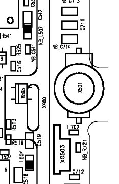
Figure 2: X35 Antenna Connector Placement (X501) (Top View)
Ringer
Affected Units
Type: C/M/S35
Affected IMEIs / Date Codes: All / All
Affected SW-Versions: All
Fault Code for LSO reporting: 3RIN
Fault Description
Fault Symptoms for customers:
Problems with the handset ringer. No ringer tone audible.
Fault Symptom on GSM-Tester:
Handset fails ringer test.
Priority:
........ Mandatory
........ Repair
........ Optional
........ Not Yet Defined
Repair Documentation
Description of procedure:
Diagnosis
Visually check the ringer. Watch for physical damage or dry joints.
Repair by component change
Resolder dry soldering joints.
If the ringer is physically damaged use hot air blower or wick to remove defective connector.
Avoid excessive heat!
Watch surrounding components!
Resolder new ringer afterwards.
Repair by SW-Booting
Not possible!
Test
Retest handset after repair.
List of needed material
Components
Ringer P35:
Part-Number: L36178-Z2-C26
Jigs and Tools
Hot Air Blower
Soldering Iron
Special Tools
None
Working materials
Desolder Wick / Braid
Solder
Flux
Drawings
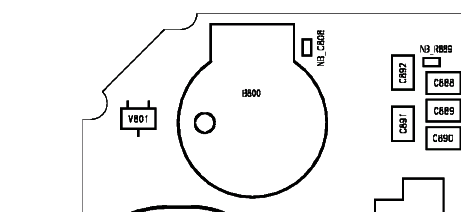
Figure 1: X35 Board Ringer Side
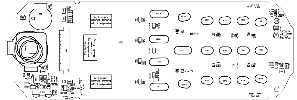
Figure 2: X35 Ringer (B800) Placement (Top View)
Bottom Connector (Lumberg)
Affected Units
Type: C/M/S35
Affected IMEIs / Date Codes: All / All
Affected SW-Versions: All
Fault Code for LSO reporting: 3LUC
Fault Description
Fault Symptoms for customers:
Charging problems.
Problems with external loudspeaker or microphone when using a car kit.
Problems with accessories connected at the bottom connector.
Problems with SW booting.
Fault Symptom on GSM-Tester:
This problem cannot be detected with a GSM-Tester.
Priority:
........ Mandatory
........ Repair
........ Optional
........ Not Yet Defined
Repair Documentation
Description of procedure:
Diagnosis
Visually check the bottom connector. Watch for dry joints!
Repair by component change
Use hot air blower remove defective bottom connector.
Avoid excessive heat!
Watch surrounding components!
Resolder new bottom connector afterwards.
Repair by SW-Booting
Not possible!
Test
Retest handset after repair.
List of needed material
Components
Bottom Connector X35
Part-Number: L36334-Z93-C262
Jigs and Tools
Hot Air Blower
Soldering Iron
Special Tools
None
Working materials
Desolder Wick / Braid
Solder
Drawings
Figure 1: X35 Board Bottom Connector Side
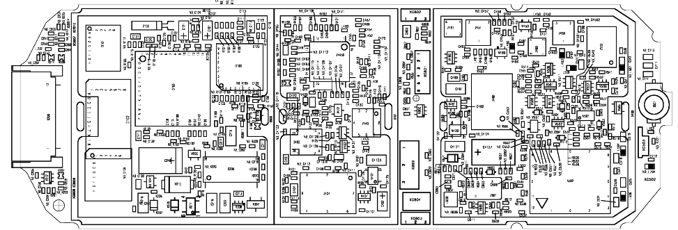
Figure 2: X35 Bottom Connector Placement (Top View)
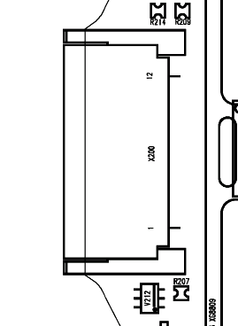
Table 1: X35 Bottom Connector Pin Description
Pin |
Name |
IN/OUT |
Notes |
1 |
GND |
|
|
2 |
SB |
I/O |
Charger coding and charger control.
|
3 |
POWER |
I |
Charging Current
|
4 |
FBatt+ |
O |
Power supply for the accessories.
|
5 |
TX |
O |
Serial interface
|
6 |
RX |
I |
Serial interface
|
7 |
ZUB_CLK |
I/O |
Clock line for accessory bus Use as DTC In data operation
|
8 |
ZUB_DATA |
I/O |
Data line for accessory bus. Use as CTS in data operation
|
9 |
GND_MIC |
|
For external microphone
|
10 |
HF_MIC |
I |
External microphone
|
11 |
AUDO |
O
|
Trigger for external loudspeaker |
12 |
GNDA |
|
For external loudspeaker |
Display Connector
Affected Units
Type: C/M/S 35
Affected IMEIs / Date Codes: All / All
Affected SW-Versions: All
Fault Code for LSO reporting: 3DIC
Fault Description
Fault Symptoms for customers:
Display problems, like missing lines or columns on the LCD or display contrast problems.
Fault Symptom on GSM-Tester:
Display test fails.
Priority:
........ Mandatory
........ Repair
........ Optional
........ Not Yet Defined
Repair Documentation
Description of procedure:
Diagnosis
Visually check the status of the display connector. Watch for oxidation and dry solder joints.
Mechanically check the opening / closing mechanism.
Repair by component change
Use hot air to remove defective connector
Avoid excessive heat!
Watch surrounding components!!
Resolder new connector afterwards
Repair by SW-Booting
Not possible!
Test
Retest handset after repair.
List of needed material
Components Display connector
Part-Number: L36195-Z26-C629
Jigs and Tools
Soldering Iron
Hot Air Blower
Special Tools
None
Working materials
Desolder Wick / Braid
Solder
Drawings
Figure 1: X35 board display connector side
Figure 2: X35 display connector placement (Top View)
Keyboard LEDs
Affected Units
Type: C/M/S 35
Affected IMEIs / Date Codes: All / All
Affected SW-Versions: All
Fault Code for LSO reporting: 3LED
Fault Description
Fault Symptoms for customers:
Keyboard Illumination not working.
Fault Symptom on GSM-Tester:
This fault cannot be detected with a GSM-Tester
Priority:
........ Mandatory
........ Repair
........ Optional
........ Not Yet Defined
Repair Documentation
Description of procedure:
Diagnosis
Use the diode test function of a multimeter to check the status of the diode.
The typical voltage drop on the diode is 1.7V when testing the diode function with the multimeter.
Repair by component change
Use soldering iron to remove defective diode
Avoid excessive heat!
Watch surrounding components!
Resolder new diode afterwards.
Repair by SW-Booting
Not possible!
Test
Retest handset after repair.
List of needed material
Components
LED keyboard X35
Part-Number: L36840-L2031-D670
Jigs and Tools
Hot Air Blower
Soldering Iron
Special Tools
None
Working materials
Desolder Wick / Braid
Solder
Drawings
Figure 1: X35 board keyboard LED Side
Figure 2: X35 keyboard LED placement and polarity (top view)
Display LEDs
Affected Units
Type: C/M/S 35
Affected IMEIs / Date Codes: All / All
Affected SW-Versions: All
Fault Code for LSO reporting: 3LED
Fault Description
Fault Symptoms for customers:
Display Illumination not working.
Fault Symptom on GSM-Tester:
This fault cannot be detected with a GSM-Tester
Priority:
........ Mandatory
........ Repair
........ Optional
........ Not Yet Defined
Repair Documentation
Description of procedure:
Diagnosis
Use the diode test function of a multimeter to check the status of the diode.
The typical voltage drop on the diode is 1.7V when testing the diode function with the multimeter.
Attention: There are two different types of display LEDs, one for C/M35 and one for S35! Also they use different placement location, see drawings 1 and 3.
Repair by component change
Use soldering iron to remove defective diode
Avoid excessive heat!
Watch surrounding components!
Resolder new diode afterwards.
Repair by SW-Booting
Not possible!
Test
Retest handset after repair.
List of needed material
Components
Display LED S35
Part-Number: L36840-L2048-D670
Display LED C/M35
Part-Number: L36840-L2047-D670
Jigs and Tools
Hot Air Blower
Soldering Iron
Special Tools
None
Working materials
Desolder Wick / Braid
Solder
Drawings
Figure 1: C/M35 board display LED Side
Figure 2: C/M35 board display LED placement and polarity
Figure 3: S35 board display LED side
Figure 4: S35 board display LED placement and polarity
Infrared Diodes
Affected Units
Type: S 35
Affected IMEIs / Date Codes: All / All
Affected SW-Versions: All
Fault Code for LSO reporting: 3INF
Fault Description
Fault Symptoms for customers:
No infrared connection possible.
Fault Symptom on GSM-Tester:
This fault cannot be detected with a GSM-Tester.
Priority:
........ Mandatory
........ Repair
........ Optional
........ Not Yet Defined
Repair Documentation
Description of procedure:
Diagnosis
Visually check the status of the IrDa module. Watch for dry solder joints.
Use a reference infrared port (eg. from a notebook) to check the IrDa function. If the notebook recognizes the S35, the infrared function is ok.
Repair by component change
Use hot air to remove defective infrared module.
Avoid excessive heat!
Watch surrounding components!!
Resolder new module afterwards
Repair by SW-Booting
Not possible!
Test
Retest handset after repair.
List of needed material
Components Infrared module S35
Part-Number: L36810-U6030-D670
Jigs and Tools
Soldering Iron
Hot Air Blower
Special Tools
None
Working materials
Desolder Wick / Braid
Solder
Drawings
Figure 1: S35 board infrared module side
Figure 2: S35 infrared module placement (Top View)
Information and Communication Products
Communication Devices
V0.9 Page 29 of 29 ICP CD ST
D. Schnoor
2/00
Pin 1
Pin 12
From Power Amplifier/
To Receiver
To / From Internal Antenna
Wyszukiwarka
Podobne podstrony:
sm S25 lvl V10
Program studiów SM IE
2015 06 podst SM
EMP7700 ASM E B SM
p35 022
Flaminio Costa VS ENEL, stosunki międzynarodowe, sm iii rok
SM ściąga, Politologia WSNHiD, Licencjat, V SEMESTR, Stosunki międzynarodowe
SM ćwiczenia ściaga II
M5 Modelowanie i symulacja silnika wrzecionowego SM
Program wymagania z audycji muzycznych kl IV do VI SM I stopień
p35 015
347 671 1 SM
Leczenie przyczynowe sm
p35 049
5163 15354 1 SM
p35 011
50 54 1 SM
p35 005
więcej podobnych podstron