LPG PRESSURE REDUCER MODEL AT07
ATTENTION: THE INSTALLATION AND THE
OPERATION ON PRESSURE
REDUCERS CAN BE DONE ONLY BY
SPECIALIZED PERSONNEL, AUTHORIZED TO
PERFORM THESE ACTIVITIES ON
L.P.G. EQUIPMENTS
INSTALLATION OF THE PRESSURE REDUCER
The pressure reducer must be installed inside the engine compartment, in a position allowing the regulation and the maintenance; it shall be steadily fixed to the vehicle body in vertical position, parallel to the drive direction of the vehicle {as indicated in Fig. 1);
The fastening of the Reducer could be both directly through the central bolt on the cover, or by means of the suitable braket supplied in the kit;
The outlet gas connection (GAS OUT) shall be positioned upwards (Fig 2);
r~The mounting position shall be under the water level in the joling radiator;
The Reducer shall be positioned in still air, not directly in the air flow during the drive;
The reducer shall bo mounted at a distance of at least 150 mm from the engine exaust manifold; in case of lower distance a separation made with a 1mm metal sheet, or material of equivalent characteristics, shall be used;
Before connecting the LPG copper pipe make it clean from any impurity, preventing these to enter the Reducer;
Connect the LPG copper pipe to the gas inlet GAS IN (Fig. 2);
Connect the suitable gas rubber tube to the gas outlet GAS OUT (Fig. 2);
Connect the heating water tubes to the corresponding WATER connections; the heating water is normally derived from the vehicle heating water circuit;
Connect the coil of the gas shut-off electromagnet (see electrical diagram of the electronic commutator);
After switching-on the key verify that there .is no leakage from the LPG connections and pipes.
ADJUSTMENT OF THE PRESSURE REGULATOR
The pressure Reducer is the first component to be adjusted in the LPG system. The procedure of adjustement is defined here below, both for carburetted or injected engines.
Start the engine with gasoline fuel and warm up regularly;
Change then to LPG fuel;
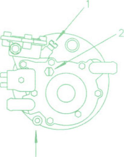
Verify that the sensitivity adjustment screw (Fig. 3, pos.1) be completely turned clockwise;
Adjust the engine idle level by means of the corresponding screw only (Fig. 3, pos. 2)
Vehicle with carburetted engine
Unscrew (open) completely the maximum flow capacity adjustment element (this is normally on the gas pipe from the Pressure Reducer to the Mixer), then accelerate to about 3000 rpm;
Screw in (close) this adjustment until a reduction of the engine speed is noted:
Unscrew (open) again this adjustment until the previous engine speed of 3000 rpm is reached;
Decelerate to the idle level and, if necessary, correct again by means of the idle adjusting screw (Fig. 3, pos. 2); Vehicles with injected engine and Lambda sensor
- In
case
of vehicle equipped with injected engine and
cathalitic
converter follow the adjustment procedure defined
by
the Supplier of the Lambda electronic control unit.
(final verifications: all vehicles types)
Perform a road testing of the vehicle, verifying the correct operation of the Reducer:
If during the test anomalies of the engine running in case of sharp brakings or turns are noticed, adjust the carbura-tion by means of the 2 adjusting screws of the Reducer, as follows:
Screw in (close) the idle adjusting screw (Fig. 3, pos.2) to reduce the engine speed by 100/150 rpm;
Set the optimum idle level by means of the sensitivity adjustment screw (Fig, 3, pos.1)
MAINTENANCE
At least once in the year, or indicatively every 20.000 Km (depending from the quality of LPG used) it is suggested to drain the oil deposited inside the Reducer, by removing the screw (Fig. 3, pos. 3), closing again at the end. This operation shall be done when the engine is warm. After 50.000 km or after 3 years the filter unit has to be rnan-tained with original components. The maintenance shall be more frequent if the Lpg quality is low (dirty).

Wyszukiwarka
Podobne podstrony:
PANsound manual
als manual RZ5IUSXZX237ENPGWFIN Nieznany
hplj 5p 6p service manual vhnlwmi5rxab6ao6bivsrdhllvztpnnomgxi2ma vhnlwmi5rxab6ao6bivsrdhllvztpnnomg
BSAVA Manual of Rabbit Surgery Dentistry and Imaging
Okidata Okipage 14e Parts Manual
Bmw 01 94 Business Mid Radio Owners Manual
Manual Acer TravelMate 2430 US EN
manual mechanika 2 2 id 279133 Nieznany
4 Steyr Operation and Maintenance Manual 8th edition Feb 08
Oberheim Prommer Service Manual
cas test platform user manual
Kyocera FS 1010 Parts Manual
juki DDL 5550 DDL 8500 DDL 8700 manual
Forex Online Manual For Successful Trading
ManualHandlingStandingAssessment
Brother PT 2450 Parts Manual
Jabra CLIPPER Manual PL 10311 (1)
ManualHandlingSittingAssessment