pll do Veronica

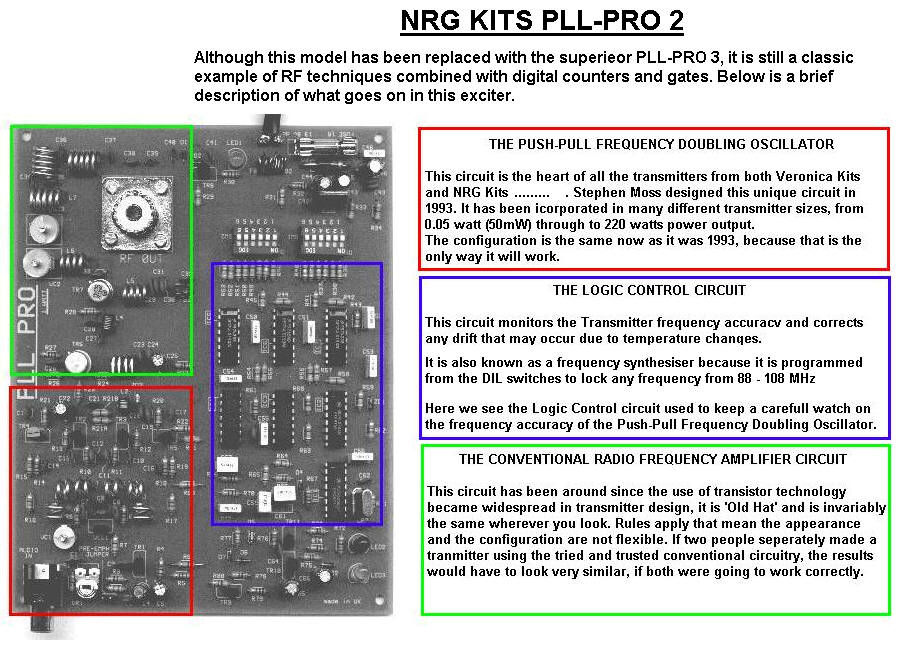
Although this model has been replaced with the superieor PLL-PRO 3, it is still a classic example of RF techniques combined with digital counters and gates. Below is a brief description of what goes on in this exciter.

THE PUSH-PULL FREOUENCY DOUBLING OSCILLATOR
This Circuit is the heart of ali the transmitters from both Veronica Kits
and NRG Kits..........Stephen Moss designed this unique Circuit in
1993. It has been icorporated in many different transmitter sizes, from 0.05 watt (50mW) through to 220 watts power output.
The configuration is the same now as it was 1993, because that is the only way it will work.
THE LOGIC CONTROL CIRCUIT
This Circuit monitors the Transmitter freguency accuracv and corrects any drift that may occur due to temperaturę chanqes.
It is also known as a frequency synthesiser because it is programmed from the DIL switches to lock any frequency from 88 -108 MHz
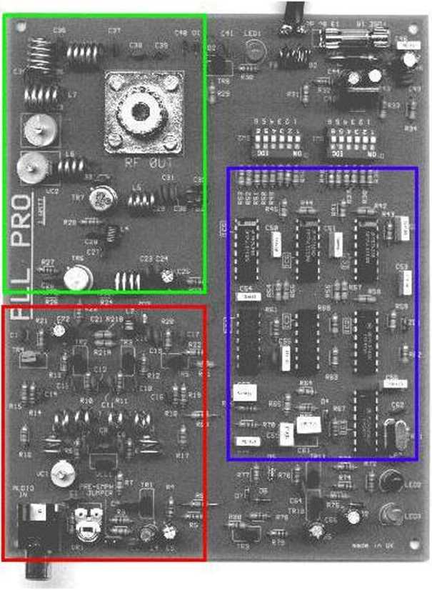
Here we see the Logic Control Circuit used to keep a carefull watch on the freguency accuracy of the Push-Pull Freguency Doubling Oscillator.
THE CONVENTIONAL RADIO FREOUENCY AMPLIFIER CIRCUIT
This Circuit has been around sińce the use of transistor technology became widespread in transmitter design, it is ’Old Hat’ and is invariably the same wherever you look. Rules apply that mean the appearance and the configuration are notf1exible. Iftwo people seperately madę a tranmitter using the tried and trusted conventional circuitry, the results would have to look very similar, if both were going to work correctly.
_
Wyszukiwarka
Podobne podstrony:
pll do Veronica NRG KITS PLL-PRO 2Although this model has been replaced with the superieor PLL-PRO 3
scan0017 3 4 MICHAEL COX with extensive recycling, some impurities do build up in the process stream
T svyml projekty z tohoto jlźnfho cfpu Afrlky expandovall do celć ho sv£ta. Pro archltekty było zśsa
Zpracovani, teżba a prodej drcenych a miętych vapencu pro oblast zemedelstvi (do krmnych smesi, na h
Zpracovani, teżba a prodej drcenych a miętych vapencu pro oblast zemedelstvl (do krmnych smesi, na h
Bez nazwy 3 (7) zostawili mi coś do jc-dzenia?” — pomyślała przed pro- fie.T. mieszkania i nacisnęła
Wraca Pio do awcRo domku. a lu pcroi pro/.<-ri cwfca Proriamk. —
skanowanie0063 (6) Grammar practice exercises do not necessarily have to be written ones, and should
skanuj0008 (340) 8. 9. 10.11.12. 13. 14. Mary is a very_student, never failing to do her homework. D
skanuj0043 2 Match the questions with the answers. ^ Write questions to the answer
skanuj0046(1) g Match the sentences with the pictures Dopasuj zdania do ilustracji. &nbs
If you have a problem with something you’ve bought, or with the semce in a shop, do you usually comp
GEOGRAPHICAL NAMES True or false? 1 With the names of continents we do not use an
pack, you will not be able to do some of the laboratory activities and therefore it is important you
więcej podobnych podstron