1 (161)

Strona 22 z 46
Spy Circuits

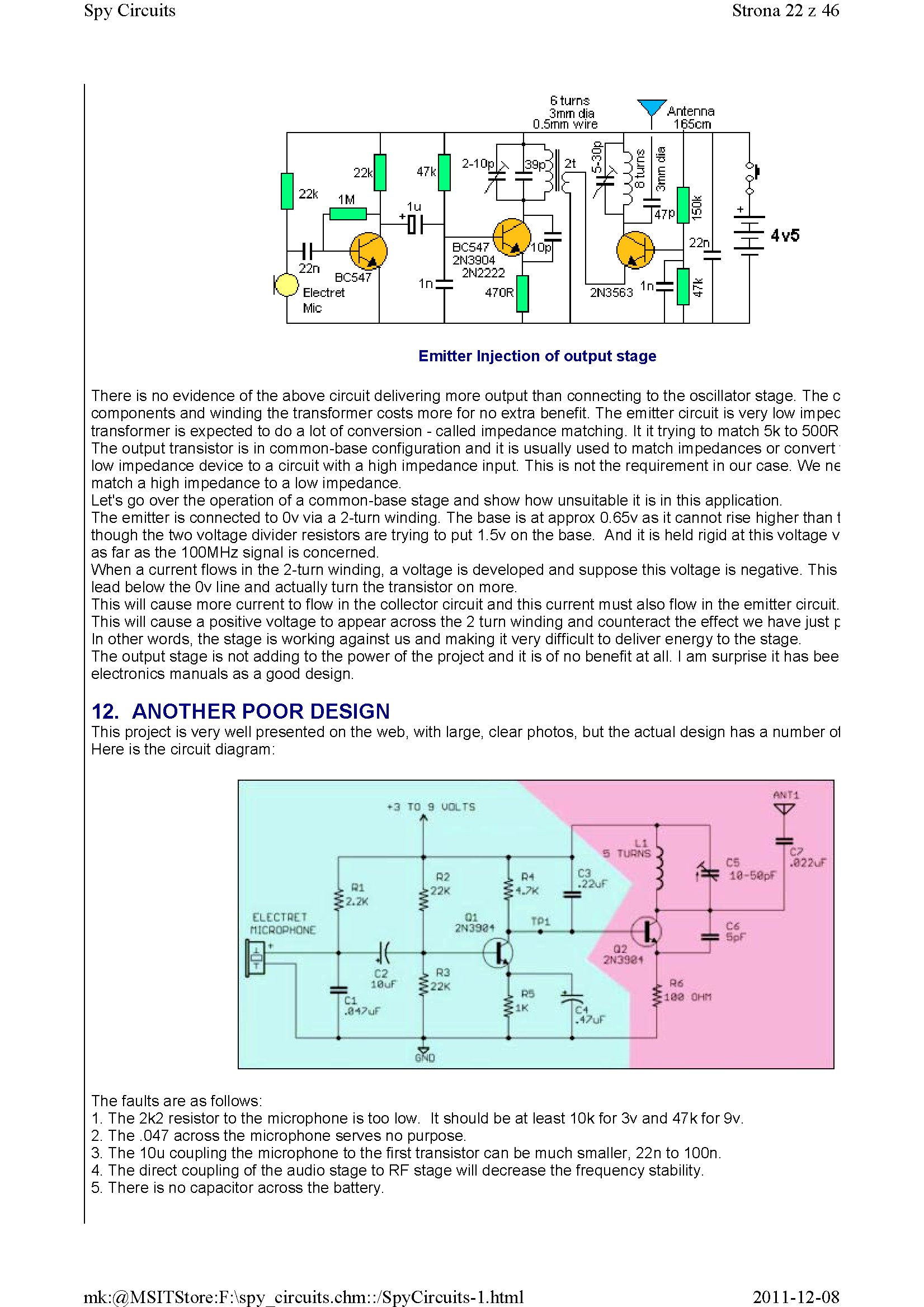
There is no evidence of the above Circuit de!ivering morę output than connecting to the oscillator stage. The c components and winding the transformer costs morę for no extra benefit. The emitter Circuit is very Iow impec transformer is expected to do a lot of conversion - called impedance matching. It it trying to match 5k to 500R The output transistor is in common-base configuration and it is usually used to match impedances or convert Iow impedance device to a Circuit with a high impedance input. This is not the requirement in our case. We ne match a high impedance to a Iow impedance.
Let's go over the operation of a common-base stage and show how unsuitable it is in this application.
The emitter is connected to 0v via a 2-turn winding. The base is at approx 0.65v as it cannot rise higher than t though the two voltage divider resistors are trying to put 1.5v on the base. And it is held rigid at this voltage v as far as the 100MHz signal is concerned.
When a current flows in the 2-turn winding, a voltage is developed and suppose this voltage is negative. This lead below the 0v linę and actually tum the transistor on morę.
This will cause morę current to flow in the collector Circuit and this current must also flow in the emitter Circuit. This will cause a positive voltage to appear across the 2 tum winding and counteract the effect we have just p In other words, the stage is working against us and making it very difficult to deliver energy to the stage.
The output stage is not adding to the power of the project and it is of no benefit at all. I am surprise it has bee electronics manuals as a good design.
12. ANOTHERPOOR DESIGN
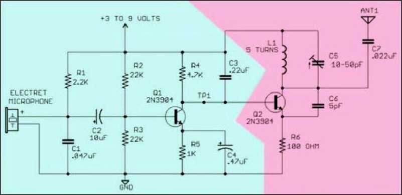
This project is very well presented on the web, with large, elear photos, but the actual design has a number ol Here isthe Circuit diagram:

The faults are as follows:
1. The 2k2 resistor to the microphone is too Iow. It should be at least 10k for 3v and 47k for 9v.
2. The .047 across the microphone serves no purpose.
3. The 10u coupling the microphone to the first transistor can be much smaller, 22n to 100n.
4. The direct coupling of the audio stage to RF stage will decrease the frequency stability.
5. There is no capacitor across the battery.
2011-12-08
mk:@MSITStore:F:\spy circuits.chm::/SpyCircuits-l.html
Wyszukiwarka
Podobne podstrony:
1 (151) Strona 12 z 46 Spy Circuits - 5v for maximum output. The Voyager has been copied by many kit
1 (149) Strona 10 z 46 Spy Circuits2 TRANSISTOR CIRCUITS The next progressive step is to add a trans
1 (167) Strona 28 z 46 Spy Circuits But it is often quite inconvenient to use a long antenna, so her
1 (173) Strona 34 z 46 Spy CircuitsTELEPHONE BUG Look at the coil. A floppy coil like this is totall
1 (181) Strona 42 z 46 Spy Circuits coil. Ali the othertransmitters have sufficient output to detect
1 (150) Strona 11 z 46 Spy Circuits magnetic field" and this occurs when the coil collapses and
1 (154) Strona 15 z 46 Spy Circuits To get good audio ampiification, and a stable oscillator and the
1 (157) Strona 18 z 46 Spy Circuits4. DIFFERENT COUPLING We have already mentioned the fact that a c
1 (159) Strona 20 z 46 Spy Circuits8. CLASS "C" OUTPUT The following Circuit uses no biasi
1 (160) Strona 21 z 46 Spy Circuits with frequencies around 100MHz. It seems the designer had diffic
1 (162) Strona 23 z 46 Spy Circuits When you fix these faults you will see how much improvement you
1 (163) Strona 24 z 46 Spy Circuits This covers all the possible combinations for the greatest outpu
1 (166) Strona 27 z 46 Spy Circuits corwert a high-voltage at low-current into a low-voltage at high
1 (168) Strona 29 z 46 Spy Circuits A Circuit diagram does not show the screening necessary to keep
1 (169) Strona 30 z 46 Spy Circuits You can learn a lot about designing a Circuit by looking at faul
1 (170) Strona 31 z 46 Spy Circuits This means a certain amount of the energy delivered by the 4p7 w
1 (172) Strona 33 z 46 Spy Circuits AER I AL 1. You don t need 10u and 100u electr
1 (176) Strona 37 z 46 Spy Circuits junction of the DC amplifier transistor only allowing ,6v to app
1 (178) Strona 39 z 46 Spy Circuits We needrYt say any morę about construction as you will obvious!y
więcej podobnych podstron