1 (176)

Strona 37 z 46
Spy Circuits
junction of the DC amplifier transistor only allowing ,6v to appear across them.
When a signal is passed into the diodę pair, the negative excursions reduce the voltage across them and this the DC amplifier transistor and thus the needie on the meter drops. It requires about 300mV signal to start the a gain of about 12 on the RF transistor, we need about 30 millivoits developed on the antenna Circuit to start t process.
This makes the Field Strength Meter only sensitive to nearby signals and prevents weaker signals from upset The 10k pot connected to one end of the voltmeter sets the full-scale deflection for a 0-10v rangę on the multi The Circuit consumes about 3.5mA and with a lighter battery (SOmAHr cells) the Circuit will operate for morę tl switch is provided to conserve the battery when not required and the board attaches to any multimeter via lea that have been bent to suit the banana sockets on the meter.
Any old meter will do and it can have a sensitivity from 1 k ohms per volt to 50k ohms per volt. The rangę we i prototype is 10v DC on a 30k ohms per volt meter however 12v, 15v or even 25v scalę will be ok and the 25v means the needie will not deflect as much, for the same RF detected.
You can even use an old, broken, multimeter providing the movement is not damaged. We have about 5 of th meters, one for each worker, as everyone needs one to peak the devices we are making We tumed 5 broken multimeters into active service. It’s one good way of using damaged equipment. It's arna; can blow up things, with the ohms rangę not working and the milliamp rangę burnt out.
I remember one firm had the same problem. They madę all the staff spend every Friday afternoon repairing tl but with the tight economics of today, we couldn't afford the luxury of providing half a day's holiday like this ez

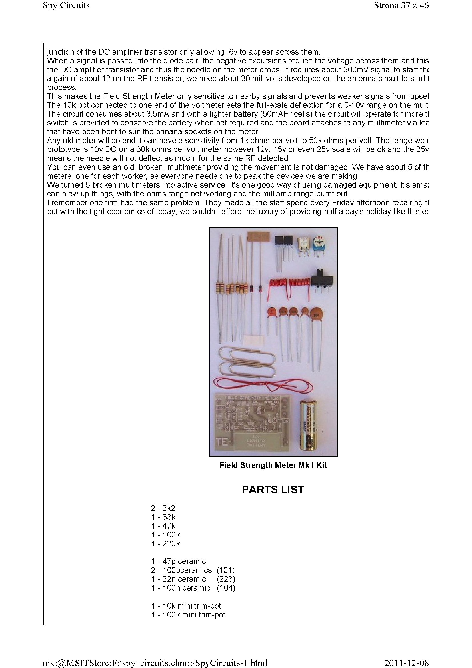
PARTS LIST
2 - 2k2 1 - 33k 1 - 47k 1 -100k 1 -220k
1 - 47p ceramic
2 - 100pceramics (101) 1 - 22n ceramic (223) 1 - 100n ceramic (104)
1-1 Ok mini trim-pot 1 - 100k mini trim-pot
2011-12-08
mk:@MSITStore:F:\spy circuits.chm::/SpyCircuits-l.html
Wyszukiwarka
Podobne podstrony:
1 (181) Strona 42 z 46 Spy Circuits coil. Ali the othertransmitters have sufficient output to detect
1 (159) Strona 20 z 46 Spy Circuits8. CLASS "C" OUTPUT The following Circuit uses no biasi
1 (161) Strona 22 z 46 Spy Circuits There is no evidence of the above Circuit de!ivering morę output
1 (170) Strona 31 z 46 Spy Circuits This means a certain amount of the energy delivered by the 4p7 w
1 (179) Strona 40 z 46 Spy CircuitsEXPERIMENTING Take the Voyager project and connect 30cm of tinned
1 (182) Strona 43 z 46 Spy Circuits lt s a bit like hundreds of people trying to push a person on a
1 (149) Strona 10 z 46 Spy Circuits2 TRANSISTOR CIRCUITS The next progressive step is to add a trans
1 (150) Strona 11 z 46 Spy Circuits magnetic field" and this occurs when the coil collapses and
1 (151) Strona 12 z 46 Spy Circuits - 5v for maximum output. The Voyager has been copied by many kit
1 (154) Strona 15 z 46 Spy Circuits To get good audio ampiification, and a stable oscillator and the
1 (157) Strona 18 z 46 Spy Circuits4. DIFFERENT COUPLING We have already mentioned the fact that a c
1 (160) Strona 21 z 46 Spy Circuits with frequencies around 100MHz. It seems the designer had diffic
1 (162) Strona 23 z 46 Spy Circuits When you fix these faults you will see how much improvement you
1 (163) Strona 24 z 46 Spy Circuits This covers all the possible combinations for the greatest outpu
1 (166) Strona 27 z 46 Spy Circuits corwert a high-voltage at low-current into a low-voltage at high
1 (167) Strona 28 z 46 Spy Circuits But it is often quite inconvenient to use a long antenna, so her
1 (168) Strona 29 z 46 Spy Circuits A Circuit diagram does not show the screening necessary to keep
1 (169) Strona 30 z 46 Spy Circuits You can learn a lot about designing a Circuit by looking at faul
1 (172) Strona 33 z 46 Spy Circuits AER I AL 1. You don t need 10u and 100u electr
więcej podobnych podstron