1 (182)

Strona 43 z 46
Spy Circuits
lt's a bit like hundreds of people trying to push a person on a swing - most of them will get in the way of each a signal at 150MHz will try to push the swing when it is coming towards the pusher and the energy will be app time.
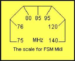
Ali the other signals will be pushing at the wrong time too and the only signal that pushes at exactly the correc one marked on the scalę. Its energy will not be lost in the tuned Circuit but appear on the output. This signal is stage via a 47p capacitor for amplification.
The RF stage is able to amplify signals in the 100MHz rangę as we have used a high frequency transistor ant appears at the collector.
Two further stages of amplification are needed to increase the signal so that it is large enough to be fed into £ biased in a standard self-bias configuration while G3 is biased in an unusual way. It is biased ON so that sma input do not appear at the collector. This means the noise generated by the first two stages is prevented from diodę pump. Only signals above a certain threshold on the base of Q3 appear on the collector. This signal is i diodę and fed into a 100n reservoir capacitor.

The other diodę (between the 1 n capacitor and negative raił) removes the negative portions of the waveform . the 1n capacitor so that it can supply positive pulses for the charging process.
The first transistor in the staircase (Q4) starts to turn on when ,6v is present on the reservoir capacitor. As the to ,65v the LED connected to the collector of 04 gets brighter and brighter. Due to the slight voitage drop acrc bias resistor, the voltage on the reservoir capacitor needs to be slightly higher than ,65v and once the first tra staircase is turned on fully, the next transistor (Q5) will begin to turn on as the voltage on the reservoir capaci slightly above 1.3v (,65v + ,65v).
This process continues with the middle LED getting brighter and brighter until it is fully turned on.
As the voltage on the reservoir capacitor increases, the top LED will come ON and illuminate fully.
The 3 LEDs will give plenty of rangę as you can read values such as a LED fully turned on or partialiy turned It is important to know that the lower transistor (G4), turns on FIRST and as the voltage on the reservoir capa then Q6 turns on. Without this, you will not be able to understand how the Circuit works.

2011-12-08
mk:@MSITStore:F:\spy circuits.chm::/SpyCircuits-l.html
Wyszukiwarka
Podobne podstrony:
1 (181) Strona 42 z 46 Spy Circuits coil. Ali the othertransmitters have sufficient output to detect
1 (161) Strona 22 z 46 Spy Circuits There is no evidence of the above Circuit de!ivering morę output
1 (170) Strona 31 z 46 Spy Circuits This means a certain amount of the energy delivered by the 4p7 w
1 (149) Strona 10 z 46 Spy Circuits2 TRANSISTOR CIRCUITS The next progressive step is to add a trans
1 (150) Strona 11 z 46 Spy Circuits magnetic field" and this occurs when the coil collapses and
1 (151) Strona 12 z 46 Spy Circuits - 5v for maximum output. The Voyager has been copied by many kit
1 (154) Strona 15 z 46 Spy Circuits To get good audio ampiification, and a stable oscillator and the
1 (157) Strona 18 z 46 Spy Circuits4. DIFFERENT COUPLING We have already mentioned the fact that a c
1 (159) Strona 20 z 46 Spy Circuits8. CLASS "C" OUTPUT The following Circuit uses no biasi
1 (160) Strona 21 z 46 Spy Circuits with frequencies around 100MHz. It seems the designer had diffic
1 (162) Strona 23 z 46 Spy Circuits When you fix these faults you will see how much improvement you
1 (163) Strona 24 z 46 Spy Circuits This covers all the possible combinations for the greatest outpu
1 (166) Strona 27 z 46 Spy Circuits corwert a high-voltage at low-current into a low-voltage at high
1 (167) Strona 28 z 46 Spy Circuits But it is often quite inconvenient to use a long antenna, so her
1 (168) Strona 29 z 46 Spy Circuits A Circuit diagram does not show the screening necessary to keep
1 (169) Strona 30 z 46 Spy Circuits You can learn a lot about designing a Circuit by looking at faul
1 (172) Strona 33 z 46 Spy Circuits AER I AL 1. You don t need 10u and 100u electr
1 (173) Strona 34 z 46 Spy CircuitsTELEPHONE BUG Look at the coil. A floppy coil like this is totall
1 (176) Strona 37 z 46 Spy Circuits junction of the DC amplifier transistor only allowing ,6v to app
więcej podobnych podstron