1 (175)
Spy Circuits
Strona 36 z 46
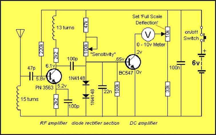
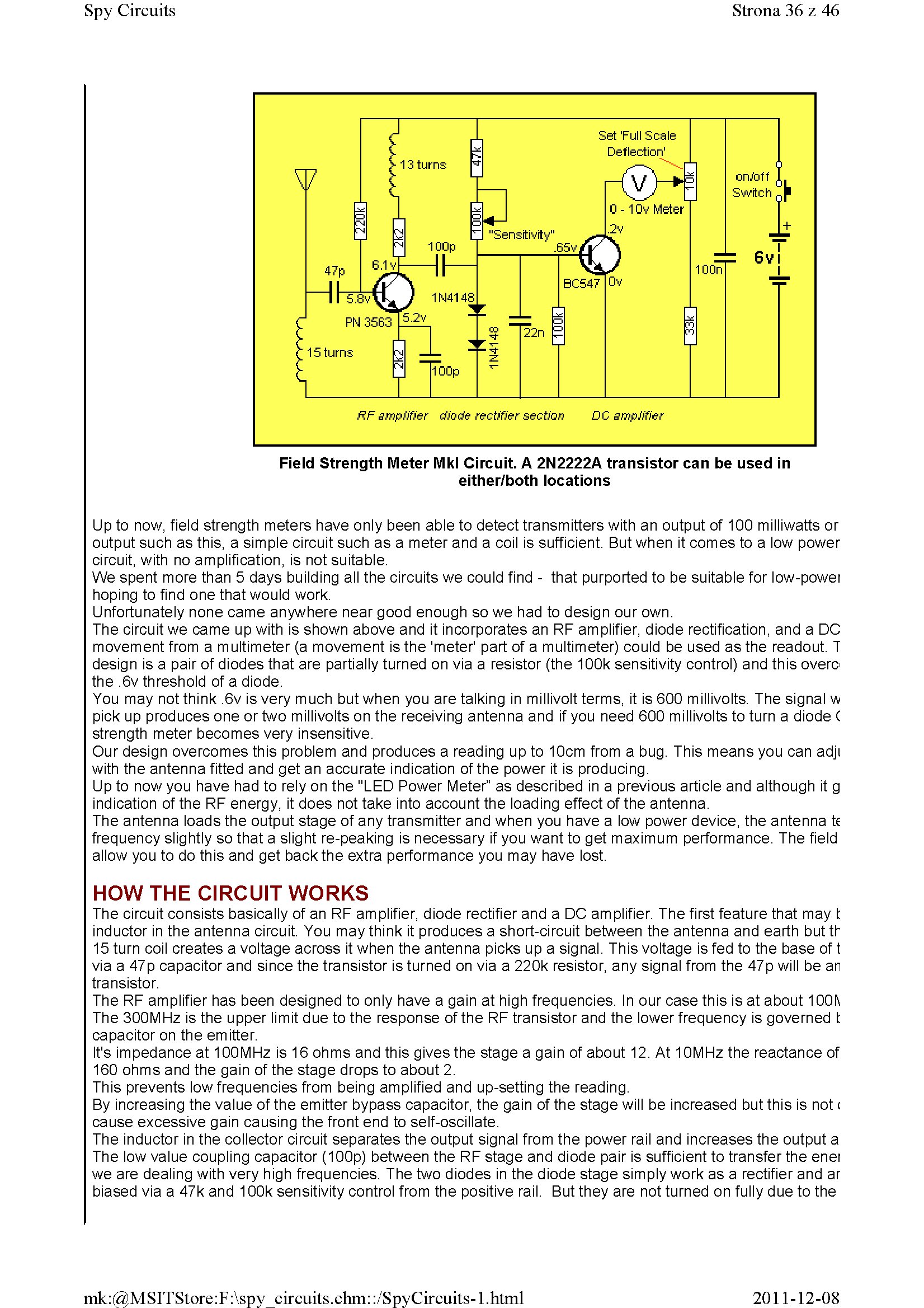
Field Strength Meter Mkl Circuit. A 2N2222A transistor can be used in
either/both locations
Up to now, field strength meters have only been able to detect transmitters with an output of 100 milliwatts or output such as this, a simple Circuit such as a meter and a coil is sufficient. But when it comes to a Iow power Circuit, with no amplification, is not suitable.
We spent morę than 5 days building all the circuits we could find - that purported to be suitable for low-powei hoping to find one that would work.
Unfortunately nonę came anywhere near good enough so we had to design our own.
The Circuit we came up with is shown above and it incorporates an RF amplifier, diodę rectification, and a DC movement from a multimeter (a movement isthe 'meter' part of a multimeter) could be used as the readout. T design is a pair of diodes that are partially turned on via a resistor (the 100k sensitivity control) and this overo the ,6v threshold of a diodę.
You may not think ,6v is very much but when you are talking in millivolt terms, it is 600 millivolts. The signal w pick up produces one or two millivolts on the receiving antenna and if you need 600 millivolts to tum a diodę C strength meter becomes very insensitive.
Our design overcomes this problem and produces a reading up to 10cm from a bug. This means you can adji with the antenna fitted and get an accurate indication of the power it is producing.
Up to now you have had to rely on the "LED Power Meter” as described in a previous article and although it g indication of the RF energy, it does not take into account the loading effect of the antenna.
The antenna loads the output stage of any transmitter and when you have a Iow power device, the antenna te frequency slightly so that a slight re-peaking is necessary if you want to get maximum performance. The field allow you to do this and get backthe extra performance you may have lost.
HOW THE CIRCUIT WORKS
The Circuit consists basically of an RF amplifier, diodę rectifier and a DC amplifier. The first feature that may fc inductor in the antenna Circuit. You may think it produces a short-circuit between the antenna and earth but th 15 tum coil creates a voltage across it when the antenna picks up a signal. This voltage is fed to the base of t via a 47p capacitor and sińce the transistor is turned on via a 220k resistor, any signal from the 47p will be an transistor.
The RF amplifier has been designed to only have a gain at high frequencies. In our case this is at about 100l\ The 300MHz is the upper limit due to the response of the RF transistor and the lower frequency is governed l: capacitor on the emitter.
It’s impedance at 100 MHz is 16 ohms and this givesthe stage a gain of about 12. At 10M Hz the reactance of 160 ohms and the gain of the stage drops to about 2.
This prevents Iow frequencies from being amplified and up-setting the reading.
By increasing the value of the emitter bypass capacitor, the gain of the stage will be increased but this is not c cause excessive gain causing the front end to self-oscillate.
The inductor in the collector Circuit separates the output signal from the power raił and increases the output a The Iow value coupling capacitor (100p) between the RF stage and diodę pair is sufficient to transfer the enei we are dealing with very high frequencies. The two diodes in the diodę stage simply work as a rectifier and ar biased via a 47k and 10Ok sensitivity control from the positive raił. But they are not turned on fully due to the
2011-12-08
mk:@MSITStore:F:\spy circuits.chm::/SpyCircuits-l.html
Wyszukiwarka
Podobne podstrony:
1 (174) Spy Circuits Strona 35 z 46 A close-up of the Field Strength Meter Mkl connected to a multim
1 (183) Spy CircuitsStrona 44 z 46 Field Strength Meter Mk II KitPARTS LIST 1-100R 1 -330R 1 -4
1 (180) Strona 41 z 46 Spy Circuits This project has 3 features. 1. It s a Field S
1 (185) Strona 46 z 46 Spy Circuits 100MHz rangę. If you are building our transmitters, a Field Stre
Schemat Miernika poziomu sygnału WiFi 2 4Ghz Simple Field Strength Meter 2.4 GHz 1/4 wave antenna 2
k1 thumbnail2 Enter new /, Add Custom Field Custcm fields can be used tc add extra metadata tc a
1 (150) Strona 11 z 46 Spy Circuits magnetic field" and this occurs when the coil collapses and
1 (181) Strona 42 z 46 Spy Circuits coil. Ali the othertransmitters have sufficient output to detect
1 (141) Strona 2 z 46 Spy Circuits These circuits are very powerful, in that they are very hard to d
1 (142) Strona 3 z 46 Spy Circuits pulse is amplified by the transistor and the Circuit is kept acti
1 (143) Spy Circuits Strona 4 z 46 illuminate. So far we have seen an unstable Circuit in action. Pi
1 (146) Spy Circuits Strona 7 z 46 The finished bug with "studs" for the battery and a cut
1 (147) Strona 8 z 46 Spy CircuitsAN IMPROVED DESIGN This design uses a "sług tuned coil"
1 (148) Spy Circuits Strona 9 z 46 Antenna The emitter resistor is too Iow Inductor is 6 tums of wir
1 (149) Strona 10 z 46 Spy Circuits2 TRANSISTOR CIRCUITS The next progressive step is to add a trans
1 (151) Strona 12 z 46 Spy Circuits - 5v for maximum output. The Voyager has been copied by many kit
1 (152) Spy Circuits Strona 13 z 46 See the layout below: Faults with this Circuit: 1. Load resistor
więcej podobnych podstron