1 (183)
Field Strength Meter Mk II Kit
PARTS LIST
1-100R 1 -330R 1 -470R 1 -1k
4 - 4k7 1 - 10k 1 - 47k
2 - 47p ceramics 2 - 100p ceramics 2 - 1n ceramics
1 - 100n mono-block capacitor 1 - 4 - 40p air trimmer
1 - 47u 16v PC mount electroiytic
2 - 1N 4148 diodes
5 - BC 547 transistors 1 - PN 3563 transistor 4 - 3mm red LEDs
1 - SPDT slide switch
1 - paper clip for pointer on trimmer 1 - 5cm enameiled wire for antenna
1 - 10cm tinned wire for batteries
2 - 3v lithium cells
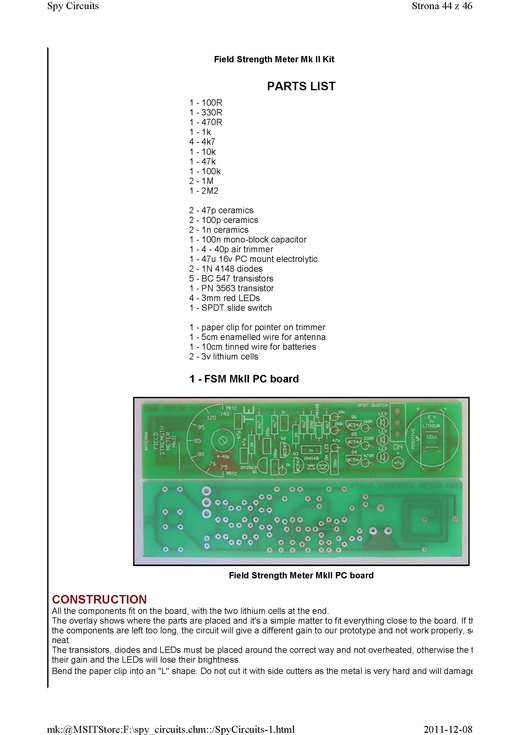
1 - FSM Mkll PC board
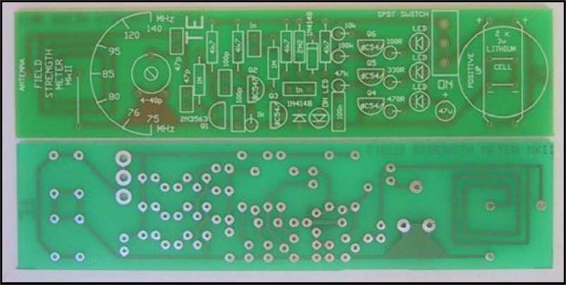
Field Strength Meter Mkll PC board
CONSTRUCTION
Ail the components fit on the board, with the two lithium cells at the end.
The overlay shows where the parts are placed and it's a simple matter to fit everything close to the board. If tl the components are left too long, the Circuit will give a different gain to our prototype and not work properly, si neat.
The transistors, diodes and LEDs must be placed around the correct way and not overheated, otherwise the t their gain and the LEDs will lose their brightness.
Bend the paper clip into an "L" shape. Do not cut it with side cutters as the metal is very hard and will damag?
2011-12-08
mk:@MSITStore:F:\spy circuits.chm::/SpyCircuits-l.html
Wyszukiwarka
Podobne podstrony:
1 (175) Spy Circuits Strona 36 z 46 Field Strength Meter Mkl Circuit. A 2N2222A transistor can be us
1 (174) Spy Circuits Strona 35 z 46 A close-up of the Field Strength Meter Mkl connected to a multim
1 (180) Strona 41 z 46 Spy Circuits This project has 3 features. 1. It s a Field S
1 (185) Strona 46 z 46 Spy Circuits 100MHz rangę. If you are building our transmitters, a Field Stre
Schemat Miernika poziomu sygnału WiFi 2 4Ghz Simple Field Strength Meter 2.4 GHz 1/4 wave antenna 2
1 (143) Spy Circuits Strona 4 z 46 illuminate. So far we have seen an unstable Circuit in action. Pi
1 (146) Spy Circuits Strona 7 z 46 The finished bug with "studs" for the battery and a cut
1 (148) Spy Circuits Strona 9 z 46 Antenna The emitter resistor is too Iow Inductor is 6 tums of wir
1 (150) Strona 11 z 46 Spy Circuits magnetic field" and this occurs when the coil collapses and
1 (181) Strona 42 z 46 Spy Circuits coil. Ali the othertransmitters have sufficient output to detect
1 (141) Strona 2 z 46 Spy Circuits These circuits are very powerful, in that they are very hard to d
1 (142) Strona 3 z 46 Spy Circuits pulse is amplified by the transistor and the Circuit is kept acti
1 (147) Strona 8 z 46 Spy CircuitsAN IMPROVED DESIGN This design uses a "sług tuned coil"
1 (149) Strona 10 z 46 Spy Circuits2 TRANSISTOR CIRCUITS The next progressive step is to add a trans
1 (151) Strona 12 z 46 Spy Circuits - 5v for maximum output. The Voyager has been copied by many kit
1 (152) Spy Circuits Strona 13 z 46 See the layout below: Faults with this Circuit: 1. Load resistor
1 (154) Strona 15 z 46 Spy Circuits To get good audio ampiification, and a stable oscillator and the
1 (157) Strona 18 z 46 Spy Circuits4. DIFFERENT COUPLING We have already mentioned the fact that a c
więcej podobnych podstron