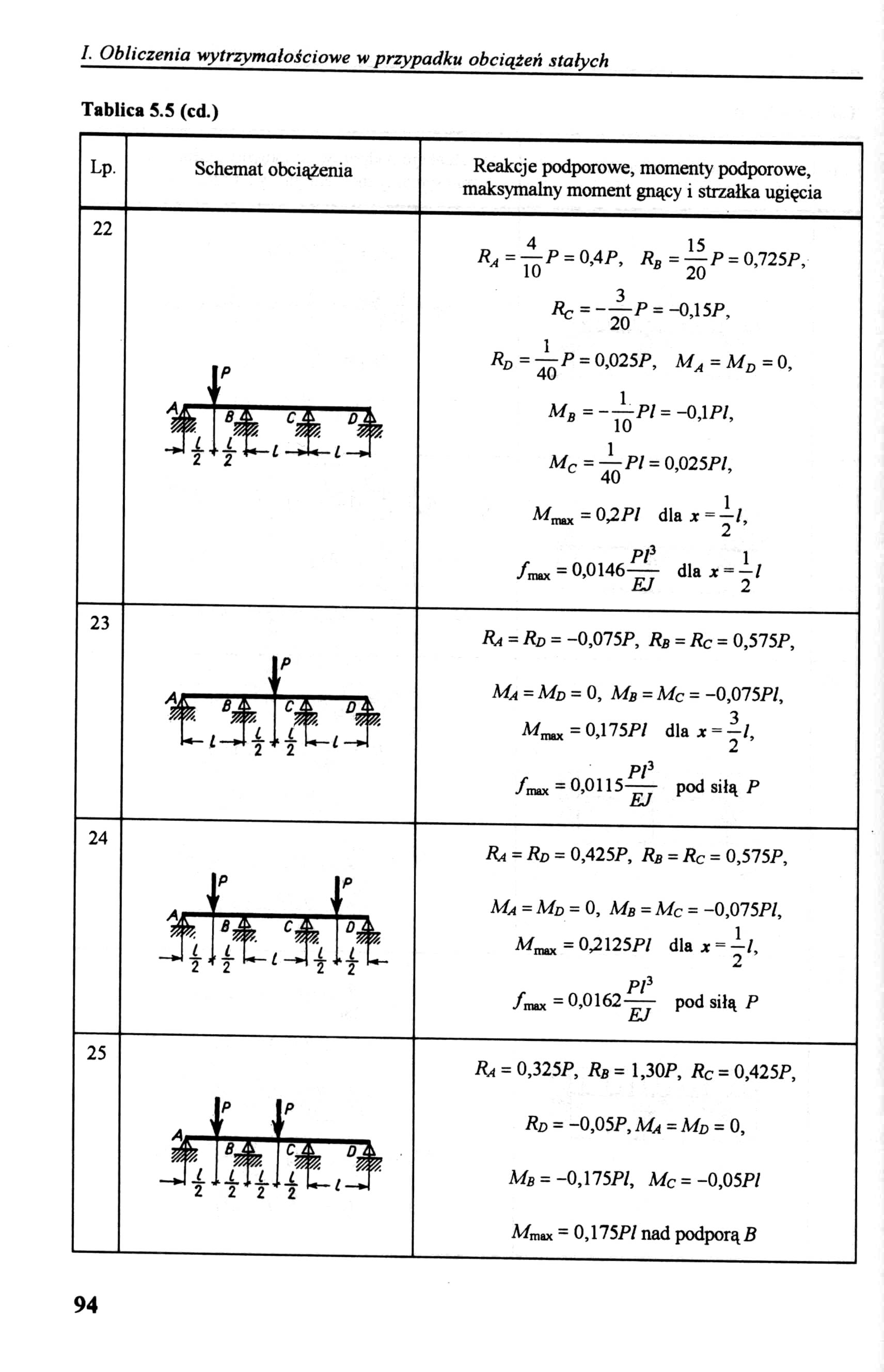
IMG00094

I. Obliczenia wytrzymałościowe w przypadku obciążeń stałych
Tablica S.S (cd.)
Lp.
Schemat obciążenia
Reakcje podporowe, momenty podporowe, maksymalny moment gnący i strzałka ugięcia
22
R.=—P = 0,4P, Rb = —P = 0,725P, ^ 10 B 20
Pc = -—P = -0,15P, v 20
PD=^P = 0,025P, Ma = Md = 0,
Mg =--—Pl= -0,1 P/,
B 10
Mc=—P/ = 0,025P/, c 40
= 02.Pl dla x ~ ~l,
PI3 1
7™= 0,0146- dla x = —l
Jm*x £/ 2
23
Ra = Rd = -0,075P, RB = Rc = 0,575P,
|
1 |
p ’ |
|
fe BĄ, |
cl 0 A |
Ma=Md = 0, Mb=Mc= -0.075P/, M.^ = 0,175/^/ dla* = |/,
P/3
/max = 0,0115— pod siłą P EJ
24
Ra=Rd = 0,425P, Rb = Rc = 0,575P,
MA = MD = 0, Me = MC = -0,075P/, Wmax=0^125P/ dla x = -^7, P/3
/rmx = 0,0162 — pod siłą P
25
|
p |
p | |||
|
4 |
> |
r |
i |
' |
|
i |
b |
c. | ||
|
>łJ |
rłJ |
2 |

P< = 0,325P, PB = 1,30P, Pc = 0.425P, Pd = -0.05P, MA = MD = 0,
Mb = -0,175P/, Mc = -0,05P/ Mmax = 0,175P/ nad podporą B
94
Wyszukiwarka
Podobne podstrony:
IMG00088 I. Obliczenia wytrzymałościowe w przypadku obciążeń stałych Tablica S.4 (cd.) Lp. Schemat
IMG00096 I. Obliczenia wytrzymałościowe w przypadku obciążeń stałych Tablica 5.5 (cd.) Lp. Schemat
IMG00060 I. Obliczenia wytrzymałościowe w przypadku obciążeń stałych Tablica 4.2 (cd.) Lp. Przekrój
IMG00078 I. Obliczenia wytrzymałościowe w przypadku obciążeń stałych Tablica S.2 (cd.) Lp. Sposób
IMG00100 I. Obliczenia wytrzymałościowe w przypadku obciążeń stałych Tablica 6.1 (cd.) Lp. Schemat
IMG00110 I. Obliczenia wytrzymałościowe w przypadku obciążeń stałych Tablica 6.2 (cd.) Lp. Schemat
IMG00112 I. Obliczenia wytrzymałościowe w przypadku obciążeń stałych Tablica 7.1 (cd.) Lp. Schemat
IMG00116 1. Obliczenia wytrzymałościowe w przypadku obciążeń stałych Tablica 7.1 (cd.) Lp. Schemat
IMG00118 I. Obliczenia wytrzymałościowe w przypadku obciążeń stałych Tablica 7.2 (cd.) Lp. Schemat
IMG00124 I. Obliczenia wytrzymałościowe w przypadku obciążeń stałych Tablica 7.4 (cd.) Lp. Schemat
IMG00132 I. Obliczenia wytrzymałościowe w przypadku obciążeń stałych Tablica 9.2 (cd.) Lp. Schemat
IMG00042 I. Obliczenia wytrzymałościowe w przypadku obciążeń stałych Tablica 3.1 (cd.) I. Obliczenia
IMG00044 I. Obliczenia wytrzymałościowe w przypadku obciążeń stałych Tablica 3.2 (cd.) s=_L_ *nin
IMG00062 I. Obliczenia wytrzymałościowe w przypadku obciążeń stałych Tablica 4.2 (cd.) 62
IMG00066 I. Obliczenia wytrzymałościowe w przypadku obciążeń stałych Tablica 4.3 (cd.) I. Obliczenia
IMG00080 I. Obliczenia wytrzymałościowe w przypadku obciążeń stałych Tablica S.2 (cd.) 80
IMG00084 I. Obliczenia wytrzymałościowe w przypadku obciążeń stałych Tablica 5.4 (cd.) I. Obliczenia
IMG00086 I. Obliczenia wytrzymałościowe w przypadku obciążeń stałych Tablica 5.4 (cd.) 86
IMG00092 I. Obliczenia wytrzymałościowe w przypadku obciążeń stałych Tablica 5.5 (cd.) st 14 ’ Reakc
więcej podobnych podstron