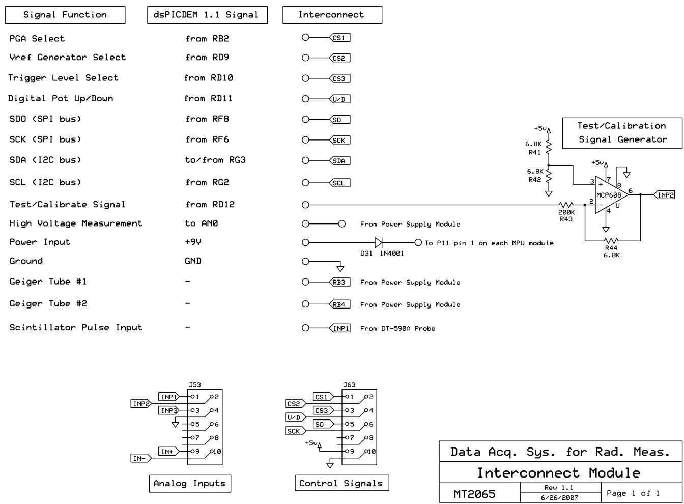
interconnect module schematic
|
Signal Function |
dsPICDEM 1.1 Signal |
Interconnect |
O-<ćsl
PGA Select
Vref Generator Select Trigger Leuel Select Digital Pot Up/Doun SDO <SPI bus)
SCK CSPI bus)
SDA < I2C bus)
SCL <I2C bus)
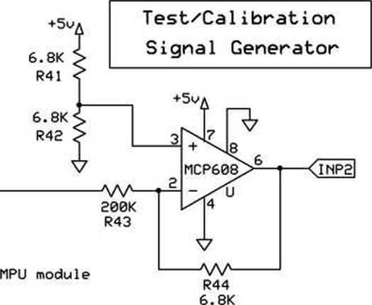
Test/Calibrate Signal High Yoltage Measurement Power Input Ground
Geiger Tubę #1 Geiger Tubę #2 Scintillator Pulse Input
from RB2 from RD9 from RD10 from RD11 from RF8 from RF6 to/from RG3 from RG2
from RD12 to AN0 +9V GND
O-1»-OTo Pil pin 1 on
D31 1N4001
|
w— |
^7 | ||
|
o— |
-<RB3 |
From |
Power Supply Module |
|
o— |
-<RB4 | |
From |
Power Supply Module |
|
O— |
-<INPl| |
From |
DT-590A Probe |
353
1INP^>
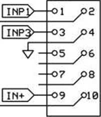
Analog Inputs
363
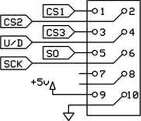
Control Signals
|
Data Acq. |
Sys. for Rad. Meas. | |
|
Interconnect Module | ||
|
MT2065 |
Rew 1.1 |
Page 1 of 1 |
|
6/26/2007 | ||
Wyszukiwarka
Podobne podstrony:
f20 13 j no j Function Modules: (55 Hits) Function modules Edit Goto Utilities System Help IW II z
const char *error; void *module; simp1e_demo_function demo_function; /* Load dynamically loaded libr
analog module schematic Yref Adjustable Yref Generator Adjustable Trigger Leuel 2 6022/^ A 1 V i
analog module schematic Yref Adjustable Yref Generator Adjustable Trigger Leuel 2 6022/^ A 1 V i
analog module schematic Yref Adjustable Yref Generator Adjustable Trigger Leuel 2 6022/^ A 1 V i
schemat produktu TWORZENIE I WYKORZYSTANIE PRODUKTU KRAJOWEGO BRUTTO W 2001 R. (ceny bieżące) GENERA
ukl 1 schemat ukladu File Clipboard Edit Options Simulation Style Signal Sinks Library >l yout I
881 911 P0881 Transmission control module (TCM) - power input signal range/performance Wiring, poor
Item Parameter Transmitter Receiver Function Transfer Signal Number 1ch Video Transmission
po - intercept (the place in which trend function crosses OY axis (vertical axis), or this is the av
schemat złącza diagnostycznego Mazdab6 GF Chassis Ground Signal GroundPiny w EIM327 J1850 Bus Ba
320tft,520tft djvu 12 Schematic Diagrams_ 12-1 DAC & I0 Part Schematic Diagram PANEL INVERTER Po
więcej podobnych podstron