3360446725


IV. OPEN-CIRCUIT NO-LOAD BACK-EMF
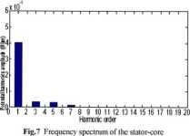
The magnetic potential distribution computed in several points of the stator core is represented by Fig.6. The frequency spectrum of magnetic potential harmonics is presented in Fig.7. Here, the dominant harmonie is the first-order harmonie, followed by odd harmonics of third, fifth and seventh orders.
III. SLOTTING EFFECT
The effect of stator slots on the no-load magnetic flux distribution is investigated. The airgap flux density always drops at stator slot openings, and this effect has a significant influence on the values of the flux and back-emf. For this reason, it is important to accurately model the airgap flux density.
The maximum flux of a certain pole can be found when a rotor-PM is located so that its centerline is coincident with that of a stator tooth. Accordingly, integrating the positive flux pulse under the tooth gives the maximum flux per pole.
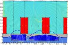
The 2-D representation of one pole of the AFBPMM machinę and the no-loadmagnetic flux distribution in the airgap are shown in Fig.8.
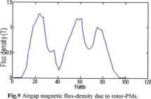
Fig.9 presents the angular variation of the airgap magnetic flux density due to the rotor-PMs.

Fig.8 No-load magnetic flu.\ distribution for one PM-rotor pole.
A comparison between FE-computed flux-related values and the experimental ones is provided. Hence, no-load tests were performed under open-circuit (gen-erator-mode) conditions using the DC machinę drive as a prime mover. The no-load test was done to evalu-ate the back-emf and to measure the armature-winding resistance and inductance.
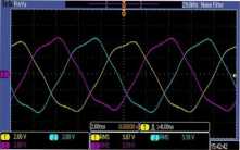
The back-emf measurements were carried out for a nominał speed of 1500 rpm. The voltage measurements are madę with the high-precision voltage oscil-loscope probe. The test results captured on the oscillo-scope are presented in Fig. 10. The open-circuit back-emfs at no-load for clockwise and counter-clockwise rotation are presented in Fig. 11 and Fig. 12, respec-tively, Both back-emf waveforms are comparatively shown in Fig. 13.
The FE-computed (using Opera 2D software) back-emf is presented in Fig. 14.
The simulated and experimental results are in good agreement, as proven by Fig. 15.

Fig. 10 Expcrnncntal open-circuit (no-load ) back-emf \vavcform captured on the oscilloscopc
V. CONCLUSIONS
A smali double-sided AFBPMM has been presented in this paper. To verify the effectiveness of the design tool, as well as to get manufacturing expertise a prototype machinę was constructed.
3/2011
POJAZDY SZYNOWE
19
Wyszukiwarka
Podobne podstrony:
BioLetyn 1/IV/2010 idziatem...Back to the lab again — impreza biotechnologów Już po raz drugi w tym
cw0032 UNITAdvertising D4® 31 Listen to the difference between /au/and /au/. /su/ as in go slow no&n
BioLetyn 1/IV/2010 idziatem...Back to the lab again — impreza biotechnologów Już po raz drugi w tym
72056 No Doubt No Doubt (Back) ®©19 Distributed by the l< A Unit ol BMG Entertamment. AJl trade
1 (152) Spy Circuits Strona 13 z 46 See the layout below: Faults with this Circuit: 1. Load resistor
BioLetyn 1/IV/2010 idziatem...Back to the lab again — impreza biotechnologów Już po raz drugi w tym
BioLetyn 1/IV/2010 idziatem...Back to the lab again — impreza biotechnologów Już po raz drugi w tym
Eq. (12). In order to obtain J„, it is necessary just to run the program, and verify the open Circui
Back STRANGERS MAY MARRY Laura had practically raised little Mandy, but she had no legał claim to&nb
Back STRANGERS MAY MARRY Laura had practically raised little Mandy, but she had no legał claim to&nb
BioLetyn 1/IV/2010 idziatem...Back to the lab again — impreza biotechnologów Już po raz drugi w tym
Hen?rn Maze Show this hen the way back to the barn.
image001 He saw the truth but coutd not charge it. No one could— except the
więcej podobnych podstron