7141313265
Start
DDC -SVC-M AN -0081 201,
Bookmarks
T9 * k©
1 California Proposition 65 V *
2 Rocker Cover
~P 2.1 Description and Operatk | 2.2 Remova! ofthe Rocker i P 2. J Cleaning and Inspection = 1 2.4 Instakation ofthe Rocke
3 Camshaft and Rocker Shal
7r
| Description and Operatk
2.2 Description and Operatk U 3.3 Removal ofthe Rocker i \ 3.4 Remo va! of the Camshai
3.5 Inspection ofthe Camsf
2.5 Instakation ofthe Camsi 'P 2.7 Instakation ofthe Rocke
4 Camshaft Housing
P 4.2 Description and Operatk J| 4.2 /?6>/77c> ra/ (?/■ Camshai
U 4.2 Inspection ofthe Camsf 4.4 Instakation ofthe Camsi
5 Camshaft Timing
1 52 Camshaft Timing Verifkć U 5.2 7/>t*w ftfe Camshafts m-
6 Gear Train and Engine Timi | 6.1 Description and Operatk
5.2 Instakation and Timing c ~P 6.3 Checking and Adjusting
7 Coolant Crossover Pipę
'P 7.2 Description and Operatk
7.2 Removaf ofthe Coofant ~P 7.3 Instakation ofthe Cooia,
8 DD15 and DD16 Water Ma 1 Description and Operatk 'P 8.2 Removaf ofthe DD15 ar ~P 2.2 Cfeaning and Inspection | 5,4 Instakation ofthe DD15
9 DD13 Exhaust Gas Recircu P P.2 Description and Operatk \ 9.2 Removaf ofthe DD13 B P 9.3 Inspection ofthe DD13 P P.4 Testing and Inspection ~P 9.5 Instakation ofthe DD13
10 Cold Boost Pipę (Charge ~P 2 5.2 Description and Operai | 25.2 Removaf of the Cold Bi P 25.2 Inspection of Cold Boo P 25.4 Instakation ofthe Cold
11 Composite Cold Boost Pi| | 22.2 Description and Operai

EPA07/10/GHG14 PD Platform Engine Systems Workshop Manuał
DD15 /

DD13
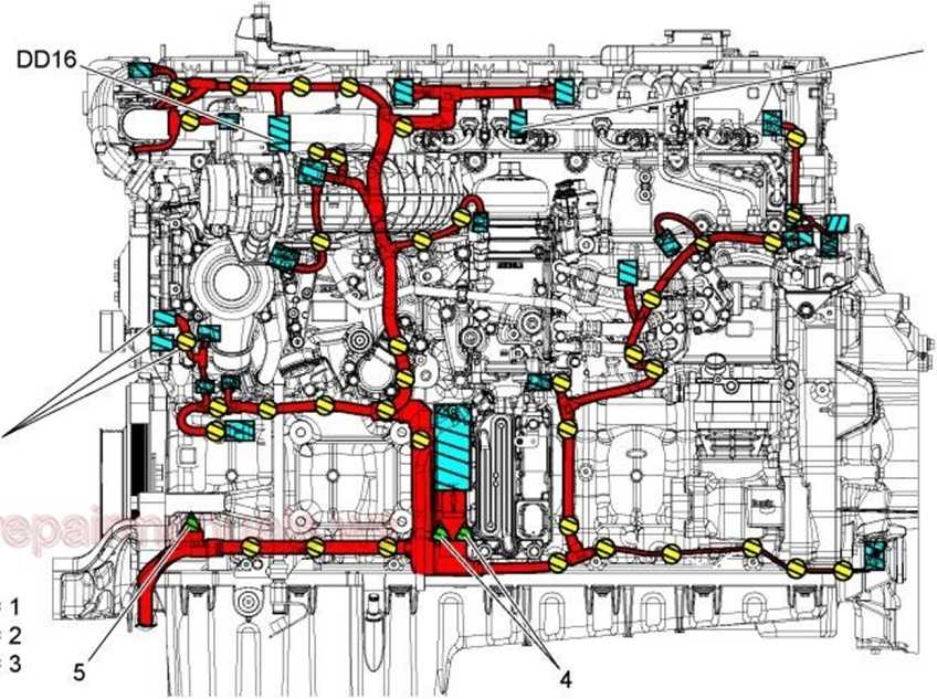
d150201
Table 41.
|
1 |
Engine wiring harness elips |
|
2 |
Connectors |
|
3 |
Bolts |
|
4 |
Motor Control Module (MCM) Connector Bolts |
|
5 |
Wiring Harness Front Left Bolt |
|
6 |
(If eguipped) Variable Speed Engine Water Pump Connectors |
10.
11.
12.
13.
Install the wiring hamess front left bolt (5) securing the left side of the engine hamess to the engine. Torque to 30 Nm (22 lb-ft) (see above graphic).
Install the MCM connector bolts (4) securing the left side ofthe engine hamess to the MCM. Torque to 25 Nm (18 lb-ft) (see above graphic).
Connect all the connectors (2) on to the left side ofthe engine (see above graphic).
Connect the batteries.
Wyszukiwarka
Podobne podstrony:
SENiTiRUIM (IMrwyfir R® IFSK&T(ŚH I NM k® n m&msmmmr® um POLITECHNIKA OPOLSKAZAPRASZAMY NA
Rys 4 $< «r ł j= rl w .Ty 0 ^1 n r~i m lU O •
4 (296) n-i~r. B /
100!74 wyznaczenia itapiężcil uupusz.Cz.an lyv«l adlczy jji ZyjąK, wTaSnDSCT materiału słabszego. k’
IMGA63 vax^ —r1-2& fS T" TS i i « i <JsJKj ■^- ■K- «A d 2 kuxJl^CJ LLjpO&i
Sm^n9 Smart Glasses Smart Fnger Smart Shf t «re> r»*rl & wnu SGPS/GPRS Baby Control Smart
wm rs,i/ n - fi Jk Aj V M ■r^ rl ^m&f w > ) * o/n:4 i -*€■ k. ~ * i ■ ^
52945 Powstrzymać oszalałą Brukselę Jesteśmy kwita Viktor Orbán "Prasa niektórych krajów cz
i i 779 ■r^rL, 1 U U V/. KS. LITEWSKIEGO. Dwudziesta ósma chorągiew miasta i
Spis treści Notatki ). W. Wojnic, .r’>rl,r.,mŻ3oAn.v:faz)in>»m u
IMAG0035 AtoswuAo »m* ___ Nr wdłWm W pi :ed*Aavwvo«ym <^eci»r«n»« pcftetim* vtdi>k» J* Hcro-w
DSC01562 (2) 1111 i R i UyUtM fmła, 12h- J
3 (2190) B t>u.<iUTe/v^ - fatop^R PALA « JNfote—)Pj?ow;r»/ rL-h4^ł#^
f28 2 Netscape - lAaa an item to me Laienaarj File Edit View Go Bookmarks Options Directory Window H
F4 5 H0E3 s Netscape • [Rotating An Image] File Edit View Go Bookmarks Options Directory Window
więcej podobnych podstron