5441337047
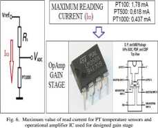
current that flows through temperaturę sensors must be lower than a threshold value, as shown in figurę 6, otherwise the sensor heating for Joule effect would degrade the accuracy in temperaturę detection.

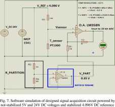
Figurę 7 shows the designed acquisition Circuit: the stabilized generator MCP1541 supplies each voltage-divider branch on which the probe PT1000 is located. The gain stage amplifies the value read on the probe (Vsensor) and shifts it in the amplified rangę 0-5V thanks to the connection of RI resistance to a voltage (Vpart) obtained by another voltage divider. This divider is also powered by the 4.096V stable voltage reference which avoids the risk of unexpected fluctuations; Vpart voltage is supplied to the terminal of R1 resistor by a further LM358N op-amp in voltage buffer configuration. With this method, the gain stage's output goes to a voltage value Vout regulated by the following law:
Vout= Ysensor (1 + R2/R1) - Ypart (R2/R1)
The maximum current Isens (see the figurę 5) supplied from IC MCP1541 is the sum of contributions from the five voltage-divider branches with PTI 000 T-sensor and from the single voltage divider branch for Vpart generation (0.35V) and so it reaches a value equal to Isens = 2.4mA. This value must be added to the absorption of the MCP1541 device for its supply, equal to O.lmA, for a total of I_VR = 2.5mA.

yoltage V_REF in order to avoid resolution toss.
The Isens current can be supplied by MCP1541 voltage reference, because the manufacturer claims that the maximum payable current is 20mA. Considering that the MC34063 DC/DC adapter has a power efficiency of 80%, it results that the total current necessary to supply MC34063 DC/DC adapter is Idc/dc= 66 mA (see figurę 5). Adding to the Idc®c the Ir current (150mA) absorbed by the actuation section, the 24V DC supply voltage must provide a total current of 220 mA, for a power dissipation of 24V*0.22A = 5.3W. Ultimately, a finał comment on the current consumption of the eight operational amplifiers (used in the sensing section) supplied between 24V and ground. The LM358 datasheet shows a maximum supply current of 2mA; each LM358 IC actually contains two op-amps in the package, so our board will need four ICs. Therefore the total supply current absorption is 8mA and this results in a total power of 24V*0.008A=192mW. Finally, the external 24V DC power supply must be able to deliver a power of 5.5 W (rounded up) in order to meet the specifications of the designed control
|
RS |
IW |
Rpt(ohm) |
Ipt(mA) |
VM(V) |
6Vstep |
R1 R2 |
Ri R4 |
|
9.21 |
40 |
842,2 |
0,408 |
0/2789428 |
| 570 | 61 |
101 990 | |
|
921 |
•39 |
846,2 |
0,408 |
0/1961624 |
0,0172146 | ||
|
| | | |||||||
|
921 |
0 |
1000 |
0,402 |
0,74581? | |||
|
921 |
: |
1003,9 |
0,402 |
0,76209 |
0/216273 |
MIMMlMYouHARUnON ■ llmY [WORST CASE for Rpt=2120.5 oku) | |
|
921 |
299 |
2112 |
0362 |
4,94812 |
OBTAINED RESOLUTION - 0.5'C | ||
|
921 |
300 |
2120,5 |
0,362 |
4,95998 |
0,01186 | ||
Fig. 8. Vout voltage valucs from conditioning Circuit (applied to ADC’s input) for differenl PT1000 values and resulling lemperalure resolution obtained with the 10 bit ADC embedded inside PIC.
IJERTY4IS04104I
1022
Wyszukiwarka
Podobne podstrony:
00321 Bb55e6b1abc36441831626f33e67239 324 McCaryille & Montgomery This also can be described pi
selenium.waitForPageToLoad("30000"); if( !selenium.isTextPresent("Must be higher than
File0006 (2) the three control knobs can be fitted as shown in the photographs. Finally, three
II3-5 Absorption calculations are shown in Figurę 7 for two different temperatures and optical depth
str (90) Q.S ELASTICITY m o duli load increments, so that the I appear as shown in Fig. 18. fad
43 were observed. It must be noted, however, that cold energy-demanding temperatures lasted much lon
IT IS A TRUTII UNIVERSALLY ACKNOWLEDGED. THAT A SINGLE MAN IN POSSESSION OF A YACHT MUST BE IN
must be performed in order to implement a high performance hardware component that carries out the o
IMG#26 38 Associative Principles ano _____ of govemment. The aim must be to promote policies by the
22. A platform is producing surplus gas that must be sold into a nearby pipeline; flaring is not per
ss 006 “ One has only to look at the magnificent figurę of THE MIGHTY APOLLON to realise that he mus
carving?ceU Rangę of Expressions SUBTLE EXPRESSIONS if expressions must be obvious and unambiguous,
Disadvantages of row-based replication • RBR łends to generate morę data that must
Solution of the equations We notę that the equation above gives two values for y , of which one must
N naturę - type or kind neglect - to forget or omit to do sth which must be done negate - to State t
DSCF0058 ESSAYS Ili SWE.DISH HISTORY (be rather new notion that frontiers must be ‘rectified’ to mee
więcej podobnych podstron