6585845025
Penetration testing in Greece esopt
T.P. Tassios & A.G. Anagnostopoulos State-of-the-art report
1. ęęOLOGICĄL_BĄęKGROUHD
The geographical formation of Grccce and thc łength of its coasts have resulted in covering largo areas of theCountry of alluvial deposits.;'ixtu-rcr of granular materiale and clays arc covering the bedrocks, nalały consisting of limestones,sha-les and other forroations. Materials of rock desin-tegration (boulders, terra rossa etc) arc somc-ti-nesfilling carstic voids and other sunks.
The high percentagc of clays and clayeysands ( sonetimes including Loulders) arc not favour*-ble for a highly reliable interpretation of penetration tests.
2. drilling^methods
Rotary drilling (76 mm and 06 mm in diameter) is generally used, with single or double core bar-rel, according to local subsoil conditions.Casings arc often used. Drilling muds are occasionally u-sed.
Sampling is performed by means of thin wali samplers. Special saraplers (like benisson, Burk -hardt and other types) are also used.
In soce occasions, a combined usc of a sta-tic penetrometer and a drilling rig (to overcone local obstacles) is some-tines foreseen.
3. STANDARD, PĘNCTRATIO.M _TCST 3.1 Tests Procedurę
The test is performed as specified by Ter-zaghi and Peck. A standard, Raymond-type sarapler is lowered by means of rods into a previously cle-, ansed boring. Thesarpler is initially drivcn to a depth of 15 cm by means of a 64 Kg drop-wcight(he-ight of fali 76 cm) freely dropped on top of the Steel rods. The necessary blows are simultaneously counted. Subseąuently, the sarapler is driven by means of further blows up to another 30 era of depth. The number of necessary blows corrcsponding to a driving depth of 15 ca up to 45 ca is ter-med penetration ressistance "N".
In case when the sampler cannot sufficiently penetrate, after 50 blows, the depth of its penetration is measured and recorded.
Finally, on the corrcsponding depth of the boring-log three figures are noted, each of thera expressing the number of blows needed for the penetration intervals 0 to 15 cm, 15 to 30 cm, and 30 to 45 cm respectively. Only the past two figu-res of blows are used, their sum being termed "penetration resistance Nn .
The drop-weight is raised by means of a fle-xible ropę in order to avoid possible losses of drop-energy. The soil sample taken out by means of the' standard sarapler, is used for soil classi-fication. When the test is performed underneath the ground-water-level, it is suggestod to fili the boring with water, in order to avoid any possible hydraulic break.
In cases of very coarse granular soils, the Iower part of the Raymond-type sampler is occasionally replaced by a modified metallic conc presen-ting a 60° apex angle, in order to avoid the false results that coarse gravel grains could possibly give. For a given layer of coarse materiał, it is
admitiedthat penetration resistance, measured by means of both the standard and the modified sam-plcr, arc approximatcly eąual.
3.2 Interpretation and evaluation of test results 3.2.1 Granular soils
a) The SPT is basically used for the asses-ment of the relative density "Dp" of granular soils. To this purpose, the following empirical talie is used:
|
State |
Pelative Density * P |
Penetration Resistance K |
Angle of int. friction 9(0) | |
|
Loose |
... -30% |
• • • |
10 |
25° - 70° |
|
Medium |
3<tt - 60* |
10 - |
30 |
30° - 32,5° |
|
Dense |
60* - ... |
30 - |
a • • |
32,5°-40° |
It is not generally accepted in this Country that on the basis of S.P.T. a r.ore accurate assesment of density and thc angle of internal friction is possible. It is bclieved that raoisture, silt con-tent non-uniforraity of grading and the random cha-racter of large size grains are the reasons for such an inaccuracy.
However, an in situ calibration on a case by case basis, allowes for a morę reliable correlation be-twcen II and Dp or H and 9.
S.P.T. tends to underestimate the relative density of deeper layers; corrective diagrams like those of H. Gibbs and W. Holtz or of S. Thor-burn are used to this purpose (Fig.l).
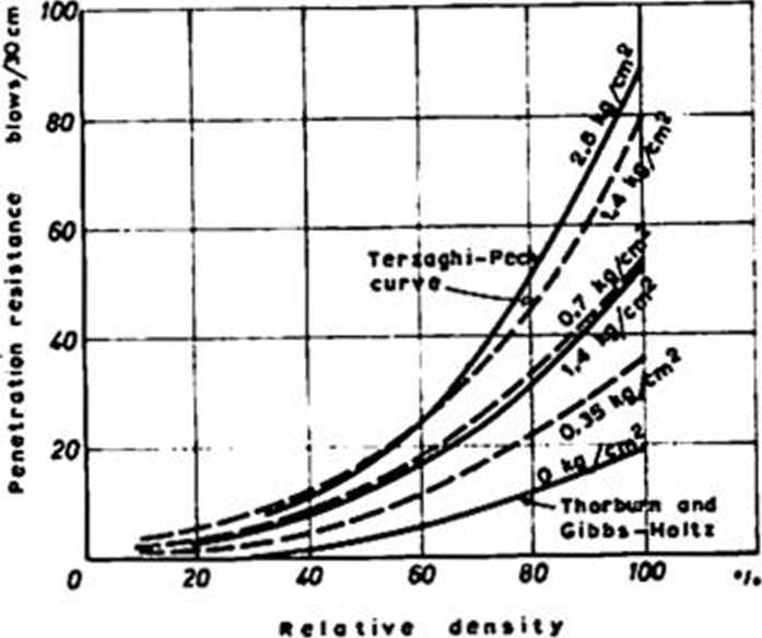
Fig. 1. Relationship between penetration resistan cc, overburden pressure and relative density for non-cohesive soils
- after H.J.Gibbs and W.G. Kolta
--- after S. Thorburn
In case of fine sands or silty fine sand at a rola t i vely dense State OJ' > 15) below ground water level, penetration resistance U’#has to be corre-
Wyszukiwarka
Podobne podstrony:
Penetration testing in Portugal esoptJ. Folque State-of-the-art
Penetration testing in Sweden esoptR. Dahlberg State-of-the-art
Penetration testing in Switzerland esoptP. Crettaz & H. Zeindler
Penetration testing in United Kingdom esoptS. Rodin, B.O. Corbett, D.E. Sherwood &
Penetration testing in Australia esoptJ.C. Holden State-of-the-a
Penetration testing in Bułgaria esoptG. Stefanoff & M. Bejkoff
Penetration testing in South Africa esoptD.L. Webb State-of-the-
Penetration testing in Czechoslovakia esoptK. Drozd & M. Svasta
Penetration testing in Denmark esoptA. Hansen State-of-the-art
Penetration testing in Federal Republic esoptof Germany E. Habetha
Penetration testing in Netherlands esoptW.J. Heijnen State-of-th
Penetration testing in Norway esoptK. Senneset State-of-the-art
ESOPT State-of-the-art reportPenetration testing in IsraelA. Komornik The most common type of penetr
skanowanie0037 (13) Cohen, A.D. 1989. Second Language Testing. In: Teaching English as a Second or F
USTREDNI KONTROLNI A ZKUŚEBNI USTAV ZEMEDELSKY Central Institute for Supervising and Testing in
Data Collection Anatysis In Greece "BRIDGE - Building Relationships through lnnovative Developm
więcej podobnych podstron