6781096724
Stanisław Gucma, Maciej Gucma
Navigational Systems supporting berthing manoeuvres (Docking System)
The idea behind the construction of a docking system is to facilitate berthing and unberthing of an LNG carrier by an accurate determination of ship hull position relative to the berth and equally accurate relative speed of the ship. Its main advantage is the determination of ship s distance to the quay independent of ship positioning systems as well as the measurement of hull transverse speed relative to the quay.
SIGGTO and OCIMF organizations recommend the use of docking systems as a support for LNG carrier berthing. The 1MO in the A.915 document sets out the accuracy levels for each type of naviga-tion (table 2).
The accuracy of 0.1 m can be ensured by satel-lite positioning receivers working with an extemal system source, such as the RTK system. Similar accuracy is yielded by a laser system operating on the quay, which, to its advantage, is independent of extemal factors affecting the position received via a satellite system.
The laser docking system for LNG vessels con-sists of the following components:
- extemal sensors, at least tvvo per quay, laser
or radar sensors;
- control system located at the operator’s room
on the quay;
- readout system, which may have different op-
tions, based on:
• large display located on the quay;
• light on the quay signaling that safe move-ment parameters have been exceeded;
• remote transmission, using portable recei-vers, mainly laptops or dedicated palmtops.
The systems which present information on mobile displays tum out to be better than boards in poor visibility. Such systems replace systems based on large display located on the quay, and additionally can be integrated with pilot navigation systems. Besides, remote systems can be used by skippers of tugs participating in un / berthing manoeuvres.
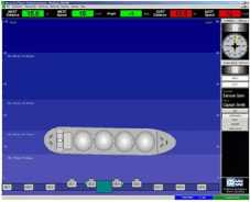
One example of a docking system is SmartDock madę by the Trelleborg Harbour Marinę. This laser system is based on remote data transmission. Its extemal sensors are shown in figurę 8, while figurę 9 depicts its portable display.
A similar solution is offered by Marimatech, a company that produces docking systems with

Fig. 8. Extcmal sensors of the SmartDock Harbour Marine-
Rys. 8. Zewnętrzne czujniki systemu SmartDock Harbour Marinę

Fig. 9. Portable display of the SmartDock system Rys. 9. Przenośny wskaźnik systemu SmartDock
Table 2. Accuracy standards developed by IMO Tabela 2. Standardy dokładności opracowane w IMO
|
IMO navigation requirements |
Accuracy |
Integrity |
Continuity over 3 hours |
Availability per 30 days | ||
|
Alert limit |
Time to alert |
Integrity risk | ||||
|
[m] |
[m] |
[s] |
1-5] |
[%] |
[%] | |
|
Ocean and Coastal |
10 |
25 |
10 |
10 |
N/A |
99.8 |
|
Port approach |
10 |
25 |
10 |
10 |
99.97 |
99.8 |
|
Port navigation |
1 |
2.5 |
10 |
10 |
99.97 |
99.8 |
|
Automatic docking |
0.1 |
0.25 |
10 |
10 |
99.97 |
99.8 |
50
Scientific Journals 20(92)
Wyszukiwarka
Podobne podstrony:
Stanisław Gucma, Maciej Gucma of ship’s position comes down to establishing the position of the wate
Stanisław Gucma, Maciej Gucma - redundant, as pilots tend to reject
WładzeRektor Akademii Morskiejprof. dr hab. inż. kpt. ż.w. Stanisław Gucma Swoje życie zawodowe od s
186 Stanisław Zając i znaczenia pracy. Dlatego systemy motywacyjne powinny oferować szeroką gamę
Stanowisko nr 3.GARMIN GPS III Plus Personal Navigator systemu GPS Opis układu pomiarowego. Ćwiczeni
Navigational systems employed on gas carriers while approaching terminals - determ
Navigational systems employed on gas carriers while approaching terminals Like in the IPPA system, t
Navigational systems employed on gas carriers while approaching terminals Navigational systems emplo
STANISŁAW A. HODOROWICZ MACIEJ HODOROWICZKRYSTALOGRAFIA NA UNIWERSYTECIE JAGIELLOŃSKIM PLACÓWKI
(26/04/13) 4 Materiały lotnicze - WBMiL 1 MDLiK (PRz 2012/2013) - dr inż. Maciej Motyka Klasyfikacja
Maciej Szmit metadanych systemu operacyjnego czy poszczególnych rodzajów dokumentów360) - określenie
naturane przeszkody Czyzkowko Grodzki Maciej Zakład usługowo System. Grandsperr- PHU &nb
więcej podobnych podstron