7696081226
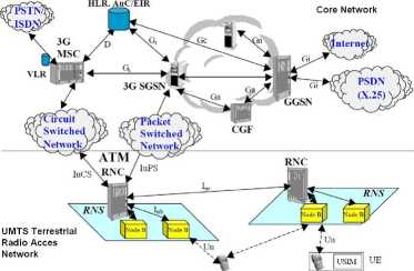
Figurę 4: Basic architecture of a UMTS mobile network (Release 99) (from [11]).
be reached. Figurę 5 shows the most recent proposal for the organization of a UMTS network: the all-IP multimedia network architecture defined in Release 5. The main feature of this architecture is that both voice and data are carried over IP packets all the way from the mobile station to finał destination, thanks to the addition of a new domain in the core network: the IP-Multimedia domain (IM).
The next is a brief description of the UTRAN components:
User Eąuipment/Mobile Station (UE/MS): Is the physical device used by users. It consists of a Mobile Eąuipment (ME) and an UMTS Subscriber Identity Module (USIM). The USIM is an application stored in a removable IC card which interoperates with the ME to provide access to 3G services and has the following features:
i Unambiguously identifies a subscriber i Stores subscriber and subscription related information i Authenticates itself to the network and vice versa (mutual authentication) i Provides security functions
i Stores information elements such as: preferred language, IC card identification, International Mobile Subscriber Identity (IMSI), cipher key, among others
Node B: Is the base transceiver station of the UTRAN that serves one or morę cells (sectors). Some of its functions include: error detection on transport channels and indication to higher layers, modulation/demodulation of physical channels, radio measurements and notification to higher layers and power weighting. Some vendors offer base stations that support both UMTS and CDMA2000 standards through the use of field-replaceable modules and a high percent of compatible hardware and software. The interface between UE and Node B (Uu in figurę 4) is actually the WCDMA-based UTRĄ radio interface.
Wyszukiwarka
Podobne podstrony:
Introduction 5 Figurę 1.2 The architecture of a PLMN.1.2.2.1 Mobile Station GSM-PLMN contains as man
00092 ?546ec4ad45fd72a0b658e111513581 91 A Very Simple Set of Process Control Rules Figurę 2 shows
9 preliminarily separated by means of LT TLC (see Fig. l(o)). Each of these three figures shows the
230 Illusion Stairway between corners of a fiat square. You can go from corner A to corner B by clim
Figurę 7. CQM online Coal Analyzer Figurę 8 shows the CQM Operator Console, on which are found trend
Security Architecture in UMTS Third Generation Cellular Networks Tomas Balderas-Contreras Rene A.
Security Architecture in UMTS Third Generation Cellular Networks Tomas Balderas-Contreras Rene A.
Evolution of network architecture Public Circuit- ~
Figurę 4. e-Informatyka portal architecture 4.1.1. Architecture of e-Informatyka portal Technologies
f3 1 C header and source files to implement native methods FIGURE 3.1 How the p rogranis of the JDK
FIG 08(1) Figurę 28. The inner mechanism of a magnelic lock is rather simpEe. Figurę 29. The magneli
więcej podobnych podstron