
613
In This Chapter
21
Surfacing Wireframe
Models
This Autodesk
®
Mechanical Desktop
®
tutorial introduces
wireframe surface modeling, one of the key uses for
surface modeling. You learn how to develop a strategy for
a surfacing project, and how to achieve the design intent.
The tutorial provides instructions for surfacing a
wireframe model of a pump housing. The wireframe is
the outline of a pump housing, and the only data you
have to work with.
You should already know how to create surfaces before
you begin this tutorial. If you do not, complete the
exercises in chapter 19, “Creating and Editing Surfaces.”
■
Studying the design intent and
developing a strategy
■
Identifying logical surface areas
■
Identifying base surface areas
■
Using creative techniques to
surface a wireframe model
■
Verifying surfacing results

614
|
Chapter 21
Surfacing Wireframe Models
Key Terms
Term
Definition
base surface
A basic underlying surface that carries a shape across a larger area. Can be trimmed
to precise shapes as needed, but the base surface remains intact and may be
displayed.
logical surface area
An area that can be described by a single surface.
projected wire
A 2D line that represents an opening on a surface and trims a hole in the surface.
Can also be a 3D polyline that represents the extents of the opening in the
wireframe.
watertight
Surfaces conform to the wireframe model; gaps between surfaces are within
allowable tolerances.

Basic Concepts of Surfacing Wireframe Models
|
615
Basic Concepts of Surfacing Wireframe
Models
A completely surfaced model is a single electronic master suitable for engi-
neering and manufacturing activities, such as:
■
Generating accurate sections for engineering and packaging studies.
■
Providing input for finite element modeling and analysis.
■
Producing shaded renderings for marketing.
■
Providing input for rapid prototyping equipment.
■
Supplying rotated surfaces for tool, mold, and die design.
■
Supplying surfaces for numerical control machining of models and tools.
In this tutorial, building on your knowledge of surface types, you examine
the wireframe to be surfaced and determine which surface will produce the
best results.
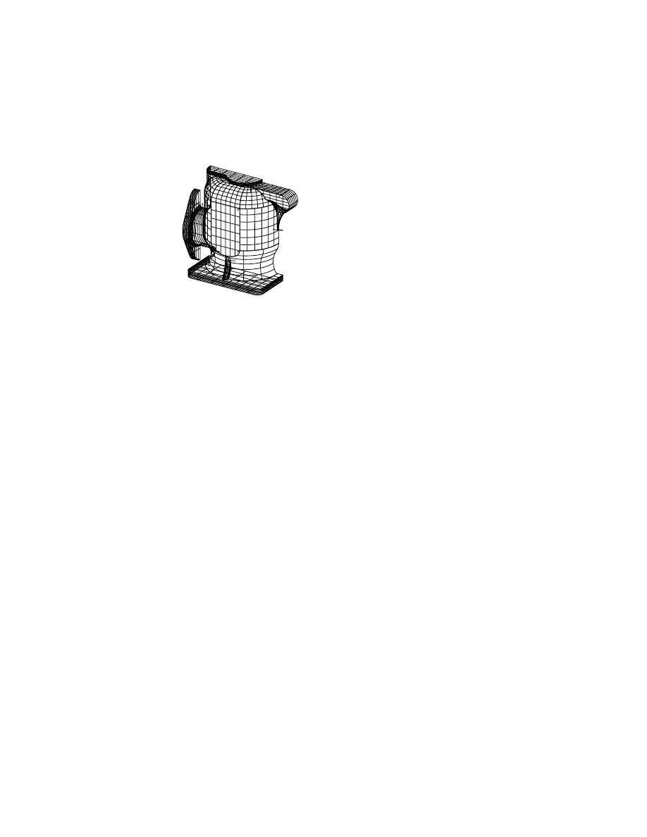
Discerning Design Intent
Because wireframe models have complex shapes, they are usually made up of
many surfaces joined together. For a model like the pump housing, you will
use many different individual surfaces to completely define it. When you sur-
face a wireframe model, you complete its design.
Before you begin, analyze the design and then plan how you can achieve
your design goals. This process of planning before you begin modeling can
help you avoid errors. For example, you usually follow these steps for wire-
frame modeling:
■
Study the data to understand the design intent.
■
Identify the location and extent of each surface area.
■
Identify the base surface area(s) that can be trimmed later to adjacent sur-
faces and wires.
■
Determine where you can use trimmed planar (flat) surfaces.
■
Decide on the best surface types and approach for combining them.
■
Create additional geometry as needed to resolve problem areas.
■
Verify your surfacing results.
■
Add the finishing touches to a watertight model.
616
|
Chapter 21
Surfacing Wireframe Models
Review the wireframe in detail, to determine where you will have design
challenges.
Consider the following:
■
The complexity of the surfaces you need to create. For example, what
curvature is required of surfaces? Is it sufficient to have surfaces with no
curvature (such as ruled surfaces), or do you need surfaces with multiple
curvatures?
■
How you can simplify shapes. Surfaces created from polylines or splines
with a large number of points are complex and greatly increase computa-
tion time.
■
Which surfaces are continuous. Continuous surfaces are smoother and
take less time to compute. You can set preferences so that lines with breaks
or changes in curvature aren’t converted to splines.
■
Are default preference settings appropriate for the model. Allow as much
tolerance as is practical to avoid converting polylines to splines. Splines
take longer to compute than polylines—a factor that becomes more
important with complex models.
Identifying Logical Surface Areas
Once you determine the intent of the pump design, you get an idea of the
requirements for creating its shape and for constructing it. Identify the loca-
tion and extent of each logical surface area—an area that can be described by
a single surface.
A surface must be smooth and free of sharp breaks. Often, an individual sur-
face area is clearly-defined because it is surrounded by sharp break lines on
all sides. The pump top is a surface because it is surrounded by sharp edges
on three sides. The fourth edge is the end of the part.
Basic Concepts of Surfacing Wireframe Models
|
617
Likewise, the side of the top part of the pump constitutes a single surface.
Each of these two surface areas requires a surface because no single surface
could cover both.
Surfaces can contain multiple wires.
All lines inside the four boundaries share the same smooth curvature as the
boundary edges. There are no abrupt curvature changes, so the goal is to sur-
face the entire area with a single surface, using the additional wires to con-
strain the surface shape.
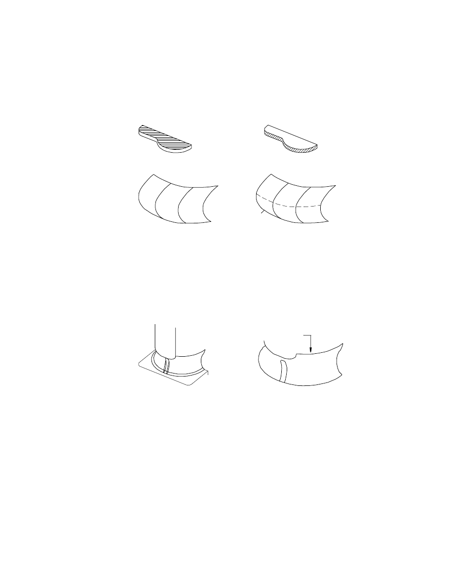
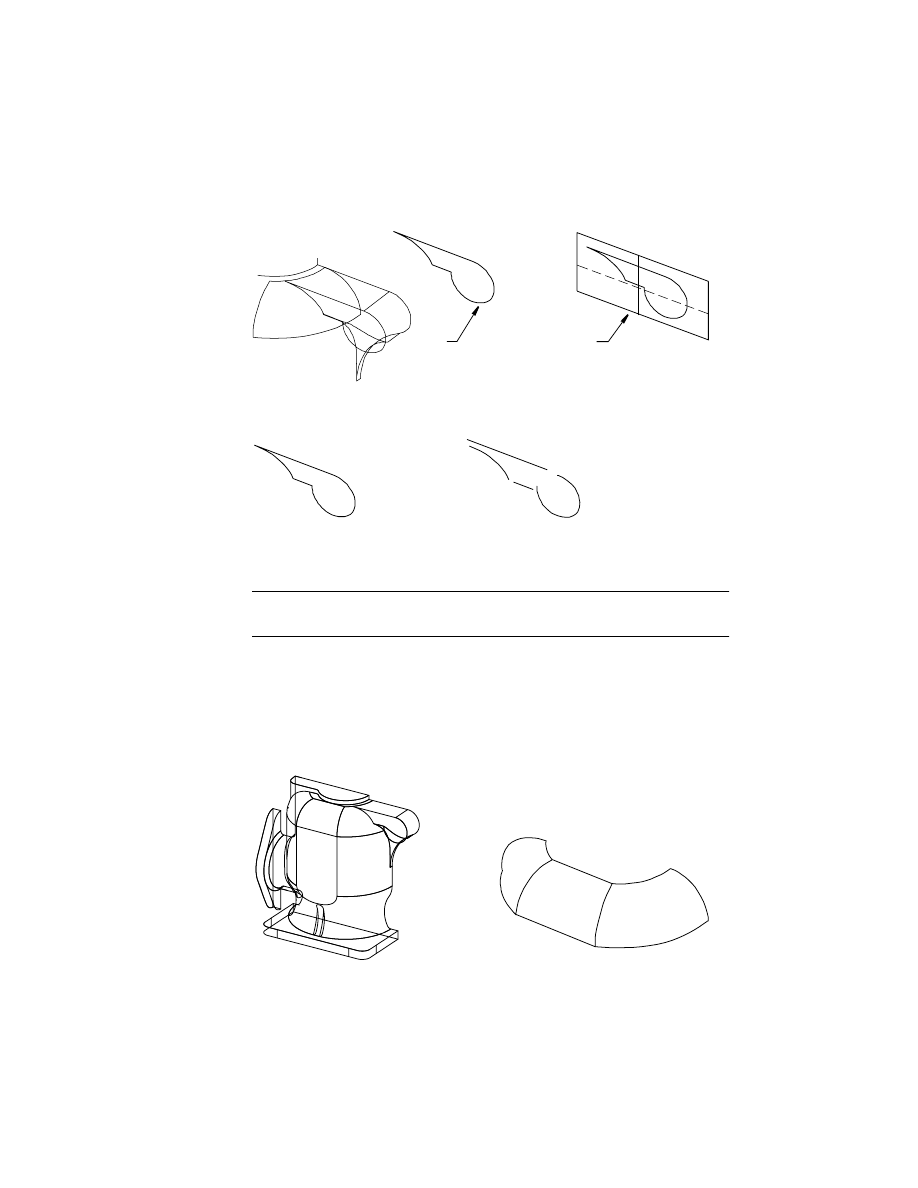
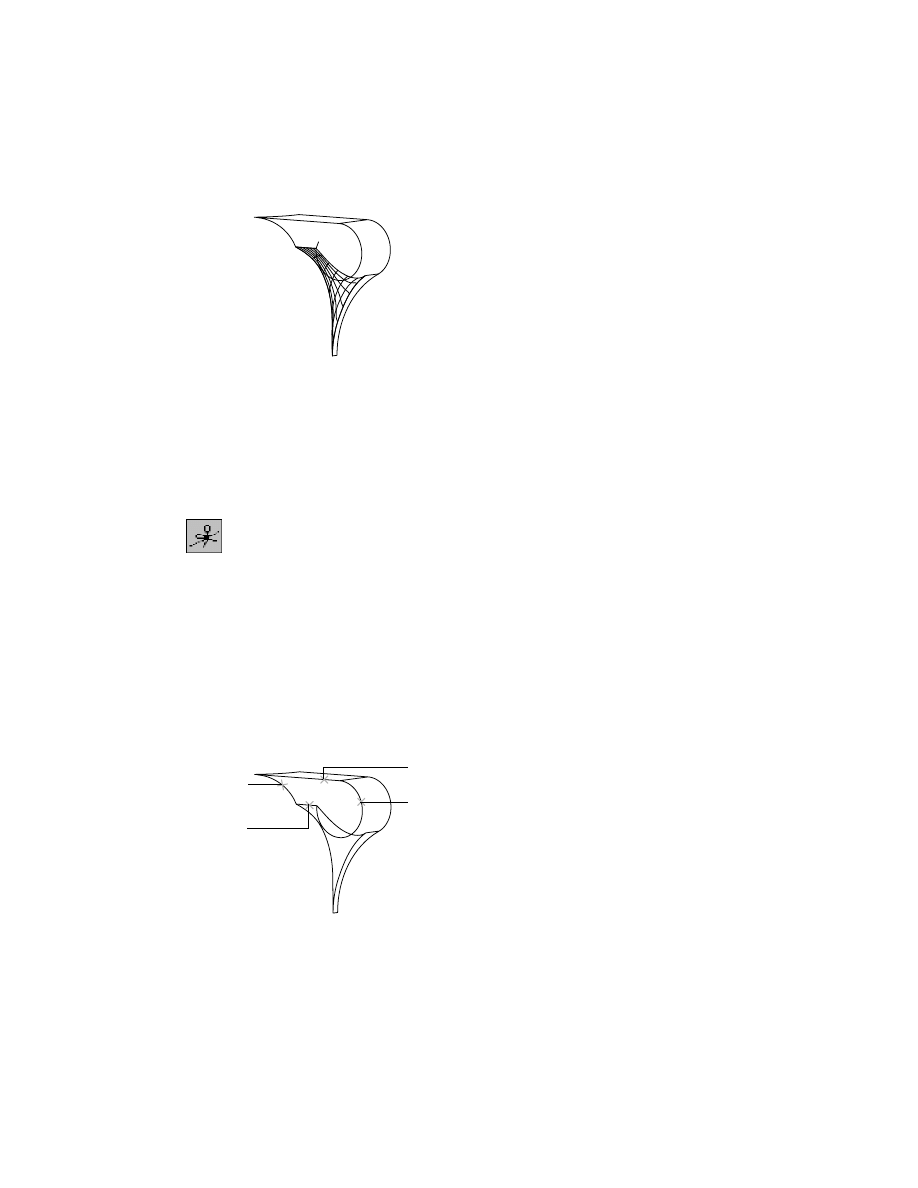
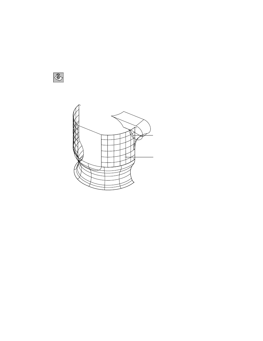
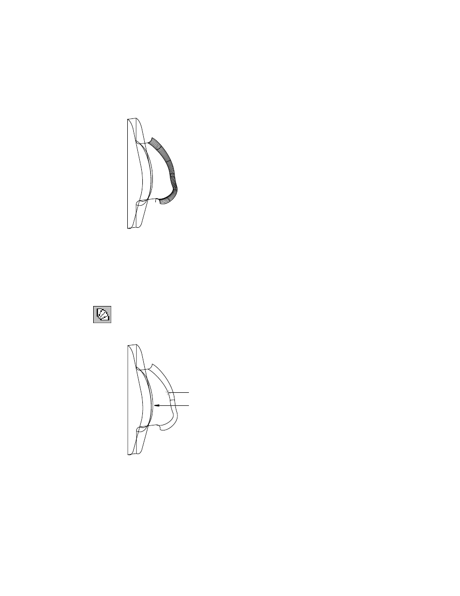
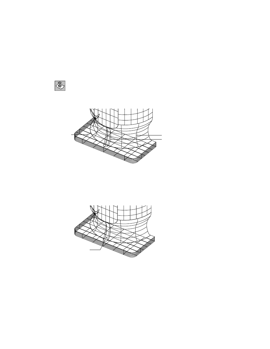
Identifying Base Surface Areas
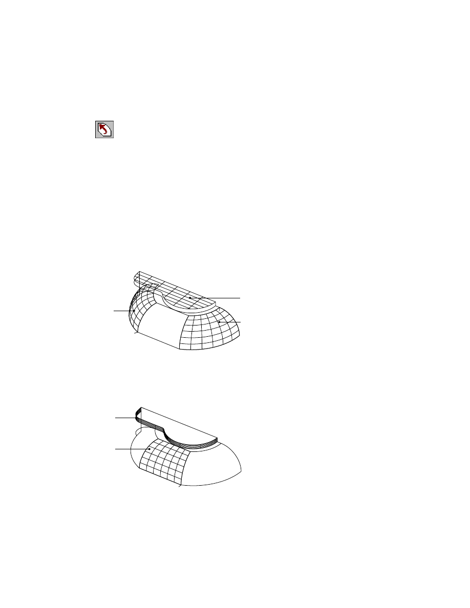
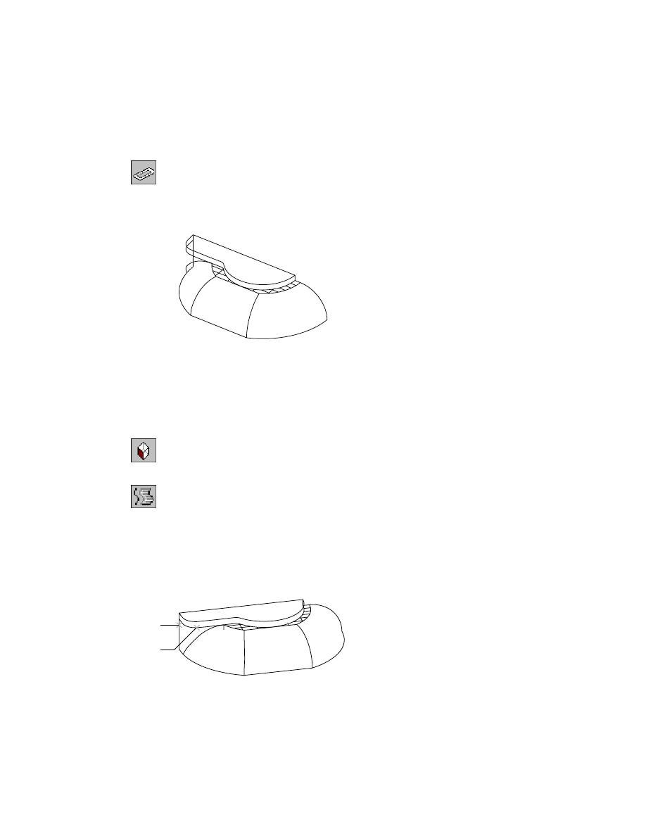
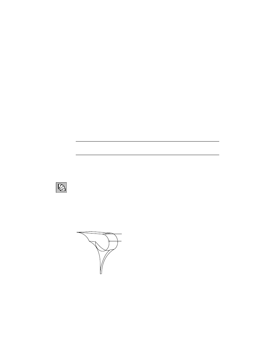
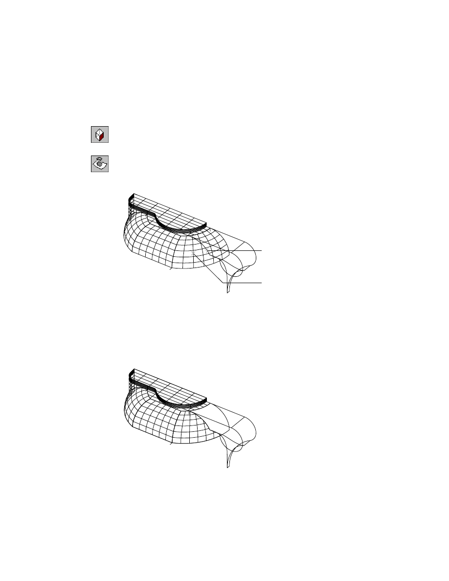
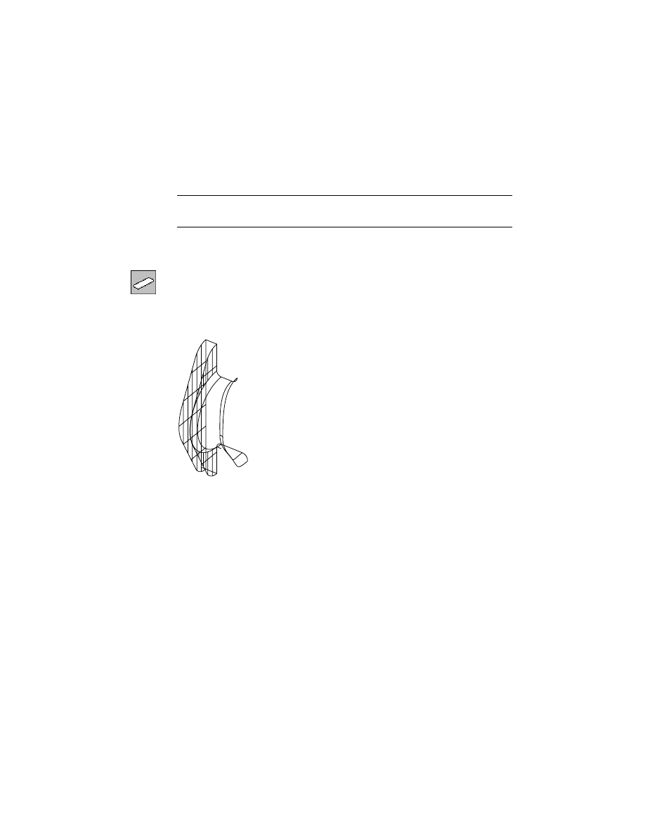
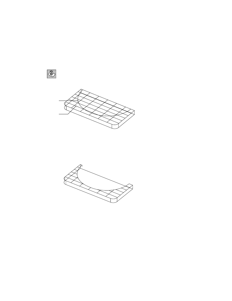
The bottom of the pump housing appears to be a smoothly-curved area.
However, at the top edge, there is an almost 90-degree bend. Also, a flanged
area is formed by a slot opening in the otherwise smooth area.
The primary guideline in wireframe surfacing is to create an acceptable sur-
face first. Later, add a hole by trimming the surface with the shape of the
hole.
wireframe
surface
pump housing
close-up
top edge
618
|
Chapter 21
Surfacing Wireframe Models
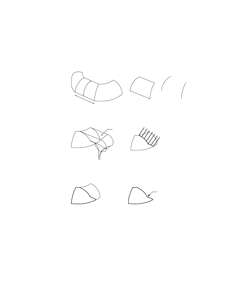
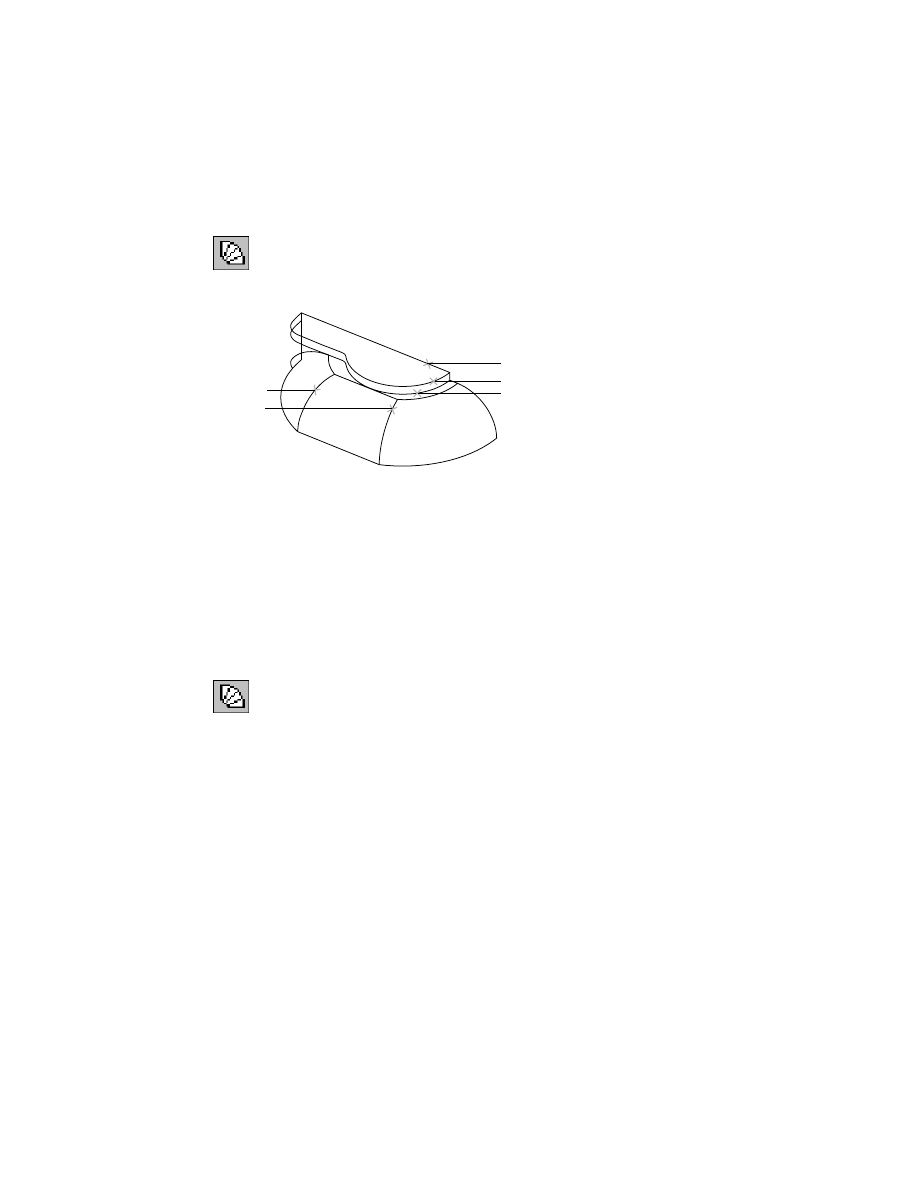
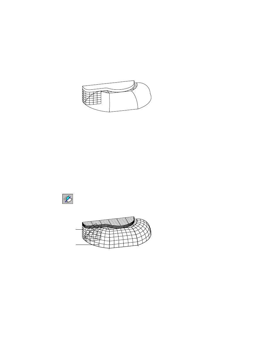
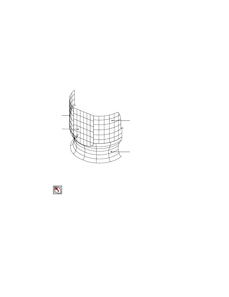
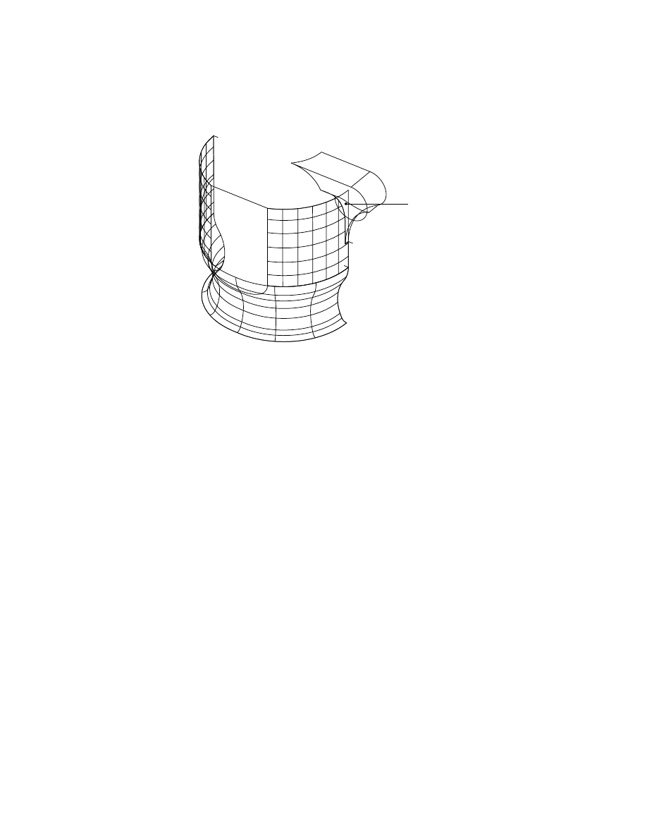
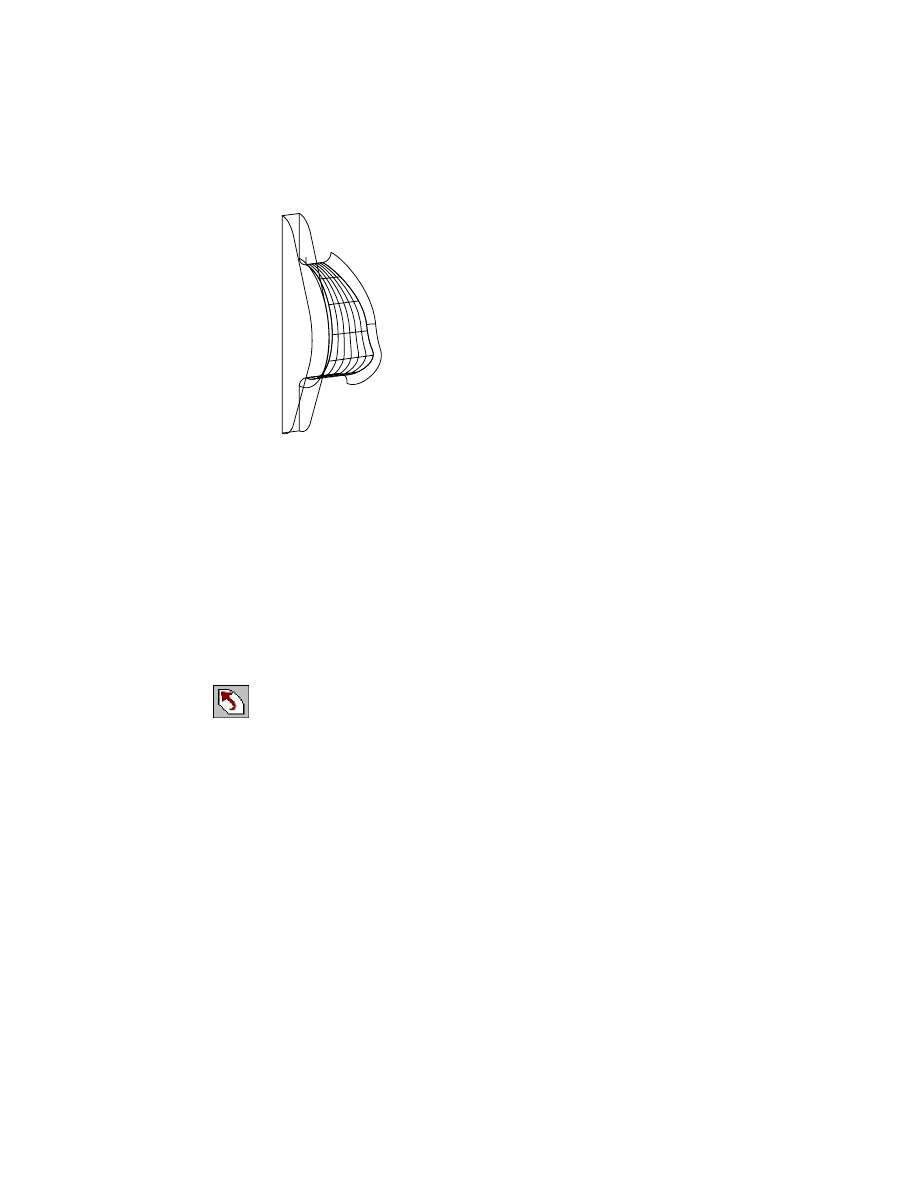
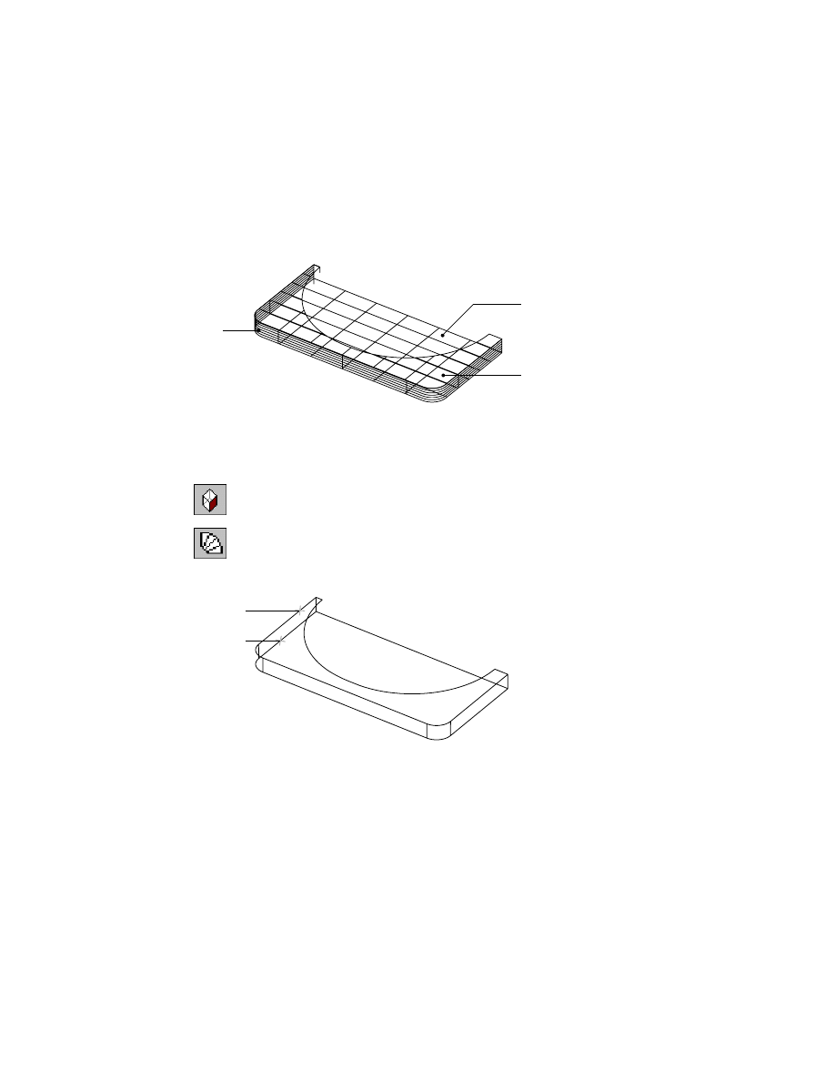
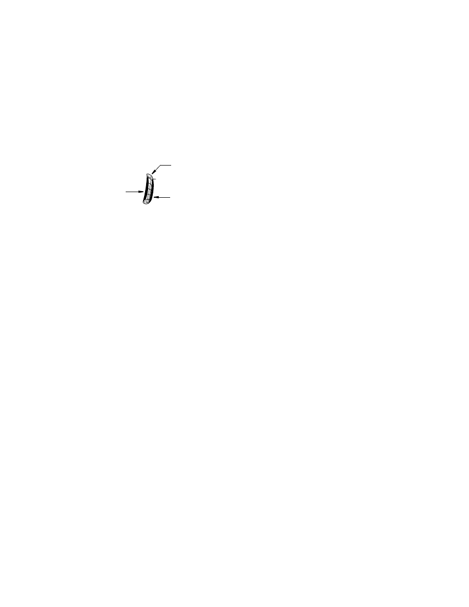
In general, use only smooth wires to create surfaces. When you use a wire
with sharp corners, those sharp areas do not produce an acceptable surface.
You need to find some other way to surface the area. Consider the design
intent again. A second look at the area reveals a flat surface on the front of
the pump housing that intersects a smoothly curved surface at the bottom.
How do you know that the front surface is flat? One way to check is to look
at the top line in another view. The approach to surfacing that area is to cre-
ate the smooth bottom surface and the flat surface. Then intersect one with
the other and create a wire at their intersection. If the new wire is the same
as the existing wire, you confirm your observation and surfacing approach.
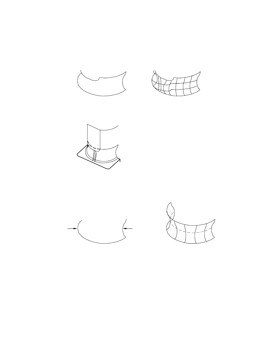
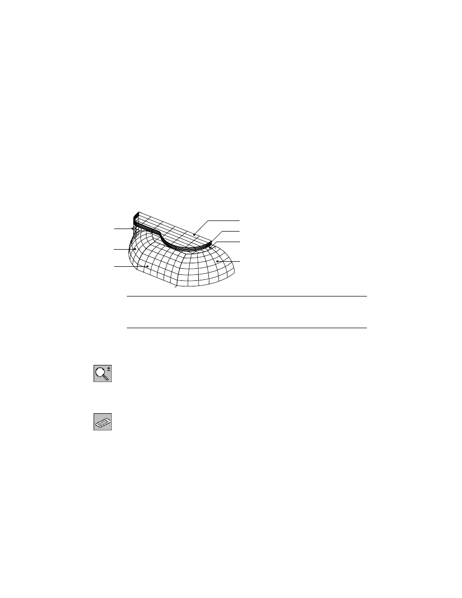
Next, consider the bottom surface. You already know that you cannot use the
top wire because it has an abrupt corner. A good approach is to use only the
bottom wire as a rail, and the far edge as a cross section.
wireframe
unacceptable surface
rail
section
surface
Basic Concepts of Surfacing Wireframe Models
|
619
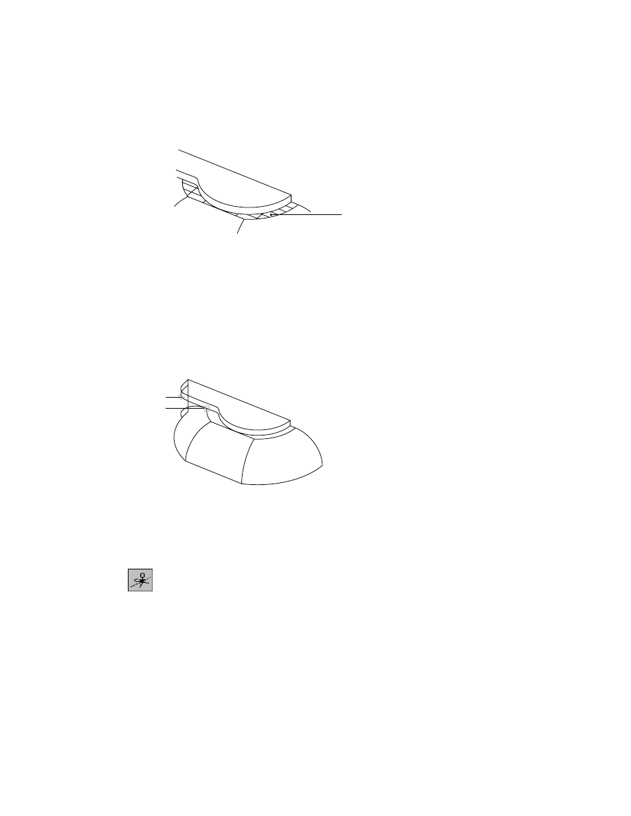
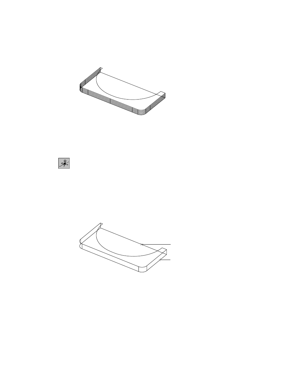
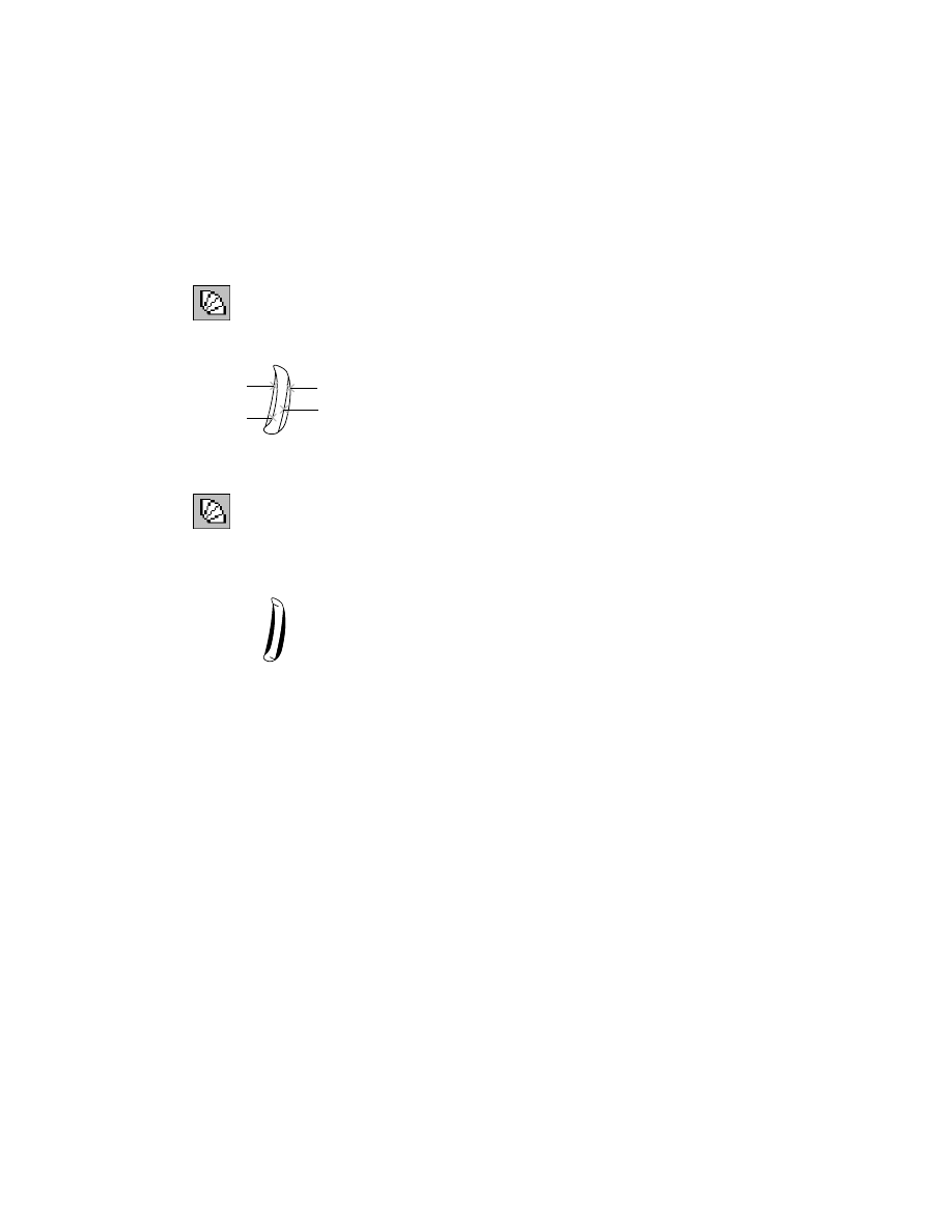
A surface like this one is a basic surface that carries a shape across larger areas.
This surface is referred to as a base surface. Even after many areas of the sur-
face are trimmed away, the underlying base surface remains intact and may
be displayed at any time with the Surface Display dialog box.
Identifying base surfaces is an important part of wireframe surfacing.
Another approach is to categorize surfaces by type and eliminate those you
won’t need.
To get shapes you can use for creating surfaces, you may need to break poly-
lines into segments. Then combine selected segments to form boundaries for
individual surfaces.
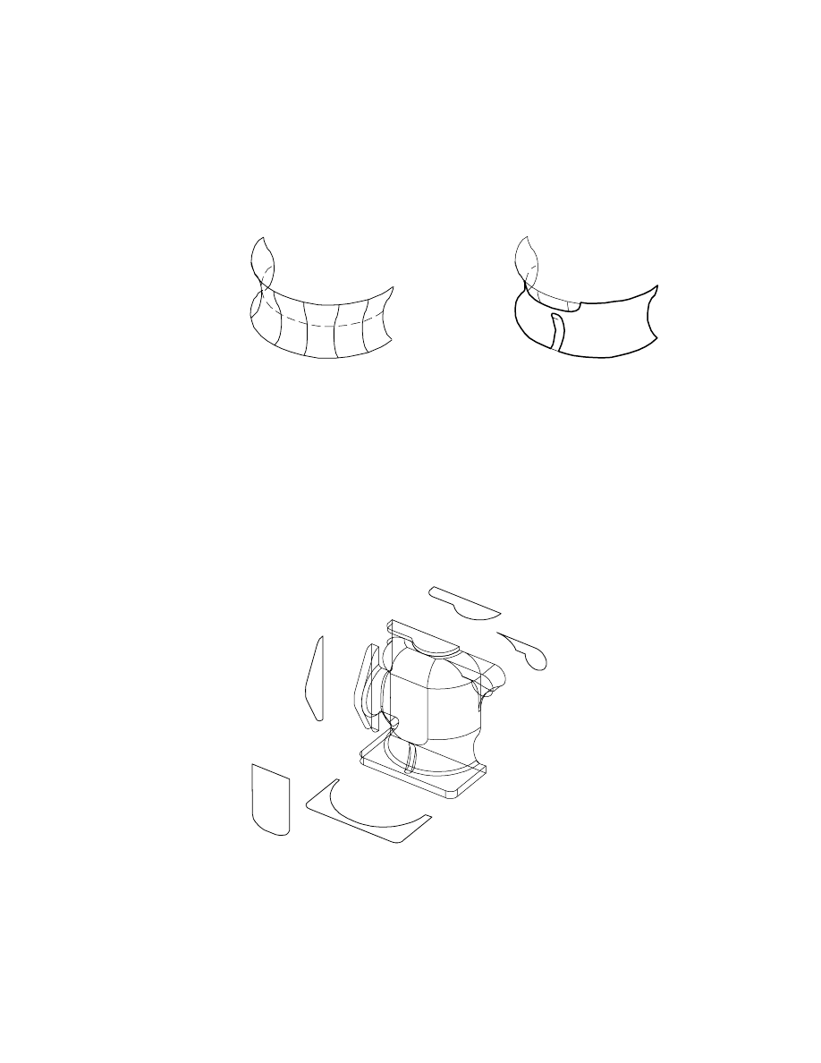
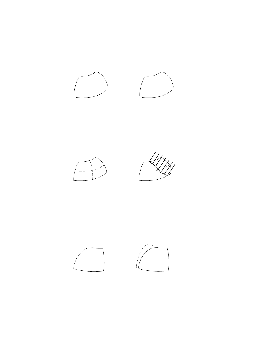
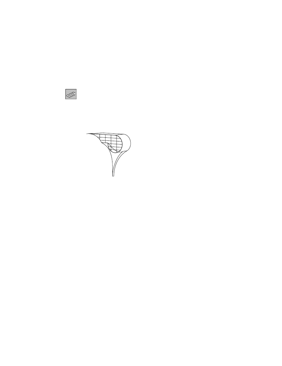
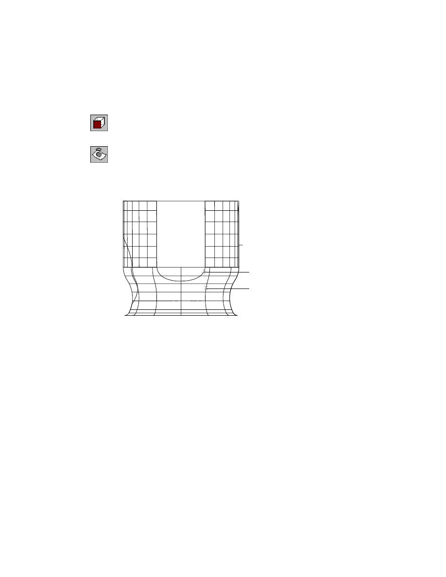
Using Trimmed Planar Surfaces
Use a trimmed planar surface for an area that you know is a flat plane. By
glancing at the pump model, you can see areas that appear to be flat and can
be surfaced with trimmed flat planes.
base surface
trimmed surface
620
|
Chapter 21
Surfacing Wireframe Models
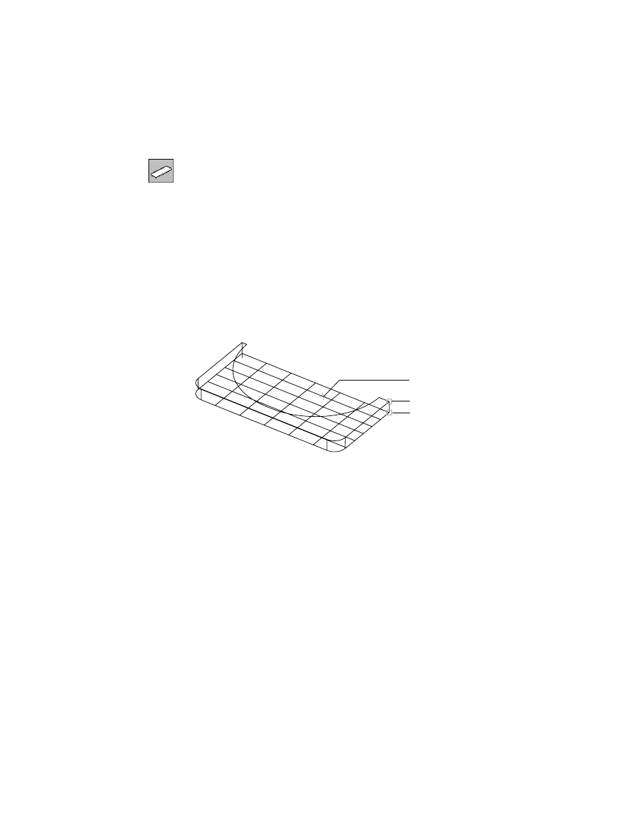
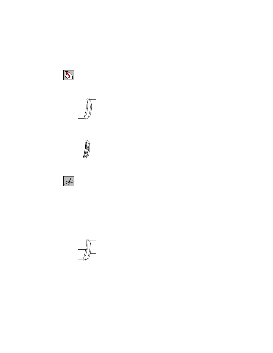
If you are in doubt about whether a given area is flat, try to make a planar
surface. A planar surface requires a single closed wire as its boundary.
If the wire is not a closed single loop, you can see the breaks in the wire when
you select it.
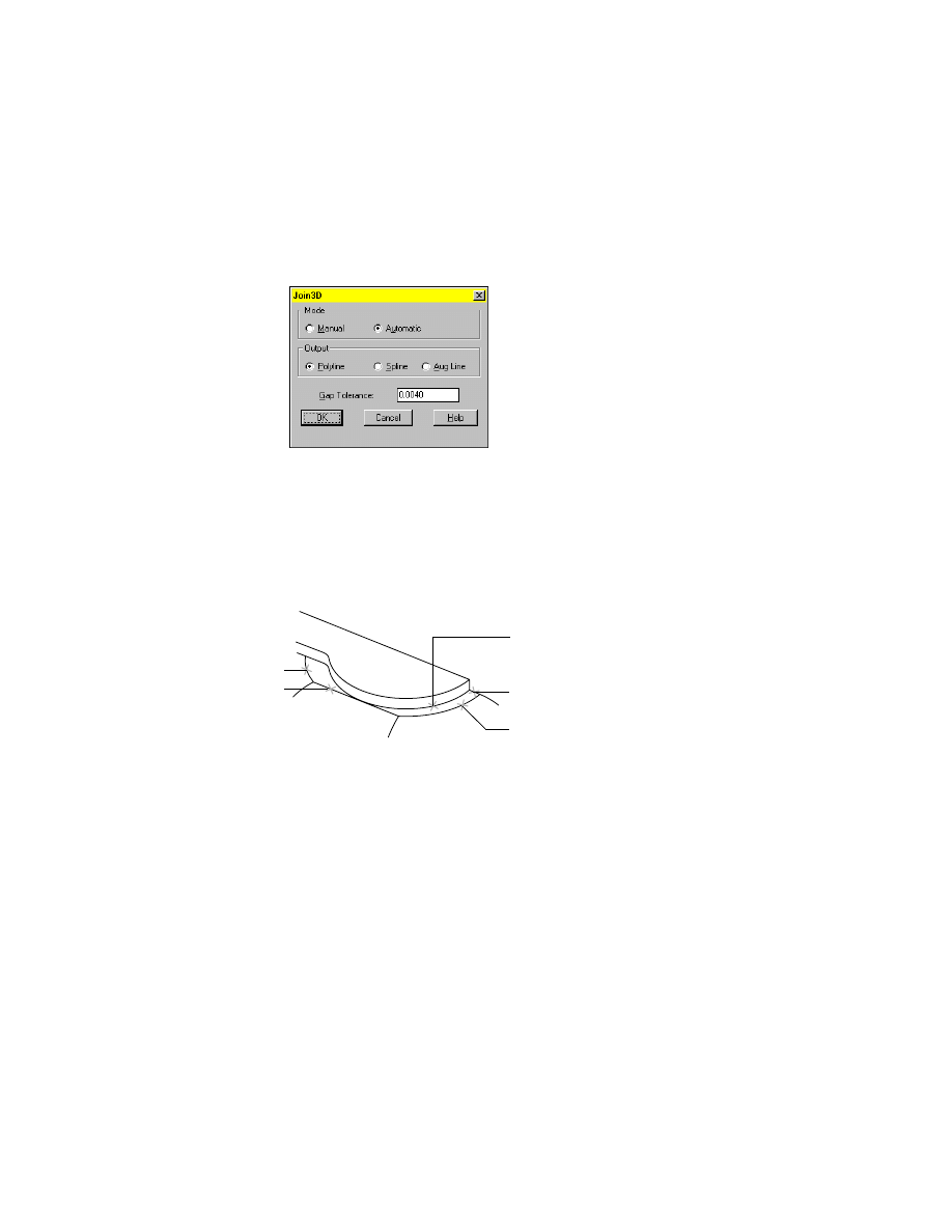
You can join line segments into a closed wire that forms the boundary of a
planar surface. The surface is trimmed to the boundary shape.
NOTE
When joining line segments, set tolerances to compensate for imper-
fect wireframe data that would otherwise cause the surface to fail.
Determine if an area is meant to be flat. If it is flat within the tolerance, create
a flat surface and adjust the edges.
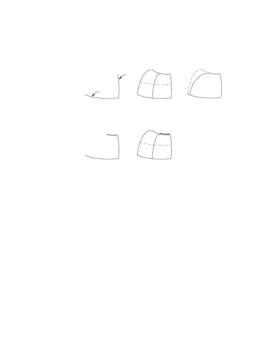
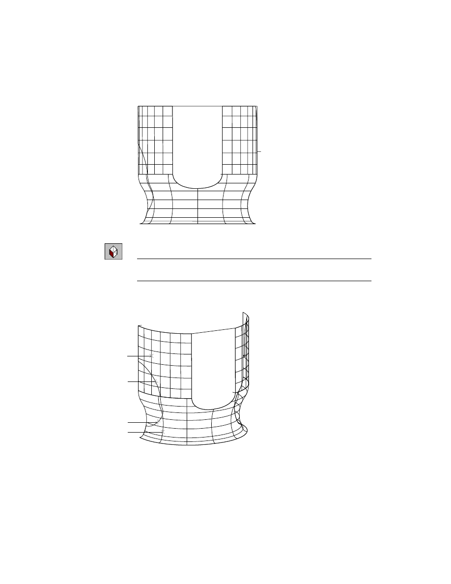
Choosing a Surfacing Method
Which type of surface is best suited for a given area may not be clear.
wire
planar surface
closed wire
multiple wires
top area
Basic Concepts of Surfacing Wireframe Models
|
621
In this example, the top area of the pump is not suitable for a single surface
because there are abrupt changes in its smoothness. The center area is curved
in one direction but straight in the other. When you have a surface area that
can be defined by a straight line between two curves, you can create a ruled
surface between the two curves.
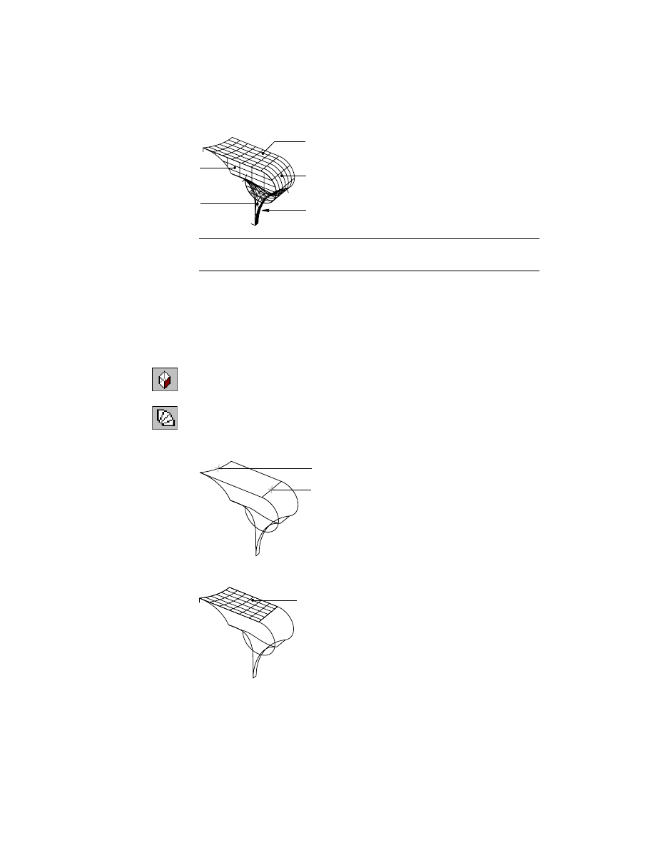
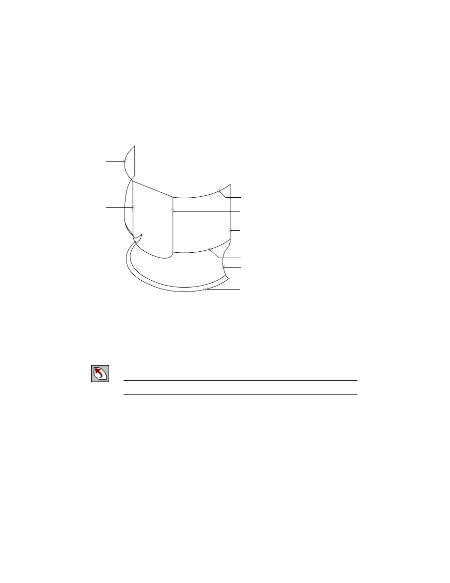
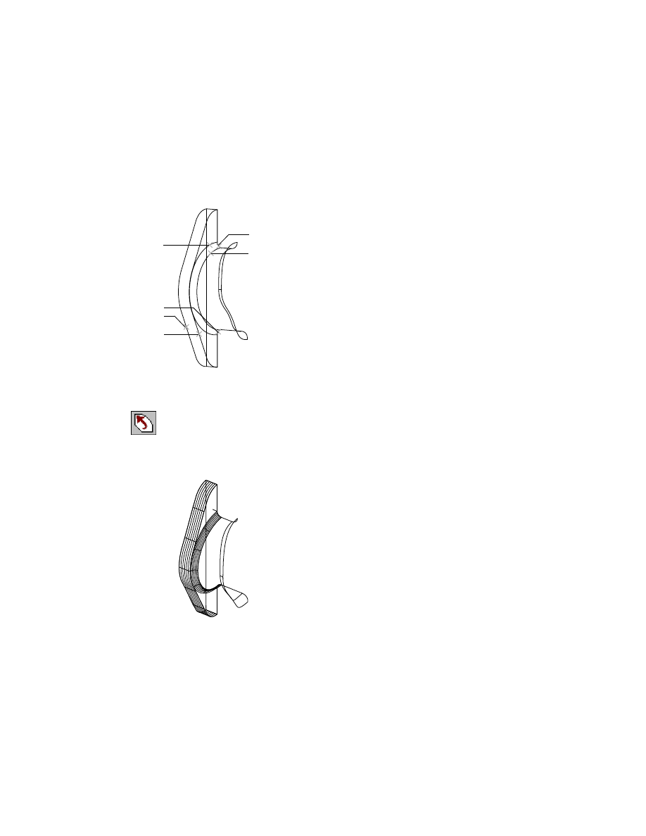
Look beyond the obvious visible surface to find a workable solution. Because
the inlet at the right top area of the pump extends from the surface, consider
making the base surface first and then trimming it to the correct shape.
With the inlet shape removed, you can see possibilities for surfaces. The
shape created by the four wires contains a sharp corner. Avoid creating a
surface from these four wires because they might produce a surface that is
not smooth.
possible surface
wire
inlet
abrupt corner
622
|
Chapter 21
Surfacing Wireframe Models
You can see that each end of the area beneath the inlet is described by lines
with curvatures in both directions. This offers you a choice of surfacing
methods, such as a swept surface or a lofted UV surface.
In most cases, there is more than one way to surface an area. Try both methods
here, compare the results, and choose the one that produces the best result.
■
Swept surfaces give you more control over the shape of the mid portion of
the surface.
■
Lofted UV surfaces have fewer controls but risk is minimized.
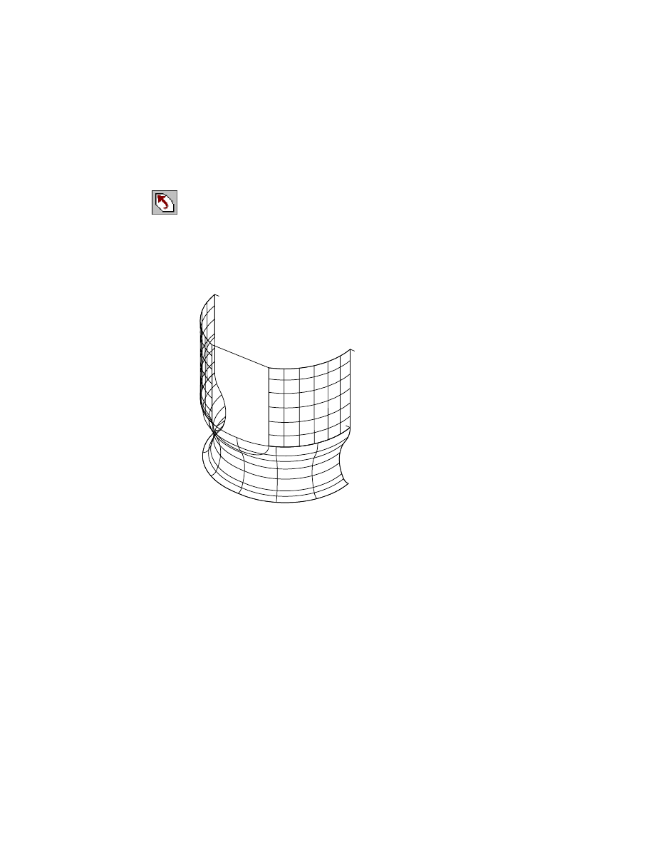
Once you create a base surface to cover an area, trim the surface back to the
wire with the abrupt edge.
Use trimmed surfaces to create smooth underlying base surfaces that remain
a permanent part of a surface definition. Trim to constrain the edges and you
achieve smoothness in a base surface that contains no abrupt corners in its
boundary wires, yet creates a logical surface bounded by different edges. The
logical surface can contain any number of sharp corners, which have no
effect on the smoothness of the base surface.
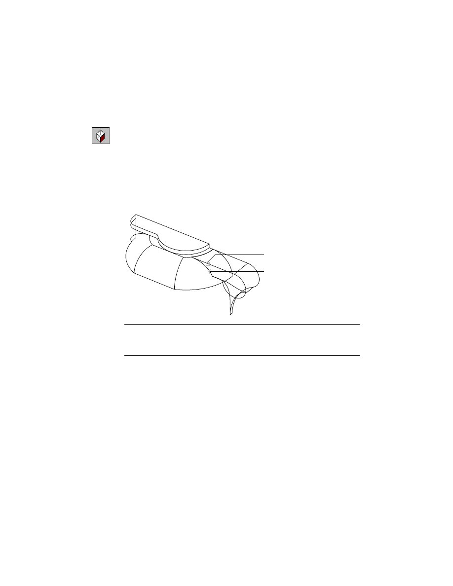
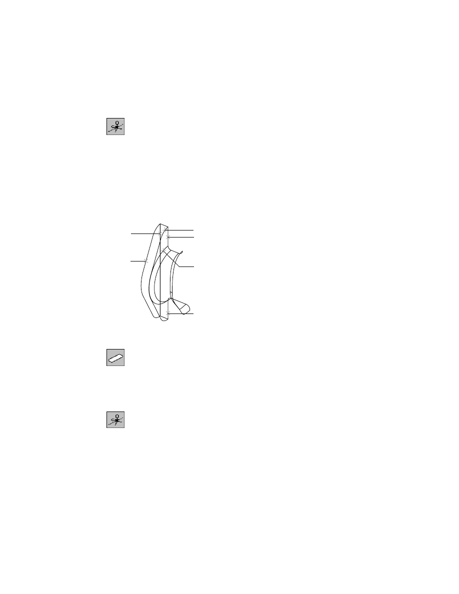
The opposite side of the pump top area may also be surfaced several ways.
Again, the surface is really a larger surface cut short by an intersecting area of
the pump. This time, the wire that terminates the surface has no abrupt cor-
ners, so it could be used as one of four sides of a swept or lofted UV surface.
swept surface
lofted UV surface
base surface
trimmed surface
Basic Concepts of Surfacing Wireframe Models
|
623
The easiest method is to use a single rail and a single section to surface the
entire area, then trim the base surface to the intersecting part of the pump.
This choice might not always be correct. As you gain experience, you can pre-
dict which approach yields the most accurate results. In the previous exam-
ple, verify that the surface created without the top line matches the top line
within a reasonable tolerance.
Always check the fit between a newly created surface and existing wires to be
sure that you are not deviating too far from the wireframe data. If the new
surface is not within tolerance to the existing top line, the surface does not
accurately reflect the wireframe. You can re-create it using all four wire edges.
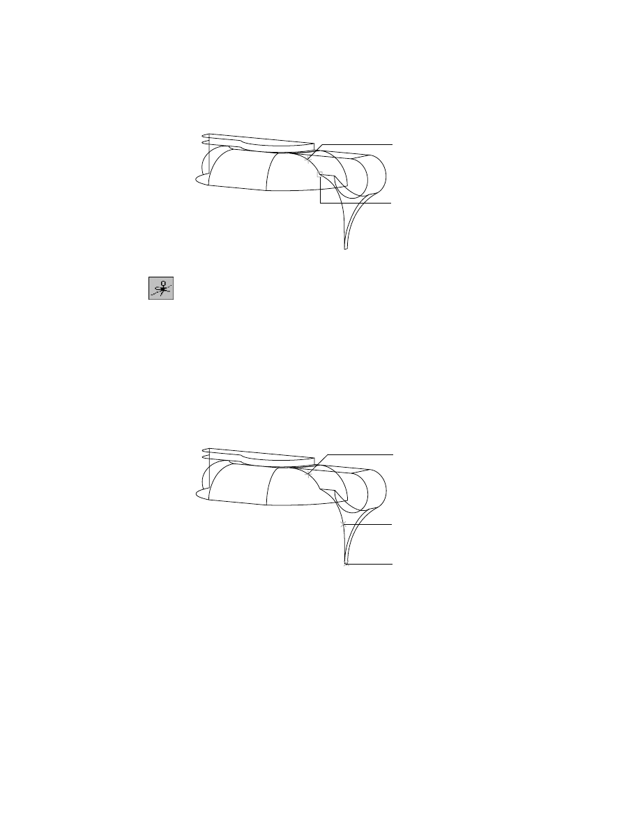
Verifying Surfacing Results
As you gain experience, you will see the importance of learned skill and judg-
ment. Your challenge is to produce smooth surfaces that fit the wireframe
closely; the surfaces should be as simple as possible.
You can judge the smoothness of surfaces several ways:
■
Analyze a surface and view its color-shaded display to detect small devia-
tions in surface smoothness.
■
Create and review flow lines in different rotated views.
■
Cut sections through a complete set of surfaces, and then examine the
ends to see how closely they match at the edges.
■
On the surface create augmented flow lines with long vectors and examine
the smoothness of the vector ends. The ends of the vectors exaggerate the
smoothness of the surface; areas where it is not smooth become apparent.
rail
section
surface
trimmed surface
624
|
Chapter 21
Surfacing Wireframe Models
Surfacing Wireframe Models
Now that you have analyzed approaches to surfacing the pump housing and
practiced surfacing techniques, you are ready to surface the pump.
A surface modeling project may begin with a wireframe, whether it is a DXF
or an IGES file from a client, or a 2D or 3D CAD design you created yourself.
In order to describe the 3D object, most designers begin with a 2D drawing.
In this lesson, you create surfaces for an actual part, a wireframe model of a
hydraulic pump. The surfaced model provides the manufacturer with infor-
mation to create prototypes or to NC-machine patterns, molds, and tooling.
To set up a drawing file
1
Open the file t_pump.dwg in the desktop\tutorial folder.
NOTE
Back up the tutorial drawing files so you still have the original files if you
make a mistake. See “Backing up Tutorial Drawing Files” on page 40.
2
Use
AMOPTIONS
to set the surfacing options.
Desktop Menu
Surface ➤ Surface Options
In the Mechanical Options dialog box, select the Surfaces tab. In Surface
Properties specify:
U Display Wires:
Enter 5
V Display Wires:
Enter 5
In Surface/Spline Options, specify:
Polyline Fit Length:
Enter 1
Polyline Fit Angle:
Enter 150
Choose Model Size.
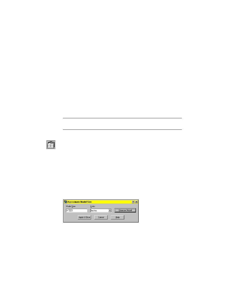
3
In the Approximate Model Size dialog box, choose Measure Model.
The Model Size is 4.7223. Choose Apply & Close.
Surfacing Wireframe Models
|
625
Notice that the values have changed in the Mechanical Options dialog box.
These settings affect the visual representation of the surfaces and the size of
the surface normal. Choose OK to exit.
NOTE
If you shade the surfaces you create to better view them, adjust the
AutoCAD
®
setting that controls back faces. Go to Assist ➤ Options and select the
System tab. Choose Properties and clear the check box beside Discard back
faces. Choose Apply & Close, then OK.
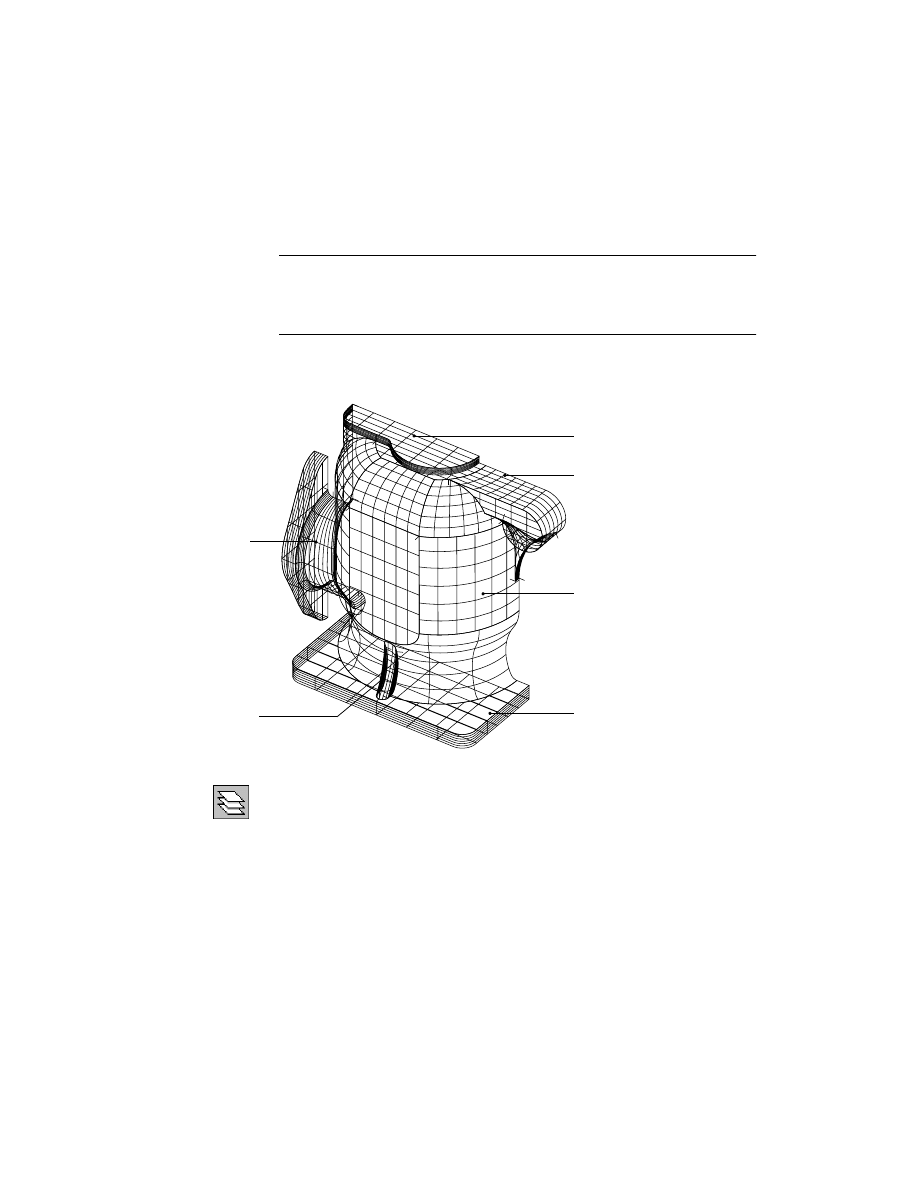
The labeled parts of the pump are on separate layers. As you work on a part,
you make its layer current and freeze the other layers to make them inactive.
4
Use
LAYER
to set up your current layer.
Desktop Menu
Assist ➤ Format ➤ Layer
5
In the Layer Properties Manager dialog box, highlight layer
10
and click Make
Current.
6
Select layer
20,
then press
SHIFT
and select the last layer. In the second col-
umn, click the sun icon under Freeze to freeze all selected layers. Then freeze
layer
0
.
All layers except Layer
10
should be frozen (snowflake icon). Only Layer
10
is
thawed (sun icon). Choose OK.
outlet
body
inlet
top
base
support
626
|
Chapter 21
Surfacing Wireframe Models
Creating Trimmed Planar Surfaces
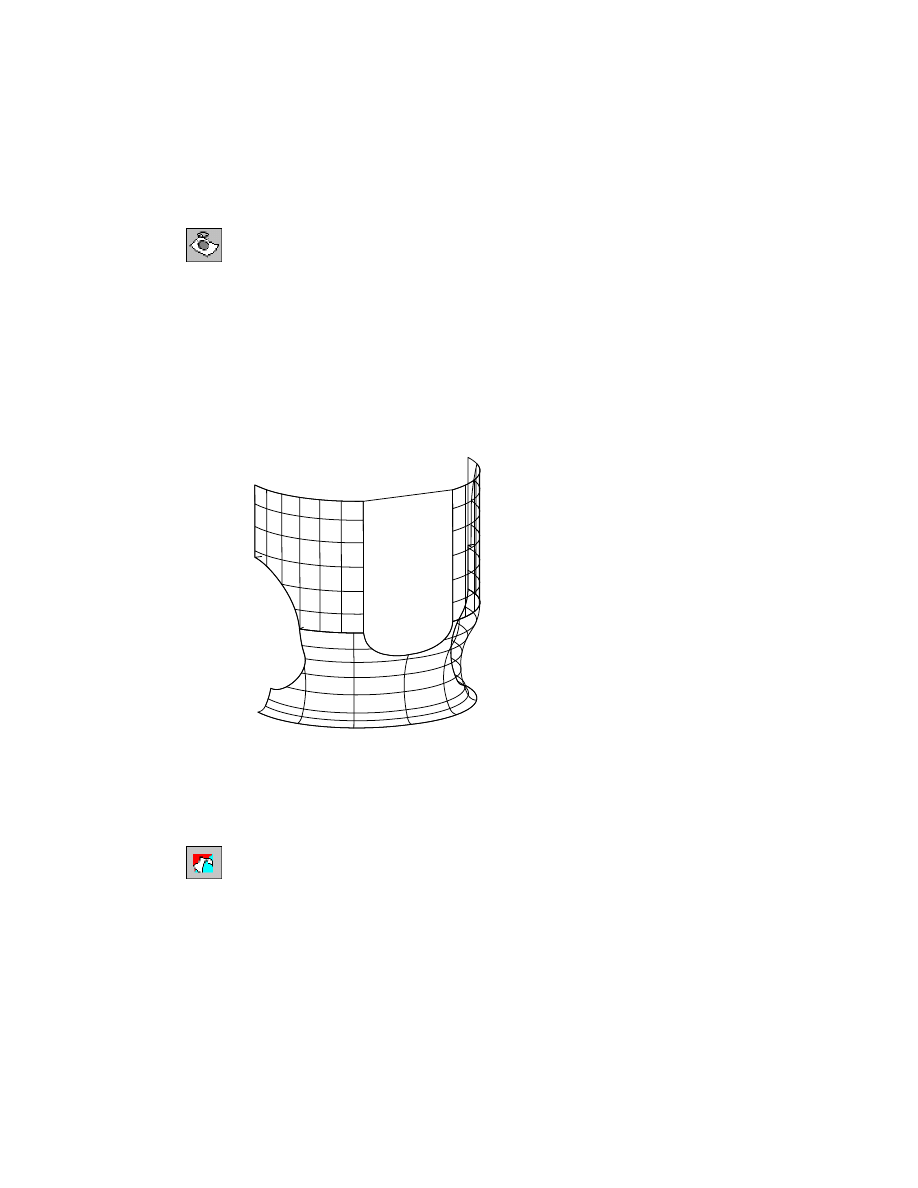
Begin by surfacing the top section of the pump model, creating the individ-
ual surfaces. Top A is a planar surface because it is flat with sharp edges. Tops
B and C are swept surfaces, bounded by curved wires. Top B uses two curves
and two rails, and top C uses one curve and one rail. You trim the top C sur-
face where it extends beyond the wireframe boundary.
As you gain experience using the menu selections that correspond to com-
mands, you may want to use shortcuts. For a list of shortcuts that automate
the selection of menu options and commands, see “Accelerator Keys” in the
online Command Reference.
NOTE
For a trimmed planar surface, the surface must be a single polyline that
lies in a single plane. If the wireframe is composed of multiple polylines, join
them into a single polyline before you create the surface.
To create a trimmed planar surface
1
Use
ZOOM
to enlarge the view, responding to the prompt.
Context Menu
In the graphics area, right-click and choose Zoom.
[All/Center/Dynamic/Extents/Previous/Scale/Window] <real time>:
Press
ENTER
2
Use
AMPLANE
to create the top A surface, responding to the prompt.
Desktop Menu
Surface ➤ Create Surface ➤ Planar Trim
If you use the command line method, enter w at the prompt before continu-
ing to the following prompt.
top G
top C
top D
top A
top E
top F
top B
top A
Creating Trimmed Planar Surfaces
|
627
Select wires:
Select wire (1) and press
ENTER
A planar surface, trimmed to the boundary of wire (1), is created on the top
of the model.
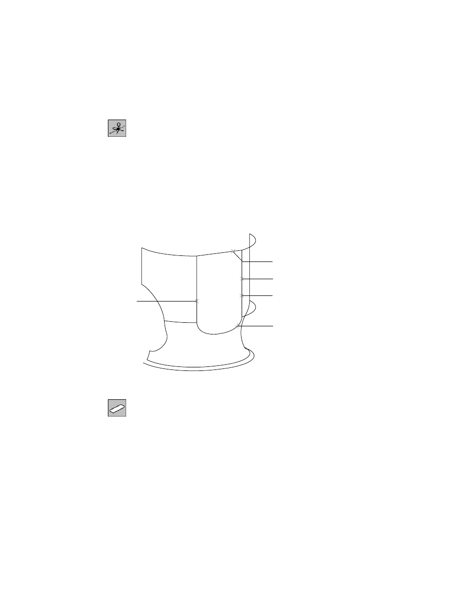
To sweep a surface on two wires and two rails
1
Use
AMSWEEPSF
to create the top B surface, responding to the prompts.
Desktop Menu
Surface ➤ Create Surface ➤ Sweep
Select cross sections:
Select wire (2)
Select cross sections:
Select wire (3) and press
ENTER
Select rails:
Select wire (4)
Select rails:
Select wire (5)
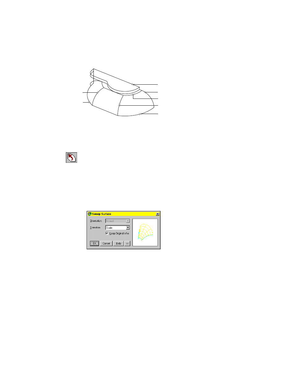
In the Sweep Surface dialog box, specify:
Transition:
Scale
Keep Original Wire:
Check the check box
Choose OK.
1
2
4
3
5
6
7
628
|
Chapter 21
Surfacing Wireframe Models
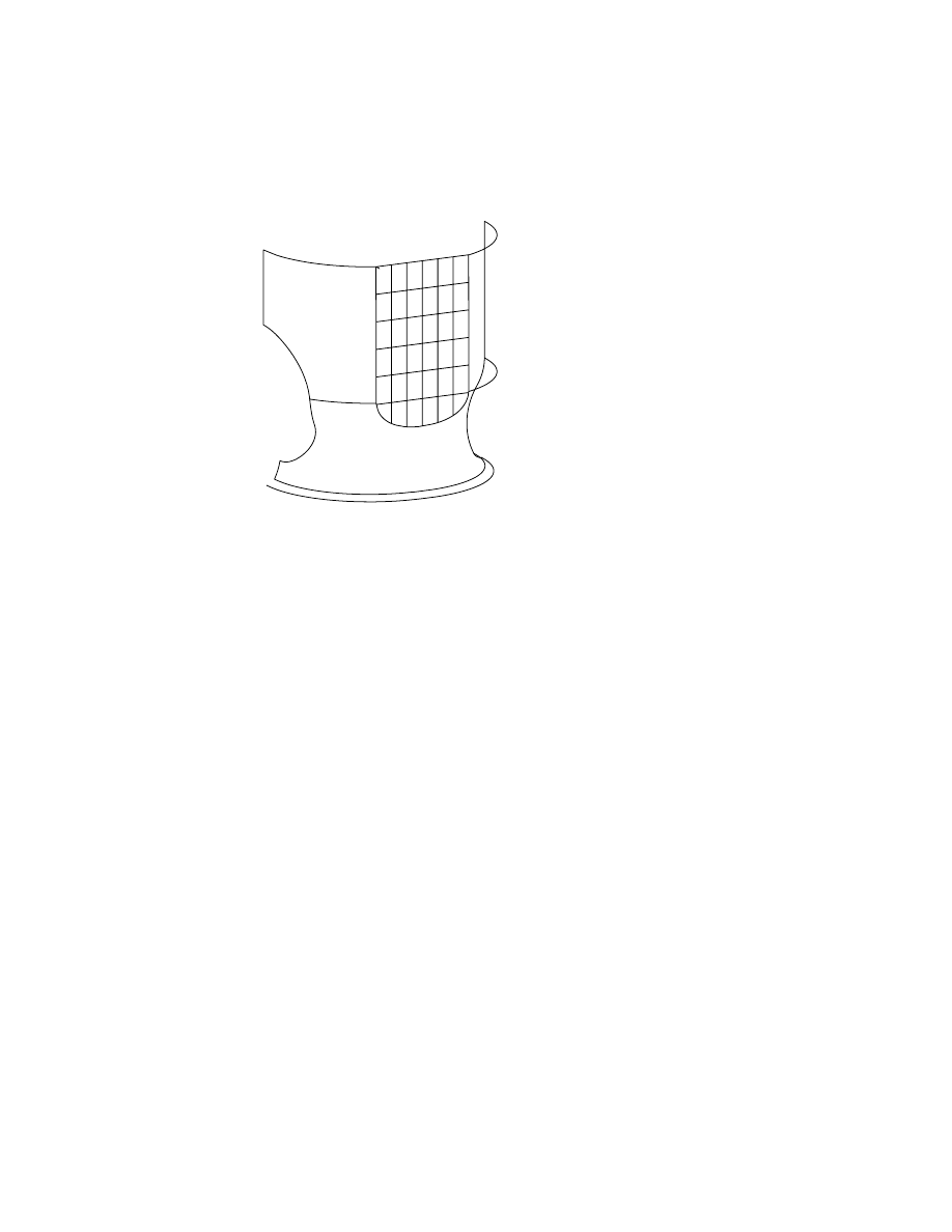
To sweep a surface on one wire and one rail
1
Use
AMSWEEPSF
to create the top C surface, responding to the prompts.
Desktop Menu
Surface ➤ Create Surface ➤ Sweep
Select cross sections:
Select wire (6) and press
ENTER
Select rails:
Select wire (7) and press
ENTER
In the Sweep Surface dialog box, in Orientation select Normal. Choose OK.
The surface extends beyond the far side of the top. You will trim it later.
2
Move surfaces A, B, and C to the
TOP
layer, responding to the prompts.
Command
CHPROP
Select objects:
Select surfaces (A), (B), and (C) and press
ENTER
Enter property to change [Color/LAyer/LType/ltScale/LWeight/Thickness]:
Enter La
Enter new layer name <10>:
Enter top
Enter property to change [Color/LAyer/LType/ltScale/LWeight/Thickness]:
Press
ENTER
The surfaces are now on the
TOP
layer. Because the
TOP
layer is frozen, you
cannot see the surfaces, although the wireframe is still visible.
Save the file.
The D and E surfaces are ruled surfaces.
C
A
B
E
D
Creating Trimmed Planar Surfaces
|
629
To create a ruled surface between wires
1
Use
AMRULE
to create the top D surface, responding to the prompts.
Desktop Menu
Surface ➤ Create Surface ➤ Rule
Select first wire:
Select wire (1)
Select second wire:
Select wire (2)
2
Use
BREAK
to separate line segment (4) from polyline (3), responding to the
prompts.
Desktop Menu
Modify ➤ Break
Select object:
Enter end
of:
Select polyline (3)
Specify second break point or [First point]:
Enter @
Unless you enter @, the adjoining portion of the polyline is deleted. The @ sym-
bol breaks the polyline at the specified location and retains both segments.
3
Use
AMRULE
to create the top E surface, responding to the prompts.
Desktop Menu
Surface ➤ Create Surface ➤ Rule
Select first wire:
Select wire (4)
Select second wire:
Select wire (5)
4
Move the top D and top E surfaces to the
TOP
layer, responding to the
prompts.
Command
CHPROP
Select objects:
Select surface (D)
Select objects:
Select surface (E) and press
ENTER
Enter property to change [Color/LAyer/LType/ltScale/LWeight/Thickness]:
Enter La
Enter new layer name <10>:
Enter top
Enter property to change [Color/LAyer/LType/ltScale/LWeight/Thickness]:
Press
ENTER
Save the file.
3
4
5
2
1
630
|
Chapter 21
Surfacing Wireframe Models
Next, break and join lines that are needed to create the top F planar surface.
To create a planar surface with a joined polyline boundary
1
Use
BREAK
to break polyline (1) where it intersects polyline (2), responding
to the prompts.
Desktop Menu
Modify ➤ Break
Select object:
Select polyline (1)
Specify second break point or [First point]:
Enter f
Specify first break point:
Enter int
of:
Select polyline (2) at the intersection
Specify second break point:
Enter @
To check that the polyline has broken correctly, select it. Grip points should
appear only for the line segment you select. Press
ESC
to exit Grip mode.
The break creates a line segment you use as part of the boundary for the next
surface.
2
Use
AMJOIN3D
to join the polylines that form the boundary of top F.
Desktop Menu
Surface ➤ Edit Wireframe ➤ Join
trimmed planar surface
1
2
Creating Trimmed Planar Surfaces
|
631
3
In the Join3D dialog box, specify:
Mode:
Automatic
Output:
Polyline
Gap Tolerance:
Enter .004
Choose OK.
4
Respond to the prompts as follows:
Select start wire or:
Select polyline (1)
Select wires to join:
Select polylines (2) through (5)
Select wires to join:
Press
ENTER
Reverse direction? [Yes/No] <No>:
Press
ENTER
to accept the direction of the new wire
To confirm that the segments are joined, select the polyline and check the
grip points.
1
2
4
3
5
632
|
Chapter 21
Surfacing Wireframe Models
5
Use
AMPLANE
to create the top F surface from the joined polyline, responding
to the prompt.
Desktop Menu
Surface ➤ Create Surface ➤ Planar Trim
If you use the command line method, enter w at the prompt before continu-
ing to the following prompt.
Select wires:
Select the joined polyline and press
ENTER
You have created the trimmed planar surface. Save the file.
For the top G surface, extrude a polyline along a straight line, and then trim
the surface to the desired shape.
To create a surface with an extruded polyline
1
Change to a front left isometric view.
Desktop Menu
View ➤ 3D Views ➤ Front Left Isometric
2
Us
AMEXTRUDESF
to extrude the polyline (1) down the wire (2), responding
to the prompts.
Desktop Menu
Surface ➤ Create Surface ➤ Extrude
Select wires to extrude:
Select polyline (1) and press
ENTER
Define direction and length.
Specify start point or [Viewdir/Wire/X/Y/Z]:
Enter w
Select wire to define direction:
Select polyline (2)
Enter an option [Accept/Flip] <Accept>:
Enter f to flip the direction arrow down, or press
ENTER
Enter taper angle <0>:
Press
ENTER
to accept the default
2
1
Creating Trimmed Planar Surfaces
|
633
Your selection point determines the extrusion direction. Select a point on
polyline (2) close to polyline (1). If you select a point beyond the midpoint of
polyline (2), the direction of the extrusion is reversed.
Your drawing should look like this.
3
Move top F and top G to the
TOP
layer, responding to the prompts.
Command
CHPROP
Select objects:
Select surface (F)
Select objects:
Select surface (G) and press
ENTER
Enter property to change [Color/LAyer/LType/ltScale/LWeight/Thickness]:
Enter La
Enter new layer name <10>:
Enter top
Enter property to change [Color/LAyer/LType/ltScale/LWeight/Thickness]:
Press
ENTER
4
Choose Assist ➤ Format ➤ Layer.
Thaw the
TOP
layer to see all the surfaces you have created.
5
Use
AMINTERSF
to trim top G and top C at their intersection, responding to
the prompts.
Desktop Menu
Surface ➤ Edit Surface ➤ Intersect Trim
Select first surface/quilt or wire:
Select surface (1)
Select second surface:
Select surface (2)
1
2
634
|
Chapter 21
Surfacing Wireframe Models
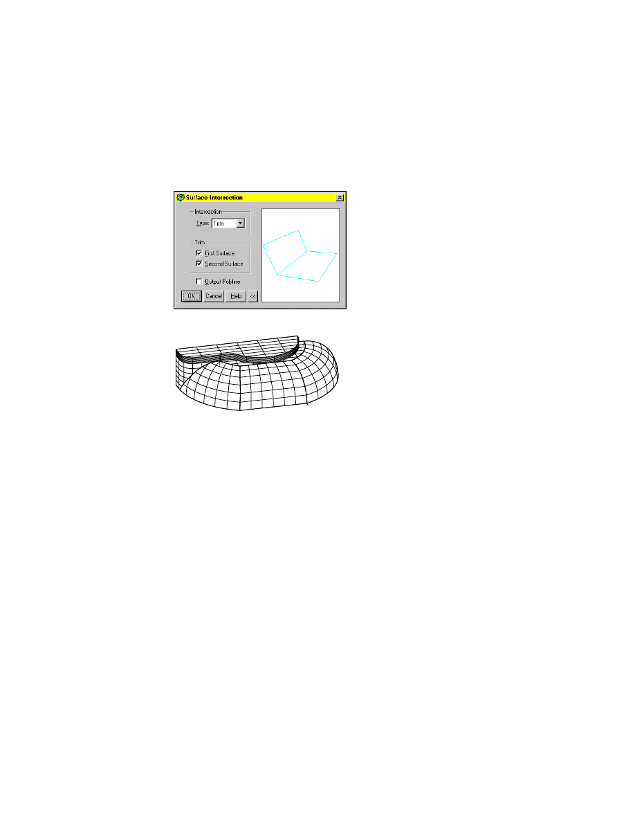
6
In the Surface Intersection dialog box, specify:
Type:
Trim
Trim:
Select both First Surface and Second Surface
Clear the checkbox for Output Polyline
Choose OK. The surfaces are trimmed where they intersect.
Save the file.
Joining Surfaces on Complex Shapes
Next, you surface the inlet portion of the pump. Because the inlet has a com-
plex shape, you will need five surfaces to represent its shape.
■
Inlets A and C are ruled surfaces because they follow two polylines.
■
Inlet B is an extruded surface that is trimmed to its final shape.
■
Inlet D is surface blended to surfaces B, C, and E.
■
Inlet E is a trimmed planar surface created from joined lines that form its
boundary.
Joining Surfaces on Complex Shapes
|
635
NOTE
Be sure to select surfaces and lines where indicated on the illustrations.
To select precisely, zoom in as needed.
To create the inlet A ruled surface
1
From the Desktop menu, choose Assist ➤ Format ➤ Layer.
In the Layer Properties Manager dialog box, thaw layer
20
and make it cur-
rent. Then freeze layer
10
and
TOP
.
2
Change to a right isometric view.
Desktop Menu
View ➤ 3D Views ➤ Front Right Isometric
3
Use
AMRULE
to create the inlet A surface, responding to the prompts.
Desktop Menu
Surface ➤ Create Surface ➤ Rule
Select first wire:
Select wire (1)
Select second wire:
Select wire (2)
The ruled surface is created on the top of the inlet.
inlet E
inlet D
inlet A
inlet B
inlet C
2
1
inlet A
636
|
Chapter 21
Surfacing Wireframe Models
4
Move the inlet A surface to the
INLET
layer, responding to the prompts.
Command
CHPROP
Select objects:
Select inlet A surface and press
ENTER
Enter property to change [Color/LAyer/LType/ltScale/LWeight/Thickness]:
Enter La
Enter new layer name <20>:
Enter inlet
Enter property to change [Color/LAyer/LType/ltScale/LWeight/Thickness]:
Press
ENTER
Inlet B is an extruded partial cylinder, trimmed to its final shape by a closed
wire. The surface is extruded across the inlet wireframe.
The direction of the extrusion is determined by where you select the wire.
You can flip the direction of the extrusion.
Next, you create a ruled surface for inlet B.
NOTE
To select the wires, you might need to reorient the view. Use icons on
the Mechanical View toolbar, or options from the View ➤ 3D Views menu.
To create the inlet B extruded surface
1
Use
AMEXTRUDESF
to extrude polyline (1) along line (2), responding to the
prompts.
Desktop Menu
Surface ➤ Create Surface ➤ Extrude
Select wires to extrude:
Select polyline (1) and press
ENTER
Define direction and length.
Specify start point or [Viewdir/Wire/X/Y/Z]
Enter w
Select wire to define direction:
Select polyline (2) near (1)
Enter an option [Accept/Flip] <Accept>:
Enter f to flip direction arrow into part or press
ENTER
Enter taper angle <0>:
Press
ENTER
2
1
Joining Surfaces on Complex Shapes
|
637
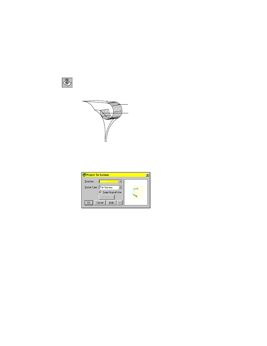
A close look at the inlet reveals that the extruded surface extends beyond the
wireframe. You trim the inlet B surface to the boundary of surface D.
2
Use
AMPROJECT
to project the edge of inlet D to trim the inlet A surface,
responding to the prompts.
Desktop Menu
Surface ➤ Edit Surface ➤ Project Trim
Select wires to project:
Select line (1) and press
ENTER
Select target surfaces/quilts:
Select surface (2) and press
ENTER
3
In the Project to Surface dialog box, specify:
Direction:
Normal
Output type:
Trim surface
Keep Original Wire:
Check the check box
Choose OK.
You have trimmed inlet B by projection, keeping the wire you used to trim
the inlet surface.
Next you create inlet C, a ruled surface between two wires.
1
2
638
|
Chapter 21
Surfacing Wireframe Models
To create the inlet C ruled surface
1
Use
AMRULE
to create the inlet C surface, responding to the prompts.
Desktop Menu
Surface ➤ Create Surface ➤ Rule
Select first wire:
Select wire (1)
Select second wire:
Select wire (2)
Your model should look like this.
2
Use
CHPROP
to move inlet B and C surfaces to the
INLET
layer.
Save the file.
Next, you create inlet D, a surface blended from the edges of inlet B and C
surfaces and the polyline that defines the edge of inlet E. You may need to
rotate the model to show the intersection clearly.
1
2
Joining Surfaces on Complex Shapes
|
639
To create the inlet D blended surface
1
Use
BREAK
to break the polyline into two line segments, responding to the
prompts.
Desktop Menu
Modify ➤ Break
Select object:
Select polyline (1)
Specify second break point or [First point]:
Enter f
Specify first break point:
Enter int
of:
Select polyline (2)
Specify second break point:
Enter @
Check the grip points of the line segments after you break the polyline.
2
Use
AMBLEND
to create the inlet D surface, responding to the prompts.
Desktop Menu
Surface ➤ Create Surface ➤ Blend
Select first wire:
Select wire (1)
Select second wire:
Select wire (2)
Select third wire:
Select wire (3)
Select fourth wire:
Select wire (4)
Make selections in order, selecting opposite wires in pairs.
1
2
2
4
1
3
640
|
Chapter 21
Surfacing Wireframe Models
The blended surface should look like this.
3
Use
CHPROP
to move the surface to the
INLET
layer.
Join the lines to form the boundary of inlet E, and then create a trimmed planar
surface from the joined lines. Zoom in as needed to make line selection easier.
To create the inlet E trimmed planar surface
1
Use
AMJOIN3D
to join selected lines to form the boundary for the inlet E sur-
face.
Desktop Menu
Surface ➤ Edit Wireframe ➤ Join
In the Join3D dialog box, specify:
Mode:
Automatic
Output:
Polyline
Gap Tolerance:
Enter .01
Choose OK.
2
Respond to the prompts as follows:
Select start wire or:
Select polyline (1)
Select wires to join:
Select wires (2) through (4)
Select wires to join:
Press
ENTER
Reverse direction? [Yes/No] <No>:
Press
ENTER
1
2
3
4
Joining Surfaces on Complex Shapes
|
641
This procedure joins lines regardless of their original direction and converts
arcs and splines into polylines. You may need to reset the gap tolerance to
correctly join the polylines.
3
Use
AMPLANE
to create a trimmed planar surface from the joined lines,
responding to the prompts.
Desktop Menu
Surface ➤ Create Surface ➤ Planar Trim
If you choose the command line method, enter w at the prompt before con-
tinuing to the following prompts.
Select wires:
Select polyline (1)
Select wires:
Press
ENTER
Your surface should look like this.
4
Use
CHPROP
to move inlet E to the
INLET
layer.
Now you can trim top D by projecting the edge of the inlet. First, thaw layers
to show the inlet and top sections of the pump. Then, break a polyline into
segments and join one segment with other polylines. The joined polylines
form the shape of the projection that cuts material where the two surfaces
intersect.
To make selection easier, zoom and rotate the view as needed.
642
|
Chapter 21
Surfacing Wireframe Models
To create a shape on a surface using joined wires
1
Thaw layers
10
and
20.
2
Change to the front right isometric view.
Desktop Menu
View ➤ 3D Views ➤ Front Right Isometric
3
Use
BREAK
to break the polyline, responding to the prompts.
Desktop Menu
Modify ➤ Break
Select object:
Select polyline (1)
Specify second break point or [First point]:
Enter f
Specify first break point:
Enter end
of:
Select polyline (2)
Specify second break point:
Enter @
NOTE
Use 3D Orbit and Zoom Realtime to rotate the view and zoom in to
show the lines clearly. If you prefer, use
VPOINT
to set a precise viewpoint. In this
case, set the coordinates 4,-6,1 to show the lines you need for the next step.
4
Break the upper part of the polyline into segments, responding to the
prompts.
Desktop Menu
Modify ➤ Break
Select object:
Select polyline (1)
Specify second break point or [First point]:
Enter f
Specify first break point:
Enter int
of:
Select polyline (2)
Specify second break point:
Enter @
2
1
Joining Surfaces on Complex Shapes
|
643
5
Use
AMJOIN3D
to combine three polyline segments.
Desktop Menu
Surface ➤ Edit Wireframe ➤ Join
In the Join3D dialog box, specify:
Mode:
Automatic
Output:
Polyline
Gap Tolerance:
Enter .004
Choose OK.
6
Respond to the prompts as follows:
Select start wire or:
Select polyline (1)
Select wires to join:
Select wire (2)
Select wires to join:
Select wire (3) and press
ENTER
Reverse direction? [Yes/No] <No>:
Press
ENTER
The segments are joined together. Later, you will project the joined line onto
the top surface.
1
2
3
2
1
644
|
Chapter 21
Surfacing Wireframe Models
To trim a surface using a projected wire shape
1
Freeze layer
10
and thaw the
TOP
layer.
2
Return to the front right isometric view.
Desktop Menu
View ➤ 3D Views ➤ Front Right Isometric
3
Use
AMPROJECT
to cut top B where the inlet fits, responding to the prompts.
Desktop Menu
Surface ➤ Edit Surface ➤ Project Trim
Select wires to project:
Select wire (1) and press
ENTER
Select target surfaces/quilts:
Select surface (2) and press
ENTER
4
In the Project to Surface dialog box, specify:
Direction:
Normal
Output Type:
Trim Surface
Keep Original Wires:
Remove the check from the check box
Choose OK.
Top B is cut open for the inlet. The top and inlet are complete. Save the file.
1
2
Creating Swept and Projected Surfaces
|
645
Creating Swept and Projected Surfaces
For the main body of the pump, you continue building and trimming sur-
faces to their correct shapes.
■
Body A, B, and C are swept surfaces created from curves and rails.
■
Body D is a surface created from the boundaries of Body A, B, and C
surfaces.
To create the body A, B, and C swept surfaces
1
Thaw layer
30
and make it current. Freeze layers
10
,
20,
and
TOP
.
2
Use
AMSWEEPSF
to create the body A surface on the right side of the model.
Desktop Menu
Surface ➤ Create Surface ➤ Sweep
body A
body C
body B
body D
646
|
Chapter 21
Surfacing Wireframe Models
Respond to the prompts:
Select cross sections:
Select wire (1)
Select cross sections:
Select wire (2) and press
ENTER
Select rails:
Select wire (3)
Select rails:
Select wire (4)
3
In the Sweep Surface dialog box, specify:
Transition:
Scale
Keep Original Wires:
Check the check box
Choose OK
4
Use
AMSWEEPSF
to create the body B surface on the left side of the model,
responding to the prompts.
Desktop Menu
Surface ➤ Create Surface ➤ Sweep
NOTE
To repeat the previous command, press
ENTER
or the
SPACEBAR
.
Select cross sections:
Select wire (5) and press
ENTER
Select rails:
Select wire (6) and press
ENTER
1
3
4
2
8
5
6
7
Creating Swept and Projected Surfaces
|
647
5
In the Sweep Surface dialog box, under Orientation, specify Normal. Leave
Keep Original Wires checked, and choose OK.
6
Create the body C surface near the bottom of the model, responding to the
prompts.
Desktop Menu
Surface ➤ Create Surface ➤ Sweep
Select cross sections:
Select wire (7) and press
ENTER
Select rails:
Select the wire (8) and press
ENTER
7
In the Sweep Surface dialog box, under Orientation, specify Normal. Verify
that Keep Original Wires is checked, and choose OK.
Your model should look like this.
8
Thaw layer
20
to reveal the inlet wires.
648
|
Chapter 21
Surfacing Wireframe Models
To trim a surface with a projection wire
1
Use
AMPROJECT
to trim the body surface with the inlet edge, responding to
the prompts.
Desktop Menu
Surface ➤ Edit Surface ➤ Project Trim
Select wires to project:
Select wire (1)
Select wires to project:
Press
ENTER
Select target surfaces/quilts:
Select surface (2)
Select target surfaces/quilts:
Press
ENTER
2
In the Project to Surface dialog box, specify:
Direction:
Normal
Output Type:
Trim Surface
Verify that Keep Original Wires is checked, and choose OK.
The projected wire cut away a portion of body A surface, but the wire was not
deleted.
1
2
Creating Swept and Projected Surfaces
|
649
3
Freeze layer
20
.
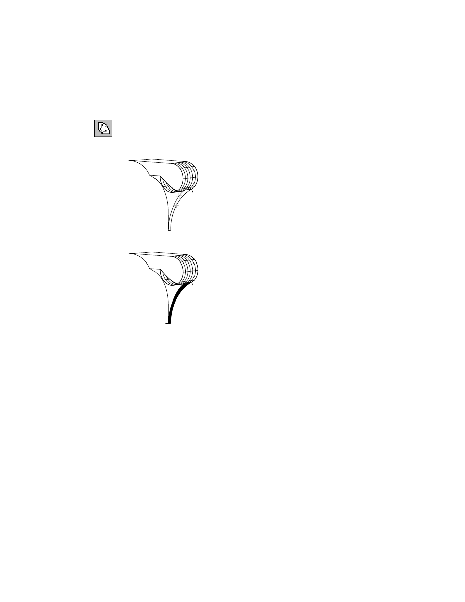
Cut out the surface areas on body C where body D and the outlet (to be sur-
faced later) extend onto body C.
body surface removed
650
|
Chapter 21
Surfacing Wireframe Models
To trim the body C surface with projection wires
1
Change to the front view of your model.
Desktop Menu
View ➤ 3D Views ➤ Front
2
Trim Body C with the lower curve of the flat surface (1), responding to the
prompts.
Desktop Menu
Surface ➤ Edit Surface ➤ Project Trim
Select wires to project:
Select wire (1)
Select wires to project:
Press
ENTER
Select target surfaces/quilts:
Select surface (2)
Select target surfaces/quilts:
Press
ENTER
3
In the Project to Surface dialog box, specify:
Direction:
Normal
Output Type:
Trim Surface
Verify that Keep Original Wires is checked, and choose OK.
1
2
Creating Swept and Projected Surfaces
|
651
Your model should look like this.
4
Change to the front left isometric view.
Desktop Menu
View ➤ 3D Views ➤ Front Left Isometric
NOTE
To set the viewpoint precisely, use
VPOINT
to specify coordinates. For
example, this viewpoint is -5,-10,3.
5
Trim the body B surface with the curve that defines the upper edge of the out-
let. Repeating steps 2 and 3, project wire 3 onto surface 4.
4
3
5
6
652
|
Chapter 21
Surfacing Wireframe Models
6
Trim body C with the curve that defines the lower edge of the outlet,
responding to the prompts.
Desktop Menu
Surface ➤ Edit Surface ➤ Project Trim
Select wires to project:
Select wire
Select wires to project:
Press
ENTER
Select target surfaces/quilts:
Select surface (6)
Select target surfaces/quilts:
Press
ENTER
7
In the Project to Surface dialog box, specify:
Direction:
Normal
Output Type:
Trim Surface
Verify that Keep Original Wires is checked, and choose OK.
Your model should look like this.
8
Use
CHPROP
to move surfaces A, B, and C to the
BODY
layer.
Next, you edit the wireframe to join the lines that form the boundary of body
D. You use the polyline to create a planar surface.
Before you begin, set
DELOBJ
to delete original objects.
Toolbutton
On the Surfacing toolbar, use the
DELOBJ
toolbutton to set
delete original objects.
Creating Swept and Projected Surfaces
|
653
To create the body D planar surface
1
Use
AMJOIN3D
to join the polylines that define the boundary of body D.
Desktop Menu
Surface ➤ Edit Wireframe ➤ Join
In the Join 3D dialog box, specify:
Mode:
Automatic
Output:
Polyline
Choose OK.
2
Respond to the prompts as follows:
Select start wire or:
Select the wire (1)
Select wires to join:
Select wires (2), (3), and (4)
Select wires to join:
Press
ENTER
Reverse direction? [Yes/No] <No>:
Press
ENTER
3
Use
AMPLANE
to create a planar surface from the joined line, responding to
the prompts.
Desktop Menu
Surface ➤ Create Surface ➤ Planar
Specify first corner or [Plane/Wires]:
Enter w
Select wires:
Select wire (5) and press
ENTER
1
2
3
4
5
654
|
Chapter 21
Surfacing Wireframe Models
Your model should look like this.
4
Use
CHPROP
to move body D to the
BODY
layer. Save the file.
The pump body surfaces are complete.
Creating Complex Swept Surfaces
|
655
Creating Complex Swept Surfaces
Next, you create the surfaces for the outlet on the side of the pump.
Outlet A is a swept surface that blends dissimilar cross sections.
To create the outlet A swept surface
1
Thaw layer
40
and make it current, and then freeze all other layers.
2
Change to the left isometric view to make lines easier to select.
Desktop Menu
View ➤ 3D Views ➤ Front Left Isometric
3
Use
AMSWEEPSF
to Sweep three cross sections along two rails, responding to
the prompts.
Desktop Menu
Surface ➤ Create Surface ➤ Sweep
Select cross sections:
Select wires (1), (2), and (3)
Select rails:
Select wires (4) and (5)
outlet F
(back side)
outlet E
outlet C
outlet A
outlet B
outlet D
1
2
3
4
5
656
|
Chapter 21
Surfacing Wireframe Models
4
In the Sweep Surface dialog box, in Transition, specify Scale. Choose OK.
Outlet A should look like this.
5
Use
CHPROP
to move outlet A to the
OUTLET
layer.
Next create a ruled surface for outlet B. The difference between this surface
and the one you just completed is that outlet A is curved in two directions,
and outlet B is curved in one direction and flat in the other.
To create the outlet B ruled surface
1
Use
AMRULE
to create the outlet B surface, responding to the prompts.
Desktop Menu
Surface ➤ Create Surface ➤ Rule
Select first wire:
Select wire (1)
Select second wire:
Select wire (2)
1
2
Creating Complex Swept Surfaces
|
657
Outlet B should look like this.
2
Use
CHPROP
to move outlet B to the
OUTLET
layer.
Next, you create another swept surface and another ruled surface.
To create the outlet C and outlet D surfaces
1
To make selections easier, rotate the model to the left with the Desktop View
icons, or set specific coordinates (6,-8,1) with
VPOINT
, responding to the
prompts.
Desktop Menu
View ➤ 3D Views ➤
VPOINT
Current view direction: VIEWDIR=-1.0000,-1.0000,1.0000
Specify a view point or [Rotate] <display compass and tripod>:
Enter 6,-8,1
2
Use
AMSWEEPSF
to create outlet C swept surface.
Desktop Menu
Surface ➤ Create Surface ➤ Sweep
658
|
Chapter 21
Surfacing Wireframe Models
Respond to the prompts:
Select cross sections:
Select wire (1)
Select cross sections:
Select wire (2) and press
ENTER
Select rails:
Select wire (3)
Select rails:
Select wire (4)
3
In the Sweep Surface dialog box, under Transition, specify Scale. Choose OK.
4
Use
AMRULE
to create outlet D ruled surface, responding to the prompts.
Desktop Menu
Surface ➤ Create Surface ➤ Rule
Select first wire:
Select wire (5)
Select second wire:
Select wire (6)
Your model should look like this.
5
Use
CHPROP
to move both of the surfaces to the
OUTLET
layer.
Next, you join lines to form the boundaries of outlet E and outlet F. From the
newly created polyline, you create planar surfaces for the outlet.
4
2
3
5
6
1
3
Creating Complex Swept Surfaces
|
659
To create the outlet E planar surface
1
Use
AMJOIN3D
to join the polylines.
Desktop Menu
Surface ➤ Edit Wireframe ➤ Join
In the Join3D dialog box, specify:
Mode:
Automatic
Output:
Polyline
Choose OK.
2
Select the polylines, responding to the prompts.
Select start wire or:
Select wire (1)
Select wires to join:
Select wires (2), (3), and (4), and press
ENTER
Reverse direction? [Yes/No] <No>:
Press
ENTER
to accept the join direction
3
Use
AMPLANE
to create the outlet E surface from the joined polyline, respond-
ing to the prompts.
Desktop Menu
Surface ➤ Create Surface ➤ Planar
Specify first corner or [Plane/Wires]:
Enter w
Select wires:
Select wire (1) and press
ENTER
To create the outlet F planar surface
1
Use
AMJOIN3D
to combine lines that form the boundary for outlet F.
Desktop Menu
Surface ➤ Edit Wireframe ➤ Join
In the Join 3D dialog box, specify:
Mode:
Manual
Output type:
Polyline
Choose OK.
3
2
1
4
6
5
660
|
Chapter 21
Surfacing Wireframe Models
2
Select the polylines to join, responding to the prompts.
Select start wire or:
Select wire (5)
Select wires to join:
Select wire (6) and press
ENTER
Reverse direction? [Yes/No] <No>:
Press
ENTER
to accept the join direction
NOTE
Use the Manual mode to join lines even if they are far apart. It joins all
the lines you select in the order you choose them.
3
Use
AMPLANE
to create outlet F from the lines you just joined, responding to
the prompts.
Desktop Menu
Surface ➤ Create Surface ➤ Planar
Specify first corner or [Plane/Wires]:
Enter w
Select wires:
Select wire (6) and press
ENTER
Your model should look like this.
4
Use
CHPROP
to move the surfaces to the
OUTLET
layer.
Save the file.
Using Projection to Create Surfaces
|
661
Using Projection to Create Surfaces
Next, you use projection to create ruled and planar surfaces for the base of
the pump.
To create the base A surface
1
Thaw layer
50
and make it current. Then freeze all other layers.
2
Change to the left front isometric view.
Desktop Menu
View ➤ 3D Views ➤ Front Right Isometric
3
Use
AMRULE
to create the base A surface, responding to the prompts.
Desktop Menu
Surface ➤ Create Surface ➤ Rule
Select first wire:
Select wire (1)
Select second wire:
Select wire (2)
base A
base B
base C
1
2
662
|
Chapter 21
Surfacing Wireframe Models
The illustration shows the ruled surface fit to the flat areas and corner curves.
4
Use
CHPROP
to move base A to the
BASE
layer.
Next, you join the lines needed to create a planar surface on the bottom of
the pump. Then you copy the surface and trim it.
To create the base B and C surfaces
1
Use
AMJOIN3D
to create a polyline from two wires.
Desktop Menu
Surface ➤ Edit Wireframe ➤ Join
In the Join3D dialog box, specify:
Mode:
Automatic
Output:
Polyline
Choose OK.
2
Select the wires, responding to the prompts:
Select start wire or:
Select wire (1)
Select wires to join:
Select wire (2) and press
ENTER
Reverse direction? [Yes/No] <No>:
Press
ENTER
1
2
Using Projection to Create Surfaces
|
663
3
Create a planar surface on the bottom of the base, responding to the
prompts.
Desktop Menu
Surface ➤ Create Surface ➤ Planar
Specify first corner or [Plane/Wires]:
Enter w
Select wires:
Select wire (1) and press
ENTER
The planar surface is created.
4
Use
COPY
to copy the last surface, responding to the prompts.
Desktop Menu
Modify ➤ Copy
Select objects:
Select surface (1) and press
ENTER
Specify base point or displacement, or [Multiple]:
Enter end
of:
Select point (2)
Specify second point of displacement or <use first point as displacement>:
Enter end
of:
Select point (3)
Next, project a wire onto the base C surface to trim it.
1
3
2
664
|
Chapter 21
Surfacing Wireframe Models
To trim the base C surface
1
Use
CHPROP
to move the bottom surface to the
BASE
layer.
2
Project the curve of the body onto the top surface of the base, responding to
the prompts.
Desktop Menu
Surface ➤ Edit Surface ➤ Project Trim
Select wires to project:
Select polyline (1) and press
ENTER
Select target surfaces/quilts:
Select surface (2) and press
ENTER
3
In the Project to Surface dialog box, specify:
Direction:
Normal
Output type:
Trim Surface
Choose OK.
Your model should look like this.
4
Use
CHPROP
to move the surfaces to the
BASE
layer.
Save the file.
1
2
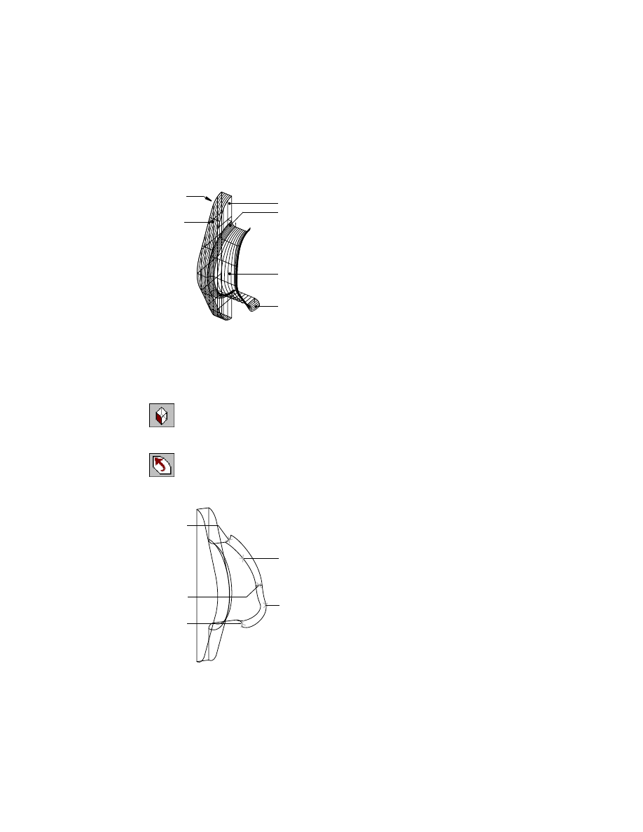
Using Advanced Surfacing Techniques
|
665
Using Advanced Surfacing Techniques
Next, you create the support rib from the surfaces. Using the techniques you
have already learned, surface the support rib from these general instructions.
Save a copy of your drawing before you begin working on your own.
To create the support rib
1
Thaw layer
60
.
2
Create a ruled surface on the left side of the support rib (rib A).
3
Create a ruled surface on the right side of the support rib (rib B).
4
Move the surfaces to the
SUPPORT_RIB
layer.
5
Create a swept surface for rib C.
6
Move the surface to the
SUPPORT_RIB
layer.
7
Add the support rib to the body and base surfaces.
If you need to, follow these specific instructions to create the support rib.
rib C
rib B
rib A
666
|
Chapter 21
Surfacing Wireframe Models
To create the rib A and rib B surfaces
1
Thaw layer
60
and make it current. Then freeze all other layers.
2
Use
AMRULE
to create a ruled surface on the left side of the support rib,
responding to the prompts.
Desktop Menu
Surface ➤ Create Surface ➤ Rule
Select first wire:
Select wire (1)
Select second wire:
Select wire (2)
3
Create a ruled surface on the right side of the support rib, responding to the
prompts.
Desktop Menu
Surface ➤ Create Surface ➤ Rule
Select first wire:
Select wire (3)
Select second wire:
Select wire (4)
The surfaces should look like this.
4
Use
CHPROP
to move the surfaces to the
SUPPORT_RIB
layer.
1
2
3
4
Using Advanced Surfacing Techniques
|
667
To create the rib C surface
1
Use
AMSWEEPSF
to create the rib C surface, responding to the prompts.
Desktop Menu
Surface ➤ Create Surface ➤ Sweep
Select cross sections:
Select wire (1) and (2)
Select cross sections:
Press
ENTER
Select rails:
Select wires (3) and (4)
2
In the Sweep Surface dialog box, under Transition, specify Scale. Choose OK.
Your surface should look like this.
3
Move the surface to the
SUPPORT_RIB
layer.
4
Use
AMJOIN3D
to join the lines defining the boundary of the support rib.
Desktop Menu
Surface ➤ Edit Wireframe ➤ Join
5
In the Join3D dialog box, specify:
Mode:
Automatic
Output:
Polyline
Choose OK.
6
Select the lines.
Select start wire or:
Select wire (1)
Select wires to join:
Select wires (2), (3), and (4), and then press
ENTER
Reverse direction? [Yes/No] <No>:
Press
ENTER
The support rib wires are joined and ready to project onto the pump.
1
4
2
3
1
4
2
3
668
|
Chapter 21
Surfacing Wireframe Models
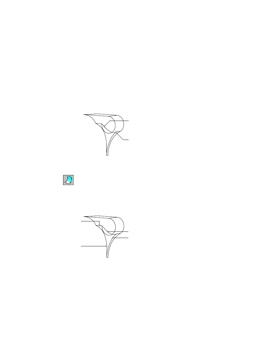
To add the support rib
1
Thaw the
BODY
and
BASE
layers.
2
Use
AMPROJECT
to project the support rib onto the pump, responding to the
prompts.
Desktop Menu
Surface ➤ Edit Surface ➤ Project Trim
Select wires to project:
Select wire (1) and press
ENTER
Select target surfaces/quilts:
Select surface (2)
Select target surfaces/quilts:
Select surface (3) and press
ENTER
3
In the Project to Surface dialog box, specify:
Direction:
Normal
Output:
Trim Surface
Choose OK.
The support rib is projected onto the body and the base.
Save your file.
3
2
1
body surface removed
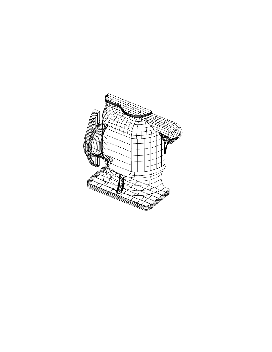
Viewing Completed Surfaced Models
|
669
Viewing Completed Surfaced Models
To view the completed model, freeze all layers except
BASE, BODY, INLET,
OUTLET, SUPPORT_RIB
, and
TOP
.
Use the Zoom Extents option of
ZOOM
to view the entire wireframe model.
One half of the pump housing is complete. You can mirror the surfaces to cre-
ate a complete model.

670
Wyszukiwarka
Podobne podstrony:
Airbus Catia V5 Training Wireframe and Surface
surfacefinishmetrologyiss1 140102202845 phpapp01
Ch21 pg655 690
Dance, Shield Modelling of sound ®elds in enclosed spaces with absorbent room surfaces
Autonomic Nerve (Palmar Surface) tapeSP
Akumulator do BOMBARDIER ROTAX All models Yeti BR All models
Cell surface in the interaction Nieznany
1998 Bustillo Surface Micromach Nieznany (2)
Ch18 Assemble Complex Models
07 2002 Koukitu Surface polarity GaN
Programmed repair Auxiliary heater Part C Models 124, 126 020 024 025
Akumulator do HURLIMANN XB models XB models
fta m5 economic models PRELIMINARY
0400 Function description B Operating principle with function diagram Auxiliary heater Models 124,
env writing models
Akumulator do DRABANT Forest machines all models Forest machine
Akumulator do BRAY Hydraloader P TVO all models Hydraloader P T
więcej podobnych podstron