
Copyright © 2007-2008, 2011 ARM. All rights reserved.
ARM DUI 0379C (ID061811)
ARM
®
Compiler toolchain v4.1 for
µVision
Using the Assembler

ARM DUI 0379C
Copyright © 2007-2008, 2011 ARM. All rights reserved.
ii
ID061811
Non-Confidential
ARM Compiler toolchain v4.1 for µVision
Using the Assembler
Copyright © 2007-2008, 2011 ARM. All rights reserved.
Release Information
The following changes have been made to this book.
Proprietary Notice
Words and logos marked with or are registered trademarks or trademarks of ARM in the EU and other countries, except
as otherwise stated below in this proprietary notice. Other brands and names mentioned herein may be the trademarks
of their respective owners.
Neither the whole nor any part of the information contained in, or the product described in, this document may be
adapted or reproduced in any material form except with the prior written permission of the copyright holder.
The product described in this document is subject to continuous developments and improvements. All particulars of the
product and its use contained in this document are given by ARM in good faith. However, all warranties implied or
expressed, including but not limited to implied warranties of merchantability, or fitness for purpose, are excluded.
This document is intended only to assist the reader in the use of the product. ARM shall not be liable for any loss or
damage arising from the use of any information in this document, or any error or omission in such information, or any
incorrect use of the product.
Where the term ARM is used it means “ARM or any of its subsidiaries as appropriate”.
Confidentiality Status
This document is Non-Confidential. The right to use, copy and disclose this document may be subject to license
restrictions in accordance with the terms of the agreement entered into by ARM and the party that ARM delivered this
document to.
Product Status
The information in this document is final, that is for a developed product.
Web Address
http://www.arm.com
Change History
Date
Issue
Confidentiality
Change
May 2007
A
Non Confidential
Release for RVCT v3.1 for µVision
December 2008
B
Non Confidential
Release for RVCT v4.0 for µVision
June 2011
C
Non Confidential
Release for ARM Compiler toolchain v4.1 for
µVision

ARM DUI 0379C
Copyright © 2007-2008, 2011 ARM. All rights reserved.
iii
ID061811
Non-Confidential
Contents
ARM Compiler toolchain v4.1 for µVision Using the
Assembler
Directives that can be omitted in pass 2 of the assembler ...................................... 2-6
Overview of the ARM Architecture
Changing between ARM, Thumb, and ThumbEE state ........................................... 3-4
Processor modes, and privileged and unprivileged software execution .................. 3-5
Processor modes in ARMv6-M and ARMv7-M ....................................................... 3-6

Contents
ARM DUI 0379C
Copyright © 2007-2008, 2011 ARM. All rights reserved.
iv
ID061811
Non-Confidential
Structure of Assembly Language Modules
An example ARM assembly language module ........................................................ 4-6
Load immediate 32-bit values to a register using LDR Rd, =const ........................ 5-10
Load and store multiple instructions available in ARM and Thumb ....................... 5-21
Specify command line options with an environment variable .................................. 7-6

Contents
ARM DUI 0379C
Copyright © 2007-2008, 2011 ARM. All rights reserved.
v
ID061811
Non-Confidential
Symbols, Literals, Expressions, and Operators
Difference between operator precedence in armasm and C ................................. 8-30

Contents
ARM DUI 0379C
Copyright © 2007-2008, 2011 ARM. All rights reserved.
vi
ID061811
Non-Confidential

ARM DUI 0379C
Copyright © 2007-2008, 2011 ARM. All rights reserved.
1-1
ID061811
Non-Confidential
Chapter 1
Conventions and feedback
The following describes the typographical conventions and how to give feedback:
Typographical conventions
The following typographical conventions are used:
monospace
Denotes text that can be entered at the keyboard, such as commands,
file and program names, and source code.
monospace
Denotes a permitted abbreviation for a command or option. The
underlined text can be entered instead of the full command or option
name.
monospace italic
Denotes arguments to commands and functions where the argument is
to be replaced by a specific value.
monospace bold
Denotes language keywords when used outside example code.
italic
Highlights important notes, introduces special terminology, denotes
internal cross-references, and citations.
bold
Highlights interface elements, such as menu names. Also used for
emphasis in descriptive lists, where appropriate, and for ARM
®
processor signal names.
Feedback on this product
If you have any comments and suggestions about this product, contact your
supplier and give:
•
your name and company

Conventions and feedback
ARM DUI 0379C
Copyright © 2007-2008, 2011 ARM. All rights reserved.
1-2
ID061811
Non-Confidential
•
the serial number of the product
•
details of the release you are using
•
details of the platform you are using, such as the hardware platform,
operating system type and version
•
a small standalone sample of code that reproduces the problem
•
a clear explanation of what you expected to happen, and what actually
happened
•
the commands you used, including any command-line options
•
sample output illustrating the problem
•
the version string of the tools, including the version number and build
numbers.
Feedback on content
If you have comments on content then send an e-mail to
errata@arm.com
. Give:
•
the title
•
the number, ARM DUI 0379C
•
if viewing online, the topic names to which your comments apply
•
if viewing a PDF version of a document, the page numbers to which your
comments apply
•
a concise explanation of your comments.
ARM also welcomes general suggestions for additions and improvements.
ARM periodically provides updates and corrections to its documentation on the ARM
Information Center, together with knowledge articles and Frequently Asked Questions (FAQs).
Other information
•
ARM Product Manuals,
http://www.keil.com/support/man_arm.htm
•
Keil Support Knowledgebase,
http://www.keil.com/support/knowledgebase.asp
•
Keil Product Support,
http://www.keil.com/support/
•
ARM Glossary,
http://infocenter.arm.com/help/topic/com.arm.doc.aeg0014-/index.html
.

ARM DUI 0379C
Copyright © 2007-2008, 2011 ARM. All rights reserved.
2-1
ID061811
Non-Confidential
Chapter 2
Overview of the Assembler
The following topics introduce the assemblers provided with ARM
®
Compiler toolchain:
•
About the ARM Compiler toolchain assemblers on page 2-2
•
Key features of the assembler on page 2-3
•
How the assembler works on page 2-4
•
Directives that can be omitted in pass 2 of the assembler on page 2-6
.

Overview of the Assembler
ARM DUI 0379C
Copyright © 2007-2008, 2011 ARM. All rights reserved.
2-2
ID061811
Non-Confidential
2.1
About the ARM Compiler toolchain assemblers
ARM Compiler toolchain provides:
•
A freestanding assembler,
armasm
.
•
An optimizing inline assembler and a non-optimizing embedded assembler built into the
C and C++ compilers. These use the same syntax for assembly instructions.
2.1.1
See also
Concepts
Using the Compiler:
•
Chapter 7 Using the Inline and Embedded Assemblers of the ARM Compiler
Migration and Compatibility:
•
Chapter 2 Migrating from RVCT v4.0 for µVision to ARM Compiler v4.1 for µVision
•
Chapter 3 Migrating from RVCT v3.1 for µVision to RVCT v4.0 for µVision
.

Overview of the Assembler
ARM DUI 0379C
Copyright © 2007-2008, 2011 ARM. All rights reserved.
2-3
ID061811
Non-Confidential
2.2
Key features of the assembler
The ARM
®
assembler supports:
•
Unified Assembly Language (UAL) for both ARM and Thumb
®
code
•
Vector Floating Point (VFP) instructions in ARM and Thumb code
•
directives in assembly source code
•
processing of user defined macros.
2.2.1
See also
Concepts
•
How the assembler works on page 2-4
•
Unified Assembler Language on page 5-3
•
•
Architecture support for VFP on page 9-3
.
Reference
Assembler Reference:
•
•
Chapter 5 Directives Reference
.

Overview of the Assembler
ARM DUI 0379C
Copyright © 2007-2008, 2011 ARM. All rights reserved.
2-4
ID061811
Non-Confidential
2.3
How the assembler works
The ARM assembler is a 2 pass assembler that outputs object code from the assembly language
source code. This means that it reads the source code twice. Each read of the source code is
called a pass.
This is because assembly language source code often contains forward references. A forward
reference occurs when a label is used as an operand, for example as a branch target, earlier in
the code than the definition of the label.The assembler cannot know the address of the forward
reference label until it reads the definition of the label. During each pass, the assembler performs
different functions.
During the first pass, the assembler:
•
Checks the syntax of the instruction or directive. It faults if there is an error in the syntax,
for example if a label is specified on a directive that does not accept one.
•
Determines the size of the instruction and data being assembled and reserves space.
•
Determines offset of labels within sections.
•
Creates a symbol table containing label definitions and their memory addresses.
During the second pass, the assembler:
•
Faults if an undefined reference is specified in an instruction operand or directive.
•
Encodes the instructions using the label offsets from pass 1, where applicable.
•
Generates relocations.
•
Generates debug information if requested.
•
Outputs the object file.
Memory addresses of labels are determined and finalized in the first pass. Therefore, the
assembly code must not change during the second pass. All instructions must be seen in both
passes. Therefore you must not define a symbol after a
:DEF:
test for the symbol. The assembler
faults if it sees code in pass 2 that was not seen in pass 1.
shows that
num EQU 42
is
not seen in pass 1 but is seen in pass 2.
Example 2-1 Line not seen in pass 1
AREA
x,CODE
[ :DEF: foo
num EQU 42
]
foo DCD num
END
Assembling the code in
A1903E: Line not seen in first pass; cannot be assembled.
shows that
MOV r1,r2
is seen in pass 1 but not in pass 2.

Overview of the Assembler
ARM DUI 0379C
Copyright © 2007-2008, 2011 ARM. All rights reserved.
2-5
ID061811
Non-Confidential
Example 2-2 Line not seen in pass 2
AREA
x,CODE
[ :LNOT: :DEF: foo
MOV r1, r2
]
foo MOV r3, r4
END
Assembling the code in
A1909E: Line not seen in second pass; cannot be assembled.
2.3.1
See also
Concepts
•
2 pass assembler diagnostics on page 7-20
•
Instruction and directive relocations on page 5-34
Reference
Assembler Reference:
•
--diag_error=tag{, tag} on page 2-9
•

Overview of the Assembler
ARM DUI 0379C
Copyright © 2007-2008, 2011 ARM. All rights reserved.
2-6
ID061811
Non-Confidential
2.4
Directives that can be omitted in pass 2 of the assembler
Most directives must appear in both passes of the assembly process. There are a number of
directives that can be omitted from pass 2, but doing this is strongly discouraged. Directives that
can be omitted from pass 2 are:
•
GBLA
,
GBLL
,
GBLS
•
LCLA
,
LCLL
,
LCLS
•
SETA
,
SETL
,
SETS
•
RN
,
RLIST
•
CN
,
CP
•
SN
,
DN
,
QN
•
EQU
•
MAP
,
FIELD
•
GET
,
INCLUDE
•
IF
,
ELSE
,
ELIF
,
ENDIF
•
WHILE
,
WEND
•
ASSERT
•
ATTR
•
COMMON
•
EXORTAS
•
IMPORT
•
EXTERN
•
KEEP
•
MACRO
,
MEND
,
MEXIT
•
REQUIRE8
•
PRESERVE8.
Note
Macros that appear only in pass 1 and not in pass 2 must contain only the above directives.
For example, the code in
assembles without error although the
ASSERT
directive
does not appear in pass 2.
Example 2-3 ASSERT directive appears in pass 1 only
AREA ||.text||,CODE
x EQU 42
IF :LNOT: :DEF: sym
ASSERT x == 42
ENDIF
sym EQU 1
END
Directives that appear in pass 2 but do not appear in pass 1 cause an assembly error. However,
this does not cause an assembly error when using the
ELSE
and
ELIF
directives if their matching
IF
directive appears in pass 1.
assembles without error because the IF
directive appears in pass 1.

Overview of the Assembler
ARM DUI 0379C
Copyright © 2007-2008, 2011 ARM. All rights reserved.
2-7
ID061811
Non-Confidential
Example 2-4 Use of ELSE and ELIF directives
AREA ||.text||,CODE
x EQU
42
IF :DEF: sym
ELSE
ASSERT x == 42
ENDIF
sym EQU 1
END

ARM DUI 0379C
Copyright © 2007-2008, 2011 ARM. All rights reserved.
3-1
ID061811
Non-Confidential
Chapter 3
Overview of the ARM Architecture
The following topics give an overview of the ARM architecture:
•
About the ARM architecture on page 3-2
•
ARM, Thumb, and ThumbEE instruction sets on page 3-3
•
Changing between ARM, Thumb, and ThumbEE state on page 3-4
•
Processor modes, and privileged and unprivileged software execution on page 3-5
•
Processor modes in ARMv6-M and ARMv7-M on page 3-6
•
•
•
General-purpose registers on page 3-10
•
Register accesses on page 3-11
•
Predeclared core register names on page 3-12
•
Predeclared extension register names on page 3-13
•
Predeclared coprocessor names on page 3-14
•
•
Application Program Status Register on page 3-16
•
•
Current Program Status Register on page 3-18
•
Saved Program Status Registers (SPSRs) on page 3-19
•
Instruction set overview on page 3-20
•
Media processing instructions on page 3-22
•

Overview of the ARM Architecture
ARM DUI 0379C
Copyright © 2007-2008, 2011 ARM. All rights reserved.
3-2
ID061811
Non-Confidential
3.1
About the ARM architecture
ARM processors are typical of RISC processors in that they implement a load and store
architecture. Only load and store instructions can access memory. Data processing instructions
operate on register contents only.
It is assumed that you are using a processor that implements the ARMv4 or later architecture.
All these processors have a 32-bit addressing range.
3.1.1
See also
Reference
•
ARM Architecture Reference Manual,
http://infocenter.arm.com/help/topic/com.arm.doc.subset.arch.reference/index.html.

Overview of the ARM Architecture
ARM DUI 0379C
Copyright © 2007-2008, 2011 ARM. All rights reserved.
3-3
ID061811
Non-Confidential
3.2
ARM, Thumb, and ThumbEE instruction sets
The ARM instruction set is a set of 32-bit instructions providing a comprehensive range of
operations.
ARMv4T and later define a 16-bit instruction set called the Thumb instruction set. Most of the
functionality of the 32-bit ARM instruction set is available, but some operations require more
instructions. The Thumb instruction set provides better code density, at the expense of
performance.
ARMv6T2 introduces a major enhancement of the Thumb instruction set by providing 32-bit
Thumb instructions. The 32-bit and 16-bit Thumb instructions together provide almost exactly
the same functionality as the ARM instruction set. The enhanced Thumb instruction set
(Thumb
®
-2) achieves the high performance of ARM code and better code density like 16-bit
Thumb code.
ARMv7 defines the Thumb Execution Environment (ThumbEE). The ThumbEE instruction set
is based on Thumb, with some changes and additions to make it a better target for dynamically
generated code, that is, code compiled on the device either shortly before or during execution.
3.2.1
See also
Concepts
•

Overview of the ARM Architecture
ARM DUI 0379C
Copyright © 2007-2008, 2011 ARM. All rights reserved.
3-4
ID061811
Non-Confidential
3.3
Changing between ARM, Thumb, and ThumbEE state
A processor that is executing ARM instructions is operating in ARM state. A processor that is
executing Thumb instructions is operating in Thumb state. A processor that is executing
ThumbEE instructions is operating in ThumbEE state. A processor can also operate in another
state called the Jazelle
®
state. The assembler cannot directly assemble code for the Jazelle state.
Each instruction set includes instructions to change processor state.
To change between ARM and Thumb states, you must switch the assembler mode to produce
the correct opcodes using
ARM
or
THUMB
directives. To generate ThumbEE code, use
THUMBX
.
Assembler code using
CODE32
and
CODE16
can still be assembled by the assembler, but you are
recommended to use
ARM
and
THUMB
for new code.
A processor in one state cannot execute instructions from another instruction set. For example,
a processor in ARM state cannot execute Thumb instructions, and a processor in Thumb state
cannot execute ARM instructions. You must ensure that the processor never receives
instructions of the wrong instruction set for the current state.
The initial state after reset depends on the processor being used and its configuration.
3.3.1
See also
Reference
Assembler Reference:
•
B, BL, BX, BLX, and BXJ on page 3-116
•
ENTERX and LEAVEX on page 3-151
•
Instruction set and syntax selection directives on page 5-55

Overview of the ARM Architecture
ARM DUI 0379C
Copyright © 2007-2008, 2011 ARM. All rights reserved.
3-5
ID061811
Non-Confidential
3.4
Processor modes, and privileged and unprivileged software execution
ARM processors support different processor modes depending on the architecture version. See
.
Note
ARMv6-M and ARMv7-M do not support the same modes as other ARM processors. The
processor modes described here do not apply to ARMv6-M and ARMv7-M.
User mode is an unprivileged mode, and has restricted access to system resources. All other
modes have full access to system resources in the current security state, can change mode freely,
and execute software as privileged.
Applications that require task protection usually execute in User mode. Some embedded
applications might run entirely in any mode other than User mode. An application that requires
full access to system resources usually executes in System mode.
Modes other than User mode are entered to service exceptions, or to access privileged resources.
On an implementation that includes the Security Extensions, code can run in either a secure state
or in a non-secure state.
3.4.1
See also
Concepts
•
Processor modes in ARMv6-M and ARMv7-M on page 3-6
.
Reference
•
ARM Architecture Reference Manual,
http://infocenter.arm.com/help/topic/com.arm.doc.subset.arch.reference/index.html.
Table 3-1 ARM processor modes
Processor mode
Architectures
Mode number
User
All
0b10000
FIQ - Fast Interrupt Request
All
0b10001
IRQ - Interrupt Request
All
0b10010
Supervisor
All
0b10011
Abort
All
0b10111
Undefined
All
0b11011
System
ARMv4 and later
0b11111
Monitor
Security Extensions only
0b10110

Overview of the ARM Architecture
ARM DUI 0379C
Copyright © 2007-2008, 2011 ARM. All rights reserved.
3-6
ID061811
Non-Confidential
3.5
Processor modes in ARMv6-M and ARMv7-M
In ARMv6-M and ARMv7-M there are two processor modes available:
•
Thread mode
•
Handler mode.
Thread mode is the normal mode that programs run in. Thread mode can be privileged or
unprivileged software execution. Handler mode is the mode that exceptions are handled in. The
handler mode is always privileged software execution.
3.5.1
See also
Concepts
•
Processor modes, and privileged and unprivileged software execution on page 3-5

Overview of the ARM Architecture
ARM DUI 0379C
Copyright © 2007-2008, 2011 ARM. All rights reserved.
3-7
ID061811
Non-Confidential
3.6
VFP coprocessor
The VFP coprocessor, together with associated support code, provides single-precision and
double-precision floating-point arithmetic, as defined by ANSI/IEEE Std. 754-1985 IEEE
Standard for Binary Floating-Point Arithmetic. This document is referred to as the IEEE 754
standard.
The VFP coprocessor uses a register bank that is distinct from the ARM core register bank.
Your processor might have either the VFPv2, VFPv3, or VFPv4 coprocessor. There are variants
of VFPv3 that differ in the number of accessible registers or differ in its support of the
half-precision extension:
•
VFPv3
•
VFPv3-D16
•
VFPv3-FP16
•
VFPv3-D16-FP16.
3.6.1
See also
Concepts
•
Architecture support for VFP on page 9-3
•
Half-precision extension on page 9-4
•
VFP views of the extension register bank on page 9-8
•

Overview of the ARM Architecture
ARM DUI 0379C
Copyright © 2007-2008, 2011 ARM. All rights reserved.
3-8
ID061811
Non-Confidential
3.7
ARM registers
In all ARM processors, the following registers are available and accessible in any processor
mode:
•
13 general-purpose registers R0-R12
•
1 Stack Pointer (SP)
•
1 Link Register (LR)
•
1 Program Counter (PC)
•
1 Application Program Status Register (APSR)
Note
•
The Link Register can also be used as a general-purpose register. The Stack Pointer can
be used as a general-purpose register in ARM state only.
Additional registers are available in privileged software execution. ARM processors, with the
exception of ARMv6-M and ARMv7-M based processors, have a total of 37 or 40 registers
depending on whether the Security Extensions are implemented. The registers are arranged in
partially overlapping banks. There is a different register bank for each processor mode. The
banked registers give rapid context switching for dealing with processor exceptions and
privileged operations.
The additional registers in ARM processors, with the exception of ARMv6-M and ARMv7-M,
are:
•
2 supervisor mode registers for banked SP and LR
•
2 abort mode registers for banked SP and LR
•
2 undefined mode registers for banked SP and LR
•
2 interrupt mode registers for banked SP and LR
•
7 FIQ mode registers for banked R8-R12, SP and LR
•
2 monitor mode registers for banked SP and LR
•
6 Saved Program Status Register (SPSRs), one for each exception mode.
Note
•
The monitor mode registers and one of the SPSRs apply only to the monitor mode and are
only present if Security Extensions are implemented.
•
In privileged software execution, CPSR is an alias for APSR and gives access to
additional bits.
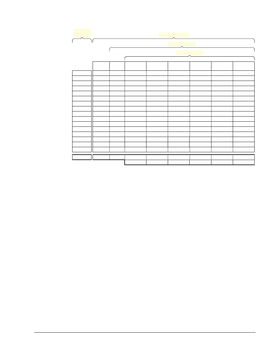
shows how the registers are banked in the ARM Architecture except
ARMv6-M and ARMv7-M.
Overview of the ARM Architecture
ARM DUI 0379C
Copyright © 2007-2008, 2011 ARM. All rights reserved.
3-9
ID061811
Non-Confidential
Figure 3-1 Organization of general-purpose registers and Program Status Registers
In ARMv6-M and ARMv-7M based processors, SP is an alias for the two banked stack pointer
registers:
•
Main stack pointer register, which is only available in privileged software execution.
•
Process stack pointer register.
3.7.1
See also
Concepts
•
General-purpose registers on page 3-10
•
•
Application Program Status Register on page 3-16
•
Saved Program Status Registers (SPSRs) on page 3-19
•
Current Program Status Register on page 3-18
•
Processor modes, and privileged and unprivileged software execution on page 3-5
Reference
•
ARM Architecture Reference Manual,
http://infocenter.arm.com/help/topic/com.arm.doc.subset.arch.reference/index.html.
User
mode
System
mode
Supervisor
mode
Monitor
mode
‡
Abort
mode
Undefined
mode
IRQ
mode
FIQ
mode
R0_usr
R1_usr
R2_usr
R3_usr
R4_usr
R5_usr
R6_usr
R7_usr
R8_usr
R9_usr
R10_usr
R11_usr
R12_usr
SP_usr
LR_usr
PC
CPSR
APSR
SPSR_svc
SPSR_mon
‡
SPSR_abt
SPSR_und
SPSR_irq
SPSR_fiq
LR_svc
LR_mon
‡
LR_abt
LR_und
LR_irq
LR_fiq
SP_svc
SP_mon
‡
SP_abt
SP_und
SP_irq
SP_fiq
R8_fiq
R9_fiq
R10_fiq
R11_fiq
R12_fiq
R12
SP
LR
PC
R11
R10
R9
R8
R7
R6
R5
R4
R3
R2
R1
R0
Exception modes
Privileged modes
System level views
Application
level view
‡ Monitor mode and the associated banked registers are implemented only as part of the Security Extensions

Overview of the ARM Architecture
ARM DUI 0379C
Copyright © 2007-2008, 2011 ARM. All rights reserved.
3-10
ID061811
Non-Confidential
3.8
General-purpose registers
With the exception of ARMv6-M and ARMv7-M based processors, there are 30 (or 32 if
Security Extensions are implemented) general-purpose 32-bit registers, that include the banked
SP and LR registers. Fifteen general-purpose registers are visible at any one time, depending on
the current processor mode. These are R0-R12, SP, LR. The PC (R15) is not considered a
general-purpose register.
SP (or R13) is the stack pointer. The C and C++ compilers always use SP as the stack pointer.
Use of SP as a general purpose register is discouraged. In Thumb, SP is strictly defined as the
stack pointer. The instruction pages in the Assembler Reference describes when SP and PC can
be used.
In User mode, LR (or R14) is used as a link register to store the return address when a subroutine
call is made. It can also be used as a general-purpose register if the return address is stored on
the stack.
In the exception handling modes, LR holds the return address for the exception, or a subroutine
return address if subroutine calls are executed within an exception. LR can be used as a
general-purpose register if the return address is stored on the stack.
Note
When using the
--use_frame_pointer
option with
armcc
, do not use
R11
as a general-purpose
register.
3.8.1
See also
Concepts
•
•
Register accesses on page 3-11
•
Predeclared core register names on page 3-12
.
Reference
Assembler Reference:
•
•
.
Reference
Compiler Reference:
•

Overview of the ARM Architecture
ARM DUI 0379C
Copyright © 2007-2008, 2011 ARM. All rights reserved.
3-11
ID061811
Non-Confidential
3.9
Register accesses
Most 16-bit Thumb instructions can only access R0 to R7. Only a small number of these
instructions can access R8-R12, SP, LR, and PC. Registers R0 to R7 are called Lo registers.
Registers R8-R12, SP, LR, and PC are called Hi registers.
In 32-bit Thumb, all instructions can access R0 to R12, and LR. However, apart from a few
designated stack manipulation instructions, most Thumb instructions cannot use SP. Except for
a few specific instructions where PC is useful, most Thumb instructions cannot use PC.
In ARM state, all instructions can access R0 to R12, SP, and LR, and most instructions can also
access PC (R15). However, the use of the SP in an ARM instruction, in any way that is not
possible in the corresponding Thumb instruction, is deprecated. Explicit use of the PC in an
ARM instruction is not usually useful, and except for specific instances that are useful, such use
is deprecated. Implicit use of the PC, for example in branch instructions or load (literal)
instructions, is never deprecated.
The
MRS
instructions can move the contents of a status register to a general-purpose register,
where they can be manipulated by normal data processing operations. The
MSR
instruction can
be used to move the contents of a general-purpose register to a status register.
3.9.1
See also
Concepts
•
General-purpose registers on page 3-10
•
•
Application Program Status Register on page 3-16
•
Current Program Status Register on page 3-18
•
Saved Program Status Registers (SPSRs) on page 3-19
•
Predeclared core register names on page 3-12
•
Read-Modify-Write procedure on page 5-28
Reference
Assembler Reference:
•
•
.

Overview of the ARM Architecture
ARM DUI 0379C
Copyright © 2007-2008, 2011 ARM. All rights reserved.
3-12
ID061811
Non-Confidential
3.10
Predeclared core register names
shows the predeclared core registers:
With the exception of
a1
-
a4
and
v1
-
v8
, you can write the registers either in all upper case or all
lower case.
3.10.1
See also
Concepts
•
General-purpose registers on page 3-10
Table 3-2 Predeclared core registers
Register names
Meaning
r0-r15
and
R0-R15
General purpose registers.
a1-a4
Argument, result or scratch registers. These are synonyms for
R0
to
R3
v1-v8
Variable registers. These are synonyms for
R4
to R
11
.
sb
and
SB
Static base register. This is a synonym for R
9
.
ip
and
IP
Intra procedure call scratch register. This is a synonym for
R12
.
sp
and
SP
Stack pointer. This is a synonym for
R13
.
lr
and
LR
Link register. This is a synonym for R
14
.
pc
and
PC
Program counter. This is a synonym for
R15
.

Overview of the ARM Architecture
ARM DUI 0379C
Copyright © 2007-2008, 2011 ARM. All rights reserved.
3-13
ID061811
Non-Confidential
3.11
Predeclared extension register names
The following extension register names are predeclared:
You can write the registers either in upper case or lower case.
3.11.1
See also
Concepts
•
Extension register bank mapping on page 9-6
.
Table 3-3 Predeclared extension registers
Register names
Meaning
d0-d31
and
D0-D31
VFP double-precision registers.
s0-s31
and
S0-S31
VFP single-precision registers.

Overview of the ARM Architecture
ARM DUI 0379C
Copyright © 2007-2008, 2011 ARM. All rights reserved.
3-14
ID061811
Non-Confidential
3.12
Predeclared coprocessor names
The following coprocessor names and coprocessor register names are predeclared:
All register and coprocessor names are case-sensitive.
3.12.1
See also
Reference
Assembler Reference:
•
•
MCR, MCR2, MCRR, and MCRR2 on page 3-126
•
MRC, MRC2, MRRC and MRRC2 on page 3-127
.
Table 3-4 Predeclared coprocessor registers
Register name
Meaning
p0-p15
Coprocessors 0-15.
c0-c15
Coprocessor registers 0-15.

Overview of the ARM Architecture
ARM DUI 0379C
Copyright © 2007-2008, 2011 ARM. All rights reserved.
3-15
ID061811
Non-Confidential
3.13
Program Counter
The Program Counter (PC) is accessed as PC (or R15). It is incremented by the size of the
instruction executed (which is always four bytes in ARM state). Branch instructions load the
destination address into PC. You can also load the PC directly using data operation instructions.
For example, to branch to the address in a general purpose register, use:
MOV PC,R0
During execution, PC does not contain the address of the currently executing instruction. The
address of the currently executing instruction is typically PC–8 for ARM, or PC–4 for Thumb.
Note
Writing to the PC directly is not the recommended method for jumping to an address or
returning from a function. Use the
BX
instruction instead.
3.13.1
See also
Concepts
•
Register-relative and PC-relative expressions on page 8-7
Reference
•

Overview of the ARM Architecture
ARM DUI 0379C
Copyright © 2007-2008, 2011 ARM. All rights reserved.
3-16
ID061811
Non-Confidential
3.14
Application Program Status Register
The Application Program Status Register (APSR) holds copies of the Arithmetic Logic Unit
(ALU) status flags. They are also known as the condition code flags. They are used to determine
whether conditional instructions are executed or not.
On ARMv5TE, ARMv6 and later architectures, the APSR also holds the Q (saturation) flag.
On ARMv6 and later, the APSR also holds the GE (Greater than or Equal) flags. The GE flags
can be set by the parallel add and subtract instructions. The GE flags are used by the
SEL
instruction to perform byte-based selection from two registers.
These flags are accessible in all modes, using
MSR
and
MRS
instructions.
3.14.1
See also
Concepts
•
Updates to the ALU status flags on page 6-5
•
Conditional instructions on page 6-2
.
Reference
Assembler Reference:
•
•
•
•

Overview of the ARM Architecture
ARM DUI 0379C
Copyright © 2007-2008, 2011 ARM. All rights reserved.
3-17
ID061811
Non-Confidential
3.15
The Q flag
ARMv5TE, ARMv6 and later have a Q flag that is set to 1 when saturation has occurred in
saturating arithmetic instructions, or when overflow has occurred in certain multiply
instructions.
The Q flag is a sticky flag. Although the saturating and certain multiply instructions can set the
flag, they cannot clear it. You can execute a series of such instructions, and then test the flag to
find out whether saturation or overflow occurred at any point in the series, without having to
check the flag after each instruction.
To clear the Q flag, use an
MSR
instruction to read-modify-write the APSR:
MRS r5, APSR
BIC r5, r5, #(1<<27)
MSR APSR_nzcvq, r5
The state of the Q flag cannot be tested directly by the condition codes. To read the state of the
Q flag, use an
MRS
instruction.
MRS r6, APSR
TST r6, #(1<<27); Z is clear if Q flag was set
3.15.1
See also
Concepts
•
Read-Modify-Write procedure on page 5-28
Reference
Assembler Reference:
•
•
•
QADD, QSUB, QDADD, and QDSUB on page 3-97
•
SMULxy and SMLAxy on page 3-80
•

Overview of the ARM Architecture
ARM DUI 0379C
Copyright © 2007-2008, 2011 ARM. All rights reserved.
3-18
ID061811
Non-Confidential
3.16
Current Program Status Register
The Current Program Status Register (CPSR) holds:
•
the APSR flags
•
the current processor mode
•
interrupt disable flags
•
current processor state (ARM, Thumb, ThumbEE, or Jazelle
®
)
•
endianness state (on ARMv4T and later)
•
execution state bits for the IT block (on ARMv6T2 and later).
The execution state bits control conditional execution in the IT block.
Only the APSR flags are accessible in all modes. The endianness bit (E) of the CPSR is
accessible only in privileged software execution. It can be read by
MRS
and written by
MSR
, but
SETEND
is the preferred instruction to write to the E bit.
The execution state bits for the IT block (IT[1:0]), Jazelle bit (J), and Thumb bit (T) can be
accessed by
MRS
only in Debug state.
3.16.1
See also
Concepts
•
Updates to the ALU status flags on page 6-5
•
Saved Program Status Registers (SPSRs) on page 3-19
.
Reference
Assembler Reference:
•
•
•
•
.

Overview of the ARM Architecture
ARM DUI 0379C
Copyright © 2007-2008, 2011 ARM. All rights reserved.
3-19
ID061811
Non-Confidential
3.17
Saved Program Status Registers (SPSRs)
The SPSR is used to store the current value of the CPSR when an exception is taken so that it
can be restored after handling the exception. Each exception handling mode can access its own
SPSR. User mode and System mode do not have an SPSR because they are not exception
handling modes.
The execution state bits, endianness state and current processor state can be accessed from the
SPSR in any exception mode, using the
MSR
and
MRS
instruction.
3.17.1
See also
Concepts
•

Overview of the ARM Architecture
ARM DUI 0379C
Copyright © 2007-2008, 2011 ARM. All rights reserved.
3-20
ID061811
Non-Confidential
3.18
Instruction set overview
All ARM instructions are 32 bits long. Instructions are stored word-aligned, so the least
significant two bits of instruction addresses are always zero in ARM state.
Thumb and ThumbEE instructions are either 16 or 32 bits long. Instructions are stored
half-word aligned. Some instructions use the least significant bit of the address to determine
whether the code being branched to is Thumb code or ARM code.
Before the introduction of Thumb-2, the Thumb instruction set was limited to a restricted subset
of the functionality of the ARM instruction set. Almost all Thumb instructions were 16-bit. The
Thumb-2 instruction set functionality is almost identical to that of the ARM instruction set.
describes some of the functional groupings of the available instructions.
3.18.1
See also
Concepts
•
Load and store multiple register instructions on page 5-20
.
Table 3-5 Instruction groups
Instruction
Group
Description
Branch and
control
These instructions are used to:
•
branch to subroutines
•
branch backwards to form loops
•
branch forward in conditional structures
•
make following instructions conditional without branching
•
change the processor between ARM state and Thumb state.
Data
processing
These instructions operate on the general-purpose registers. They can
perform operations such as addition, subtraction, or bitwise logic on the
contents of two registers and place the result in a third register. They can also
operate on the value in a single register, or on a value in a register and an
immediate value supplied within the instruction.
Long multiply instructions give a 64-bit result in two registers.
Register load
and store
These instructions load or store the value of a single register from or to
memory. They can load or store a 32-bit word, a 16-bit halfword, or an 8-bit
unsigned byte. Byte and halfword loads can either be sign extended or zero
extended to fill the 32-bit register.
A few instructions are also defined that can load or store 64-bit doubleword
values into two 32-bit registers.
Multiple
register load
and store
These instructions load or store any subset of the general-purpose registers
from or to memory.
Status
register
access
These instructions move the contents of a status register to or from a
general-purpose register.
Coprocessor
These instructions support a general way to extend the ARM architecture.
They also enable the control of the CP15 System Control coprocessor
registers.

Overview of the ARM Architecture
ARM DUI 0379C
Copyright © 2007-2008, 2011 ARM. All rights reserved.
3-21
ID061811
Non-Confidential
Reference
Assembler Reference:
•

Overview of the ARM Architecture
ARM DUI 0379C
Copyright © 2007-2008, 2011 ARM. All rights reserved.
3-22
ID061811
Non-Confidential
3.19
Media processing instructions
Media processing instructions are available in the media extension for ARMv6 and later. The
media processing instructions are:
Parallel add and subtract instructions:
•
Parallel add and subtract on page 3-102
Extend instructions:
•
SXT, SXTA, UXT, and UXTA on page 3-111
.
Multiply instructions:
•
•
SMLALD and SMLSLD on page 3-91
•
SMMUL, SMMLA, and SMMLS on page 3-87
•
SMUAD{X} and SMUSD{X} on page 3-85
Packing, unpacking, saturation, and reversal instructions:
•
•
REV, REV16, REVSH, and RBIT on page 3-69
•
•
•
SSAT16 and USAT16 on page 3-106
.
Absolute sum and bit field instructions:
•
•
•
USAD8 and USADA8 on page 3-104
Note
BFC
and
BFI
are available on ARMv6T2 and above.

Overview of the ARM Architecture
ARM DUI 0379C
Copyright © 2007-2008, 2011 ARM. All rights reserved.
3-23
ID061811
Non-Confidential
3.20
Access to the inline barrel shifter
The ARM arithmetic logic unit has a 32-bit barrel shifter that is capable of shift and rotate
operations. The second operand to many ARM and Thumb data-processing and single register
data-transfer instructions can be shifted, before the data-processing or data-transfer is executed,
as part of the instruction. This supports, but is not limited to:
•
scaled addressing
•
multiplication by an immediate value
•
constructing immediate values.
32-bit Thumb instructions give almost the same access to the barrel shifter as ARM instructions.
The 16-bit Thumb instructions only allow access to the barrel shifter using separate instructions.
3.20.1
See also
Concepts
•
Load immediates into registers on page 5-5
•
Load immediate values using MOV and MVN on page 5-6
.

ARM DUI 0379C
Copyright © 2007-2008, 2011 ARM. All rights reserved.
4-1
ID061811
Non-Confidential
Chapter 4
Structure of Assembly Language Modules
Assembly language is the language that the assembler (
armasm
) parses and assembles to produce
object code. The following topics describe the structure of the assembly source files:
•
Syntax of source lines in assembly language on page 4-2
•
•
ELF sections and the AREA directive on page 4-5
•
An example ARM assembly language module on page 4-6
.

Structure of Assembly Language Modules
ARM DUI 0379C
Copyright © 2007-2008, 2011 ARM. All rights reserved.
4-2
ID061811
Non-Confidential
4.1
Syntax of source lines in assembly language
The general form of source lines in assembly language is:
{symbol} {instruction|directive|pseudo-instruction} {;comment}
All three sections of the source line are optional.
symbol
is usually a label. In instructions and pseudo-instructions it is always a label. In some
directives it is a symbol for a variable or a constant. The description of the directive makes this
clear in each case.
symbol
must begin in the first column. It cannot contain any white space character such as a
space or a tab unless it is enclosed by bars (|).
Labels are symbolic representations of addresses. You can use labels to mark specific addresses
that you want to refer to from other parts of the code. Local labels are a subclass of labels that
begin with a number in the range 0-99. Unlike other labels, a local label can be defined many
times. This make them useful when generating labels with a macro.
Directives provide important information to the assembler that either affects the assembly
process or affects the final output image.
Instructions and pseudo-instructions make up the code a processor uses to perform tasks.
Note
Instructions, pseudo-instructions, and directives must be preceded by white space, such as a
space or a tab, irrespective of whether there is a preceding label or not.
Some directives do not allow the use of a label.
A comment is the final part of a source line. The first semicolon on a line marks the beginning
of a comment except where the semicolon appears inside a string literal. The end of the line is
the end of the comment. A comment alone is a valid line. The assembler ignores all comments.
You can use blank lines to make your code more readable.
Instruction mnemonics, pseudo-instructions, directives, and symbolic register names (except
a1
-
a4
and
v1
-
v8
) can be written in all uppercase or all lowercase, but not mixed. Labels and
comments can be in uppercase or lowercase, or mixed.
Example 4-1
AREA ARMex, CODE, READONLY
; Name this block of code ARMex
ENTRY ; Mark first instruction to execute
start
MOV r0, #10 ; Set up parameters
MOV r1, #3
ADD r0, r0, r1 ; r0 = r0 + r1
stop
MOV r0, #0x18 ; angel_SWIreason_ReportException
LDR r1, =0x20026 ; ADP_Stopped_ApplicationExit
SVC
#0x123456 ; ARM semihosting (formerly SWI)
END ; Mark end of file

Structure of Assembly Language Modules
ARM DUI 0379C
Copyright © 2007-2008, 2011 ARM. All rights reserved.
4-3
ID061811
Non-Confidential
To make source files easier to read, a long line of source can be split onto several lines by placing
a backslash character (
\
) at the end of the line. The backslash must not be followed by any other
characters (including spaces and tabs). The assembler treats the backslash followed by
end-of-line sequence as white space. You can also use blank lines to make your code more
readable.
Note
Do not use the backslash followed by end-of-line sequence within quoted strings.
The limit on the length of lines, including any extensions using backslashes, is 4095 characters.
4.1.1
See also
Concepts
•
•
•
Symbol naming rules on page 8-3
•
•
•

Structure of Assembly Language Modules
ARM DUI 0379C
Copyright © 2007-2008, 2011 ARM. All rights reserved.
4-4
ID061811
Non-Confidential
4.2
Literals
In assembly source files, literals can be expressed as:
•
decimal numbers, for example
123
•
hexadecimal numbers, for example
0x7B
•
numbers in any base from
2
to
9
, for example
5_204
is a number in base
5
•
floating point numbers, for example
123.4
•
boolean values
{TRUE}
or
{FALSE}
•
single character values enclosed by single quotes, for example
‘w’
•
strings enclosed in double quotes, for example
"This is a string"
.
Note
In most cases, a string containing a single character is accepted as a single character value. For
example
ADD r0,r1,#”a”
ia accepted, but
ADD r0,r1,#”ab”
is faulted.
You can also use variables and names to represent the literals.
4.2.1
See also
Concepts
•

Structure of Assembly Language Modules
ARM DUI 0379C
Copyright © 2007-2008, 2011 ARM. All rights reserved.
4-5
ID061811
Non-Confidential
4.3
ELF sections and the AREA directive
ELF sections are independent, named, indivisible sequences of code or data. A single code
section is the minimum required to produce an application.
The output of an assembly or compilation can include:
•
one or more code sections. These are usually read-only sections.
•
one or more data sections. These are usually read-write sections. They might be zero
initialized (ZI).
The linker places each section in a program image according to section placement rules.
Sections that are adjacent in source files are not necessarily adjacent in the application image
In a source file, the
AREA
directive marks the start of a section. This directive names the section
and sets its attributes. The attributes are placed after the name, separated by commas.
You can choose any name for your sections. However, names starting with any non-alphabetic
character must be enclosed in bars, or an
AREA name missing
error is generated. For example,
|1_DataArea|
.
defines a single read-only section called
ARMex
that contains code.
Example 4-2
AREA ARMex, CODE, READONLY
; Name this block of code ARMex
4.3.1
See also
Concepts
•
An example ARM assembly language module on page 4-6
.
Using the Linker:
•
.
Reference
Assembler Reference:
•
.

Structure of Assembly Language Modules
ARM DUI 0379C
Copyright © 2007-2008, 2011 ARM. All rights reserved.
4-6
ID061811
Non-Confidential
4.4
An example ARM assembly language module
illustrates some of the core constituents of an assembly language module. The
example is written in ARM assembly language.
The constituent parts of this example are:
•
ELF sections (defined by the
AREA
directive)
•
application entry (defined by the
ENTRY
directive)
•
application execution
•
application termination
•
program end (defined by the
END
directive).
defines a single section called
ARMex
that contains code and is marked as being
READONLY
.
Example 4-3 Constituents of an assembly language module
AREA ARMex, CODE, READONLY
; Name this block of code ARMex
ENTRY ; Mark first instruction to execute
start
MOV r0, #10 ; Set up parameters
MOV r1, #3
ADD r0, r0, r1 ; r0 = r0 + r1
stop
MOV r0, #0x18 ; angel_SWIreason_ReportException
LDR r1, =0x20026 ; ADP_Stopped_ApplicationExit
SVC
#0x123456 ; ARM semihosting (formerly SWI)
END ; Mark end of file
4.4.1
Application entry
The
ENTRY
directive declares an entry point to the program. It marks the first instruction to be
executed. In applications using the C library, an entry point is also contained within the C library
initialization code. Initialization code and exception handlers also contain entry points.
4.4.2
Application execution
The application code in
start
, where it loads the
decimal values 10 and 3 into registers
R0
and
R1
. These registers are added together and the result
placed in
R0
.
4.4.3
Application termination
After executing the main code, the application terminates by returning control to the debugger.
This is done using the ARM semihosting SVC (
0x123456
by default), with the following
parameters:
•
R0 equal to
angel_SWIreason_ReportException
(
0x18
)
•
R1 equal to
ADP_Stopped_ApplicationExit
(
0x20026
).

Structure of Assembly Language Modules
ARM DUI 0379C
Copyright © 2007-2008, 2011 ARM. All rights reserved.
4-7
ID061811
Non-Confidential
4.4.4
Program end
The
END
directive instructs the assembler to stop processing this source file. Every assembly
language source module must finish with an
END
directive on a line by itself. Any lines following
the
END
directive are ignored by the assembler.
4.4.5
See also
Concepts
•
ELF sections and the AREA directive on page 4-5
.
Reference
Assembler Reference:
•
•

ARM DUI 0379C
Copyright © 2007-2008, 2011 ARM. All rights reserved.
5-1
ID061811
Non-Confidential
Chapter 5
Writing ARM Assembly Language
The following topics describe the use of a few basic assembler instructions and the use of
macros:
•
Unified Assembler Language on page 5-3
•
•
Load immediates into registers on page 5-5
•
Load immediate values using MOV and MVN on page 5-6
•
Load 32-bit values to a register using MOV32 on page 5-9
•
Load immediate 32-bit values to a register using LDR Rd, =const on page 5-10
•
Load addresses into registers on page 5-13
•
Load addresses to a register using ADR on page 5-14
•
Load addresses to a register using ADRL on page 5-16
•
Load addresses to a register using LDR Rd, =label on page 5-17
•
Other ways to Load and store registers on page 5-19
•
Load and store multiple register instructions on page 5-20
•
Load and store multiple instructions available in ARM and Thumb on page 5-21
•
Stack implementation using LDM and STM on page 5-22
•
Stack operations for nested subroutines on page 5-24
•
Block copy with LDM and STM on page 5-25
•
•
Read-Modify-Write procedure on page 5-28
•
•
•

Writing ARM Assembly Language
ARM DUI 0379C
Copyright © 2007-2008, 2011 ARM. All rights reserved.
5-2
ID061811
Non-Confidential
•
Unsigned integer division macro example on page 5-32
•
Instruction and directive relocations on page 5-34
•
•
•
Exception tables and Unwind tables on page 5-38
•
Assembly language changes after RVCTv2.1 on page 5-39
.

Writing ARM Assembly Language
ARM DUI 0379C
Copyright © 2007-2008, 2011 ARM. All rights reserved.
5-3
ID061811
Non-Confidential
5.1
Unified Assembler Language
Unified Assembler Language (UAL) is a common syntax for ARM and Thumb instructions. It
supersedes earlier versions of both the ARM and Thumb assembler languages.
Code written using UAL can be assembled for ARM or Thumb for any ARM processor. The
assembler faults the use of unavailable instructions.
RVCT v2.1 and earlier can only assemble the pre-UAL syntax. Later versions of RVCT and
ARM Compiler toolchain can assemble code written in pre-UAL and UAL syntax.
By default, the assembler expects source code to be written in UAL. The assembler accepts
UAL syntax if any of the directives
CODE32
,
ARM
,
THUMB
, or
THUMBX
is used or if you assemble with
any of the --
32
, --
arm
, --
thumb
, or --
thumbx
command line options. The assembler also accepts
source code written in pre-UAL ARM assembly language when you assemble with
CODE32
or
ARM
.
The assembler accepts source code written in pre-UAL Thumb assembly language when
you assemble using the
--16
command line option, or the
CODE16
directive in the source code.
Note
The pre-UAL Thumb assembly language does not support Thumb-2 instructions.
5.1.1
See also
Concepts
•
Assembly language changes after RVCTv2.1 on page 5-39
.

Writing ARM Assembly Language
ARM DUI 0379C
Copyright © 2007-2008, 2011 ARM. All rights reserved.
5-4
ID061811
Non-Confidential
5.2
Subroutines calls
A subroutine is a block of code that performs a task based on some arguments and optionally
returns a result. By convention, registers R0 to R3 are used to pass arguments to subroutines,
and R0 is used to pass a result back to the callers. A subroutine that needs more than 4 inputs
uses the stack for the additional inputs.
To call subroutines, use a branch and link instruction. The syntax is:
BL destination
where
destination
is usually the label on the first instruction of the subroutine.
destination
can also be a PC-relative expression.
The
BL
instruction:
•
places the return address in the link register
•
sets the PC to the address of the subroutine.
After the subroutine code is executed you can use a
BX LR
instruction to return.
Note
Calls between separately assembled or compiled modules must comply with the restrictions and
conventions defined by the Procedure Call Standard for the ARM Architecture.
shows a subroutine,
doadd
, that adds the values of two arguments and returns a
result in
R0
.
Example 5-1 Add two arguments
AREA subrout, CODE, READONLY ; Name this block of code
ENTRY ; Mark first instruction to execute
start MOV r0, #10 ; Set up parameters
MOV r1, #3
BL doadd ; Call subroutine
stop MOV r0, #0x18 ; angel_SWIreason_ReportException
LDR r1, =0x20026 ; ADP_Stopped_ApplicationExit
SVC
#0x123456 ; ARM semihosting (formerly SWI)
doadd ADD r0, r0, r1 ; Subroutine code
BX lr ; Return from subroutine
END ; Mark end of file
5.2.1
See also
Concepts
•
Stack operations for nested subroutines on page 5-24
Reference
•
B, BL, BX, BLX, and BXJ on page 3-116
•
Procedure Call Standard for the ARM Architecture specification,
http://infocenter/help/topic/com.arm.doc.ihi0042-

Writing ARM Assembly Language
ARM DUI 0379C
Copyright © 2007-2008, 2011 ARM. All rights reserved.
5-5
ID061811
Non-Confidential
5.3
Load immediates into registers
ARM and Thumb instructions can only be 32-bits wide. You can use the
MOV
and
MVN
instructions
to load a register with an immediate value supported by the instruction set. Certain 32-bit values
cannot be represented as an immediate operand to a single 32-bit instruction. These values can
be loaded from memory in a single instruction.
In ARMv6T2 and later, you can load any 32-bit immediate value into a register with two
instructions, a
MOV
followed by a
MOVT
. You can use a pseudo-instruction,
MOV32
, to construct the
instruction sequence for you.
You can also use the
LDR
pseudo-instruction to load immediate values into a register.
You can include many commonly-used immediate values directly as operands within data
processing instructions, without a separate load operation. The range of immediate values that
you can include as operands in 16-bit Thumb instructions is much smaller.
5.3.1
See also
Concepts
•
Load immediate values using MOV and MVN on page 5-6
•
Load 32-bit values to a register using MOV32 on page 5-9
•
Load immediate 32-bit values to a register using LDR Rd, =const on page 5-10
•
Load values to VFP registers on page 9-9
.

Writing ARM Assembly Language
ARM DUI 0379C
Copyright © 2007-2008, 2011 ARM. All rights reserved.
5-6
ID061811
Non-Confidential
5.4
Load immediate values using MOV and MVN
In ARM state:
•
MOV
can load any 8-bit immediate value, giving a range of
0x0
-
0xFF
(0-255).
It can also rotate these values by any even number.
These values are also available as immediate operands in many data processing
operations, without being loaded in a separate instruction.
•
MVN
can load the bitwise complements of these values. The numerical values are
-(n+1)
,
where
n
is the value available in
MOV
.
•
In ARMv6T2 and later,
MOV
can load any 16-bit number, giving a range of
0x0-0xFFFF
(0-65535).
shows the range of 8-bit values that can be loaded in a single ARM
MOV
or
MVN
instruction (for data processing operations). The value to load must be a multiple of the value
shown in the Step column.
shows the range of 16-bit values that can be loaded in a single
MOV
ARM instruction
in ARMv6T2 and later.
Note
These notes give extra information on
a
The
MVN
values are only available directly as operands in
MVN
instructions.
b
These values are available in ARM state only. All the other values in this table are
also available in 32-bit Thumb.
c
These values are only available in ARMv6T2 and later. They are not available
directly as operands in other instructions.
Table 5-1 ARM state immediate values (8-bit)
Binary
Decimal
Step
Hexadecimal
MVN value
a
Notes
000000000000000000000000abcdefgh
0-255
1
0-0xFF
–1 to –256
-
0000000000000000000000abcdefgh00
0-1020
4
0-0x3FC
–4 to –1024
-
00000000000000000000abcdefgh0000
0-4080
16
0-0xFF0
–16 to –4096
-
000000000000000000abcdefgh000000
0-16320
64
0-0x3FC0
–64 to –16384
-
...
...
...
...
...
-
abcdefgh000000000000000000000000
0-255 x 2
24
2
24
0-0xFF000000
1-256 x –2
24
-
cdefgh000000000000000000000000ab
(bit pattern)
-
-
(bit pattern)
See b in Note
efgh000000000000000000000000abcd
(bit pattern)
-
-
(bit pattern)
See b in Note
gh000000000000000000000000abcdef
(bit pattern)
-
-
(bit pattern)
See b in Note
Table 5-2 ARM state immediate values in MOV instructions
Binary
Decimal
Step
Hexadecimal
MVN value
Notes
0000000000000000abcdefghijklmnop
0-65535
1
0-0xFFFF
-
See c in Note

Writing ARM Assembly Language
ARM DUI 0379C
Copyright © 2007-2008, 2011 ARM. All rights reserved.
5-7
ID061811
Non-Confidential
In Thumb state in ARMv6T2 and later:
•
the 32-bit
MOV
instruction can load:
—
any 8-bit immediate value, giving a range of
0x0
-
0xFF
(0-255)
—
any 8-bit immediate value, shifted left by any number
—
any 8-bit pattern duplicated in all four bytes of a register
—
any 8-bit pattern duplicated in bytes 0 and 2, with bytes 1 and 3 set to 0
—
any 8-bit pattern duplicated in bytes 1 and 3, with bytes 0 and 2 set to 0.
These values are also available as immediate operands in many data processing
operations, without being loaded in a separate instruction.
•
the 32-bit
MVN
instruction can load the bitwise complements of these values. The numerical
values are
-(n+1)
, where
n
is the value available in
MOV
.
•
the 32-bit
MOV
instruction can load any 16-bit number, giving a range of
0x0-0xFFFF
(0-65535). These values are not available as immediate operands in data processing
operations.
In architectures with Thumb, the 16-bit Thumb
MOV
instruction can load any immediate value in
the range 0-255.
shows the range of values that can be loaded in a single 32-bit Thumb
MOV
or
MVN
instruction (for data processing operations). The value to load must be a multiple of the value
shown in the Step column.
shows the range of 16-bit values that can be loaded by the
MOV
32-bit Thumb
instruction.
Table 5-3 32-bit Thumb immediate values
Binary
Decimal
Step
Hexadecimal
MVN value
a
Notes
000000000000000000000000abcdefgh
0-255
1
0-0xFF
–1 to –256
-
00000000000000000000000abcdefgh0
0-510
2
0-0x1FE
–2 to –512
-
0000000000000000000000abcdefgh00
0-1020
4
0-0x3FC
–4 to –1024
-
...
...
...
...
...
-
0abcdefgh00000000000000000000000
0-255 x 2
23
2
23
0-0x7F800000
1-256 x –2
23
-
abcdefgh000000000000000000000000
0-255 x 2
24
2
24
0-0xFF000000
1-256 x –2
24
-
abcdefghabcdefghabcdefghabcdefgh
(bit pattern)
-
0xXYXYXYXY
0xXYXYXYXY
-
00000000abcdefgh00000000abcdefgh
(bit pattern)
-
0x00XY00XY
0xFFXYFFXY
-
abcdefgh00000000abcdefgh00000000
(bit pattern)
-
0xXY00XY00
0xXYFFXYFF
-
00000000000000000000abcdefghijkl
0-4095 1
0-0xFFF
-
See b in Note
Table 5-4 32-bit Thumb immediate values in MOV instructions
Binary
Decimal
Step
Hexadecimal
MVN value
Notes
0000000000000000abcdefghijklmnop
0-65535
1
0-0xFFFF
-
See c in Note

Writing ARM Assembly Language
ARM DUI 0379C
Copyright © 2007-2008, 2011 ARM. All rights reserved.
5-8
ID061811
Non-Confidential
Note
These notes give extra information on
.
a
The
MVN
values are only available directly as operands in
MVN
instructions.
b
These values are available directly as operands in
ADD
,
SUB
, and
MOV
instructions,
but not in
MVN
or any other data processing instructions.
c
These values are only available in
MOV
instructions.
In both ARM and Thumb, you do not have to decide whether to use
MOV
or
MVN
. The assembler
uses whichever is appropriate. This is useful if the value is an assembly-time variable.
If you write an instruction with an immediate value that is not available, the assembler reports
the error:
Immediate n out of range for this operation.
5.4.1
See also
Concepts
•

Writing ARM Assembly Language
ARM DUI 0379C
Copyright © 2007-2008, 2011 ARM. All rights reserved.
5-9
ID061811
Non-Confidential
5.5
Load 32-bit values to a register using MOV32
In ARMv6T2 and later, both ARM and Thumb instruction sets include:
•
a
MOV
instruction that can load any value in the range
0x00000000
to
0x0000FFFF
into a
register
•
a
MOVT
instruction that can load any value in the range
0x0000
to
0xFFFF
into the most
significant half of a register, without altering the contents of the least significant half.
You can use these two instructions to construct any 32-bit immediate value in a register.
Alternatively, you can use the
MOV32
pseudo-instruction. The assembler generates the
MOV
,
MOVT
instruction pair for you.
You can also use the
MOV32
instruction to load addresses into registers by using a label or any
PC-relative expression in place of an immediate value. The assembler puts a relocation directive
into the object file for the linker to resolve the address at link-time.
5.5.1
See also
Concepts
•
Register-relative and PC-relative expressions on page 8-7
Reference
Assembler Reference:
•

Writing ARM Assembly Language
ARM DUI 0379C
Copyright © 2007-2008, 2011 ARM. All rights reserved.
5-10
ID061811
Non-Confidential
5.6
Load immediate 32-bit values to a register using LDR Rd, =const
The
LDR Rd,=const
pseudo-instruction can construct any 32-bit numeric value in a single
instruction. You can use this pseudo-instruction to generate constants that are out of range of the
MOV
and
MVN
instructions.
The
LDR
pseudo-instruction generates the most efficient single instruction for the specified
immediate value:
•
If the immediate value can be constructed with a single
MOV
or
MVN
instruction, the
assembler generates the appropriate instruction.
•
If the immediate value cannot be constructed with a single
MOV
or
MVN
instruction, the
assembler:
—
places the value in a literal pool (a portion of memory embedded in the code to hold
constant values)
—
generates an
LDR
instruction with a PC-relative address that reads the constant from
the literal pool.
For example:
LDR rn, [pc, #offset to literal pool]
; load register n with one word
; from the address [pc + offset]
You must ensure that there is a literal pool within range of the
LDR
instruction generated
by the assembler.
5.6.1
See also
Concepts
•
.
Reference
Assembler Reference:
•

Writing ARM Assembly Language
ARM DUI 0379C
Copyright © 2007-2008, 2011 ARM. All rights reserved.
5-11
ID061811
Non-Confidential
5.7
Literal pools
The assembler uses literal pools to hold certain constant values that are to be loaded into
registers. The assembler places a literal pool at the end of each section. The end of a section is
defined either by the
END
directive at the end of the assembly or by the
AREA
directive at the start
of the following section. The
END
directive at the end of an included file does not signal the end
of a section.
In large sections the default literal pool can be out of range of one or more
LDR
instructions. The
offset from the PC to the constant must be:
•
less than 4KB in ARM or 32-bit Thumb code, but can be in either direction
•
forward and less than 1KB in 16-bit Thumb
LDR
instruction.
When an
LDR Rd,=const
pseudo-instruction requires the immediate value to be placed in a literal
pool, the assembler:
•
Checks if the value is available and addressable in any previous literal pools. If so, it
addresses the existing constant.
•
Attempts to place the value in the next literal pool if it is not already available.
If the next literal pool is out of range, the assembler generates an error message. In this case you
must use the
LTORG
directive to place an additional literal pool in the code. Place the
LTORG
directive after the failed
LDR
pseudo-instruction, and within ±4KB (ARM, 32-bit Thumb-2) or
in the range 0 to +1KB (16-bit Thumb).
You must place literal pools where the processor does not attempt to execute them as
instructions. Place them after unconditional branch instructions, or after the return instruction at
the end of a subroutine.
shows how this works.
The instructions listed as comments are the ARM instructions generated by the assembler.
Example 5-2 Placing literal pools
AREA Loadcon, CODE, READONLY
ENTRY ; Mark first instruction to execute
start
BL func1 ; Branch to first subroutine
BL func2 ; Branch to second subroutine
stop
MOV r0, #0x18 ; angel_SWIreason_ReportException
LDR r1, =0x20026 ; ADP_Stopped_ApplicationExit
SVC
#0x123456 ; ARM semihosting (formerly SWI)
func1
LDR r0, =42 ; => MOV R0, #42
LDR r1, =0x55555555 ; => LDR R1, [PC, #offset to
; Literal Pool 1]
LDR r2, =0xFFFFFFFF ; => MVN R2, #0
BX lr
LTORG ; Literal Pool 1 contains
; literal Ox55555555
func2
LDR r3, =0x55555555 ; => LDR R3, [PC, #offset to
; Literal Pool 1]
; LDR r4, =0x66666666 ; If this is uncommented it
; fails, because Literal Pool 2
; is out of reach
BX lr
LargeTable

Writing ARM Assembly Language
ARM DUI 0379C
Copyright © 2007-2008, 2011 ARM. All rights reserved.
5-12
ID061811
Non-Confidential
SPACE 4200 ; Starting at the current location,
; clears a 4200 byte area of memory
; to zero
END ; Literal Pool 2 is empty
5.7.1
See also
Concepts
•
Load immediate 32-bit values to a register using LDR Rd, =const on page 5-10
•

Writing ARM Assembly Language
ARM DUI 0379C
Copyright © 2007-2008, 2011 ARM. All rights reserved.
5-13
ID061811
Non-Confidential
5.8
Load addresses into registers
It is often necessary to load an address into a register. You might have to load the address of a
variable, a string literal, or the start location of a jump table.
Addresses are normally expressed as offsets from a label, or from the current PC or other
register.
You can load an address into a register either:
•
using the instruction
ADR
•
using the instruction
ADRL
•
using the instruction
MOV32
•
from a literal pool using the pseudo-instruction
LDR
Rd
,
=Label
.
5.8.1
See also
Concepts
•
Load addresses to a register using ADR on page 5-14
•
Load addresses to a register using ADRL on page 5-16
•
Load 32-bit values to a register using MOV32 on page 5-9
•
Load addresses to a register using LDR Rd, =label on page 5-17

Writing ARM Assembly Language
ARM DUI 0379C
Copyright © 2007-2008, 2011 ARM. All rights reserved.
5-14
ID061811
Non-Confidential
5.9
Load addresses to a register using ADR
The
ADR
instruction enables you to generate an address, within a certain range, without
performing a data load.
ADR
accepts a PC-relative expression, that is, a label with an optional
offset where the address of the label is relative to the current PC.
Note
The label used with
ADR
must be within the same code section. The assembler faults references
to labels that are out of range in the same section.
The available range of addresses for the
ADR
instruction depends on the instruction set:
ARM
±255 bytes to a byte or halfword-aligned address.
±1020 bytes to a word-aligned address.
32-bit Thumb
±4095 bytes to a byte, halfword, or word-aligned address.
16-bit Thumb
0 to 1020 bytes.
label
must be word-aligned. You can use the
ALIGN
directive to ensure this.
5.9.1
Example of a jump table implementation with ADR
shows ARM code that implements a jump table. Here, the
ADR
instruction loads the
address of the jump table.
Example 5-3 Implementing a jump table (ARM)
AREA Jump, CODE, READONLY ; Name this block of code
ARM ; Following code is ARM code
num EQU 2 ; Number of entries in jump table
ENTRY ; Mark first instruction to execute
start ; First instruction to call
MOV r0, #0 ; Set up the three parameters
MOV r1, #3
MOV r2, #2
BL arithfunc ; Call the function
stop
MOV r0, #0x18 ; angel_SWIreason_ReportException
LDR r1, =0x20026 ; ADP_Stopped_ApplicationExit
SVC
#0x123456 ; ARM semihosting (formerly SWI)
arithfunc ; Label the function
CMP r0, #num ; Treat function code as unsigned integer
BXHS lr ; If code is >= num then simply return
ADR r3, JumpTable ; Load address of jump table
LDR pc, [r3,r0,LSL#2] ; Jump to the appropriate routine
JumpTable
DCD DoAdd
DCD DoSub
DoAdd
ADD r0, r1, r2 ; Operation 0
BX lr ; Return
DoSub
SUB r0, r1, r2 ; Operation 1
BX lr ; Return
END ; Mark the end of this file

Writing ARM Assembly Language
ARM DUI 0379C
Copyright © 2007-2008, 2011 ARM. All rights reserved.
5-15
ID061811
Non-Confidential
In
, the function
arithfunc
takes three arguments and returns a result
in
R0
. The first argument determines the operation to be carried out on the second and third
arguments:
argument1=0
Result = argument2 + argument3.
argument1=1
Result = argument2 – argument3.
The jump table is implemented with the following instructions and assembler directives:
EQU
Is an assembler directive. It is used to give a value to a symbol. In
it assigns the value 2 to
num
. When
num
is used elsewhere in the code,
the value 2 is substituted. Using
EQU
in this way is similar to using
#define
to
define a constant in C.
DCD
Declares one or more words of store. In
DCD
stores
the address of a routine that handles a particular clause of the jump table.
LDR
The
LDR PC,[R3,R0,LSL#2]
instruction loads the address of the required clause of
the jump table into the PC. It:
•
multiplies the clause number in
R0
by 4 to give a word offset
•
adds the result to the address of the jump table
•
loads the contents of the combined address into the PC.
5.9.2
See also
Concepts
•
Load addresses to a register using LDR Rd, =label on page 5-17
•
Load addresses to a register using ADR on page 5-14
.
Reference
Assembler Reference:
•

Writing ARM Assembly Language
ARM DUI 0379C
Copyright © 2007-2008, 2011 ARM. All rights reserved.
5-16
ID061811
Non-Confidential
5.10
Load addresses to a register using ADRL
The
ADRL
pseudo-instruction enables you to generate an address, within a certain range, without
performing a data load.
ADRL
accepts a PC-relative expression, that is, a label with an optional
offset where the address of the label is relative to the current PC.
Note
The label used with
ADRL
must be within the same code section. The assembler faults references
to labels that are out of range in the same section.
ADRL
is not available in Thumb state on processors before ARMv6T2.
The assembler converts an
ADRL rn,label
pseudo-instruction by generating:
•
two data processing instructions that load the address, if it is in range
•
an error message if the address cannot be constructed in two instructions.
The available range depends on the instruction set in use:
ARM
±64KB to a byte or halfword-aligned address.
±256KB to a word-aligned address.
32-bit Thumb
±1MB to a byte, halfword, or word-aligned address.
16-bit Thumb
ADRL
is not available.
5.10.1
See also
Concepts
•
Load addresses to a register using LDR Rd, =label on page 5-17
•
Load addresses to a register using ADR on page 5-14
.

Writing ARM Assembly Language
ARM DUI 0379C
Copyright © 2007-2008, 2011 ARM. All rights reserved.
5-17
ID061811
Non-Confidential
5.11
Load addresses to a register using LDR Rd, =label
The
LDR Rd,=
pseudo-instruction can load any 32-bit numeric value into a register. It also accepts
PC-relative expressions such as labels, and labels with offsets.
The assembler converts an
LDR R0, =label
pseudo-instruction by:
•
placing the address of
label
in a literal pool (a portion of memory embedded in the code
to hold constant values)
•
generating a PC-relative
LDR
instruction that reads the address from the literal pool, for
example:
LDR rn [pc, #offset to literal pool]
; load register n with one word
; from the address [pc + offset]
You must ensure that there is a literal pool within range (see
for more information).
Unlike the
ADR
and
ADRL
pseudo-instructions, you can use
LDR
with labels that are outside the
current section. The assembler places a relocation directive in the object code when the source
file is assembled. The relocation directive instructs the linker to resolve the address at link time.
The address remains valid wherever the linker places the section containing the
LDR
and the
literal pool.
shows how this works.
The instructions listed in the comments are the ARM instructions generated by the assembler.
Example 5-4 Loading using LDR Rd, =label
AREA LDRlabel, CODE,READONLY
ENTRY ; Mark first instruction to execute
start
BL func1 ; Branch to first subroutine
BL func2 ; Branch to second subroutine
stop
MOV r0, #0x18 ; angel_SWIreason_ReportException
LDR r1, =0x20026 ; ADP_Stopped_ApplicationExit
SVC
#0x123456 ; ARM semihosting (formerly SWI)
func1
LDR r0, =start ; => LDR R0,[PC, #offset into
; Literal Pool 1]
LDR r1, =Darea + 12 ; => LDR R1,[PC, #offset into
; Literal Pool 1]
LDR r2, =Darea + 6000 ; => LDR R2, [PC, #offset into
; Literal Pool 1]
BX
lr
; Return
LTORG ; Literal Pool 1
func2
LDR r3, =Darea + 6000 ; => LDR r3, [PC, #offset into
; Literal Pool 1]
; (sharing with previous literal)
; LDR r4, =Darea + 6004 ; If uncommented produces an error
; as Literal Pool 2 is out of range
BX lr ; Return
Darea SPACE 8000 ; Starting at the current location,
; clears a 8000 byte area of memory

Writing ARM Assembly Language
ARM DUI 0379C
Copyright © 2007-2008, 2011 ARM. All rights reserved.
5-18
ID061811
Non-Confidential
; to zero
END ; Literal Pool 2 is out of range of
; the LDR instructions above
5.11.1
An LDR Rd, =label example: string copying
shows an ARM code routine that overwrites one string with another string. It uses
the
LDR
pseudo-instruction to load the addresses of the two strings from a data section. The
following are particularly significant:
DCB
The
DCB
directive defines one or more bytes of store. In addition to integer values,
DCB
accepts quoted strings. Each character of the string is placed in a consecutive
byte.
LDR, STR
The
LDR
and
STR
instructions use post-indexed addressing to update their address
registers. For example, the instruction:
LDRB r2,[r1],#1
loads
R2
with the contents of the address pointed to by
R1
and then increments
R1
by 1.
Example 5-5 String copy
AREA StrCopy, CODE, READONLY
ENTRY ; Mark first instruction to execute
start
LDR r1, =srcstr ; Pointer to first string
LDR r0, =dststr ; Pointer to second string
BL strcopy ; Call subroutine to do copy
stop
MOV r0, #0x18 ; angel_SWIreason_ReportException
LDR r1, =0x20026 ; ADP_Stopped_ApplicationExit
SVC
#0x123456 ; ARM semihosting (formerly SWI)
strcopy
LDRB r2, [r1],#1 ; Load byte and update address
STRB r2, [r0],#1 ; Store byte and update address
CMP r2, #0 ; Check for zero terminator
BNE strcopy ; Keep going if not
MOV pc,lr ; Return
AREA Strings, DATA, READWRITE
srcstr DCB "First string - source",0
dststr DCB "Second string - destination",0
END
5.11.2
See also
Concepts
•
Load immediate 32-bit values to a register using LDR Rd, =const on page 5-10
Reference
Assembler Reference:
•
LDR pseudo-instruction on page 3-158
•

Writing ARM Assembly Language
ARM DUI 0379C
Copyright © 2007-2008, 2011 ARM. All rights reserved.
5-19
ID061811
Non-Confidential
5.12
Other ways to Load and store registers
You can load any 32-bit value from memory into a register with an
LDR
data load instruction. To
store registers into memory you can use the
STR
data store instruction.
You can use the
MOV
instruction to move any 32-bit data from one register to another.
5.12.1
See also
Concepts
•
Load and store multiple register instructions on page 5-20
•
Load and store multiple instructions available in ARM and Thumb on page 5-21
Reference
Assembler Reference:
•
Memory access instructions on page 3-9
•

Writing ARM Assembly Language
ARM DUI 0379C
Copyright © 2007-2008, 2011 ARM. All rights reserved.
5-20
ID061811
Non-Confidential
5.13
Load and store multiple register instructions
The ARM and Thumb instruction sets include instructions that load and store multiple registers
to and from memory.
Multiple register transfer instructions provide an efficient way of moving the contents of several
registers to and from memory. They are most often used for block copy and for stack operations
at subroutine entry and exit. The advantages of using a multiple register transfer instruction
instead of a series of single data transfer instructions include:
•
Smaller code size.
•
A single instruction fetch overhead, rather than many instruction fetches.
•
On uncached ARM processors, the first word of data transferred by a load or store
multiple is always a nonsequential memory cycle, but all subsequent words transferred
can be sequential memory cycles. Sequential memory cycles are faster in most systems.
Note
The lowest numbered register is transferred to or from the lowest memory address accessed, and
the highest numbered register to or from the highest address accessed. The order of the registers
in the register list in the instructions makes no difference.
You can use the
--diag_warning 1206
assembler command line option to check that registers in
register lists are specified in increasing order.
5.13.1
See also
Concepts
•
Load and store multiple instructions available in ARM and Thumb on page 5-21
•
Stack implementation using LDM and STM on page 5-22
•
Stack operations for nested subroutines on page 5-24
•
Block copy with LDM and STM on page 5-25
.

Writing ARM Assembly Language
ARM DUI 0379C
Copyright © 2007-2008, 2011 ARM. All rights reserved.
5-21
ID061811
Non-Confidential
5.14
Load and store multiple instructions available in ARM and Thumb
The following instructions are available in both ARM and Thumb instruction sets:
LDM
Load Multiple registers.
STM
Store Multiple registers.
PUSH
Store multiple registers onto the stack and update the stack pointer.
POP
Load multiple registers off the stack, and update the stack pointer.
In
LDM
and
STM
instructions:
•
The list of registers loaded or stored can include:
—
in ARM instructions, any or all of R0-R12, SP, LR, and PC
—
in 32-bit Thumb instructions, any or all of R0-R12, and optionally LR or PC (
LDM
only) with some restrictions
—
in 16-bit Thumb instructions, any or all of R0-R7.
•
The address can be:
—
incremented after each transfer
—
incremented before each transfer (ARM instructions only)
—
decremented after each transfer (ARM instructions only)
—
decremented before each transfer (not in 16-bit Thumb).
•
The base register can be either:
—
updated to point to the next block of data in memory
—
left as it was before the instruction.
When the base register is updated to point to the next block in memory, this is called writeback,
that is, the adjusted address is written back to the base register.
In
PUSH
and
POP
instructions:
•
The stack pointer (SP) is the base register, and is always updated.
•
The address is incremented after each transfer in
POP
instructions, and decremented before
each transfer in
PUSH
instructions.
•
The list of registers loaded or stored can include:
—
in ARM instructions, any or all of R0-R12, SP, LR, and PC
—
in 32-bit Thumb instructions, any or all of R0-R12, and optionally LR or PC (
POP
only) with some restrictions
—
in 16-bit Thumb instructions, any or all of R0-R7, and optionally LR (
PUSH
only) or
PC (
POP
only).
Note
Use of SP in the list of registers in any of these ARM instructions is deprecated.
ARM
STM
and
PUSH
instructions that use PC in the list of registers, and ARM
LDM
and
POP
instructions that use both PC and LR in the list of registers are deprecated.
5.14.1
See also
Concepts
•
Load and store multiple register instructions on page 5-20
.

Writing ARM Assembly Language
ARM DUI 0379C
Copyright © 2007-2008, 2011 ARM. All rights reserved.
5-22
ID061811
Non-Confidential
5.15
Stack implementation using LDM and STM
The load and store multiple instructions can update the base register. For stack operations, the
base register is usually the stack pointer, SP. This means that you can use these instructions to
implement push and pop operations for any number of registers in a single instruction.
The load and store multiple instructions can be used with several types of stack:
Descending or ascending
The stack grows downwards, starting with a high address and progressing to a
lower one (a descending stack), or upwards, starting from a low address and
progressing to a higher address (an ascending stack).
Full or empty
The stack pointer can either point to the last item in the stack (a full stack), or the
next free space on the stack (an empty stack).
To make it easier for the programmer, stack-oriented suffixes can be used instead of the
increment or decrement, and before or after suffixes.
shows the stack-oriented
suffixes and their equivalent addressing mode suffixes for load and store instructions.
shows the load and store multiple instructions with the stack-oriented suffixes for the
various stack types.
For example:
STMFD sp!, {r0-r5} ; Push onto a Full Descending Stack
LDMFD sp!, {r0-r5} ; Pop from a Full Descending Stack
Note
The Procedure Call Standard for the ARM Architecture (AAPCS), and ARM and Thumb C and
C++ compilers always use a full descending stack.
Table 5-5 Stack-oriented suffixes and equivalent addressing mode suffixes
Stack-oriented suffix
For store or push
instructions
For load or pop
instructions
FD (Full Descending stack)
DB (Decrement Before)
IA (Increment After)
FA (Full Ascending stack)
IB (Increment Before)
DA (Decrement After)
ED (Empty Descending stack)
DA (Decrement After)
IB (Increment Before)
EA (Empty Ascending stack)
IA (Increment After)
DB (Decrement Before)
Table 5-6 Suffixes for load and store multiple instructions
Stack type
Store
Load
Full descending
STMFD
(
STMDB
, Decrement Before)
LDMFD
(
LDM
, increment after)
Full ascending
STMFA
(
STMIB
, Increment Before)
LDMFA
(
LDMDA
, Decrement After)
Empty descending
STMED
(
STMDA
, Decrement After)
LDMED
(
LDMIB
, Increment Before)
Empty ascending
STMEA
(
STM
, increment after)
LDMEA
(
LDMDB
, Decrement Before)

Writing ARM Assembly Language
ARM DUI 0379C
Copyright © 2007-2008, 2011 ARM. All rights reserved.
5-23
ID061811
Non-Confidential
The
PUSH
and
POP
instructions assume a full descending stack. They are the preferred synonyms
for
STMDB
and
LDM
with writeback.
5.15.1
See also
Concepts
•
Load and store multiple register instructions on page 5-20
.
Reference
•
Procedure Call Standard for the ARM Architecture,
http://infocenter.arm.com/help/topic/com.arm.doc.ihi0042-/index.html.

Writing ARM Assembly Language
ARM DUI 0379C
Copyright © 2007-2008, 2011 ARM. All rights reserved.
5-24
ID061811
Non-Confidential
5.16
Stack operations for nested subroutines
Stack operations are very useful at subroutine entry and exit. At the start of a subroutine, any
working registers required can be stored on the stack, and at exit they can be popped off again.
In addition, if the link register is pushed onto the stack at entry, additional subroutine calls can
be made safely without causing the return address to be lost. If you do this, you can also return
from a subroutine by popping PC off the stack at exit, instead of popping LR and then moving
that value into PC. For example:
subroutine PUSH {r5-r7,lr} ; Push work registers and lr
; code
BL somewhere_else
; code
POP {r5-r7,pc} ; Pop work registers and pc
Note
Use this with care in mixed ARM and Thumb systems. In ARMv4T systems, you cannot change
state by popping directly into PC. In these cases you must pop the address into a temporary
register and use the
BX
instruction.
In ARMv5T and later, you can change state in this way.
5.16.1
See also
Concepts
•
.

Writing ARM Assembly Language
ARM DUI 0379C
Copyright © 2007-2008, 2011 ARM. All rights reserved.
5-25
ID061811
Non-Confidential
5.17
Block copy with LDM and STM
is an ARM code routine that copies a set of words from a source location to a
destination by copying a single word at a time.
Example 5-6 Block copy without LDM and STM
AREA Word, CODE, READONLY ; name this block of code
num EQU 20 ; set number of words to be copied
ENTRY ; mark the first instruction called
start
LDR r0, =src ; r0 = pointer to source block
LDR r1, =dst ; r1 = pointer to destination block
MOV r2, #num ; r2 = number of words to copy
wordcopy
LDR r3, [r0], #4 ; load a word from the source and
STR r3, [r1], #4 ; store it to the destination
SUBS r2, r2, #1 ; decrement the counter
BNE wordcopy ; ... copy more
stop
MOV r0, #0x18 ; angel_SWIreason_ReportException
LDR r1, =0x20026 ; ADP_Stopped_ApplicationExit
SVC
#0x123456 ; ARM semihosting (formerly SWI)
AREA BlockData, DATA, READWRITE
src DCD 1,2,3,4,5,6,7,8,1,2,3,4,5,6,7,8,1,2,3,4
dst DCD 0,0,0,0,0,0,0,0,0,0,0,0,0,0,0,0,0,0,0,0
END
This module can be made more efficient by using
LDM
and
STM
for as much of the copying as
possible. Eight is a sensible number of words to transfer at a time, given the number of registers
that the ARM has. The number of eight-word multiples in the block to be copied can be found
(if
R2
= number of words to be copied) using:
MOVS r3, r2, LSR #3 ; number of eight word multiples
This value can be used to control the number of iterations through a loop that copies eight words
per iteration. When there are less than eight words left, the number of words left can be found
(assuming that
R2
has not been corrupted) using:
ANDS r2, r2, #7
lists the block copy module rewritten to use
LDM
and
STM
for copying.
Example 5-7 Block copy using LDM and STM
AREA Block, CODE, READONLY ; name this block of code
num EQU 20 ; set number of words to be copied
ENTRY ; mark the first instruction called
start
LDR r0, =src ; r0 = pointer to source block
LDR r1, =dst ; r1 = pointer to destination block
MOV r2, #num ; r2 = number of words to copy
MOV sp, #0x400 ; Set up stack pointer (sp)
blockcopy
MOVS r3,r2, LSR #3 ; Number of eight word multiples
BEQ copywords ; Less than eight words to move?
PUSH {r4-r11} ; Save some working registers
octcopy
LDM r0!, {r4-r11} ; Load 8 words from the source

Writing ARM Assembly Language
ARM DUI 0379C
Copyright © 2007-2008, 2011 ARM. All rights reserved.
5-26
ID061811
Non-Confidential
STM r1!, {r4-r11} ; and put them at the destination
SUBS r3, r3, #1 ; Decrement the counter
BNE octcopy ; ... copy more
POP {r4-r11} ; Don't need these now - restore
; originals
copywords
ANDS r2, r2, #7 ; Number of odd words to copy
BEQ stop ; No words left to copy?
wordcopy
LDR r3, [r0], #4 ; Load a word from the source and
STR r3, [r1], #4 ; store it to the destination
SUBS r2, r2, #1 ; Decrement the counter
BNE wordcopy ; ... copy more
stop
MOV r0, #0x18 ; angel_SWIreason_ReportException
LDR r1, =0x20026 ; ADP_Stopped_ApplicationExit
SVC
#0x123456 ; ARM semihosting (formerly SWI)
AREA BlockData, DATA, READWRITE
src DCD 1,2,3,4,5,6,7,8,1,2,3,4,5,6,7,8,1,2,3,4
dst DCD 0,0,0,0,0,0,0,0,0,0,0,0,0,0,0,0,0,0,0,0
END

Writing ARM Assembly Language
ARM DUI 0379C
Copyright © 2007-2008, 2011 ARM. All rights reserved.
5-27
ID061811
Non-Confidential
5.18
Memory accesses
The following addressing modes are commonly permitted for memory access instructions:
Offset addressing
The offset value is applied to an address obtained from the base register. The
result is used as the address for the memory access. The base register is
unchanged. The assembly language syntax for this mode is:
[Rn, offset]
Pre-indexed addressing
The offset value is applied to an address obtained from the base register. The
result is used as the address for the memory access, and written back into the base
register. The assembly language syntax for this mode is:
[Rn, offset]!
Post-indexed addressing
The address obtained from the base register is used, unchanged, as the address for
the memory access. The offset value is applied to the address, and written back
into the base register. The assembly language syntax for this mode is:
[Rn], offset
In each case,
Rn
is the base register and
offset
can be:
•
an immediate constant
•
an index register,
Rm
•
a shifted index register, such as
Rm
,
LSL
#shift.
5.18.1
See also
Concepts
•
•
Address alignment on page 7-23
.
Reference
Assembler Reference:
•

Writing ARM Assembly Language
ARM DUI 0379C
Copyright © 2007-2008, 2011 ARM. All rights reserved.
5-28
ID061811
Non-Confidential
5.19
Read-Modify-Write procedure
When you want to modify specific bits in a system register, you must ensure that you do not
modify the other bits in the same register. This is because individual bits in a system register
control different system functionality, and modifying them might cause your program to behave
incorrectly. You must use a read-modify-write procedure to ensure that you modify only the bits
you want to change.
To read-modify-write a system register, the instruction sequence must be:
1.
The first instruction copies the value from the target system register to a temporary
general-purpose register.
2.
The next one or more instructions modify the required bits in the general-purpose register.
This can be one or both of:
•
BIC
to clear just the bits that need to be cleared to 0
•
ORR
to set just the bits that need to be set to 1.
3.
The final instruction writes the value from the general-purpose register to the target
system register.
5.19.1
Example
This example shows the read-modify-write procedure to change some bits of a VFP system
register FPSCR without affecting other bits.
VMRS r10,FPSCR ; copy FPSCR into the general-purpose r10
BIC r10,r10,#0x00370000 ; clears STRIDE bits[21:20] and LEN bits[18:16]
ORR r10,r10,#0x00030000 ; sets bits[17:16] (STRIDE =1 and LEN = 4)
VMSR FPSCR,r10 ; copy r10 back into FPSCR
5.19.2
See also
Concepts
•
Register accesses on page 3-11
•
Reference
Assembler Reference:
•
•
•
.

Writing ARM Assembly Language
ARM DUI 0379C
Copyright © 2007-2008, 2011 ARM. All rights reserved.
5-29
ID061811
Non-Confidential
5.20
Optional hash
You do not need to specify a hash before immediate constants in any instruction syntax
(including ARM, Thumb, and VFP instructions). For example, the following are valid
instructions:
BKPT 100
MOVT R1, 256
VCEQ.I8 Q1, Q2, 0
By default, the assembler warns if you do not specify a hash:
WARNING: A1865W: ‘#’ not seen before constant expression.
This can be suppressed with
--diag_suppress=1865
.
If you use the assembler code with another assembler, you are advised to use the # before all
immediates. The disassembler will always show the # for clarity.
5.20.1
See also
Reference
Assembler Reference:
•
Instruction summary on page 3-2
•
VFP instruction summary on page 4-2
.

Writing ARM Assembly Language
ARM DUI 0379C
Copyright © 2007-2008, 2011 ARM. All rights reserved.
5-30
ID061811
Non-Confidential
5.21
Use of macros
A macro definition is a block of code enclosed between
MACRO
and
MEND
directives. It defines a
name that can be used instead of repeating the whole block of code. The main uses for a macro
are:
•
to make it easier to follow the logic of the source code by replacing a block of code with
a single meaningful name
•
to avoid repeating a block of code several times.
5.21.1
See also
Concepts
•
Test-and-branch macro example on page 5-31
•
Unsigned integer division macro example on page 5-32
Reference
Assembler Reference:
•

Writing ARM Assembly Language
ARM DUI 0379C
Copyright © 2007-2008, 2011 ARM. All rights reserved.
5-31
ID061811
Non-Confidential
5.22
Test-and-branch macro example
In ARM code in any processor and in Thumb code in processors before ARMv6T2, a
test-and-branch operation requires two instructions to implement.
You can define a macro definition such as this:
MACRO
$label TestAndBranch $dest, $reg, $cc
$label CMP $reg, #0
B$cc $dest
MEND
The line after the
MACRO
directive is the macro prototype statement. This defines the name
(
TestAndBranch
) you use to invoke the macro. It also defines parameters (
$label
,
$dest
,
$reg
,
and
$cc
). Unspecified parameters are substituted with an empty string. For this macro you must
give values for
$dest
,
$reg
and
$cc
to avoid syntax errors. The assembler substitutes the values
you give into the code.
This macro can be invoked as follows:
test TestAndBranch NonZero, r0, NE
...
...
NonZero
After substitution this becomes:
test CMP r0, #0
BNE NonZero
...
...
NonZero
5.22.1
See also
Concepts
•
•
Unsigned integer division macro example on page 5-32
•
.

Writing ARM Assembly Language
ARM DUI 0379C
Copyright © 2007-2008, 2011 ARM. All rights reserved.
5-32
ID061811
Non-Confidential
5.23
Unsigned integer division macro example
shows a macro that performs an unsigned integer division. It takes four
parameters:
$Bot
The register that holds the divisor.
$Top
The register that holds the dividend before the instructions are executed. After the
instructions are executed, it holds the remainder.
$Div
The register where the quotient of the division is placed. It can be
NULL
(
""
) if only
the remainder is required.
$Temp
A temporary register used during the calculation.
Example 5-8 Unsigned integer division with a macro
MACRO
$Lab DivMod $Div,$Top,$Bot,$Temp
ASSERT $Top <> $Bot ; Produce an error message if the
ASSERT $Top <> $Temp ; registers supplied are
ASSERT $Bot <> $Temp ; not all different
IF "$Div" <> ""
ASSERT $Div <> $Top ; These three only matter if $Div
ASSERT $Div <> $Bot ; is not null ("")
ASSERT $Div <> $Temp ;
ENDIF
$Lab
MOV $Temp, $Bot ; Put divisor in $Temp
CMP $Temp, $Top, LSR #1 ; double it until
90 MOVLS $Temp, $Temp, LSL #1 ; 2 * $Temp > $Top
CMP $Temp, $Top, LSR #1
BLS %b90 ; The b means search backwards
IF "$Div" <> "" ; Omit next instruction if $Div is null
MOV $Div, #0 ; Initialize quotient
ENDIF
91 CMP $Top, $Temp ; Can we subtract $Temp?
SUBCS $Top, $Top,$Temp ; If we can, do so
IF "$Div" <> "" ; Omit next instruction if $Div is null
ADC $Div, $Div, $Div ; Double $Div
ENDIF
MOV $Temp, $Temp, LSR #1 ; Halve $Temp,
CMP $Temp, $Bot ; and loop until
BHS %b91 ; less than divisor
MEND
The macro checks that no two parameters use the same register. It also optimizes the code
produced if only the remainder is required.
To avoid multiple definitions of labels if
DivMod
is used more than once in the assembler source,
the macro uses local labels (90, 91).
shows the code that this macro produces if it is invoked as follows:
ratio DivMod R0,R5,R4,R2

Writing ARM Assembly Language
ARM DUI 0379C
Copyright © 2007-2008, 2011 ARM. All rights reserved.
5-33
ID061811
Non-Confidential
Example 5-9 Output from division macro
ASSERT r5 <> r4 ; Produce an error if the
ASSERT r5 <> r2 ; registers supplied are
ASSERT r4 <> r2 ; not all different
ASSERT r0 <> r5 ; These three only matter if $Div
ASSERT r0 <> r4 ; is not null ("")
ASSERT r0 <> r2 ;
ratio
MOV r2, r4 ; Put divisor in $Temp
CMP r2, r5, LSR #1 ; double it until
90 MOVLS r2, r2, LSL #1 ; 2 * r2 > r5
CMP r2, r5, LSR #1
BLS %b90 ; The b means search backwards
MOV r0, #0 ; Initialize quotient
91 CMP r5, r2 ; Can we subtract r2?
SUBCS r5, r5, r2 ; If we can, do so
ADC r0, r0, r0 ; Double r0
MOV r2, r2, LSR #1 ; Halve r2,
CMP r2, r4 ; and loop until
BHS %b91 ; less than divisor
5.23.1
See also
Concepts
•
•
Test-and-branch macro example on page 5-31
•
.

Writing ARM Assembly Language
ARM DUI 0379C
Copyright © 2007-2008, 2011 ARM. All rights reserved.
5-34
ID061811
Non-Confidential
5.24
Instruction and directive relocations
A relocation is a directive embedded in the object file that enables source code to refer to a label
whose target address is unknown or cannot be calculated at assembly time. The assembler will
emit a relocation in the object file, and the linker resolves this to the address where the target is
placed.
The assembler relocates the data directives
DCB
,
DCW
,
DCWU
,
DCD
, and
DCDU
if their syntax contains
an external symbol, that is a symbol declared using
IMPORT
or
EXTERN
. This causes the bottom 8,
16, or 32 bits of the address to be used at link-time.
The
REQUIRE
directive emits a relocation to signal to the linker that the target label must be
present if the current section is present.
The assembler is permitted to emit a relocation for these instructions:
LDR
(PC-relative)
All ARM and Thumb instructions, except the Thumb doubleword instruction, can
be relocated.
PLD
,
PLDW
, and
PLI
All ARM and Thumb instructions can be relocated.
B
,
BL
, and
BLX
All ARM and Thumb instructions can be relocated.
CBZ
and
CBNZ
All Thumb instructions can be relocated but this is discouraged because of the
limited branch range of these instructions.
LDC
and
LDC2
Only ARM instructions can be relocated.
VLDR
Only ARM instructions can be relocated.
The assembler emits a relocation for the instructions listed above if the label used meets any of
the following requirements, as appropriate for the instruction type:
•
the label is
WEAK
•
the label is not in the same
AREA
•
the label is external to the object (
IMPORT
or
EXTERN
).
For
B
,
BL
, and
BX
instructions, the assembler emits relocation also if:
•
the label is a function
•
the label is function exported using
EXPORT
or
GLOBAL
.
Note
The
RELOC
directive can be used to control the relocation at a finer level, but this needs
knowledge of the ABI.
5.24.1
Example
IMPORT sym
; sym is an external symbol
DCW sym
; Because DCW only outputs 16 bits, only the lower 16 bits
; of the address of sym are inserted at link-time.

Writing ARM Assembly Language
ARM DUI 0379C
Copyright © 2007-2008, 2011 ARM. All rights reserved.
5-35
ID061811
Non-Confidential
5.24.2
See also
Reference
•
ELF for the ARM Architecture,
http://infocenter.arm.com/help/topic/com.arm.doc.ihi0044-/index.html
Assembler Reference:
•
•
•
IMPORT and EXTERN on page 5-71
•
•
•
•
•
•
LDR (PC-relative) on page 3-19
•
ADR (PC-relative) on page 3-24
•
PLD, PLDW, and PLI on page 3-28
•
B, BL, BX, BLX, and BXJ on page 3-116
•
•
LDC, LDC2, STC, and STC2 on page 3-131
•

Writing ARM Assembly Language
ARM DUI 0379C
Copyright © 2007-2008, 2011 ARM. All rights reserved.
5-36
ID061811
Non-Confidential
5.25
Symbol versions
The ARM linker conforms to the Base Platform ABI for the ARM Architecture (BPABI) and
supports the GNU-extended symbol versioning model.
To add a symbol version to an existing symbol, you must define a version symbol at the same
address. A version symbol is of the form:
•
name@ver
if ver is a non default version of name
•
name@@ver
if ver is the default version of name.
The version symbols must be enclosed in vertical bars.
For example, to define a default version:
|my_versioned_symbol@@ver2| ; Default version
my_asm_function PROC
...
BX lr
ENDP
To define a non default version:
|my_versioned_symbol@ver1| ; Non default version
my_old_asm_function PROC
...
BX lr
ENDP
5.25.1
See also
Concepts
Using the Linker:
•
Chapter 7 Accessing and managing symbols with armlink
.
Reference
Base Platform ABI for the ARM Architecture,
http://infocenter.arm.com/help/topic/com.arm.doc.ihi0037-/index.html.

Writing ARM Assembly Language
ARM DUI 0379C
Copyright © 2007-2008, 2011 ARM. All rights reserved.
5-37
ID061811
Non-Confidential
5.26
Frame directives
You must use frame directives to describe the way that your code uses the stack if you want to
be able to do either of the following:
•
debug your application using stack unwinding
•
use either flat or call-graph profiling.
The assembler uses frame directives to insert DWARF debug frame information into the object
file in ELF format that it produces. This information is required by a debugger for stack
unwinding and for profiling.
Be aware of the following:
•
Frame directives do not affect the code produced by the assembler.
•
The assembler does not validate the information in frame directives against the
instructions emitted.
5.26.1
See also
Concepts
•
Exception tables and Unwind tables on page 5-38
.
Reference
•
Procedure Call Standard for the ARM Architecture,
http://infocenter.arm.com/help/topic/com.arm.doc.ihi0042-/index.html.
Assembler Reference:
•
.

Writing ARM Assembly Language
ARM DUI 0379C
Copyright © 2007-2008, 2011 ARM. All rights reserved.
5-38
ID061811
Non-Confidential
5.27
Exception tables and Unwind tables
Exception tables are necessary to handle exceptions thrown by functions in high-level languages
such as C++. Unwind tables contain debug frame information which are also necessary for the
handling of such exceptions. An exception can only propagate through a function with an
unwind table.
Functions written in C++ will have unwind information by default. However, for assembly
language functions (code encased by
PROC
/
ENDP
or
FUNC
/
ENDFUNC
) that are called from C++ code,
you must ensure that there are exception tables and unwind tables to enable the exceptions to
propagate through them.
An exception cannot propagate through a function with a nounwind table. The exception
handling runtime environment terminates the program if it encounters a nounwind table during
exception processing.
The assembler can generate nounwind table entries for all functions and non-functions. The
assembler can generate an unwind table for a function only if the function contains sufficient
FRAME
directives to describe the use of the stack within the function. To be able to create an
unwind table for a function, each
POP
or
PUSH
instruction must be followed by a
FRAME POP
or
FRAME PUSH
directive respectively. Functions must conform to the conditions set out in the
Exception Handling ABI for the ARM Architecture (EHABI), section 9.1 Constraints on Use. If
the assembler cannot generate an unwind table it generates a nounwind table.
5.27.1
See also
Concepts
•
.
Reference
Assembler Reference:
•
•
--no_exceptions_unwind on page 2-18
•
•
•
•
•
•

Writing ARM Assembly Language
ARM DUI 0379C
Copyright © 2007-2008, 2011 ARM. All rights reserved.
5-39
ID061811
Non-Confidential
5.28
Assembly language changes after RVCTv2.1
The assembly language accepted in RVCT v2.1 assembler and earlier is called pre-UAL ARM
and Thumb. The current assembler accepts the UAL and the pre-UAL ARM and Thumb syntax.
The assembler accepts the pre-UAL Thumb syntax only if it is preceded by a
CODE16
directive,
or if the source file is assembled with the
--16
command line option.
For the convenience of programmers who are familiar with the ARM and Thumb assembly
languages accepted in RVCT v2.1 and earlier,
highlights the differences between the
UAL and pre-UAL ARM assembly language syntax.
In addition, some flexibility is permitted that was not permitted in previous assemblers as
shows.
You can write source code for Thumb processors earlier than ARMv6T2 using UAL.
If you are writing Thumb code for a processor earlier than ARMv6T2, you must restrict yourself
to instructions that are available on the processor. The assembler generates error messages if you
attempt to use an instruction that is not available.
If you are writing Thumb code for an ARMv6T2 or later processor, you can minimize your code
size by using 16-bit instructions wherever possible.
Table 5-7 Changes from earlier ARM assembly language
Change
Pre-UAL ARM syntax
Preferred UAL syntax
The default addressing mode for
LDM
and
STM
is
IA
LDMIA, STMIA
LDM
,
STM
You can use the
PUSH
and
POP
mnemonics for full,
descending stack operations in ARM as well as Thumb.
STMFD sp!, {reglist}
LDMFD sp!, {reglist}
PUSH {reglist}
POP {reglist}
You can use the
LSL
,
LSR
,
ASR
,
ROR
, and
RRX
instruction
mnemonics for instructions with rotations and no other
operation, in ARM as well as Thumb.
MOV Rd, Rn, LSL shift
MOV Rd, Rn, LSR shift
MOV Rd, Rn, ASR shift
MOV Rd, Rn, ROR shift
MOV Rd, Rn, RRX
LSL Rd, Rn, shift
LSR Rd, Rn, shift
ASR Rd, Rn, shift
ROR Rd, Rn, shift
RRX Rd, Rn
Use the
label
form for PC-relative addressing. Do not use
the
offset
form in new code.
LDR Rd, [pc, #offset]
LDR Rd, label
Specify both registers for doubleword memory accesses.
You must still obey rules about the register combinations
you can use.
LDRD Rd, addr_mode
LDRD Rd, Rd2, addr_mode
{cond}
, if used, is always the last element of all
instructions.
ADD{cond}S
LDR{cond}SB
ADDS{cond}
LDRSB{cond}
Table 5-8 Relaxation of requirements
Relaxation
Permitted syntax
Preferred syntax
If the destination register is the same as the first operand, you can use
a two register form of the instruction.
ADD r1, r3
ADD r1, r1, r3

Writing ARM Assembly Language
ARM DUI 0379C
Copyright © 2007-2008, 2011 ARM. All rights reserved.
5-40
ID061811
Non-Confidential
shows the main differences between the UAL and the pre-UAL Thumb assembly
language.
5.28.1
See also
Reference
Assembler Reference:
•
ARM, THUMB, THUMBX, CODE16 and CODE32 on page 5-56
.
Table 5-9 Differences between pre-UAL Thumb syntax and UAL syntax
Change
Pre-UAL Thumb syntax
UAL syntax
The default addressing mode for
LDM
and
STM
is
IA
LDMIA
,
STMIA
LDM
,
STM
You must use the
S
postfix on instructions that update the
flags. This change is essential to avoid conflict with 32-bit
Thumb-2 instructions.
ADD r1, r2, r3
SUB r4, r5, #6
MOV r0, #1
LSR r1, r2, #1
ADDS r1, r2, r3
SUBS r4, r5, #6
MOVS r0, #1
LSRS r1, r2, #1
The preferred form for ALU instructions specifies three
registers, even if the destination register is the same as the
first operand. However, the UAL syntax allows the two
register syntax.
ADD r7, r8
SUB r1, #80
ADD r7, r7, r8
SUBS r1, r1, #80
If
Rd
and
Rn
are both Lo registers,
MOV Rd, Rn
is
disassembled as
ADDS Rd, Rn, #0
.
MOV r2, r3
MOV r8, r9
CPY r0, r1
LSL r2, r3, #0
ADDS r2, r3, #0
MOV r8, r9
MOV r0, r1
MOVS r2, r3
NEG Rd, Rm
is disassembled as
RSBS Rd, Rm, #0
.
NEG Rd, Rm
RSBS Rd, Rm, #0

ARM DUI 0379C
Copyright © 2007-2008, 2011 ARM. All rights reserved.
6-1
ID061811
Non-Confidential
Chapter 6
Condition Codes
The following topics describe condition codes and conditional execution of ARM and Thumb
code:
•
Conditional instructions on page 6-2
•
Conditional execution in ARM state on page 6-3
•
Conditional execution in Thumb state on page 6-4
•
Updates to the ALU status flags on page 6-5
•
Condition code suffixes on page 6-6
•
Condition code meanings on page 6-8
•
Benefits of using conditional execution on page 6-10
•
Illustration of the benefits of using conditional instructions on page 6-11
•
Optimization for execution speed on page 6-14
.

Condition Codes
ARM DUI 0379C
Copyright © 2007-2008, 2011 ARM. All rights reserved.
6-2
ID061811
Non-Confidential
6.1
Conditional instructions
You can execute an instruction conditionally based upon the ALU status flags set by another
instruction, either:
•
immediately after the instruction that updated the flags
•
after any number of intervening instructions that have not updated the flags.
The instructions that you can make conditional depends on whether the processor is in ARM
state or Thumb state.
To make an instruction conditional, you must add a condition code suffix to the instruction
mnemonic. The condition code suffix enables the processor to test a condition based on the
flags. If the condition test of a conditional instruction fails, the instruction:
•
does not execute
•
does not write any value to its destination register
•
does not affect any of the flags
•
does not generate any exception.
6.1.1
See also
Concepts
•
Condition code suffixes on page 6-6
•
Conditional execution in ARM state on page 6-3
•

Condition Codes
ARM DUI 0379C
Copyright © 2007-2008, 2011 ARM. All rights reserved.
6-3
ID061811
Non-Confidential
6.2
Conditional execution in ARM state
Almost all ARM instructions can be executed conditionally on the value of the ALU status flags
in the APSR. You can either add a condition code suffix to the instruction or you can
conditionally skip over the instruction using a conditional branch instruction.
Using conditional branches instructions to control the flow of execution can be better when a
series of instructions depend on the same condition.
Example 6-1 Conditional instructions to control execution
; flags set by a previous instruction
LSLEQ r0, r0, #24
ADDEQ r0, r0, #2
;…
Example 6-2 Conditional branch to control execution
; flags set by a previous instruction
BNE over
LSL r0, r0, #24
ADD r0, r0, #2
over
;…
6.2.1
See also
Concepts
•

Condition Codes
ARM DUI 0379C
Copyright © 2007-2008, 2011 ARM. All rights reserved.
6-4
ID061811
Non-Confidential
6.3
Conditional execution in Thumb state
In Thumb state on processors before ARMv6T2, the only mechanism for conditional execution
is a conditional branch. You can conditionally skip over the instruction using a conditional
branch instruction.
In Thumb state on ARMv6T2 or later processors, instructions can also be conditionally
executed by:
•
using
CBZ
and
CBNZ
•
using the
IT
(If-Then) instruction.
The Thumb
CBZ
(Conditional Branch on Zero) and
CBNZ
(Conditional Branch on Non-Zero)
instructions compare the value of a register against zero and branch on the result.
IT
is a 16-bit instruction that enables almost all Thumb instructions to be conditionally executed,
on the value of the ALU flags, using the condition code suffix. Each
IT
instruction provides
conditional execution for up to four following instructions.
Example 6-3 Conditional instructions using IT block
; flags set by a previous instruction
ITT
EQ
LSLEQ r0, r0, #24
ADDEQ r0, r0, #2
;…
6.3.1
See also
Concepts
•
Conditional execution in ARM state on page 6-3
.
Reference
•
•
.

Condition Codes
ARM DUI 0379C
Copyright © 2007-2008, 2011 ARM. All rights reserved.
6-5
ID061811
Non-Confidential
6.4
Updates to the ALU status flags
In ARM state, and in Thumb state on ARMv6T2 or later processors, most data processing
instructions have an option to update ALU status flags in the Application Program Status
Register (APSR) according to the result of the operation. Instructions with the optional S suffix
update the condition flags. Conditional instructions that are not executed have no effect on the
flags.
In Thumb state on processors before ARMv6T2, most data processing instructions update the
ALU status flags automatically according to the result of the operation. There is no option to
leave the flags unchanged and not update them. Other instructions cannot update the flags.
The APSR contains the following ALU status flags:
N
Set to 1 when the result of the operation is negative, cleared to 0 otherwise.
Z
Set to 1 when the result of the operation is zero, cleared to 0 otherwise.
C
Set to 1 when the operation results in a carry, cleared to 0 otherwise.
V
Set to 1 when the operation causes overflow, cleared to 0 otherwise.
A carry occurs:
•
if the result of an addition is greater than or equal to 2
32
•
if the result of a subtraction is positive or zero
•
as the result of an inline barrel shifter operation in a move or logical instruction.
Overflow occurs if the result of an add, subtract, or compare is greater than or equal to 2
31
, or
less than –2
31
.
The instruction also determines the flags that get updated. Some instructions update all flags,
and some instructions only update a subset of the flags. If a flag is not updated, the original value
is preserved. In the Assembler Reference, the description of each instruction details the effect it
has on the flags.
Note
Most instructions update the status flags only if the S suffix is specified. The instructions
CMP
.
CMN
,
TEQ
, and
TST
always update the condition code flags.
6.4.1
See also
Concepts
•

Condition Codes
ARM DUI 0379C
Copyright © 2007-2008, 2011 ARM. All rights reserved.
6-6
ID061811
Non-Confidential
6.5
Condition code suffixes
The instructions that can be conditional have an optional condition code, shown in syntax
descriptions as
{cond}
. This condition is encoded in ARM instructions, and encoded in a
preceding
IT
instruction for Thumb instructions. An instruction with a condition code is only
executed if the condition code flags in the APSR meet the specified condition.
In Thumb state on processors before ARMv6T2, the
{cond}
field is only permitted on certain
branch instructions because there is no
IT
instruction on these processors.
The following table shows the condition codes that you can use and the flags they depend on.
The following is an example of conditional execution.
Example 6-4
ADD r0, r1, r2 ; r0 = r1 + r2, don't update flags
ADDS r0, r1, r2 ; r0 = r1 + r2, and update flags
ADDSCS r0, r1, r2 ; If C flag set then r0 = r1 + r2, and update flags
CMP r0, r1 ; update flags based on r0-r1.
6.5.1
See also
Concepts
•
Updates to the ALU status flags on page 6-5
•
Condition code meanings on page 6-8
Table 6-1 Condition code suffixes
Suffix
Flags
Meaning
EQ
Z
set
Equal
NE
Z
clear
Not equal
CS or HS
C
set
Higher or same (unsigned >= )
CC or LO
C
clear
Lower (unsigned < )
MI
N
set
Negative
PL
N
clear
Positive or zero
VS
V
set
Overflow
VC
V
clear
No overflow
HI
C
set and
Z
clear
Higher (unsigned >)
LS
C
clear or
Z
set
Lower or same (unsigned <=)
GE
N
and
V
the same
Signed >=
LT
N
and
V
differ
Signed <
GT
Z
clear,
N
and
V
the same
Signed >
LE
Z
set,
N
and
V
differ
Signed <=
AL
Any
Always. This suffix is normally omitted.

Condition Codes
ARM DUI 0379C
Copyright © 2007-2008, 2011 ARM. All rights reserved.
6-7
ID061811
Non-Confidential
•
Conditional instructions on page 6-2
.

Condition Codes
ARM DUI 0379C
Copyright © 2007-2008, 2011 ARM. All rights reserved.
6-8
ID061811
Non-Confidential
6.6
Condition code meanings
The precise meanings of the condition code flags differ depending on whether the flags were set
by a floating-point operation or by an ARM data processing instruction. This is because:
•
floating-point values are never unsigned, so the unsigned conditions are not required
•
Not-a-Number (NaN) values have no ordering relationship with numbers or with each
other, so additional conditions are required to account for unordered results.
The only VFP instruction that can be used to update the status flags is
VCMP
. Other VFP
instructions cannot modify the condition code flags.
The
VCMP
instruction does not update the flags in the APSR directly, but updates a separate set
of flags in the FPSCR. To use these flags to control conditional instructions, including
conditional VFP instructions, you must first copy them into the APSR using a
VMRS
instruction:
VMRS APSR_nzcv, FPSCR
The meanings of the condition code mnemonics are shown in
Note
The type of the instruction that last updated the flags in the APSR determines the meaning of
condition codes.
Table 6-2 Condition codes
Mnemonic
Meaning after ARM data processing instruction
Meaning after VFP VCMP instruction
EQ
Equal
Equal
NE
Not equal
Not equal, or unordered
CS
Carry set
Greater than or equal, or unordered
HS
Unsigned higher or same
Greater than or equal, or unordered
CC
Carry clear
Less than
LO
Unsigned lower
Less than
MI
Negative
Less than
PL
Positive or zero
Greater than or equal, or unordered
VS
Overflow
Unordered (at least one NaN operand)
VC
No overflow
Not unordered
HI
Unsigned higher
Greater than, or unordered
LS
Unsigned lower or same
Less than or equal
GE
Signed greater than or equal
Greater than or equal
LT
Signed less than
Less than, or unordered
GT
Signed greater than
Greater than
LE
Signed less than or equal
Less than or equal, or unordered
AL
Always (normally omitted)
Always (normally omitted)

Condition Codes
ARM DUI 0379C
Copyright © 2007-2008, 2011 ARM. All rights reserved.
6-9
ID061811
Non-Confidential
6.6.1
See also
Concepts
•
FPSCR, the floating-point status and control register on page 9-16
•
Condition code suffixes on page 6-6
Reference
Assembler Reference:
•
•
.

Condition Codes
ARM DUI 0379C
Copyright © 2007-2008, 2011 ARM. All rights reserved.
6-10
ID061811
Non-Confidential
6.7
Benefits of using conditional execution
You can use conditional execution of ARM instructions to reduce the number of branch
instructions in your code. This improves code density. The
IT
instruction in Thumb-2 achieves
a similar improvement.
Branch instructions are also expensive in processor cycles. On ARM processors without branch
prediction hardware, it typically takes three processor cycles to refill the processor pipeline each
time a branch is taken.
Some ARM processors, for example StrongARM
®
, have branch prediction hardware. In systems
using these processors, the pipeline only has to be flushed and refilled when there is a
misprediction.
6.7.1
See also
Concepts
•
Illustration of the benefits of using conditional instructions on page 6-11

Condition Codes
ARM DUI 0379C
Copyright © 2007-2008, 2011 ARM. All rights reserved.
6-11
ID061811
Non-Confidential
6.8
Illustration of the benefits of using conditional instructions
This illustrates the difference between using branches and using conditional instructions. It uses
the Euclid algorithm for the Greatest Common Divisor (gcd) to demonstrate how conditional
instructions improve code size and speed.
In C the gcd algorithm can be expressed as:
int gcd(int a, int b)
{
while (a != b)
{
if (a > b)
a = a - b;
else
b = b - a;
}
return a;
}
The following examples show implementations of the gcd algorithm with and without
conditional instructions.
Note
The detailed analysis of execution speed only applies to an ARM7
™
processor. The code density
calculations apply to all ARM processors.
6.8.1
Example of conditional execution using branches in ARM code
This is an ARM code implementation of the gcd algorithm using branches, without using any
other conditional instructions. Conditional execution is achieved by using conditional branches,
rather than individual conditional instructions:
gcd CMP r0, r1
BEQ end
BLT less
SUBS r0, r0, r1 ; could be SUB r0, r0, r1 for ARM
B gcd
less
SUBS r1, r1, r0 ; could be SUB r1, r1, r0 for ARM
B gcd
end
The code is seven instructions long because of the number of branches. Every time a branch is
taken, the processor must refill the pipeline and continue from the new location. The other
instructions and non-executed branches use a single cycle each.
The following table shows the number of cycles this implementation uses on an ARM7
processor when R0 equals 1 and R1 equals 2.
Table 6-3 Conditional branches only
R0: a
R1: b
Instruction
Cycles (ARM7)
1
2
CMP r0, r1
1
1
2
BEQ end
1 (not executed)
1
2
BLT less
3

Condition Codes
ARM DUI 0379C
Copyright © 2007-2008, 2011 ARM. All rights reserved.
6-12
ID061811
Non-Confidential
6.8.2
Example of conditional execution using conditional instructions in ARM code
This is an ARM code implementation of the gcd algorithm using individual conditional
instructions in ARM code. The gcd algorithm only takes four instructions:
gcd
CMP r0, r1
SUBGT r0, r0, r1
SUBLE r1, r1, r0
BNE gcd
In addition to improving code size, in most cases this code executes faster than the version that
uses only branches.
The following table shows the number of cycles this implementation uses on an ARM7
processor when R0 equals 1 and R1 equals 2.
Comparing this with the example that uses only branches:
•
Replacing branches with conditional execution of all instructions saves three cycles.
•
Where R0 equals R1, both implementations execute in the same number of cycles. For all
other cases, the implementation that uses conditional instructions executes in fewer cycles
than the implementation that uses branches only.
1
2
SUB r1, r1, r0
1
1
2
B gcd
3
1
1
CMP r0, r1
1
1
1
BEQ end
3
Total = 13
Table 6-3 Conditional branches only (continued)
R0: a
R1: b
Instruction
Cycles (ARM7)
Table 6-4 All instructions conditional
R0: a
R1: b
Instruction
Cycles (ARM7)
1
2
CMP r0, r1
1
1
2
SUBGT r0,r0,r1
1 (not executed)
1
1
SUBLT r1,r1,r0
1
1
1
BNE gcd
3
1
1
CMP r0,r1
1
1
1
SUBGT r0,r0,r1
1 (not executed)
1
1
SUBLT r1,r1,r0
1 (not executed)
1
1
BNE gcd
1 (not executed)
Total = 10

Condition Codes
ARM DUI 0379C
Copyright © 2007-2008, 2011 ARM. All rights reserved.
6-13
ID061811
Non-Confidential
6.8.3
Example of conditional execution using conditional instructions in Thumb code
In architectures ARMv6T2 and later, you can use the
IT
instruction to write conditional
instructions in Thumb code. The Thumb code implementation of the gcd algorithm using
conditional instructions is very similar to the implementation in ARM code. The
implementation in Thumb code is:
gcd
CMP r0, r1
ITE GT
SUBGT r0, r0, r1
SUBLE r1, r1, r0
BNE gcd
This assembles equally well to ARM or Thumb code. The assembler checks the
IT
instructions,
but omits them on assembly to ARM code.
It requires one more instruction in Thumb code (the
IT
instruction) than in ARM code, but the
overall code size is 10 bytes in Thumb code compared with 16 bytes in ARM code.
6.8.4
Example of conditional execution code using branches in Thumb code
In architectures before ARMv6T2, there is no
IT
instruction and hence Thumb instructions
cannot be executed conditionally except for the
B
branch instruction. The gcd algorithm must be
written with conditional branches and is very similar to the ARM code implementation using
branches, without conditional instructions.
The Thumb code implementation of the gcd algorithm without conditional instructions requires
seven instructions. The overall code size is 14 bytes. This is even less than the ARM
implementation that uses conditional instructions, which uses 16 bytes.
In addition, on a system using 16-bit memory this Thumb implementation runs faster than both
ARM implementations because only one memory access is required for each 16-bit Thumb
instruction, whereas each 32-bit ARM instruction requires two fetches.
6.8.5
See also
Concepts
•
Benefits of using conditional execution on page 6-10
•
Condition code suffixes on page 6-6
•
Optimization for execution speed on page 6-14
.
Reference
ARM Architecture Reference Manual,
http://infocenter.arm.com/help/topic/com.arm.doc.subset.arch.reference/index.html.
Technical Reference Manual for your processor
Assembler Reference:
•

Condition Codes
ARM DUI 0379C
Copyright © 2007-2008, 2011 ARM. All rights reserved.
6-14
ID061811
Non-Confidential
6.9
Optimization for execution speed
To optimize code for execution speed you must have detailed knowledge of the instruction
timings, branch prediction logic, and cache behavior of your target system.
6.9.1
See also
Reference
ARM Architecture Reference Manual,
http://infocenter.arm.com/help/topic/com.arm.doc.subset.arch.reference/index.html.
Technical Reference Manaual for your processor.

ARM DUI 0379C
Copyright © 2007-2008, 2011 ARM. All rights reserved.
7-1
ID061811
Non-Confidential
Chapter 7
Using the Assembler
The following topics describe how to use the Assembler:
•
Assembler command line syntax on page 7-2
•
Assembler commands listed in groups on page 7-3
•
Specify command line options with an environment variable on page 7-6
•
Using stdin to input source code to the assembler on page 7-7
•
Built-in variables and constants on page 7-8
•
Versions of armasm on page 7-12
•
Diagnostic messages on page 7-13
•
Interlocks diagnostics on page 7-14
•
IT block generation on page 7-15
•
Thumb branch target alignment on page 7-16
•
Thumb code size diagnostics on page 7-17
•
ARM and Thumb instruction portability diagnostics on page 7-18
•
Instruction width on page 7-19
•
2 pass assembler diagnostics on page 7-20
•
Using the C preprocessor on page 7-21
•
Address alignment on page 7-23
•
Instruction width selection in Thumb on page 7-24
.

Using the Assembler
ARM DUI 0379C
Copyright © 2007-2008, 2011 ARM. All rights reserved.
7-2
ID061811
Non-Confidential
7.1
Assembler command line syntax
The command for invoking the assembler is:
armasm {options} {inputfile}
where inputfile is an assembly source file and
options
instruct the assembler how to assemble
the inputfile. You can invoke the assembler with any combination options separated by spaces.
Note
The inline and embedded assemblers are part of the C and C++ compilers and do not use any
command line syntax for invocation. However, to pass additional assembler options when the
compiler invokes
armasm
for embedded assembly, you can use the
armcc –A
option.
The assembler command line is case-insensitive, except in filenames and where specified. The
assembler uses the normal command line ordering rules as described in the Using the Compiler.
Therefore, if the command line contains options that conflict with each other, then the last
option found always takes precedence.
7.1.1
See also
Concepts
Using the Compiler:
•
Order of compiler command-line options on page 3-10
•
Compiler command-line options listed by group on page 3-4
.
Reference
•

Using the Assembler
ARM DUI 0379C
Copyright © 2007-2008, 2011 ARM. All rights reserved.
7-3
ID061811
Non-Confidential
7.2
Assembler commands listed in groups
See the following command line options in the Assembler Reference.
Help
•
•
•
Source
•
•
•
•
•
•
•
•
•
•
--predefine "directive" on page 2-20
•
•
•
--regnames=callstd on page 2-21
•
•
•
Output
•
•
--depend=dependfile on page 2-8
•
--depend_format=string on page 2-9
•
•
•
•
•
•
•
•
•
•
•
•
•
•

Using the Assembler
ARM DUI 0379C
Copyright © 2007-2008, 2011 ARM. All rights reserved.
7-4
ID061811
Non-Confidential
•
•
•
•
--untyped_local_labels on page 2-23
Target
•
--apcs=qualifier…qualifier on page 2-5
•
•
•
•
•
•
•
•
--library_type=lib on page 2-15
•
•
--no_unaligned_access on page 2-19
•
--unaligned_access on page 2-23
.
Diagnostics
•
--brief_diagnostics on page 2-6
•
•
--diag_error=tag{, tag} on page 2-9
•
--diag_remark=tag{, tag} on page 2-10
•
--diag_warning=tag{, tag} on page 2-11
•
--diag_suppress=tag{, tag} on page 2-10
•
--diag_style=style on page 2-10
•
--errors=errorfile on page 2-11
•
•
--report-if-not-wysiwyg on page 2-22
•
Preprocessor
•
•
--cpreproc_opts=options on page 2-7
Exception table generation
•
•
--exceptions_unwind on page 2-12
Project template
•
--project=filename on page 2-20
•
--reinitialize_workdir on page 2-21
•

Using the Assembler
ARM DUI 0379C
Copyright © 2007-2008, 2011 ARM. All rights reserved.
7-5
ID061811
Non-Confidential
Command line options in a text file
•
.

Using the Assembler
ARM DUI 0379C
Copyright © 2007-2008, 2011 ARM. All rights reserved.
7-6
ID061811
Non-Confidential
7.3
Specify command line options with an environment variable
You can specify command line options by setting the value of the
ARMCCnn_ASMOPT
environment
variable. The syntax is identical to the command line syntax. The assembler reads the value of
ARMCCnn_ASMOPT
and inserts it at the front of the command string. This means that options
specified in
ARMCCnn_ASMOPT
can be overridden by arguments on the command line.
7.3.1
See also
Concepts
•
Assembler command line syntax on page 7-2
Introducing the ARM Compiler toolchain:
•

Using the Assembler
ARM DUI 0379C
Copyright © 2007-2008, 2011 ARM. All rights reserved.
7-7
ID061811
Non-Confidential
7.4
Using stdin to input source code to the assembler
Instead of creating a file for your source code, you can use
stdin
to pipe output from another
program into
armasm
or to input source code directly on the command line. This is useful if you
want to test a short piece of code without having to create a file for it.
To use
stdin
to pipe output from another program into
armasm
, invoke the program and the
assembler using the pipe character (|). Use the minus character (
-
) as the source filename to
instruct the assembler to take input from
stdin
. You must specify the output filename using the
-o
option. You can specify the command line options you want to use.
To use
stdin
to input source code directly on the command line:
1.
Invoke the assembler with the command line options you want to use. Use the minus
character (
-
) as the source filename to instruct the assembler to take input from
stdin
. You
must specify the output filename using the
-o
option. For example:
armasm --bigend -o output.o -
2.
Enter your input. For example:
AREA ARMex, CODE, READONLY
; Name this block of code ARMex
ENTRY ; Mark first instruction to execute
start
MOV r0, #10 ; Set up parameters
MOV r1, #3
ADD r0, r0, r1 ; r0 = r0 + r1
stop
MOV r0, #0x18 ; angel_SWIreason_ReportException
LDR r1, =0x20026 ; ADP_Stopped_ApplicationExit
SVC #0x123456 ; ARM semihosting (formerly SWI)
END ; Mark end of file
3.
Terminate your input by entering:
•
Ctrl-Z
then
Return
on Microsoft Windows systems
•
Ctrl-D
on Unix-based operating systems.
Note
The source code from
stdin
is stored in an internal cache that can hold up to 8 MB. You can
increase this cache size using the
--maxcache
command line option.
7.4.1
See also
Tasks
Introducing the ARM Compiler toolchain:
•
Using a text file to specify command-line options on page 2-20
.
Reference
•
Assembler command line syntax on page 7-2
•
Assembler commands listed in groups on page 7-3
Introducing the ARM Compiler toolchain:
•
Compilation tools command-line option rules on page 2-17
Assembler Reference:
•
.

Using the Assembler
ARM DUI 0379C
Copyright © 2007-2008, 2011 ARM. All rights reserved.
7-8
ID061811
Non-Confidential
7.5
Built-in variables and constants
lists the built-in variables defined by the assembler.
Built-in variables cannot be set using the
SETA
,
SETL
, or
SETS
directives. They can be used in
expressions or conditions, for example:
IF {ARCHITECTURE} = "4T"
The built-in variable
|ads$version|
must be all in lowercase. The names of the other built-in
variables can be in uppercase, lowercase, or mixed. For example:
Table 7-1 Built-in variables
{ARCHITECTURE}
Holds the name of the selected ARM architecture.
{AREANAME}
Holds the name of the current AREA.
{ARMASM_VERSION}
Holds an integer that increases with each version of
armasm
. The format of the version number is
PVbbbb where:
P
is the major version
V
is the minor version
bbbb
is the build number.
|ads$version|
Has the same value as
{ARMASM_VERSION}
.
{CODESIZE}
Is a synonym for
{CONFIG}
.
{COMMANDLINE}
Holds the contents of the command line.
{CONFIG}
Has the value
32
if the assembler is assembling ARM code, or
16
if it is assembling Thumb code.
{CPU}
Holds the name of the selected CPU. The default is
“ARM7TDMI”
. If an architecture was specified in
the command line
--cpu
option,
{CPU}
holds the value "
Generic ARM
".
{ENDIAN}
Has the value
“big”
if the assembler is in big-endian mode, or
“little”
if it is in little-endian mode.
{FPIC}
Has the boolean value True if
/fpic
is set. The default is False.
{FPU}
Holds the name of the selected FPU. The default is
“SoftVFP”
.
{INPUTFILE}
Holds the name of the current source file.
{INTER}
Has the boolean value True if
/inter
is set. The default is False.
{LINENUM}
Holds an integer indicating the line number in the current source file.
{LINENUMUP}
When used in a macro, holds an integer indicating the line number of the current macro. The value
is same as
{LINENUM}
when used in a non-macro context.
{LINENUMUPPER}
When used in a macro, holds an integer indicating the line number of the top macro. The value is
same as
{LINENUM}
when used in a non-macro context.
{OPT}
Value of the currently-set listing option. The
OPT
directive can be used to save the current listing
option, force a change in it, or restore its original value.
{PC}
or
.
Address of current instruction.
{PCSTOREOFFSET}
Is the offset between the address of the
STR PC,[…]
or
STM Rb,{…, PC}
instruction and the value of
PC stored out. This varies depending on the CPU or architecture specified.
{ROPI}
Has the boolean value True if
/ropi
is set. The default is False.
{RWPI}
Has the boolean value True if
/rwpi
is set. The default is False.
{VAR}
or
@
Current value of the storage area location counter.

Using the Assembler
ARM DUI 0379C
Copyright © 2007-2008, 2011 ARM. All rights reserved.
7-9
ID061811
Non-Confidential
IF {CpU} = "Generic ARM"
Note
All built-in string variables contain case-sensitive values. Relational operations on these built-in
variables will not match with strings that contain an incorrect case. Use the command line
options --
cpu
and --
fpu
to determine valid values for
{CPU}
,
{ARCHITECTURE}
, and
{FPU}
.
lists the built-in Boolean constants defined by the assembler.
lists the target CPU related built-in variables that are predefined by the assembler.
Where the value field is empty, the symbol is a boolean value and the meaning column describes
when its value is {
TRUE
}.
Table 7-2 Built-in Boolean constants
{FALSE}
Logical constant false.
{TRUE}
Logical constant true.
Table 7-3 Predefined macros
Name
Value
Meaning
{TARGET_ARCH_ARM}
num
The number of the ARM base architecture of the target CPU
irrespective of whether the assembler is assembling for ARM or
Thumb. For possible values of
{TARGET_ARCH_ARM}
in relation to the
ARM architecture versions, see
.
{TARGET_ARCH_THUMB}
num
The number of the Thumb base architecture of the target CPU
irrespective of whether the assembler is assembling for ARM or
Thumb. The value is defined as zero if the target does not support
Thumb. For possible values of
{TARGET_ARCH_THUMB}
in relation to the
ARM architecture versions, see
.
{TARGET_ARCH_XX}
–
XX
represents the target architecture and its value depends on the target
CPU. For example, if you specify the assembler option
--cpu=4T
or
--cpu=ARM7TDMI
then
{TARGET_ARCH_4T}
is defined.
shows the possible values for
XX
.
{TARGET_FEATURE_EXTENSION_REGISTER_
COUNT}
num
The number of 64-bit extension registers available in VFP.
{TARGET_FEATURE_CLZ}
–
If target CPU supports the
CLZ
instruction (that is, ARMv5T and later
except ARMv6-M).
{TARGET_FEATURE_DIVIDE}
–
If the target CPU supports the hardware divide instructions
SDIV
and
UDIV
in Thumb (that is, ARMv7-M or ARMv7-R).
{TARGET_FEATURE_DOUBLEWORD}
–
If the target CPU supports the
LDRD
and
STRD
instructions (that is,
ARMv5TE and later except ARMv6-M).
{TARGET_FEATURE_DSPMUL}
–
If the DSP-enhanced multiplier (for example the
SMLAxy
instruction)
is available, for example ARMv5TE.
{TARGET_FEATURE_MULTIPLY}
–
If the target CPU supports the long multiply instructions
SMULL
,
SMLAL
,
UMULL
, and
UMLAL
(that is, all architectures except ARMv6-M).
{TARGET_FEATURE_MULTIPROCESSING}
–
If assembling for a target CPU with ARMv7 Multiprocessing
Extensions.

Using the Assembler
ARM DUI 0379C
Copyright © 2007-2008, 2011 ARM. All rights reserved.
7-10
ID061811
Non-Confidential
shows the possible values for
{TARGET_ARCH_THUMB}
how these values relate to versions of the ARM architecture.
7.5.1
See also
Reference
Assembler Reference:
•
•
{TARGET_FEATURE_UNALIGNED}
–
If the target CPU support for unaligned access (that is, ARMv6 and
later except ARMv6-M).
{TARGET_FPU_SOFTVFP}
If assembling with the option --fpu=softvfp.
{TARGET_FPU_SOFTVFP_VFP}
If assembling for a target CPU with softvfp and a hardware vfp, for
example --fpu=softvfp+vfpv3.
{TARGET_FPU_VFP}
If assembling for a target CPU with a hardware VFP, without using
softvfp, for example --fpu=vfpv3
{TARGET_FPU_VFPV2}
If assembling for a target CPU with VFPv2.
{TARGET_FPU_VFPV3}
If assembling for a target CPU with VFPv3.
{TARGET_PROFILE_M}
If assembling for a Cortex-M profile CPU (that is,
--cpu=6-M
,
--cpu=6S-M
, or
--cpu=7-M
):
{TARGET_PROFILE_R}
If assembling for a Cortex-R profile CPU (that is,
--cpu=7-R
option).
Table 7-3 Predefined macros (continued)
Name
Value
Meaning
Table 7-4 {TARGET_ARCH_ARM} in relation to {TARGET_ARCH_THUMB}
ARM architecture
{TARGET_ARCH_ARM}
{TARGET_ARCH_THUMB}
xx
v4
4
0
4
v4T
4
1
4T
v5T
5
2
5T
v5TE
5
2
5TE
v5TEJ
5
2
5TEJ
v6
6
3
6
v6K
6
3
6K
v6Z
6
3
6Z
v6T2
6
4
6T2
v6-M
0
3
6M
v6S-M
0
3
6SM
v7-R
7
4
7R
v7-M
0
4
7M

Using the Assembler
ARM DUI 0379C
Copyright © 2007-2008, 2011 ARM. All rights reserved.
7-11
ID061811
Non-Confidential
•

Using the Assembler
ARM DUI 0379C
Copyright © 2007-2008, 2011 ARM. All rights reserved.
7-12
ID061811
Non-Confidential
7.6
Versions of armasm
You can use the built-in variable
{ARMASM_VERSION}
to distinguish between versions of
armasm
.
The format of the version number is PVbbbb where:
P
is the major version
V
is the minor version
bbbb
is the build number
The assembler did not have the built-in variable
|ads$version|
before ADS and RVCT. If you
have to build versions of your code using legacy development tools, you can test for the built-in
variable
|ads$version|
. If this variable is not defined, then the assembler is part of a legacy
development toolchain. Use code similar to the following:
IF :DEF: |ads$version|
; code for RealView or ADS
ELSE
; code for SDT (a legacy development toolchain)
ENDIF
7.6.1
See also
Concepts
•
Built-in variables and constants on page 7-8
.

Using the Assembler
ARM DUI 0379C
Copyright © 2007-2008, 2011 ARM. All rights reserved.
7-13
ID061811
Non-Confidential
7.7
Diagnostic messages
In addition to the default error, warning and remark messages, the assembler can provide more
diagnostic messages. By default, these additional diagnostic messages are not displayed.
However, you can enable these additional messages using command line options.
7.7.1
See also
Concepts
•
Interlocks diagnostics on page 7-14
•
IT block generation on page 7-15
•
Thumb branch target alignment on page 7-16
•
Thumb code size diagnostics on page 7-17
•
ARM and Thumb instruction portability diagnostics on page 7-18
•
Instruction width on page 7-19
•
2 pass assembler diagnostics on page 7-20
.
Reference
Assembler Reference:
•
--diag_error=tag{, tag} on page 2-9
.

Using the Assembler
ARM DUI 0379C
Copyright © 2007-2008, 2011 ARM. All rights reserved.
7-14
ID061811
Non-Confidential
7.8
Interlocks diagnostics
You can get warning messages about possible interlocks in your code caused by the pipeline of
the processor chosen by the
--cpu
option. To do this, use the following command line option
when invoking the assembler:
armasm --diag_warning 1563
7.8.1
See also
Concepts
•
Diagnostic messages on page 7-13
•
IT block generation on page 7-15
•
Thumb branch target alignment on page 7-16
•
Instruction width on page 7-19
Reference
Assembler Reference:
•
--diag_error=tag{, tag} on page 2-9
.

Using the Assembler
ARM DUI 0379C
Copyright © 2007-2008, 2011 ARM. All rights reserved.
7-15
ID061811
Non-Confidential
7.9
IT block generation
If you write:
AREA x,CODE
THUMB
MOVNE r0,r1 ; (1)
NOP
IT NE
MOVNE r0,r1 ; (2)
END
the assembler generates an
IT
instruction before the first
MOVNE
instruction.
You can get warning messages about this automatic generation of
IT
blocks when assembling
Thumb code. To do this, use the following command line option when invoking the assembler:
armasm --diag_warning 1763
7.9.1
See also
Concepts
•
Diagnostic messages on page 7-13
Reference
Assembler Reference:
•
--diag_error=tag{, tag} on page 2-9
.

Using the Assembler
ARM DUI 0379C
Copyright © 2007-2008, 2011 ARM. All rights reserved.
7-16
ID061811
Non-Confidential
7.10
Thumb branch target alignment
On some processors, non word-aligned Thumb instructions sometimes take one or more
additional cycles to execute in loops. This means that it can be an advantage to ensure that
branch targets are word-aligned. The assembler can issue warnings when branch targets in
Thumb code are not word-aligned. To do this, use the following command line option when
invoking the assembler:
armasm --diag_warning 1604
7.10.1
See also
Concepts
•
Diagnostic messages on page 7-13
Reference
Assembler Reference:
•
--diag_error=tag{, tag} on page 2-9
.

Using the Assembler
ARM DUI 0379C
Copyright © 2007-2008, 2011 ARM. All rights reserved.
7-17
ID061811
Non-Confidential
7.11
Thumb code size diagnostics
In Thumb code, some instructions, for example a branch or
LDR
(PC-relative), can be encoded
as a 32-bit or 16-bit instruction. The assembler chooses the size of the encoded instruction as
described in Instruction width selection in Thumb.
The assembler can issue warnings when an instruction is assembled to a 32-bit Thumb
instruction where a 16-bit Thumb instruction could have been used. To enable this warning, use
the following command line option when invoking the assembler:
armasm --diag_warning 1813
7.11.1
See also
Concepts
•
Diagnostic messages on page 7-13
•
Instruction width selection in Thumb on page 7-24
•
ARM, Thumb, and ThumbEE instruction sets on page 3-3
Reference
Assembler Reference:
•
--diag_error=tag{, tag} on page 2-9
.

Using the Assembler
ARM DUI 0379C
Copyright © 2007-2008, 2011 ARM. All rights reserved.
7-18
ID061811
Non-Confidential
7.12
ARM and Thumb instruction portability diagnostics
There are a few UAL instructions that can assemble as either ARM code or Thumb code, but
not both. You can identify these instructions in the source code using the following command
line option when invoking the assembler:
armasm --diag_warning 1812
It warns for any instruction that cannot be assembled in the instruction set opposite to the current
one. This is only a hint, and other factors, like relocation availability or target distance might
affect the accuracy of the message.
7.12.1
See also
Concepts
•
Diagnostic messages on page 7-13
•
ARM, Thumb, and ThumbEE instruction sets on page 3-3
Reference
Assembler Reference:
•
--diag_error=tag{, tag} on page 2-9
•
--diag_warning=tag{, tag} on page 2-11
.

Using the Assembler
ARM DUI 0379C
Copyright © 2007-2008, 2011 ARM. All rights reserved.
7-19
ID061811
Non-Confidential
7.13
Instruction width
If you specify the
.W
specifier, the instruction is encoded in 32 bits even if it can be encoded in
16 bits. You can use a diagnostic warning to detect when a branch instruction could have been
encoded in 16 bits, but has been encoded in 32 bits. To do this, use the following command line
option when invoking the assembler:
armasm --diag_warning 1607
Note
This diagnostic does not produce a warning for relocated branch instructions, because the final
address is not known. The linker might even insert a veneer, if the branch is out of range for a
32-bit instruction.
7.13.1
See also
Concepts
•
Diagnostic messages on page 7-13
Reference
Assembler Reference:
•
--diag_error=tag{, tag} on page 2-9
.

Using the Assembler
ARM DUI 0379C
Copyright © 2007-2008, 2011 ARM. All rights reserved.
7-20
ID061811
Non-Confidential
7.14
2 pass assembler diagnostics
The ARM assembler is a two pass assembler and the input code that the assembler reads must
be identical in both passes. If a symbol is defined after the
:DEF:
test for that symbol, then the
code read in pass 1 might be different from the code read in pass 2. The assembler can warn in
this situation.
To do this, use the following command line option when invoking the assembler:
armasm --diag_warning 1907
shows that the symbol foo is defined after the
:DEF: foo
test. Assembling this code
with
--diag_warning 1907
generates the message:
Warning A1907W: Test for this symbol has been seen and may cause failure in the second
pass.
Example 7-1 Symbol test before symbol definition
AREA
x,CODE
[ :DEF: foo
]
foo MOV r3, r4
END
7.14.1
See also
Concepts
•
How the assembler works on page 2-4
•
Diagnostic messages on page 7-13
•
IT block generation on page 7-15
•
Thumb branch target alignment on page 7-16
•
Instruction width on page 7-19
Reference
Assembler Reference:
•
--diag_warning=tag{, tag} on page 2-11
.

Using the Assembler
ARM DUI 0379C
Copyright © 2007-2008, 2011 ARM. All rights reserved.
7-21
ID061811
Non-Confidential
7.15
Using the C preprocessor
You can use C preprocessor commands in your assembly language source file. If you do this,
you must use the
--cpreproc
command line option when invoking the assembler. This causes
armasm
to call
armcc
to preprocess the file before assembling it.
armasm
looks for the
armcc
binary in the same directory as the
armasm
binary. If it does not find
the binary, it expects it to be on the PATH.
armasm
passes certain options to
armcc
if present on the command line. These are shown in
. Some of these options are converted to the
armcc
equivalent before passing to
armcc
.
These are shown in
.
To pass other simple compiler options, such as the preprocessor option
-D
, you must use the
--cpreproc_opts
command line option.
armasm
correctly interprets the preprocessed
#line
commands. It can generate error messages and
debug_line
tables using the information in the
#line
commands.
shows the commands you write to preprocess and assemble a file,
source.s
. The
example also passes the compiler options to define a macro called RELEASE, and to undefine
a macro called ALPHA.
Example 7-2 Preprocessing an assembly language source file
armasm --cpreproc --cpreproc_opts=-D,RELEASE,-U,ALPHA source.s
If you want to use complex preprocessor options, you must manually call
armcc
to preprocess
the file before calling
armasm
shows the commands you write to
manually preprocess and assemble a file,
source.s
. In this example, the preprocessor outputs a
file called
preprocessed.s
, and
armasm
assembles
preprocessed.s
.
Table 7-5 Command-line options
--16
--arm_only
--diag_remark
--fpu
--library_type
--32
--bi
--diag_style
--fpumode
--thumb
--apcs
--cpu
--diag_suppress
--i
--unaligned_access
--no_unaligned_access
--arm
--diag_err
or
--diag_warning
--li
Table 7-6 armcc equivalent command line options
armasm
armcc
--16
--thumb
--32
--arm
--i
--I

Using the Assembler
ARM DUI 0379C
Copyright © 2007-2008, 2011 ARM. All rights reserved.
7-22
ID061811
Non-Confidential
Example 7-3 Preprocessing an assembly language source file manually
armcc -E source.s > preprocessed.s
armasm preprocessed.s
7.15.1
See also
Concepts
Using the Compiler:
•
Compiler command-line options listed by group on page 3-4
.
Reference
Assembler Reference:
•
•

Using the Assembler
ARM DUI 0379C
Copyright © 2007-2008, 2011 ARM. All rights reserved.
7-23
ID061811
Non-Confidential
7.16
Address alignment
For processors based on ARMv5 or earlier, or ARMv6-M, you must ensure that addresses for
4-byte transfers are 4-byte word-aligned, and addresses for 2-byte transfers are 2-byte aligned.
In ARMv6 and later, except ARMv6-M, unaligned accesses are permitted for
LDR
,
LDRH
,
STR
,
STRH
,
LDRSH
,
LDRT
,
STRT
,
LDRSHT
,
LDRHT
,
STRHT
, and
TBH
instructions, where the architecture
supports the instruction.
On some ARM processors, you can enable alignment checking. Non word-aligned 32-bit
transfers cause an alignment exception if alignment checking is enabled.
If all your accesses are aligned, you can use the
--no_unaligned_access
command line option, to
avoid linking in any library functions that might have an unaligned option.
If a processor does not have alignment checking available and enabled:
•
For
STR
, the specified address is rounded down to a multiple of four.
•
For
LDR
:
1.
The specified address is rounded down to a multiple of four.
2.
Four bytes of data are loaded from the resulting address.
3.
The loaded data is rotated right by one, two or three bytes according to bits [1:0] of
the address.
For a little-endian memory system, this causes the addressed byte to occupy the least
significant byte of the register.
For a big-endian memory system, it causes the addressed byte to occupy:
—
bits[31:24] if bit[0] of the address is 0
—
bits[15:8] if bit[0] of the address is 1.
•
For
STM
,
LDM
,
STRD
, and
LDRD
, in ARMv6 and earlier architectures, the specified address is
rounded down to a multiple of 4.
In ARMv7 some instructions will fault regardless of alignment checking.
7.16.1
See also
Reference
Assembler Reference:
•

Using the Assembler
ARM DUI 0379C
Copyright © 2007-2008, 2011 ARM. All rights reserved.
7-24
ID061811
Non-Confidential
7.17
Instruction width selection in Thumb
If you are writing Thumb code for ARMv6T2 or later processors, some instructions can have
either a 16-bit encoding or a 32-bit encoding.
If you do not specify the instruction size, by default:
•
for forward reference
LDR
,
ADR
, and
B
instructions, the assembler always generates a 16-bit
instruction, even if that results in failure for a target that could be reached using a 32-bit
instruction.
•
for external reference
LDR
and
B
instructions, the assembler always generates a 32-bit
instruction.
•
in all other cases, the assembler generates the smallest size encoding that can be output.
If you want to over-ride this behavior, you can use the
.W
or
.N
width specifier to ensure a
particular instruction size. The assembler will fault if it cannot generate an instruction with the
specified width.
The
.W
specifier is ignored when assembling to ARM code, so you can safely use this specifier
in code that might assemble to either ARM or Thumb code. However, the
.N
specifier will be
faulted when assembling to ARM code.
7.17.1
See also
Concepts
•
Thumb code size diagnostics on page 7-17
Reference
Assembler Reference:
•
Instruction width specifiers on page 3-8
.

ARM DUI 0379C
Copyright © 2007-2008, 2011 ARM. All rights reserved.
8-1
ID061811
Non-Confidential
Chapter 8
Symbols, Literals, Expressions, and Operators
The following topics describe how you can use symbols to represent variables, addresses and
constants in code. It also describes how you can combine these with operators to create numeric
or string expressions:
•
Symbol naming rules on page 8-3
•
•
•
Assembly time substitution of variables on page 8-6
•
Register-relative and PC-relative expressions on page 8-7
•
•
Labels for PC-relative addresses on page 8-9
•
Labels for register-relative addresses on page 8-10
•
Labels for absolute addresses on page 8-11
•
•
Syntax of local labels on page 8-13
•
String expressions on page 8-14
•
•
Numeric expressions on page 8-16
•
•
Floating-point literals on page 8-18
•
Logical expressions on page 8-19
•
•
•
•

Symbols, Literals, Expressions, and Operators
ARM DUI 0379C
Copyright © 2007-2008, 2011 ARM. All rights reserved.
8-2
ID061811
Non-Confidential
•
String manipulation operators on page 8-24
•
•
Addition, subtraction, and logical operators on page 8-26
•
Relational operators on page 8-27
•
Boolean operators on page 8-28
•
Operator precedence on page 8-29
•
Difference between operator precedence in armasm and C on page 8-30
.

Symbols, Literals, Expressions, and Operators
ARM DUI 0379C
Copyright © 2007-2008, 2011 ARM. All rights reserved.
8-3
ID061811
Non-Confidential
8.1
Symbol naming rules
The following general rules apply to symbol names:
•
Symbol names must be unique within their scope.
•
You can use uppercase letters, lowercase letters, numeric characters, or the underscore
character in symbol names. Symbol names are case-sensitive, and all characters in the
symbol name are significant.
•
Do not use numeric characters for the first character of symbol names, except in local
labels.
•
Symbols must not use the same name as built-in variable names or predefined symbol
names.
•
If you use the same name as an instruction mnemonic or directive, use double bars to
delimit the symbol name. For example:
||ASSERT||
The bars are not part of the symbol.
•
You must not use the symbols
|$a|
,
|$t|
,
|$t.x|
, or
|$d|
as program labels. These are
mapping symbols used to mark the beginning of ARM, Thumb, ThumbEE, and data
within the object file.
•
Symbols beginning with the characters $v are mapping symbols that are related to VFP
and might be output when building for a target with VFP. You are recommended to avoid
using symbols beginning with $v in your source code.
If you have to use a wider range of characters in symbols, for example, when working with
compilers, use single bars to delimit the symbol name. For example:
|.text|
The bars are not part of the symbol. You cannot use bars, semicolons, or newlines within the
bars.
8.1.1
See also
Concepts
•
•
Predeclared core register names on page 3-12
•
Predeclared extension register names on page 3-13
•
Predeclared coprocessor names on page 3-14
•
Built-in variables and constants on page 7-8
.

Symbols, Literals, Expressions, and Operators
ARM DUI 0379C
Copyright © 2007-2008, 2011 ARM. All rights reserved.
8-4
ID061811
Non-Confidential
8.2
Variables
The value of a variable can be changed as assembly proceeds. Variables are local to the
assembler. This means that in the generated code or data, every instance of the variable has a
fixed value.
Variables are of three types:
•
numeric
•
logical
•
string.
The type of a variable cannot be changed.
The range of possible values of a numeric variable is the same as the range of possible values
of a numeric constant or numeric expression.
The possible values of a logical variable are
{TRUE}
or
{FALSE}
.
The range of possible values of a string variable is the same as the range of values of a string
expression.
Use the
GBLA
,
GBLL
,
GBLS
,
LCLA
,
LCLL
, and
LCLS
directives to declare symbols representing
variables, and assign values to them using the
SETA
,
SETL
, and
SETS
directives.
8.2.1
Example
a SETA
100;
L1
MOV R1, #(a*5); In the object file, this is MOV R1, #500
a
SETA 200;
Value of ‘a’ is 200 only after this point.
;
The previous instruction will always be MOV R1, #500
…
BNE L1;
When the processor branches to L1, it executes MOV R1, #500
8.2.2
See also
Concepts
•
•
Numeric expressions on page 8-16
•
String expressions on page 8-14
•
Logical expressions on page 8-19
Reference
Assembler Reference:
•
GBLA, GBLL, and GBLS on page 5-4
•
LCLA, LCLL, and LCLS on page 5-6
•
SETA, SETL, and SETS on page 5-7
.

Symbols, Literals, Expressions, and Operators
ARM DUI 0379C
Copyright © 2007-2008, 2011 ARM. All rights reserved.
8-5
ID061811
Non-Confidential
8.3
Numeric constants
Numeric constants are 32-bit integers. You can set them using unsigned numbers in the range 0
to 2
32
–1, or signed numbers in the range –2
31
to 2
3
–1. However, the assembler makes no
distinction between –n and 2
32
–n. Relational operators such as >= use the unsigned
interpretation. This means that 0 > –1 is
{FALSE}
.
Use the
EQU
directive to define constants. You cannot change the value of a numeric constant
after you define it. You can construct expressions by combining numeric constants and binary
operators.
8.3.1
See also
Concept
•
Numeric expressions on page 8-16
•
Reference
Assembler Reference:
•

Symbols, Literals, Expressions, and Operators
ARM DUI 0379C
Copyright © 2007-2008, 2011 ARM. All rights reserved.
8-6
ID061811
Non-Confidential
8.4
Assembly time substitution of variables
You can use a string variable for a whole line of assembly language, or any part of a line. Use
the variable with a
$
prefix in the places where the value is to be substituted for the variable. The
dollar character instructs the assembler to substitute the string into the source code line before
checking the syntax of the line. The assembler faults if the substituted line is larger than the
source line limit.
Numeric and logical variables can also be substituted. The current value of the variable is
converted to a hexadecimal string (or
T
or
F
for logical variables) before substitution.
Use a dot to mark the end of the variable name if the following character would be permissible
in a symbol name. You must set the contents of the variable before you can use it.
If you require a
$
that you do not want to be substituted, use
$$
. This is converted to a single
$
.
You can include a variable with a
$
prefix in a string. Substitution occurs in the same way as
anywhere else.
Substitution does not occur within vertical bars, except that vertical bars within double quotes
do not affect substitution.
8.4.1
Example
; straightforward substitution
GBLS add4ff
;
add4ff SETS "ADD r4,r4,#0xFF" ; set up add4ff
$add4ff.00 ; invoke add4ff
; this produces
ADD r4,r4,#0xFF00
; elaborate substitution
GBLS s1
GBLS s2
GBLS fixup
GBLA count
;
count SETA 14
s1 SETS "a$$b$count" ; s1 now has value a$b0000000E
s2 SETS "abc"
fixup SETS "|xy$s2.z|" ; fixup now has value |xyabcz|
|C$$code| MOV r4,#16 ; but the label here is C$$code
8.4.2
See also
Concept
•
Syntax of source lines in assembly language on page 4-2
•

Symbols, Literals, Expressions, and Operators
ARM DUI 0379C
Copyright © 2007-2008, 2011 ARM. All rights reserved.
8-7
ID061811
Non-Confidential
8.5
Register-relative and PC-relative expressions
Addresses can be represented as a register-relative or PC-relative expression.
A register-relative expression evaluates to a named register combined with a numeric
expression.
A PC-relative expression is written in source code as the PC or a label combined with a numeric
expression. It can also be expressed in the form
[PC, #number]
. It is represented in the instruction
as the PC value plus or minus a numeric offset. The assembler calculates the required offset
from the label and the address of the current instruction. If the offset is too big, the assembler
produces an error.
It is recommended to write PC-relative expressions using labels rather than PC because the
value of PC depends on the instruction set.
Note
•
In ARM state, the value of the PC is the address of the current instruction plus 8 bytes.
•
In Thumb state:
—
For
B
,
BL
,
CBNZ
, and
CBZ
instructions, the value of the PC is the address of the current
instruction plus 4 bytes.
—
For all other instructions that use labels, the value of the PC is the address of the
current instruction plus 4 bytes, with bit[1] of the result cleared to 0 to make it
word-aligned.
8.5.1
Example
LDR r4,=data+4*n
; n is an assembly-time variable
; code
MOV pc,lr
data DCD value_0
; n-1 DCD directives
DCD value_n
; data+4*n points here
; more DCD directives
8.5.2
See also
Concepts
•
.
Reference
Assembler Reference:
•

Symbols, Literals, Expressions, and Operators
ARM DUI 0379C
Copyright © 2007-2008, 2011 ARM. All rights reserved.
8-8
ID061811
Non-Confidential
8.6
Labels
Labels are symbols representing the memory addresses of instructions or data. The address can
be PC-relative, register-relative, or absolute. Labels are local to the source file unless you make
them global using the
EXPORT
directive.
The address given by a label is calculated during assembly. The assembler calculates the address
of a label relative to the origin of the section where the label is defined. A reference to a label
within the same section can use the PC plus or minus an offset. This is called PC-relative
addressing.
Addresses of labels in other sections are calculated at link time, when the linker has allocated
specific locations in memory for each section.
8.6.1
See also
Concept
•
Labels for PC-relative addresses on page 8-9
•
Labels for register-relative addresses on page 8-10
•
Labels for absolute addresses on page 8-11
.
Reference
Assembler Reference:
•

Symbols, Literals, Expressions, and Operators
ARM DUI 0379C
Copyright © 2007-2008, 2011 ARM. All rights reserved.
8-9
ID061811
Non-Confidential
8.7
Labels for PC-relative addresses
These represent the PC, plus or minus a numeric value. Use them as targets for branch
instructions, or to access small items of data embedded in code sections. You can define
PC-relative labels using a label on an instruction or on one of the data definition directives.
You can also use the section name of an
AREA
directive as a label for PC-relative addresses. In
this case the label points to the first byte of the specified
AREA
. Using
AREA
names as branch
targets is not recommended because when branching from ARM to Thumb state or Thumb to
ARM state in this way, the processor does not change the state properly.
8.7.1
See also
Reference
Assembler Reference:
•
•
•
•
•
•
•
•
.

Symbols, Literals, Expressions, and Operators
ARM DUI 0379C
Copyright © 2007-2008, 2011 ARM. All rights reserved.
8-10
ID061811
Non-Confidential
8.8
Labels for register-relative addresses
These represent a named register plus a numeric value. They are most often used to access data
in data sections. You can define them with a storage map. You can use the
EQU
directive to define
additional register-relative labels, based on labels defined in storage maps.
Example 8-1 Storage map definitions
MAP 0,r9
MAP 0xff,r9
8.8.1
See also
Reference
Assembler Reference:
•
•
•
•

Symbols, Literals, Expressions, and Operators
ARM DUI 0379C
Copyright © 2007-2008, 2011 ARM. All rights reserved.
8-11
ID061811
Non-Confidential
8.9
Labels for absolute addresses
These are numeric constants. They are integers in the range 0 to 2
32
–1. They address the
memory directly. You can use labels to represent absolute addresses using the
EQU
directive. You
can specify the absolute address as ARM, Thumb, or data to ensure that the labels are used
correctly when referenced in code.
Example 8-2 Defining labels for absolute address
abc EQU 2 ; assigns the value 2 to the symbol abc.
xyz EQU label+8 ; assigns the address (label+8) to the
; symbol xyz.
fiq EQU 0x1C, CODE32 ; assigns the absolute address 0x1C to
; the symbol fiq, and marks it as code
8.9.1
See also
Concepts
•
•
Labels for PC-relative addresses on page 8-9
•
Labels for register-relative addresses on page 8-10
.
Reference
Assembler Reference:
•

Symbols, Literals, Expressions, and Operators
ARM DUI 0379C
Copyright © 2007-2008, 2011 ARM. All rights reserved.
8-12
ID061811
Non-Confidential
8.10
Local labels
Local labels are a subclass of label. A local label is a number in the range 0-99, optionally
followed by a name. Unlike other labels, a local label can be defined many times and the same
number can be used for more than one local label in an area.
Local labels do not appear in the object file. This means that, for example, a debugger cannot
set a breakpoint directly on a local label, like it can for labels kept using the
KEEP
directive.
A local label can be used in place of
symbol
in source lines in an assembly language module:
•
on its own, that is, where there is no instruction or directive
•
on a line that contains an instruction
•
on a line that contains a code- or data-generating directive.
A local label is generally used where you might use a PC-relative label.
Local labels are typically used for loops and conditional code within a routine, or for small
subroutines that are only used locally. They are particularly useful when you are generating
labels in macros.
The scope of local labels is limited by the
AREA
directive. Use the
ROUT
directive to limit the scope
of local labels more tightly. A reference to a local label refers to a matching label within the
same scope. If there is no matching label within the scope in either direction, the assembler
generates an error message and the assembly fails.
You can use the same number for more than one local label even within the same scope. By
default, the assembler links a local label reference to:
•
the most recent local label of the same number, if there is one within the scope
•
the next following local label of the same number, if there is not a preceding one within
the scope.
Use the optional parameters to modify this search pattern if required.
8.10.1
See also
Concepts
•
Syntax of local labels on page 8-13
•
•
Syntax of source lines in assembly language on page 4-2
Reference
Assembler Reference:
•
•
•

Symbols, Literals, Expressions, and Operators
ARM DUI 0379C
Copyright © 2007-2008, 2011 ARM. All rights reserved.
8-13
ID061811
Non-Confidential
8.11
Syntax of local labels
The syntax of a local label is:
n{routname}
The syntax of a reference to a local label is:
%{F|B}{A|T}n{routname}
where:
n
is the number of the local label in range 0-99.
routname
is the name of the current scope.
%
introduces the reference.
F
instructs the assembler to search forwards only.
B
instructs the assembler to search backwards only.
A
instructs the assembler to search all macro levels.
T
instructs the assembler to look at this macro level only.
If neither
F
nor
B
is specified, the assembler searches backwards first, then forwards.
If neither
A
nor
T
is specified, the assembler searches all macros from the current level to the top
level, but does not search lower level macros.
If
routname
is specified in either a label or a reference to a label, the assembler checks it against
the name of the nearest preceding
ROUT
directive. If it does not match, the assembler generates
an error message and the assembly fails.
8.11.1
See also
Concepts
•
.
Reference
Assembler Reference:
•

Symbols, Literals, Expressions, and Operators
ARM DUI 0379C
Copyright © 2007-2008, 2011 ARM. All rights reserved.
8-14
ID061811
Non-Confidential
8.12
String expressions
String expressions consist of combinations of string literals, string variables, string
manipulation operators, and parentheses.
Characters that cannot be placed in string literals can be placed in string expressions using the
:CHR:
unary operator. Any ASCII character from 0 to 255 is permitted.
The value of a string expression cannot exceed 5120 characters in length. It can be of zero
length.
8.12.1
Example
improb SETS "literal":CC:(strvar2:LEFT:4)
; sets the variable improb to the value "literal"
; with the left-most four characters of the
; contents of string variable strvar2 appended
8.12.2
See also
Concepts
•
•
•
•
String manipulation operators on page 8-24
Reference
Assembler Reference:
•
SETA, SETL, and SETS on page 5-7
.

Symbols, Literals, Expressions, and Operators
ARM DUI 0379C
Copyright © 2007-2008, 2011 ARM. All rights reserved.
8-15
ID061811
Non-Confidential
8.13
String literals
String literals consist of a series of characters or spaces contained between double quote
characters. The length of a string literal is restricted by the length of the input line.
To include a double quote character or a dollar character within the string literal, include the
character twice as a pair. For example, you must use
$$
if you require a single
$
in the string.
C string escape sequences are also enabled and can be used within the string, unless
--no_esc
is
specified.
8.13.1
Examples
abc SETS "this string contains only one "" double quote"
def SETS "this string contains only one $$ dollar symbol"
8.13.2
See also
Concepts
•
Syntax of source lines in assembly language on page 4-2
Reference
Assembler Reference:
•
.

Symbols, Literals, Expressions, and Operators
ARM DUI 0379C
Copyright © 2007-2008, 2011 ARM. All rights reserved.
8-16
ID061811
Non-Confidential
8.14
Numeric expressions
Numeric expressions consist of combinations of numeric constants, numeric variables, ordinary
numeric literals, binary operators, and parentheses.
Numeric expressions can contain register-relative or program-relative expressions if the overall
expression evaluates to a value that does not include a register or the PC.
Numeric expressions evaluate to 32-bit integers. You can interpret them as unsigned numbers
in the range 0 to 2
32
–1, or signed numbers in the range –2
31
to 2
31
–1. However, the assembler
makes no distinction between –n and 2
32
–n. Relational operators such as >= use the unsigned
interpretation. This means that 0 > –1 is
{FALSE}
.
8.14.1
Example
a SETA 256*256 ; 256*256 is a numeric expression
MOV r1,#(a*22) ; (a*22) is a numeric expression
8.14.2
See also
Concepts
•
•
•
•
Reference
Assembler Reference:
•
SETA, SETL, and SETS on page 5-7
.

Symbols, Literals, Expressions, and Operators
ARM DUI 0379C
Copyright © 2007-2008, 2011 ARM. All rights reserved.
8-17
ID061811
Non-Confidential
8.15
Numeric literals
Numeric literals can take any of the following forms:
decimal-digits
0xhexadecimal-digits
&hexadecimal-digits
n_base-n-digits
'character'
where:
decimal-digits
Is a sequence of characters using only the digits 0 to 9.
hexadecimal-digits
Is a sequence of characters using only the digits 0 to 9 and the letters
A to F or a to f.
n_
Is a single digit between 2 and 9 inclusive, followed by an underscore
character.
base-n-digits
Is a sequence of characters using only the digits 0 to (
n
–1)
character
Is any single character except a single quote. Use the standard C escape
character (\') if you require a single quote. The character must be enclosed
within opening and closing single quotes. In this case the value of the
numeric literal is the numeric code of the character.
You must not use any other characters. The sequence of characters must evaluate to an integer
in the range 0 to 2
32
–1 (except in
DCQ
and
DCQU
directives, where the range is 0 to 2
64
–1).
8.15.1
Examples
a SETA 34906
addr DCD 0xA10E
LDR r4,=&1000000F
DCD 2_11001010
c3 SETA 8_74007
DCQ 0x0123456789abcdef
LDR r1,='A' ; pseudo-instruction loading 65 into r1
ADD r3,r2,#'\'' ; add 39 to contents of r2, result to r3
8.15.2
See also
Concepts
•
.

Symbols, Literals, Expressions, and Operators
ARM DUI 0379C
Copyright © 2007-2008, 2011 ARM. All rights reserved.
8-18
ID061811
Non-Confidential
8.16
Floating-point literals
Floating-point literals can take any of the following forms:
{-}digits E{-}digits {-}{digits}.digits {-}{digits}.digitsE{-}digits 0xhexdigits
&hexdigits 0f_hexdigits 0d_hexdigits
where:
digits
Are sequences of characters using only the digits 0 to 9. You can write
E
in
uppercase or lowercase. These forms correspond to normal floating-point
notation.
hexdigits
Are sequences of characters using only the digits 0 to 9 and the letters A to F or
a to f. These forms correspond to the internal representation of the numbers in the
computer. Use these forms to enter infinities and NaNs, or if you want to be sure
of the exact bit patterns you are using.
The
0x
and
&
forms allow the floating-point bit pattern to be specified by any number of hex
digits.
The
0f_
form requires the floating-point bit pattern to be specified by exactly 8 hex digits.
The
0d_
form requires the floating-point bit pattern to be specified by exactly 16 hex digits.
The range for single-precision floating-point values is:
•
maximum 3.40282347e+38
•
minimum 1.17549435e–38.
The range for double-precision floating-point values is:
•
maximum 1.79769313486231571e+308
•
minimum 2.22507385850720138e–308.
Floating-point numbers are only available if your system has VFP.
8.16.1
Examples
DCFD 1E308,-4E-100
DCFS 1.0
DCFS 0.02
DCFD 3.725e15
DCFS 0x7FC00000 ; Quiet NaN
DCFD &FFF0000000000000 ; Minus infinity
8.16.2
See also
Concepts
•
•

Symbols, Literals, Expressions, and Operators
ARM DUI 0379C
Copyright © 2007-2008, 2011 ARM. All rights reserved.
8-19
ID061811
Non-Confidential
8.17
Logical expressions
Logical expressions consist of combinations of logical literals (
{TRUE}
or
{FALSE}
), logical
variables, Boolean operators, relations, and parentheses.
Relations consist of combinations of variables, literals, constants, or expressions with
appropriate relational operators.
8.17.1
See also
Concepts
•
Boolean operators on page 8-28
•
Relational operators on page 8-27
.

Symbols, Literals, Expressions, and Operators
ARM DUI 0379C
Copyright © 2007-2008, 2011 ARM. All rights reserved.
8-20
ID061811
Non-Confidential
8.18
Logical literals
The logical or boolean literals can have one of two values:
•
{TRUE}
•
{FALSE}
.
8.18.1
See also
Concepts
•
•
.

Symbols, Literals, Expressions, and Operators
ARM DUI 0379C
Copyright © 2007-2008, 2011 ARM. All rights reserved.
8-21
ID061811
Non-Confidential
8.19
Unary operators
Unary operators have the highest precedence and are evaluated first. A unary operator precedes
its operand. Adjacent operators are evaluated from right to left.
lists the unary operators that return strings.
lists the unary operators that return numeric values.
8.19.1
See also
Concepts
•
Table 8-1 Unary operators that return strings
Operator
Usage
Description
:CHR:
:CHR:A
Returns the character with ASCII code A.
:LOWERCASE:
:LOWERCASE:string
Returns the given string, with all uppercase characters converted to
lowercase.
:REVERSE_CC:
:REVERSE_CC:cond_code
Returns the inverse of the condition code in
cond_code
, or an error if
cond_code
does not contain a valid condition code.
:STR:
:STR:A
Returns an 8-digit hexadecimal string corresponding to a numeric
expression, or the string
"T"
or
"F"
if used on a logical expression.
:UPPERCASE:
:UPPERCASE:string
Returns the given string, with all lowercase characters converted to
uppercase.
Table 8-2 Unary operators that return numeric or logical values
Operator
Usage
Description
?
?A
Number of bytes of executable code generated by line defining symbol
A.
+
and
-
+A
-A
Unary plus. Unary minus. + and – can act on numeric and PC-relative
expressions.
:BASE:
:BASE:A
If A is a PC-relative or register-relative expression,
:BASE:
returns the
number of its register component.
:BASE:
is most useful in macros.
:CC_ENCODING:
:CC_ENCODING:cond_code
Returns the numeric value of the condition code in
cond_code
, or an error
if
cond_code
does not contain a valid condition code.
:DEF:
:DEF:A
{
TRUE
} if A is defined, otherwise {
FALSE
}.
:INDEX:
:INDEX:A
If A is a register-relative expression,
:INDEX:
returns the offset from that
base register.
:INDEX:
is most useful in macros.
:LEN:
:LEN:A
Length of string A.
:LNOT:
:LNOT:A
Logical complement of A.
:NOT:
:NOT:A
Bitwise complement of A (
~
is an alias, for example
~A
).
:RCONST:
:RCONST:Rn
Number of register, 0-15 corresponding to R0-R15.

Symbols, Literals, Expressions, and Operators
ARM DUI 0379C
Copyright © 2007-2008, 2011 ARM. All rights reserved.
8-22
ID061811
Non-Confidential
8.20
Binary operators
Binary operators are written between the pair of sub-expressions they operate on.
Binary operators have lower precedence than unary operators. Binary operators appear in this
section in order of precedence.
Note
The order of precedence is not the same as in C.
8.20.1
See also
Concepts
•
Multiplicative operators on page 8-23
•
String manipulation operators on page 8-24
•
•
Addition, subtraction, and logical operators on page 8-26
•
Relational operators on page 8-27
•
Boolean operators on page 8-28
•
Difference between operator precedence in armasm and C on page 8-30
.

Symbols, Literals, Expressions, and Operators
ARM DUI 0379C
Copyright © 2007-2008, 2011 ARM. All rights reserved.
8-23
ID061811
Non-Confidential
8.21
Multiplicative operators
Multiplicative operators have the highest precedence of all binary operators. They act only on
numeric expressions.
shows the multiplicative operators.
You can use the
:MOD:
operator on PC-relative expressions in the form of
PC-relative
:MOD:
Constant. This enables easier code alignment checks in assembler. For
example:
AREA x,CODE
ASSERT ({PC}:MOD:4) == 0
DCB 1
y
DCB 2
ASSERT (y:MOD:4) == 1
ASSERT ({PC}:MOD:4) == 2
END
8.21.1
See also
Concepts
•
Register-relative and PC-relative expressions on page 8-7
•
•
•
Numeric expressions on page 8-16
.
Table 8-3 Multiplicative operators
Operator
Alias
Usage
Explanation
*
A*B
Multiply
/
A/B
Divide
:MOD:
%
A:MOD:B
A modulo B

Symbols, Literals, Expressions, and Operators
ARM DUI 0379C
Copyright © 2007-2008, 2011 ARM. All rights reserved.
8-24
ID061811
Non-Confidential
8.22
String manipulation operators
shows the string manipulation operators. In
CC,
both
A
and
B
must be strings. In the
slicing operators
LEFT
and
RIGHT
:
•
A
must be a string
•
B
must be a numeric expression.
8.22.1
See also
Concepts
•
String expressions on page 8-14
•
Numeric expressions on page 8-16
.
Table 8-4 String manipulation operators
Operator
Usage
Explanation
:CC:
A:CC:B
B concatenated onto the end of A
:LEFT:
A:LEFT:B
The left-most B characters of A
:RIGHT:
A:RIGHT:B
The right-most B characters of A

Symbols, Literals, Expressions, and Operators
ARM DUI 0379C
Copyright © 2007-2008, 2011 ARM. All rights reserved.
8-25
ID061811
Non-Confidential
8.23
Shift operators
Shift operators act on numeric expressions, shifting or rotating the first operand by the amount
specified by the second.
shows the shift operators.
Note
SHR
is a logical shift and does not propagate the sign bit.
8.23.1
See also
Concepts
•
Table 8-5 Shift operators
Operator
Alias
Usage
Explanation
:ROL:
A:ROL:B
Rotate A left by B bits
:ROR:
A:ROR:B
Rotate A right by B bits
:SHL:
<<
A:SHL:B
Shift A left by B bits
:SHR:
>>
A:SHR:B
Shift A right by B bits

Symbols, Literals, Expressions, and Operators
ARM DUI 0379C
Copyright © 2007-2008, 2011 ARM. All rights reserved.
8-26
ID061811
Non-Confidential
8.24
Addition, subtraction, and logical operators
Addition and subtraction operators act on numeric expressions.
Logical operators act on numeric expressions. The operation is performed bitwise, that is,
independently on each bit of the operands to produce the result.
shows addition, subtraction, and logical operators.
The use of
|
as an alias for
:OR:
is deprecated.
8.24.1
See also
Concepts
•
Table 8-6 Addition, subtraction, and logical operators
Operator
Alias
Usage
Explanation
+
A+B
Add A to B
-
A-B
Subtract B from A
:AND:
&
A:AND:B
Bitwise AND of A and B
:EOR:
^
A:EOR:B
Bitwise Exclusive OR of A and B
:OR:
A:OR:B
Bitwise OR of A and B

Symbols, Literals, Expressions, and Operators
ARM DUI 0379C
Copyright © 2007-2008, 2011 ARM. All rights reserved.
8-27
ID061811
Non-Confidential
8.25
Relational operators
shows the relational operators. These act on two operands of the same type to produce
a logical value.
The operands can be one of:
•
numeric
•
PC-relative
•
register-relative
•
strings.
Strings are sorted using ASCII ordering. String
A
is less than string
B
if it is a leading substring
of string
B
, or if the left-most character in which the two strings differ is less in string
A
than in
string
B
.
Arithmetic values are unsigned, so the value of
0>-1
is
{FALSE}
.
8.25.1
See also
Concepts
•
Table 8-7 Relational operators
Operator
Alias
Usage
Explanation
=
==
A=B
A equal to B
>
A>B
A greater than B
>=
A>=B
A greater than or equal to B
<
A<B
A less than B
<=
A<=B
A less than or equal to B
/=
<>
!=
A/=B
A not equal to B

Symbols, Literals, Expressions, and Operators
ARM DUI 0379C
Copyright © 2007-2008, 2011 ARM. All rights reserved.
8-28
ID061811
Non-Confidential
8.26
Boolean operators
These are the operators with the lowest precedence. They perform the standard logical
operations on their operands.
In all three cases both A and B must be expressions that evaluate to either
{TRUE}
or
{FALSE}
.
shows the Boolean operators.
8.26.1
See also
Concepts
•
Table 8-8 Boolean operators
Operator
Alias
Usage
Explanation
:LAND:
&&
A:LAND:B
Logical AND of A and B
:LEOR:
A:LEOR:B
Logical Exclusive OR of A and B
:LOR:
||
A:LOR:B
Logical OR of A and B

Symbols, Literals, Expressions, and Operators
ARM DUI 0379C
Copyright © 2007-2008, 2011 ARM. All rights reserved.
8-29
ID061811
Non-Confidential
8.27
Operator precedence
The assembler includes an extensive set of operators for use in expressions. Many of the
operators resemble their counterparts in high-level languages such as C.
There is a strict order of precedence in their evaluation:
1.
Expressions in parentheses are evaluated first.
2.
Operators are applied in precedence order.
3.
Adjacent unary operators are evaluated from right to left.
4.
Binary operators of equal precedence are evaluated from left to right.
8.27.1
See also
Concepts
•
•
•
Multiplicative operators on page 8-23
•
String manipulation operators on page 8-24
•
•
Addition, subtraction, and logical operators on page 8-26
•
Relational operators on page 8-27
•
Boolean operators on page 8-28
•
Difference between operator precedence in armasm and C on page 8-30
.

Symbols, Literals, Expressions, and Operators
ARM DUI 0379C
Copyright © 2007-2008, 2011 ARM. All rights reserved.
8-30
ID061811
Non-Confidential
8.28
Difference between operator precedence in armasm and C
The assembler order of precedence is not exactly the same as in C.
For example,
(1 + 2 :SHR: 3)
evaluates as
(1 + (2 :SHR: 3))
= 1 in
armasm
. The equivalent
expression in C evaluates as
((1 + 2) >> 3)
= 0.
You are recommended to use brackets to make the precedence explicit.
If your code contains an expression that would parse differently in C, and you are not using the
--unsafe
option,
armasm
normally gives a warning:
A1466W: Operator precedence means that expression would evaluate differently in C
shows the order of precedence of operators in
armasm
, and a comparison with the order
in C (see
From these tables:
•
The highest precedence operators are at the top of the list.
•
The highest precedence operators are evaluated first.
•
Operators of equal precedence are evaluated from left to right.
Table 8-9 Operator precedence in armasm
armasm precedence
equivalent C operators
unary operators
unary operators
* / :MOD
:
* / %
string manipulation
n/a
:SHL: :SHR: :ROR: :ROL:
<< >>
+ - :AND: :OR: :EOR:
+ - & | ^
= > >= < <= /= <>
== > >= < <= !=
:
LAND: :LOR: :LEOR:
&& ||
Table 8-10 Operator precedence in C
C precedence
unary operators
* / %
+ -
(as binary operators)
<< >>
< <= > >=
== !=
&
^

Symbols, Literals, Expressions, and Operators
ARM DUI 0379C
Copyright © 2007-2008, 2011 ARM. All rights reserved.
8-31
ID061811
Non-Confidential
8.28.1
See also
Concepts
•
Operator precedence on page 8-29
|
&&
||
Table 8-10 Operator precedence in C (continued)
C precedence

ARM DUI 0379C
Copyright © 2007-2008, 2011 ARM. All rights reserved.
9-1
ID061811
Non-Confidential
Chapter 9
VFP Programming
This describes the assembly programming of the VFP coprocessor:
•
Architecture support for VFP on page 9-3
•
Half-precision extension on page 9-4
•
Fused Multiply-Add extension on page 9-5
•
Extension register bank mapping on page 9-6
•
VFP views of the extension register bank on page 9-8
•
Load values to VFP registers on page 9-9
•
Conditional execution of VFP instructions on page 9-10
•
Floating-point exceptions on page 9-11
•
•
Extended notation on page 9-13
•
Polynomial arithmetic over {0,1} on page 9-14
•
VFP system registers on page 9-15
•
FPSCR, the floating-point status and control register on page 9-16
•
FPEXC, the floating-point exception register on page 9-18
•
FPSID, the floating-point system ID register on page 9-19
•
Flush-to-zero mode on page 9-20
•
When to use flush-to-zero mode on page 9-21
•
The effects of using flush-to-zero mode on page 9-22
•
Operations not affected by flush-to-zero mode on page 9-23
•
•
Vectors in the VFP extension register bank on page 9-25
•

VFP Programming
ARM DUI 0379C
Copyright © 2007-2008, 2011 ARM. All rights reserved.
9-2
ID061811
Non-Confidential
•
VFP vector stride on page 9-28
•
Restriction on vector length on page 9-29
•
Control of scalar, vector, and mixed operations on page 9-30
•
VFP directives and vector notation on page 9-31
•
Pre-UAL VFP mnemonics on page 9-32
•
•
•
.

VFP Programming
ARM DUI 0379C
Copyright © 2007-2008, 2011 ARM. All rights reserved.
9-3
ID061811
Non-Confidential
9.1
Architecture support for VFP
Most VFP instructions are available in all versions of the VFP architecture. Where this is not
true, the descriptions of the instructions specify the applicable VFP architecture versions.
VFPv3 has variants that do not support all VFPv3 registers and floating-point data types. VFPv3
with half-precision extension and fused multiply-add extension is called VFPv4. For details of
the implemented VFP architecture and variant, you must always refer to the appropriate product
documentation. To get VFP, you must specify the FPU or have it implicit in the CPU.
ARMv7E-M adds a floating-point extension where only the VFP single-precision floating-point
instructions are added to the instruction set.
VFP instructions, including the half-precision and fused multiply-add instructions, are treated
as Undefined Instructions on systems that do not support the necessary architecture extension.
Even on systems that support VFP, the instructions are undefined if the necessary coprocessors
are not enabled in the Coprocessor Access Control Register (CP15 CPACR).
9.1.1
See also
Concepts
•
Half-precision extension on page 9-4
•
Fused Multiply-Add extension on page 9-5
•
Using ARM Libraries:
•
Chapter 4 Floating-point support
.
Reference
Technical Reference Manual for your processor.

VFP Programming
ARM DUI 0379C
Copyright © 2007-2008, 2011 ARM. All rights reserved.
9-4
ID061811
Non-Confidential
9.2
Half-precision extension
The Half-precision extension is an optional architecture that extends the VFPv3 architecture. It
provides VFP instructions that perform conversion between single-precision (32-bit) and
half-precision (16-bit) floating-point numbers.
The half-precision instructions are only available on VFP systems that implement the
half-precision extension. The VFP variants that implement the half-precision extension are
VFPv3-FP16, VFPv3-D16-FP16, and VFPv4.
9.2.1
See also
Concepts
•
Architecture support for VFP on page 9-3
.

VFP Programming
ARM DUI 0379C
Copyright © 2007-2008, 2011 ARM. All rights reserved.
9-5
ID061811
Non-Confidential
9.3
Fused Multiply-Add extension
The Fused Multiply-Add extension is an optional architecture that extends the VFPv3
architecture. It provides VFP instructions that perform multiply and accumulate operations with
a single rounding step, so suffers from less loss of accuracy than performing a multiplication
followed by an add.
The fused multiply-add instructions are only available on VFP systems that implement the fused
multiply-add extension. The VFP system that implements the fused multiply-add extension is
VFPv4.
9.3.1
See also
Concepts
•
Architecture support for VFP on page 9-3
.
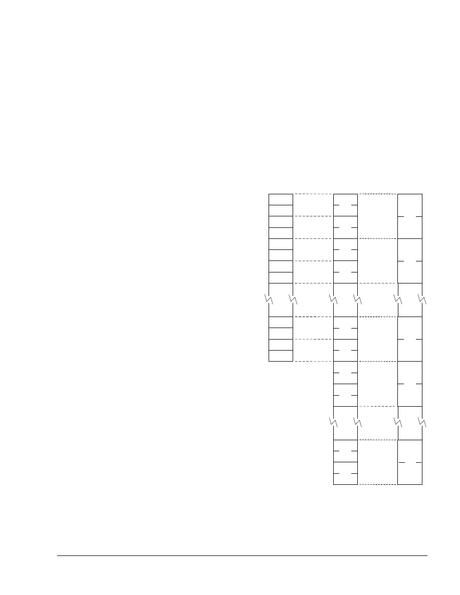
VFP Programming
ARM DUI 0379C
Copyright © 2007-2008, 2011 ARM. All rights reserved.
9-6
ID061811
Non-Confidential
9.4
Extension register bank mapping
The extension register bank used by VFP is distinct from the ARM register bank. The extension
register bank is a collection of registers which can be accessed as either 32-bit or 64-bit registers.
shows the three views of the extension register bank, and the overlap between the
different size registers. For example, the 64-bit register
D0
is an alias for two consecutive 32-bit
registers
S0
and
S1
.
The aliased views enables half-precision, single-precision, and double-precision values to
coexist in different non-overlapped registers at the same time.
You can also use the same overlapped registers to store half-precision, single-precision, and
double-precision values at different times.
Do not attempt to use overlapped 32-bit and 64-bit registers at the same time because it creates
meaningless results.
Figure 9-1 Extension register bank
The mapping between the registers is as follows:
•
S<2n>
maps to the least significant half of
D<n>
•
S<2n+1>
maps to the most significant half of
D<n>
.
D0
D3
D31
D30
S0
S1
S2
S3
S4
S5
S28
S29
S6
S7
S30
S31
...
D1
D2
D14
D15
D16
D17
...
Q0
Q1
Q7
Q8
Q15
...
...
...

VFP Programming
ARM DUI 0379C
Copyright © 2007-2008, 2011 ARM. All rights reserved.
9-7
ID061811
Non-Confidential
For example, you can access the least significant half of the elements in
D6
by referring to
S12
,
and the most significant half of the elements by referring to
S13
.
9.4.1
See also
Concepts
•
VFP views of the extension register bank on page 9-8
.

VFP Programming
ARM DUI 0379C
Copyright © 2007-2008, 2011 ARM. All rights reserved.
9-8
ID061811
Non-Confidential
9.5
VFP views of the extension register bank
In VFPv3 and VFPv3-FP16, you can view the extension register bank as:
•
Thirty-two 64-bit registers,
D0-D31
.
•
Thirty-two 32-bit registers,
S0-S31
. Only half of the register bank is accessible in this view.
•
A combination of registers from the above views.
In VFPv2, VFPv3-D16, and VFPv3-D16-FP16, you can view the extension register bank as:
•
Sixteen 64-bit registers,
D0-D15
.
•
Thirty-two 32-bit registers,
S0-S31
.
•
A combination of registers from the above views.
In VFP, 64-bit registers are called double-precision registers and can contain double-precision
floating-point values. 32-bit registers are called single-precision registers and can contain either
a single-precision or two half-precision floating-point values.
9.5.1
See also
Concepts
•
Extension register bank mapping on page 9-6
.

VFP Programming
ARM DUI 0379C
Copyright © 2007-2008, 2011 ARM. All rights reserved.
9-9
ID061811
Non-Confidential
9.6
Load values to VFP registers
In the VFPv3 instruction set there are instructions to load a limited range of floating-point
immediate values.
You can load any 64-bit integer, single-precision, or double-precision floating-point value from
a literal pool, in a single instruction, using the
VLDR
pseudo-instruction.
9.6.1
See also
Reference
Assembler Reference:
•
•

VFP Programming
ARM DUI 0379C
Copyright © 2007-2008, 2011 ARM. All rights reserved.
9-10
ID061811
Non-Confidential
9.7
Conditional execution of VFP instructions
In ARM state, you can use a condition code to control the execution of VFP instructions. The
instruction is executed conditionally, according to the status flags in the APSR, in exactly the
same way as almost all other ARM instructions.
In Thumb state on a Thumb-2 processor, you can use an
IT
instruction to set condition codes on
up to four following VFP instructions.
9.7.1
See also
Concepts
•
Condition code meanings on page 6-8
.

VFP Programming
ARM DUI 0379C
Copyright © 2007-2008, 2011 ARM. All rights reserved.
9-11
ID061811
Non-Confidential
9.8
Floating-point exceptions
The VFP extensions record the following floating-point exceptions in the FPSCR cumulative
flags:
Invalid operation
The exception is caused if the result of an operation has no mathematical value or
cannot be represented.
Division by zero
The exception is caused if a divide operation has a zero divisor and a dividend
that is not zero, an infinity or a NaN.
Overflow
The exception is caused if the absolute value of the result of an operation,
produced after rounding, is greater than the maximum positive normalized
number for the destination precision.
Underflow
The exception is caused if the absolute value of the result of an operation,
produced before rounding, is less than the minimum positive normalized number
for the destination precision, and the rounded result is inexact.
Inexact
The exception is caused if the result of an operation is not equivalent to the value
that would be produced if the operation were performed with unbounded
precision and exponent range.
Input denormal
The exception is caused if a denormalized input operand is replaced in the
computation by a zero.
In the Assembler Reference, in the descriptions of the instructions that can cause floating-point
exceptions, there is a subsection listing the exceptions. If there is no Floating-point exceptions
subsection in an instruction description, that instruction cannot cause any floating-point
exception.
9.8.1
See also
Concepts
•
Flush-to-zero mode on page 9-20
•
FPSCR, the floating-point status and control register on page 9-16
Reference
•
The Technical Reference Manual for your VFP coprocessor.

VFP Programming
ARM DUI 0379C
Copyright © 2007-2008, 2011 ARM. All rights reserved.
9-12
ID061811
Non-Confidential
9.9
VFP data types
Data type specifiers in VFP instructions consist of a letter indicating the type of data, usually
followed by a number indicating the width. They are separated from the instruction mnemonic
by a point.
shows the data types available in VFP instructions.
The datatype of the second (or only) operand is specified in the instruction.
Note
•
Most instructions have a restricted range of permitted data types. See the instruction pages
for details. However, the data type description is flexible:
—
If the description specifies I, you can also use S or U data types
—
If only the data size is specified, you can specify a type (S, U, or F)
—
If no data type is specified, you can specify a data type.
•
The
F16
data type is only available on systems that implement the half-precision
architecture extension.
9.9.1
See also
Concepts
•
Polynomial arithmetic over {0,1} on page 9-14
.
Table 9-1 VFP data types
16-bit
32-bit
64-bit
Unsigned integer
U16
U32
not available
Signed integer
S16
S32
not available
Floating-point number
F16
F32
(or
F
)
F64
(or
D
)

VFP Programming
ARM DUI 0379C
Copyright © 2007-2008, 2011 ARM. All rights reserved.
9-13
ID061811
Non-Confidential
9.10
Extended notation
The assembler implements an extension to the architectural VFP assembly syntax, called
extended notation. This extension allows you to include datatype information or scalar indexes
in register names. If you do this, you do not need to include the datatype or scalar index
information in every instruction.
Register names can be any of the following:
Untyped
The register name specifies the register, but not what datatype it contains, nor any
index to a particular scalar within the register.
Untyped with scalar index
The register name specifies the register, but not what datatype it contains, It
specifies an index to a particular scalar within the register.
Typed
The register name specifies the register, and what datatype it contains, but not any
index to a particular scalar within the register.
Typed with scalar index
The register name specifies the register, what datatype it contains, and an index
to a particular scalar within the register.
Use the
SN
and
DN
directives to create typed and scalar registers.
9.10.1
See also
Concepts
•
.
Reference
Assembler Reference:
•

VFP Programming
ARM DUI 0379C
Copyright © 2007-2008, 2011 ARM. All rights reserved.
9-14
ID061811
Non-Confidential
9.11
Polynomial arithmetic over {0,1}
The coefficients 0 and 1 are manipulated using the rules of Boolean arithmetic:
•
0 + 0 = 1 + 1 = 0
•
0 + 1 = 1 + 0 = 1
•
0 * 0 = 0 * 1 = 1 * 0 = 0
•
1 * 1 = 1.
That is, adding two polynomials over {0,1} is the same as a bitwise exclusive OR, and
multiplying two polynomials over {0,1} is the same as integer multiplication except that partial
products are exclusive-ORed instead of being added.
9.11.1
See also
Concepts
•
.

VFP Programming
ARM DUI 0379C
Copyright © 2007-2008, 2011 ARM. All rights reserved.
9-15
ID061811
Non-Confidential
9.12
VFP system registers
Three VFP system registers are accessible in all implementations of VFP:
•
FPSCR, the floating-point status and control register
•
FPEXC, the floating-point exception register
•
FPSID, the floating-point system ID register.
A particular implementation of VFP can have additional registers.
9.12.1
See also
Concepts
•
FPSCR, the floating-point status and control register on page 9-16
•
FPEXC, the floating-point exception register on page 9-18
•
FPSID, the floating-point system ID register on page 9-19
•
Read-Modify-Write procedure on page 5-28
Reference
•
Technical Reference Manual for your VFP Coprocessor.

VFP Programming
ARM DUI 0379C
Copyright © 2007-2008, 2011 ARM. All rights reserved.
9-16
ID061811
Non-Confidential
9.13
FPSCR, the floating-point status and control register
The
FPSCR
contains all the user-level VFP status and control bits. The bits are used as follows:
bits[31:28] Are the N, Z, C, and V flags. These are the VFP status flags. They cannot be used
to control conditional execution until they have been copied into the status flags
in the CPSR.
bit[27]
Not used.
bit[25]
Is the Default NaN (DN) mode control bit:
0
Disabled. NaN operands propagate through to the output of a
floating-point operation.
1
Enabled. Any operation involving one or more NaNs returns the
Default NaN.
bit[24]
Is the flush-to-zero mode control bit:
0
Flush-to-zero mode is disabled.
1
Flush-to-zero mode is enabled.
Flush-to-zero mode can provide greater performance, depending on your
hardware and software, at the expense of loss of range.
Note
Flush-to-zero mode must not be used when IEEE 754 compatibility is a
requirement.
bits[23:22] Control rounding mode as follows:
0b00
Round to Nearest (RN) mode.
0b01
Round towards Plus infinity (RP) mode.
0b10
Round towards Minus infinity (RM) mode.
0b11
Round towards Zero (RZ) mode.
bits[21:20]
STRIDE
is the distance between successive values in a vector. Stride is controlled
as follows:
0b00
STRIDE
= 1
0b11
STRIDE
= 2.
bits[18:16]
LEN
is the number of registers used by each vector. It is 1 + the value of
bits[18:16]:
0b000
LEN
= 1
...
…
0b111
LEN
= 8.
bits[15, 12:8] Are the exception trap enable bits:
IDE
input denormal exception enable
IXE
inexact exception enable
UFE
underflow exception enable
OFE
overflow exception enable
DZE
division by zero exception enable
IOE
invalid operation exception enable.
This document does not cover the use of floating-point exception trapping. For
information see the technical reference manual for the VFP coprocessor you are
using.

VFP Programming
ARM DUI 0379C
Copyright © 2007-2008, 2011 ARM. All rights reserved.
9-17
ID061811
Non-Confidential
bits[7, 4:0] Are the cumulative exception bits:
IDC
input denormal exception
IXC
inexact exception
UFC
underflow exception
OFC
overflow exception
DZC
division by zero exception
IOC
invalid operation exception.
Cumulative exception bits are set when the corresponding exception occurs. They
remain set until you clear them by writing directly to the
FPSCR
.
all other bits Are unused in the basic VFP specification. They can be used in particular
implementations. Do not modify these bits except in accordance with any use in
a particular implementation.
To change some bits without affecting other bits, use a read-modify-write procedure.
Note
The use of VFP vector mode is deprecated. Set
LEN
and
STRIDE
to 1.
9.13.1
See also
Concepts
•
Flush-to-zero mode on page 9-20
•
Floating-point exceptions on page 9-11
•
Conditional execution of VFP instructions on page 9-10
•
Condition code meanings on page 6-8
•
Vectors in the VFP extension register bank on page 9-25
•
Read-Modify-Write procedure on page 5-28
Reference
•
The Technical Reference Manual for your VFP coprocessor.

VFP Programming
ARM DUI 0379C
Copyright © 2007-2008, 2011 ARM. All rights reserved.
9-18
ID061811
Non-Confidential
9.14
FPEXC, the floating-point exception register
You can only access the
FPEXC
in privileged software execution. It contains the following bits:
bit[31]
Is the
EX
bit. You can read it in all VFP implementations. In some implementations
you might also be able to write to it.
If the value is 0, the only significant state in the VFP system is the contents of the
general-purpose registers plus
FPSCR
and
FPEXC
.
If the value is 1, you require implementation-specific information to save state.
bit[30]
Is the
EN
bit. You can read and write it in all VFP implementations.
If the value is 1, VFP (if present) is enabled and operate normally.
If the value is 0, VFP is disabled. When it is disabled, you can read or write the
FPSID
or
FPEXC
registers, but other VFP instructions are treated as Undefined
Instructions.
bits[29:0]
Might be used by particular implementations of VFP. You can use the VFP
instructions without accessing these bits.
You must not alter these bits except in accordance with their use in a particular
implementation.
To change some bits without affecting other bits, use a read-modify-write procedure.
9.14.1
See also
Concepts
•
Flush-to-zero mode on page 9-20
•
Conditional execution of VFP instructions on page 9-10
•
Condition code meanings on page 6-8
•
Read-Modify-Write procedure on page 5-28
Reference
•
The Technical Reference Manual for your VFP coprocessor.

VFP Programming
ARM DUI 0379C
Copyright © 2007-2008, 2011 ARM. All rights reserved.
9-19
ID061811
Non-Confidential
9.15
FPSID, the floating-point system ID register
The
FPSID
is a read-only register. You can read it to find out which implementation of the VFP
architecture your program is running on.
bit[31:24]
Implementor code
bit[23]
0 for hardware coprocessor, 1 for software implementation
bit[22:16]
Subarchitecture version number
bit[15:8]
Implementation defined part number
bit[7:4]
Implementation defined variant number
bit[3:0]
Implementation defined revision number.
9.15.1
See also
Concepts
•
VFP system registers on page 9-15
•
Read-Modify-Write procedure on page 5-28
Reference
•
The Technical Reference Manual for your VFP coprocessor or floating-point capable
processor.

VFP Programming
ARM DUI 0379C
Copyright © 2007-2008, 2011 ARM. All rights reserved.
9-20
ID061811
Non-Confidential
9.16
Flush-to-zero mode
Some implementations of VFP use support code to handle denormalized numbers. The
performance of such systems, in calculations involving denormalized numbers, is much less
than it is in normal calculations.
Flush-to-zero mode replaces denormalized numbers with 0. This does not comply with IEEE
754 arithmetic, but in some circumstances can improve performance considerably.
VFPv3 flush-to-zero preserves the sign bit. VFPv2 flush-to-zero flushes to +0.
9.16.1
See also
Concepts
•
When to use flush-to-zero mode on page 9-21
•
The effects of using flush-to-zero mode on page 9-22
•
Operations not affected by flush-to-zero mode on page 9-23
.

VFP Programming
ARM DUI 0379C
Copyright © 2007-2008, 2011 ARM. All rights reserved.
9-21
ID061811
Non-Confidential
9.17
When to use flush-to-zero mode
You must select flush-to-zero mode if all the following are true:
•
IEEE 754 compliance is not a requirement for your system
•
the algorithms you are using are such that they sometimes generate denormalized
numbers
•
your system uses support code to handle denormalized numbers
•
the algorithms you are using do not depend for their accuracy on the preservation of
denormalized numbers
•
the algorithms you are using do not generate frequent exceptions as a result of replacing
denormalized numbers with 0.
You can change between flush-to-zero and normal mode at any time, if different parts of your
code have different requirements. Numbers already in registers are not affected by changing
mode.
9.17.1
See also
Concepts
•
The effects of using flush-to-zero mode on page 9-22
•

VFP Programming
ARM DUI 0379C
Copyright © 2007-2008, 2011 ARM. All rights reserved.
9-22
ID061811
Non-Confidential
9.18
The effects of using flush-to-zero mode
With certain exceptions, flush-to-zero mode has the following effects on floating-point
operations:
•
A denormalized number is treated as 0 when used as an input to a floating-point operation.
The source register is not altered.
•
If the result of a single-precision floating-point operation, before rounding, is in the range
–2
–126
to +2
–126
, it is replaced by 0.
•
If the result of a double-precision floating-point operation, before rounding, is in the range
–2
–1022
to +2
–1022
, it is replaced by 0.
An inexact exception occurs whenever a denormalized number is used as an operand, or a result
is flushed to zero. Underflow exceptions do not occur in flush-to-zero mode.
9.18.1
See also
Concepts
•
Operations not affected by flush-to-zero mode on page 9-23
•

VFP Programming
ARM DUI 0379C
Copyright © 2007-2008, 2011 ARM. All rights reserved.
9-23
ID061811
Non-Confidential
9.19
Operations not affected by flush-to-zero mode
The following VFP operations can be carried out on denormalized numbers even in
flush-to-zero mode, without flushing the results to zero:
•
copy, absolute value, and negate (
VMOV
and
VMVN
)
•
duplicate (
VDUP
)
•
swap (
VSWP
)
•
load and store (
VLDR
and
VSTR
)
•
load multiple and store multiple (
VLDM
and
VSTM
)
•
transfer between extension registers and ARM general-purpose registers (
VMOV
).
9.19.1
See also
Concepts
•
The effects of using flush-to-zero mode on page 9-22
•
Flush-to-zero mode on page 9-20
Reference
Assembler Reference:
•
•
VLDM, VSTM, VPOP, and VPUSH on page 4-11
•
VABS, VNEG, and VSQRT on page 4-8
•
VMOV (between two ARM registers and an extension register) on page 4-12
•
VMOV (between one ARM register and single precision VFP) on page 4-13
.

VFP Programming
ARM DUI 0379C
Copyright © 2007-2008, 2011 ARM. All rights reserved.
9-24
ID061811
Non-Confidential
9.20
VFP vector mode
Usually the VFP core only works on a single register. However, many VFP arithmetic
instructions can also operate on vectors of up to eight single-precision or four double-precision
numbers, enabling Single Instruction Multiple Data (SIMD) parallelism.
In addition, the floating-point load and store instructions have multiple register forms, enabling
vectors to be transferred to and from memory easily.
Note
The use of VFP vector mode is deprecated.
9.20.1
See also
Concepts
•
Architecture support for VFP on page 9-3
•
Vectors in the VFP extension register bank on page 9-25
Reference
•
ARM Architecture Reference Manual,
http://infocenter.arm.com/help/topic/com.arm.doc.subset.arch.reference/index.html.
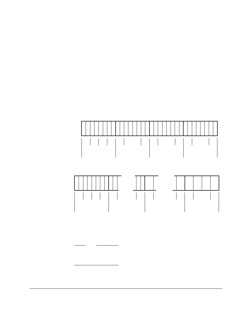
VFP Programming
ARM DUI 0379C
Copyright © 2007-2008, 2011 ARM. All rights reserved.
9-25
ID061811
Non-Confidential
9.21
Vectors in the VFP extension register bank
For vector operations, the VFP extension register bank can be viewed as a collection of smaller
banks. Each of these smaller banks is treated either as a bank of 8 single-precision registers or
as a bank of 4 double-precision registers.
In VFPv2, VFPv3-D16, and VFPv3-D16-FP16 the VFP extension register bank can be viewed
as a collection of:
•
four banks of single-precision registers, s0 to s7, s8 to s15, s16 to s23, and s24 to s31
•
four banks of double-precision registers, d0 to d3, d4 to d7, d8 to d11, and d12 to d15
•
any combination of single-precision and double-precision banks.
In VFPv3 and VFPv3-FP16, the VFP extension register bank can be viewed as a collection of:
•
four banks of single-precision registers, s0 to s7, s8 to s15, s16 to s23, and s24 to s31
•
Eight banks of double-precision registers, d0 to d3, d4 to d7, d8 to d11, d12 to d15, d16
to d19, d20 to d23, d24 to d27, and d28 to d31
•
any combination of single-precision and double-precision banks.
for further clarification.
Figure 9-2 VFPv2 register banks
Figure 9-3 VFPv3 register banks
A vector, in a VFP instruction, can use up to eight single-precision registers, or four
double-precision registers, from the same bank. The number of registers used by a vector is
controlled by the
LEN
bits in the
FPSCR
.
Note
The value of the
LEN
bits is not a sufficient condition to perform vector operations using VFP.
Whether a VFP operation is scalar, vector or mixed depends on which bank the specified
operand and destination registers are in.
Bank 0
Bank 1
Bank 2
Bank 3
d0 d1
d3 d4
d7 d8
d11 d12
d15
d2
...
...
...
s0s1
s7s8
s15s16
s23s24
s31
s2s3s4s5s6
...
...
...
Bank 0
Bank 1
Bank 3
d0 d1
d3 d4
d16
d27 d28
d15
d2
...
s0s1
s7s8
s31
s2s3s4s5s6
...
d31
Bank 7
Bank 4
Bank 6
...

VFP Programming
ARM DUI 0379C
Copyright © 2007-2008, 2011 ARM. All rights reserved.
9-26
ID061811
Non-Confidential
A vector can start from any register and wraps around to the beginning of the bank. The first
register used by an operand vector is the register that is specified as the operand in the individual
VFP instructions. The first register used by the destination vector is the register that is specified
as the destination in the individual VFP instructions.
9.21.1
See also
Concepts
•
FPSCR, the floating-point status and control register on page 9-16
•
VFP vector wrap-around on page 9-27
•
VFP vector stride on page 9-28
•
Restriction on vector length on page 9-29
•
Control of scalar, vector, and mixed operations on page 9-30
.

VFP Programming
ARM DUI 0379C
Copyright © 2007-2008, 2011 ARM. All rights reserved.
9-27
ID061811
Non-Confidential
9.22
VFP vector wrap-around
If the vector extends beyond the end of a bank, it wraps around to the beginning of the same
bank, for example:
•
a vector of length 6 starting at s5 is {s5, s6, s7, s0, s1, s2}
•
a vector of length 3 starting at s15 is {s15, s8, s9}
•
a vector of length 4 starting at s22 is {s22, s23, s16, s17}
•
a vector of length 2 starting at d7 is {d7, d4}
•
a vector of length 3 starting at d10 is {d10, d11, d8}.
A vector cannot contain registers from more than one bank.
9.22.1
See also
Concepts
•
FPSCR, the floating-point status and control register on page 9-16
•
Vectors in the VFP extension register bank on page 9-25
•
VFP vector stride on page 9-28
•

VFP Programming
ARM DUI 0379C
Copyright © 2007-2008, 2011 ARM. All rights reserved.
9-28
ID061811
Non-Confidential
9.23
VFP vector stride
Vectors can occupy consecutive registers or they can occupy alternate registers. This is
controlled by the
STRIDE
bits in the
FPSCR
. For example:
•
a vector of length 3, stride 2, starting at s1, is {s1, s3, s5}
•
a vector of length 4, stride 2, starting at s6, is {s6, s0, s2, s4}
•
a vector of length 2, stride 2, starting at d1, is {d1, d3}.
•
a vector of length 4, stride 1, starting at d0, is {d0, d1, d2, d3}.
9.23.1
See also
Concepts
•
FPSCR, the floating-point status and control register on page 9-16
•
Vectors in the VFP extension register bank on page 9-25
•
VFP vector wrap-around on page 9-27
•

VFP Programming
ARM DUI 0379C
Copyright © 2007-2008, 2011 ARM. All rights reserved.
9-29
ID061811
Non-Confidential
9.24
Restriction on vector length
A vector cannot use the same register twice. Enabling for vector wrap-around, this means that
you cannot have:
•
a single-precision vector with length > 4 and stride = 2
•
a double-precision vector with length > 4 and stride = 1
•
a double-precision vector with length > 2 and stride = 2.
9.24.1
See also
Concepts
•
FPSCR, the floating-point status and control register on page 9-16
•
Vectors in the VFP extension register bank on page 9-25
•

VFP Programming
ARM DUI 0379C
Copyright © 2007-2008, 2011 ARM. All rights reserved.
9-30
ID061811
Non-Confidential
9.25
Control of scalar, vector, and mixed operations
You can use VFP arithmetic instructions to operate on:
•
scalars
•
vectors
•
scalars and vectors together.
Use the
LEN
bits in the
FPSCR
to control the length of vectors. When
LEN
is 1 all VFP operations
are scalar.
When
LEN
is greater than 1, the VFP operation can be scalar, vector or mixed. The behavior of
VFP arithmetic operations depends on which register bank the destination and operand registers
are in.
The first bank of registers, s0 to s7 or d0 to d3 and the fifth bank of registers d16 to d19 are scalar
banks. All other banks are vector banks. A vector operation or mixed operation is one where the
destination register is in one of the vector banks.
Given instructions of the following general forms:
Op Fd,Fn,Fm
Op Fd,Fm
where:
Op
is the VFP instruction
Fd
is the destination register
Fn
is an operand register
Fm
is the only or second operand register
the behavior of the operation is as follows:
•
If
Fd
is in the first or fifth bank of registers then the operation is scalar.
•
If
Fm
is in the first or fifth bank of registers, but
Fd
is not, then the operation is mixed.
•
If neither
Fd
nor
Fm
are in the first or fifth bank of registers, the operation is vector.
In scalar operations,
Op
acts on the value in
Fm
, and the value in
Fn
if present. The result is placed
in
Fd
.
In vector operations,
Op
acts on the values in the vector starting at
Fm
, together with the values
in the vector starting at
Fn
if present. The results are placed in the vector starting at
Fd
.
In mixed operations, with a single operand,
Op
acts on the single value in
Fm
and
LEN
copies of
the result are placed in the vector starting at
Fd
.
In mixed operations, with two operands,
Op
acts on the single value in
Fm
, together with the
values in the vector starting at
Fn
. The results are placed in the vector starting at
Fd
.
9.25.1
See also
Concepts
•
FPSCR, the floating-point status and control register on page 9-16
•
Vectors in the VFP extension register bank on page 9-25
•
VFP vector wrap-around on page 9-27
•
VFP vector stride on page 9-28
•

VFP Programming
ARM DUI 0379C
Copyright © 2007-2008, 2011 ARM. All rights reserved.
9-31
ID061811
Non-Confidential
9.26
VFP directives and vector notation
This applies only to
armasm
. The inline assemblers in the C and C++ compilers do not accept
these directives or vector notation.
The use of VFP vector mode is deprecated, and vector notation is not supported in UAL. To use
vector notation, you must use the pre-UAL VFP mnemonics. See
for details. You can mix pre-UAL VFP mnemonics and UAL VFP mnemonics.
You can make assertions about VFP vector lengths and strides in your code, and have them
checked by the assembler. See:
•
•
.
If you use
VFPASSERT
directives, you must specify vector details in all VFP data processing
instructions written using pre-UAL mnemonics. The vector notation is described in
. If you do not use
VFPASSERT
directives you must not use this notation.

VFP Programming
ARM DUI 0379C
Copyright © 2007-2008, 2011 ARM. All rights reserved.
9-32
ID061811
Non-Confidential
9.27
Pre-UAL VFP mnemonics
Where UAL mnemonics use
.F32
to specify single-precision data, pre-UAL mnemonics use
S
appended to the instruction mnemonic. For example,
VABS.F32
was
FABSS
.
Where UAL mnemonics use
.F64
to specify double-precision data, pre-UAL mnemonics use
D
appended to the instruction mnemonic. For example,
VCMPE.F64
was
FCMPED
.
shows the pre-UAL mnemonics of those instructions that are affected by VFP vector
mode. All other VFP instructions are always scalar regardless of the settings of
LEN
and
STRIDE
.
Table 9-2 Pre-UAL VFP mnemonics
UAL mnemonic
Equivalent pre-UAL mnemonic
VABS
FABS
VADD
FADD
VDIV
FDIV
VMLA
FMAC
VMLS
FNMAC
VMOV
(immediate)
FCONST
a
a. The immediate in
VMOV
(immediate) is the floating-point number you want to load. The
immediate in
FCONST
is the number encoded in the instruction to produce the floating-point
number you want to load. See
Immediate values in FCONST on page 9-33
for details.
VMOV
(register)
FCPY
VMUL
FMUL
VNEG
FNEG
VNMLA
FNMSC
VNMLS
FMSC
VNMUL
FNMUL
VSQRT
FSQRT
VSUB
FSUB

VFP Programming
ARM DUI 0379C
Copyright © 2007-2008, 2011 ARM. All rights reserved.
9-33
ID061811
Non-Confidential
9.27.1
Immediate values in FCONST
shows the floating-point values you can load using
FCONST
. Trailing zeroes are omitted
for clarity. The immediate value you must put in the
FCONST
instruction is the decimal
representation of the binary number
abcdefgh
, where:
a
is 0 for positive numbers, or 1 for negative numbers
bcd
is shown in the column headings
efgh
is shown in the row headings.
Alternatively, you can use
0x
followed by the hexadecimal representation.
Table 9-3 Floating-point values for use with FCONST
bcd
000
001
010
011
100
101
110
111
efgh
0000
2.0
4.0
8.0
16.0
0.125
0.25
0.5
1.0
0001
2.125
4.25
8.5
17.0
0.1328125
0.265625
0.53125
1.0625
0010
2.25
4.5
9.0
18.0
0.140625
0.28125
0.5625
1.125
0011
2.375
4.75
9.5
19.0
0.1484375
0.296875
0.59375
1.1875
0100
2.5
5.0
10.0
20.0
0.15625
0.3125
0.625
1.25
0101
2.625
5.25
10.5
21.0
0.1640625
0.328125
0.65625
1.3125
0110
2.75
5.5
11.0
22.0
0.171875
0.34375
0.6875
1.375
0111
2.875
5.75
11.5
23.0
0.1796875
0.359375
0.71875
1.4375
1000
3.0
6.0
12.0
24.0
0.1875
0.375
0.75
1.5
1001
3.125
6.25
12.5
25.0
0.1953125
0.390625
0.78125
1.5625
1010
3.25
6.5
13.0
26.0
0.203125
0.40625
0.8125
1.625
1011
3.375
6.75
13.5
27.0
0.2109375
0.421875
0.84375
1.6875
1100
3.5
7.0
14.0
28.0
0.21875
0.4375
0.875
1.75
1101
3.625
7.25
14.5
29.0
0.2265625
0.453125
0.90625
1.8125
1110
3.75
7.5
15.0
30.0
0.234375
0.46875
0.9375
1.875
1111
3.875
7.75
15.5
31.0
0.2421875
0.484375
0.96875
1.9375

VFP Programming
ARM DUI 0379C
Copyright © 2007-2008, 2011 ARM. All rights reserved.
9-34
ID061811
Non-Confidential
9.28
Vector notation
In pre-UAL VFP data processing instructions, specify vectors of VFP registers using angle
brackets:
•
sn
is a single-precision scalar register
n
.
•
sn <>
is a single-precision vector whose length and stride are given by the current vector
length and stride, as defined by
VFPASSERT VECTOR
. The vector starts at register
n
.
•
sn <L>
is a single-precision vector of length L, stride 1. The vector starts at register
n
.
•
sn <L:S>
is a single-precision vector of length
L
, stride
S
. The vector starts at register
n
.
•
dn
is a double-precision scalar register
n
.
•
dn <>
is a double-precision vector whose length and stride are given by the current vector
length and stride, as defined by
VFPASSERT VECTOR
. The vector starts at register
n
.
•
dn <L>
is a double-precision vector of length L, stride 1. The vector starts at register
n
.
•
dn <L:S>
is a double-precision vector of length
L
, stride
S
. The vector starts at register
n
.
You can use this vector notation with names defined using the
DN
and
SN
directives.
You must not use this vector notation in the
DN
and
SN
directives themselves.
9.28.1
See also
Concepts
•
.
Reference
Assembler Reference:
•

VFP Programming
ARM DUI 0379C
Copyright © 2007-2008, 2011 ARM. All rights reserved.
9-35
ID061811
Non-Confidential
9.29
VFPASSERT SCALAR
The
VFPASSERT SCALAR
directive informs the assembler that following VFP instructions are in
scalar mode. This forces the instruction syntax to be scalar.
9.29.1
Syntax
VFPASSERT SCALAR
9.29.2
Usage
Use the
VFPASSERT SCALAR
directive to mark the end of any block of code where the VFP mode
is
VECTOR
.
Place the
VFPASSERT SCALAR
directive immediately after the instruction where the change occurs.
This is usually an
FMXR
instruction, but might be a
BL
instruction.
If a function expects the VFP to be in vector mode on exit, place a
VFPASSERT SCALAR
directive
immediately after the last instruction. Such a function would not be AAPCS compliant.
Note
This directive does not generate any code. It is only an assertion by the programmer. The
assembler produces error messages if any such assertions are inconsistent with each other, or
with any vector notation in VFP data processing instructions.
The assembler faults vector notation in VFP data processing instructions following a
VFPASSERT
SCALAR
directive, even if the vector length is 1.
9.29.3
Example
VFPASSERT SCALAR ; scalar mode
faddd d4, d4, d0 ; okay
fadds s4<3>, s0, s8<3> ; ERROR, vector in scalar mode
fabss s24<1>, s28<1> ; ERROR, vector in scalar mode
; (even though length==1)
9.29.4
See also
Reference
•
•
•
Procedure Call Standard for the ARM Architecture,
http://infocenter.arm.com/help/topic/com.arm.doc.ihi0042-/index.html.

VFP Programming
ARM DUI 0379C
Copyright © 2007-2008, 2011 ARM. All rights reserved.
9-36
ID061811
Non-Confidential
9.30
VFPASSERT VECTOR
The
VFPASSERT VECTOR
directive informs the assembler that following VFP instructions are in
vector mode. It can also specify the length and stride of the vectors.
9.30.1
Syntax
VFPASSERT VECTOR{<{n{:s}}>}
where:
n
is the vector length, 1-8.
s
is the vector stride, 1-2.
9.30.2
Usage
Use the
VFPASSERT VECTOR
directive to mark the start of a block of instructions where the VFP
mode is
VECTOR
, and to mark changes in the length or stride of vectors.
Place the
VFPASSERT VECTOR
directive immediately after the instruction where the change occurs.
This is usually an
FMXR
instruction, but might be a
BL
instruction.
If a function expects the VFP to be in vector mode on entry, place a
VFPASSERT VECTOR
directive
immediately before the first instruction. Such a function would not be AAPCS compliant.
Note
This directive does not generate any code. It is only an assertion by the programmer. The
assembler produces error messages if any such assertions are inconsistent with each other, or
with any vector notation in VFP data processing instructions.
9.30.3
Example
VMRS r10,FPSCR ; UAL mnemonic - could be FMRX instead.
BIC r10,r10,#0x00370000
ORR r10,r10,#0x00020000 ; set length = 3, stride = 1
VMSR FPSCR,r10
VFPASSERT VECTOR ; assert vector mode, unspecified length & stride
faddd d4, d4, d0 ; ERROR, scalar in vector mode
fadds s16<3>, s0, s8<3> ; okay
fabss s24<1>, s28<1> ; wrong length, but not faulted (unspecified)
VMRS r10,FPSCR
BIC r10,r10,#0x00370000
ORR r10,r10,#0x00030000 ; set length = 4, stride = 1
VMSR FPSCR,r10
VFPASSERT VECTOR<4> ; assert vector mode, length 4, stride 1
fadds s24<4>, s0, s8<4> ; okay
fabss s24<2>, s24<2> ; ERROR, wrong length
VMRS r10,FPSCR
BIC r10,r10,#0x00370000
ORR r10,r10,#0x00130000 ; set length = 4, stride = 2
VMSR FPSCR,r10
VFPASSERT VECTOR<4:2> ; assert vector mode, length 4, stride 2
fadds s8<4>, s0, s16<4> ; ERROR, wrong stride because omitting the stride
; causes a default stride of 1.
fabss s16<4:2>, s28<4:2> ; okay
fadds s8<>, s2, s16<> ; okay (s8 and s16 both have
; length 4 and stride 2.
; s2 is scalar.)

VFP Programming
ARM DUI 0379C
Copyright © 2007-2008, 2011 ARM. All rights reserved.
9-37
ID061811
Non-Confidential
9.30.4
See also
Concepts
•
Reference
•
•
•
Procedure Call Standard for the ARM Architecture,
http://infocenter.arm.com/help/topic/com.arm.doc.ihi0042-/index.html.
Document Outline
- ARM Compiler toolchain v4.1 for µVision Using the Assembler
- Contents
- Conventions and feedback
- Overview of the Assembler
- Overview of the ARM Architecture
- 3.1 About the ARM architecture
- 3.2 ARM, Thumb, and ThumbEE instruction sets
- 3.3 Changing between ARM, Thumb, and ThumbEE state
- 3.4 Processor modes, and privileged and unprivileged software execution
- 3.5 Processor modes in ARMv6-M and ARMv7-M
- 3.6 VFP coprocessor
- 3.7 ARM registers
- 3.8 General-purpose registers
- 3.9 Register accesses
- 3.10 Predeclared core register names
- 3.11 Predeclared extension register names
- 3.12 Predeclared coprocessor names
- 3.13 Program Counter
- 3.14 Application Program Status Register
- 3.15 The Q flag
- 3.16 Current Program Status Register
- 3.17 Saved Program Status Registers (SPSRs)
- 3.18 Instruction set overview
- 3.19 Media processing instructions
- 3.20 Access to the inline barrel shifter
- Structure of Assembly Language Modules
- Writing ARM Assembly Language
- 5.1 Unified Assembler Language
- 5.2 Subroutines calls
- 5.3 Load immediates into registers
- 5.4 Load immediate values using MOV and MVN
- 5.5 Load 32-bit values to a register using MOV32
- 5.6 Load immediate 32-bit values to a register using LDR Rd, =const
- 5.7 Literal pools
- 5.8 Load addresses into registers
- 5.9 Load addresses to a register using ADR
- 5.10 Load addresses to a register using ADRL
- 5.11 Load addresses to a register using LDR Rd, =label
- 5.12 Other ways to Load and store registers
- 5.13 Load and store multiple register instructions
- 5.14 Load and store multiple instructions available in ARM and Thumb
- 5.15 Stack implementation using LDM and STM
- 5.16 Stack operations for nested subroutines
- 5.17 Block copy with LDM and STM
- 5.18 Memory accesses
- 5.19 Read-Modify-Write procedure
- 5.20 Optional hash
- 5.21 Use of macros
- 5.22 Test-and-branch macro example
- 5.23 Unsigned integer division macro example
- 5.24 Instruction and directive relocations
- 5.25 Symbol versions
- 5.26 Frame directives
- 5.27 Exception tables and Unwind tables
- 5.28 Assembly language changes after RVCTv2.1
- Condition Codes
- 6.1 Conditional instructions
- 6.2 Conditional execution in ARM state
- 6.3 Conditional execution in Thumb state
- 6.4 Updates to the ALU status flags
- 6.5 Condition code suffixes
- 6.6 Condition code meanings
- 6.7 Benefits of using conditional execution
- 6.8 Illustration of the benefits of using conditional instructions
- 6.8.1 Example of conditional execution using branches in ARM code
- 6.8.2 Example of conditional execution using conditional instructions in ARM code
- 6.8.3 Example of conditional execution using conditional instructions in Thumb code
- 6.8.4 Example of conditional execution code using branches in Thumb code
- 6.8.5 See also
- 6.9 Optimization for execution speed
- Using the Assembler
- 7.1 Assembler command line syntax
- 7.2 Assembler commands listed in groups
- 7.3 Specify command line options with an environment variable
- 7.4 Using stdin to input source code to the assembler
- 7.5 Built-in variables and constants
- 7.6 Versions of armasm
- 7.7 Diagnostic messages
- 7.8 Interlocks diagnostics
- 7.9 IT block generation
- 7.10 Thumb branch target alignment
- 7.11 Thumb code size diagnostics
- 7.12 ARM and Thumb instruction portability diagnostics
- 7.13 Instruction width
- 7.14 2 pass assembler diagnostics
- 7.15 Using the C preprocessor
- 7.16 Address alignment
- 7.17 Instruction width selection in Thumb
- Symbols, Literals, Expressions, and Operators
- 8.1 Symbol naming rules
- 8.2 Variables
- 8.3 Numeric constants
- 8.4 Assembly time substitution of variables
- 8.5 Register-relative and PC-relative expressions
- 8.6 Labels
- 8.7 Labels for PC-relative addresses
- 8.8 Labels for register-relative addresses
- 8.9 Labels for absolute addresses
- 8.10 Local labels
- 8.11 Syntax of local labels
- 8.12 String expressions
- 8.13 String literals
- 8.14 Numeric expressions
- 8.15 Numeric literals
- 8.16 Floating-point literals
- 8.17 Logical expressions
- 8.18 Logical literals
- 8.19 Unary operators
- 8.20 Binary operators
- 8.21 Multiplicative operators
- 8.22 String manipulation operators
- 8.23 Shift operators
- 8.24 Addition, subtraction, and logical operators
- 8.25 Relational operators
- 8.26 Boolean operators
- 8.27 Operator precedence
- 8.28 Difference between operator precedence in armasm and C
- VFP Programming
- 9.1 Architecture support for VFP
- 9.2 Half-precision extension
- 9.3 Fused Multiply-Add extension
- 9.4 Extension register bank mapping
- 9.5 VFP views of the extension register bank
- 9.6 Load values to VFP registers
- 9.7 Conditional execution of VFP instructions
- 9.8 Floating-point exceptions
- 9.9 VFP data types
- 9.10 Extended notation
- 9.11 Polynomial arithmetic over {0,1}
- 9.12 VFP system registers
- 9.13 FPSCR, the floating-point status and control register
- 9.14 FPEXC, the floating-point exception register
- 9.15 FPSID, the floating-point system ID register
- 9.16 Flush-to-zero mode
- 9.17 When to use flush-to-zero mode
- 9.18 The effects of using flush-to-zero mode
- 9.19 Operations not affected by flush-to-zero mode
- 9.20 VFP vector mode
- 9.21 Vectors in the VFP extension register bank
- 9.22 VFP vector wrap-around
- 9.23 VFP vector stride
- 9.24 Restriction on vector length
- 9.25 Control of scalar, vector, and mixed operations
- 9.26 VFP directives and vector notation
- 9.27 Pre-UAL VFP mnemonics
- 9.28 Vector notation
- 9.29 VFPASSERT SCALAR
- 9.30 VFPASSERT VECTOR
Wyszukiwarka
Podobne podstrony:
DUI0473C using the arm assembler
11 3 4 6 Lab Using the CLI to Gather Network?vice Information
Roszak, Rewers, Pliszka USING THE 3D
Barron Using the standard on objective measures for concert auditoria, ISO 3382, to give reliable r
11 3 4 6 Lab Using the CLI to Gather Network (2)
Using the PSpice Library Translator
A ZVS PWM Inverter With Active Voltage Clamping Using the Reverse Recovery Energy of the Diodes
Developing your STM32VLDISCOVERY application using the MDK ARM
Developing your STM32VLDISCOVERY application using the Atollic TrueSTUDIO
Ch5 Using the Tutorials
8 1 2 7 Lab Using the Windows?lculator with Network?dresses
Guide to using the tests
Introduction to business modeling using the UML
guide to using the tests Notatek pl
Assessment of Borderline Pathology Using the Inventory of Interpersonal Problems Circumplex Scales (
Using the Mouse
Rampant Tech Press Using the Oracle oradebug Utility Debugging Oracle Applications eBook DDU
więcej podobnych podstron