12
Fuzzy Logic in Automotive Engineering
Constantin von Altrock
28
Self-Evolving Systems and Liability
Who’s Responsible for a System’s Growing Pains?
Rod Taber
32
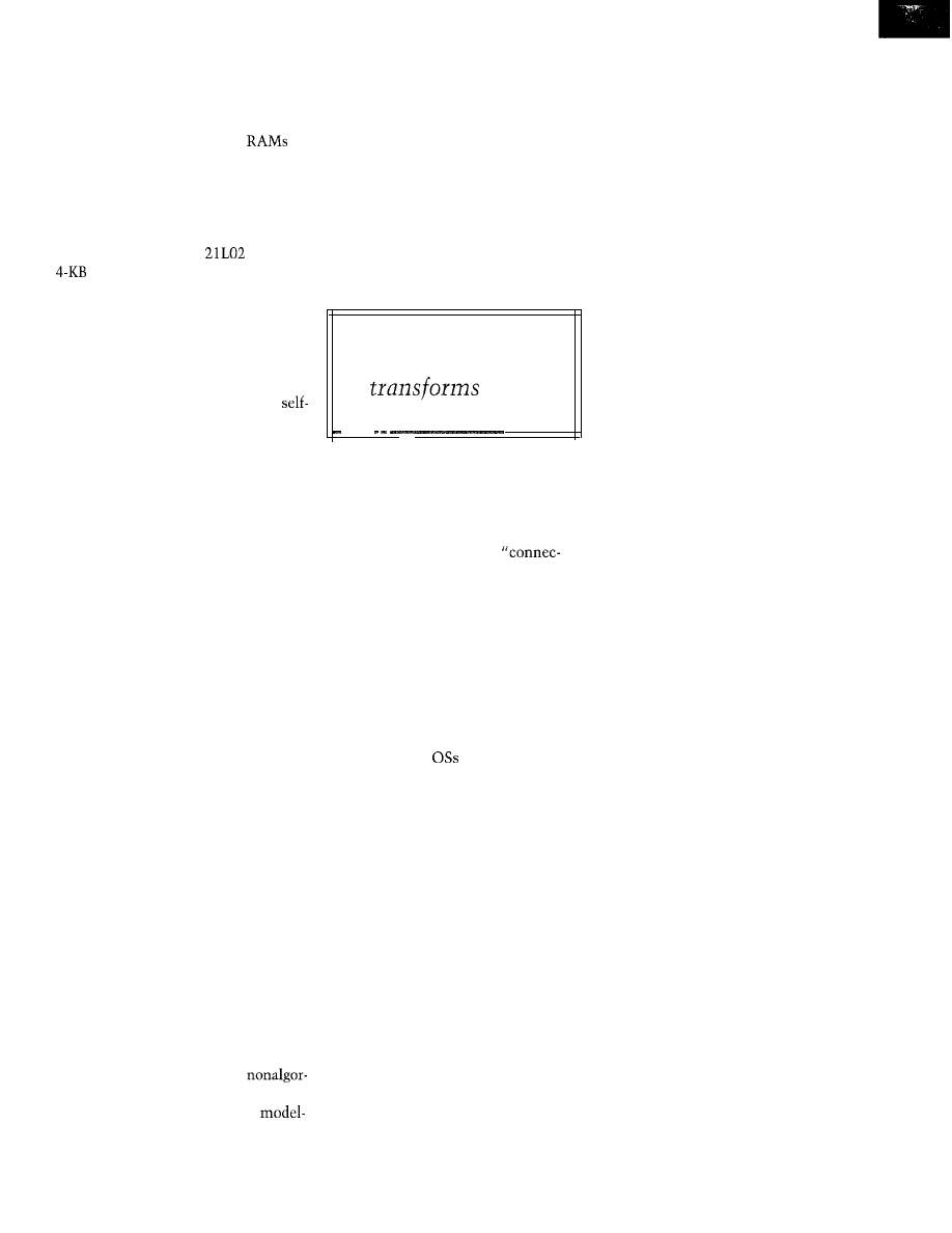
Fuzzy Concepts Using C
Walter Banks
q
MC68030
Workstation
Part 3: Cross-Development Environment and Downloading
Cyliax
74
From the Bench
Nonintrusive Interfacing-Using Kid Gloves
Jeff Bachiochi
78
q
Silicon Update
USB Micro
Tom Can
New Product News
edited by Harv Weiner
Advertiser’s Index
Your Unbiased Advocate
edited by Harv Weiner
Windows CE for Embedded Applications
Edward Steinfeld
Remote Internet Data Logging and Sensing
Cyliax
Interfaces and GUI-Building Packages
Part 1: Web-Accessible Virtual Front Panel
Fred Eady
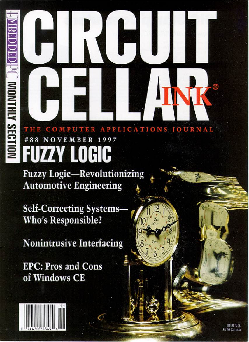
Circuit Cellar
Issue 88 November 1997

HDTV AND MONITOR LIMITATIONS
I enjoyed Do-While Jones’ “HDTV-The New Digital
Direction”
86). He took on a large subject!
The section on monitor limitations, however, contains
a significant technical error. The author confused the
vertical phosphor stripes and slotted shadow mask of
Trinitron-style CRTs with the rare and technically chal-
lenging Beam Index CRT.
In a Trinitron CRT, there are still three electron
beams-one each for R, G, and B. A slotted shadow mask
[or aperture grill) is located behind the phosphors. Since
the slots extend from the top to bottom on the CRT, Sony
uses stabilizer wires to keep the metal strips from vibrat-
ing, which causes the horizontal-line artifacts seen on
Trinitron monitors. As is typical of all shadow masks, its
location behind the screen allows only the “correct”
electron beam to strike its associated phosphor stripe.
Maybe you’ve read about “One Gun” Trinitrons.
There’s some truth to it, but it’s mostly marketing. After
the three electron beams are formed by three electron
guns, the beams are focused and shaped by a single set of
electronic lenses. The larger electrostatic “lenses” pro-
vide a better spot quality as the beams are deflected (see
and
In all shadow-mask CRTs, the vast majority of the
electron-beam energy is lost in the shadow mask. The
Beam Index CRT achieves high brightness by eliminating
the shadow mask and allowing all electron-beam energy
to excite the phosphors. As Do-While described, a single
beam is time-division multiplexed between R, G, and B.
Another stripe synchronizes the multiplexer.
It would be impractical to create a horizontal deflec-
tion system with adequate linearity to maintain the RGB
multiplexing sync open loop. Some sync implementa-
tions use high-conductivity aluminum stripes between
the B and R phosphor stripes, so a pulse in anode current
indicates the start of a new RGB sequence. Other imple-
mentations use a thin stripe of UV-emitting phosphor,
with a UV detector incorporated in the back of the CRT
bottle to generate the sync signal. Due to their cost and
complexity, these systems have only found application in
avionic cockpit displays that must be sunlight readable.
Recently, this market has been taken over by
so Beam Index CRTs may be nothing more than a
historical curiosity. There isn’t much on the Web about
Beam Index CRTs, but I found an abstract titled “Techni-
cal challenges of high-voltage power supplies for a mod-
ern beam index CRT electronic display” at the
technical library.
As for ball-park displays, what about the famous Sony
Jumbotron
or Mitsubishi’s
Diamond Vision system (www.amasis.com/
diamondvision/technical.html).
Overall, I don’t think HDTV requires a breakthrough
in monitor technology. I’ve seen HDTV demos at
shows for several years. My desktop monitor produces a
1600 x 1200 pixel image. If the CRT was made in the
aspect ratio, it could easily display 1920 x 1080.
Consider the price of 17” monitors. They used to be
about $1200, but now you can buy a decent one for under
$600. Once volume production kicks in, I think prices will
be comparable to today’s high-end consumer-TV costs.
Tim Godfrey
tgodfreyQdigocean.com
HDTV FREQUENCY FACTS
I enjoyed Do-While Jones’ recent article
The New Digital Direction,”
INK 86).
But, it left me with
some questions. What frequencies and how many chan-
nels have been allocated for HDTV broadcasting, and
how will the current frequencies be used after the are no
longer used for commercial broadcast?
Thanks for an excellent article.
Joe Kihm
Existing UHF TV frequencies have been allocated. I
don’t have the exact number, but I’ve seen lists of fre-
quencies assigned to various existing broadcast stations.
I’m sure there are enough for all existing TV stations.
Everybody’s wondering how the current frequencies
will be used! The TV stations want to go back to the
VHF band because UHF is short range and doesn’t pen-
etrate trees very well. The FCC, and perhaps cable and
satellite operators, want to keep the broadcast stations
in the UHF band to limit broadcast coverage.
The FCC prefers many little stations to just a few
superstations because bandwidth is limited, and they
want to give it to as
people as possible. Cable and
satellite operators, of course, would like to sell signals to
people who can’t receive them directly. The fewer people
who can receive them directly, the bigger the customer
base. There could be a bitter political fight about this.
Do- While
6
Issue
88 November 1997
Circuit Cellar INK@
Edited by Harv Weiner
SERVO MOTION CONTROL
The ADMC300 integrates a
fixed-point
DSP core and a complete set of peripherals optimized
for high-performance motor control. These functions
comprise five dedicated analog input channels (includ-
ing five
a three-phase 12-bit PWM generator,
encoder interface, and an event timer block. The
vice also features two
PWM auxiliary timers,
expansion capability via two serial ports, and a
digital I/O port.
Additional features include an internal 4K x
word program RAM and
x 16-bit word data RAM,
which can be loaded from an external ROM via the
serial port. The ADMC300 also features a 2K x 24-bit
word program ROM, including a monitor program tha
adds software debugging features through the serial
port.
program ROM offers commonly used fixed
motor-control algorithm functions and several options
for serially loading the device.
The ADMC300 provides smooth torque control
over the entire speed range. Control functions required
by high-performance servo drives include stall,
fast dynamic response, and accurate position and speed
control with excellent regulation. By using sigma-delta
conversion technology, it’s possible to add high-resolu-
tion
(1 to
A/D conversions to the same silicon
as a high-speed DSP core, while reducing the
aliasing
requirements of the system.
The ADMC300 sells for $9.50 in quantities of
100,000.
Analog Devices
One Technology Way
l
Not-wood, MA 02062-9106
(617) 329-4700
l
Fax: (617)
SINGLE-BOARD COMPUTER
The Tiger Byte-51 is a miniature SBC based on the 8051 microcontroller fam-
ily. Measuring just 1.65” x
the board
the
microcontroller
running at speeds up to 24 MHz.
The
has 8 KB of program flash memory for on-chip program
A major advantage is the chip’s mechanism for in-system programming.
An SPI synchronous serial port lets user software be downloaded into flash
memory. Any PC with a parallel port can bc used to program the chip by
interfacing with the board’s IO-pin connector.
The board features a
data EEPROM, RS-232 or RS-485 serial port
buffering, a DS 1233
device,
voltage regulator,
typing area, and access to all CPU lines. Power requirements are an unregu-
lated source of 9 VDC.
The Tiger Byte-5 1 is priced at $59. A kit that includes the Tiger
51, a PC cable, and PC Programmer Software
for $79.
Allen Systems
2346
Rd.
l
Columbus, OH 43221
(614) 488-7122
Issue 88 November 1997
Circuit Cellar
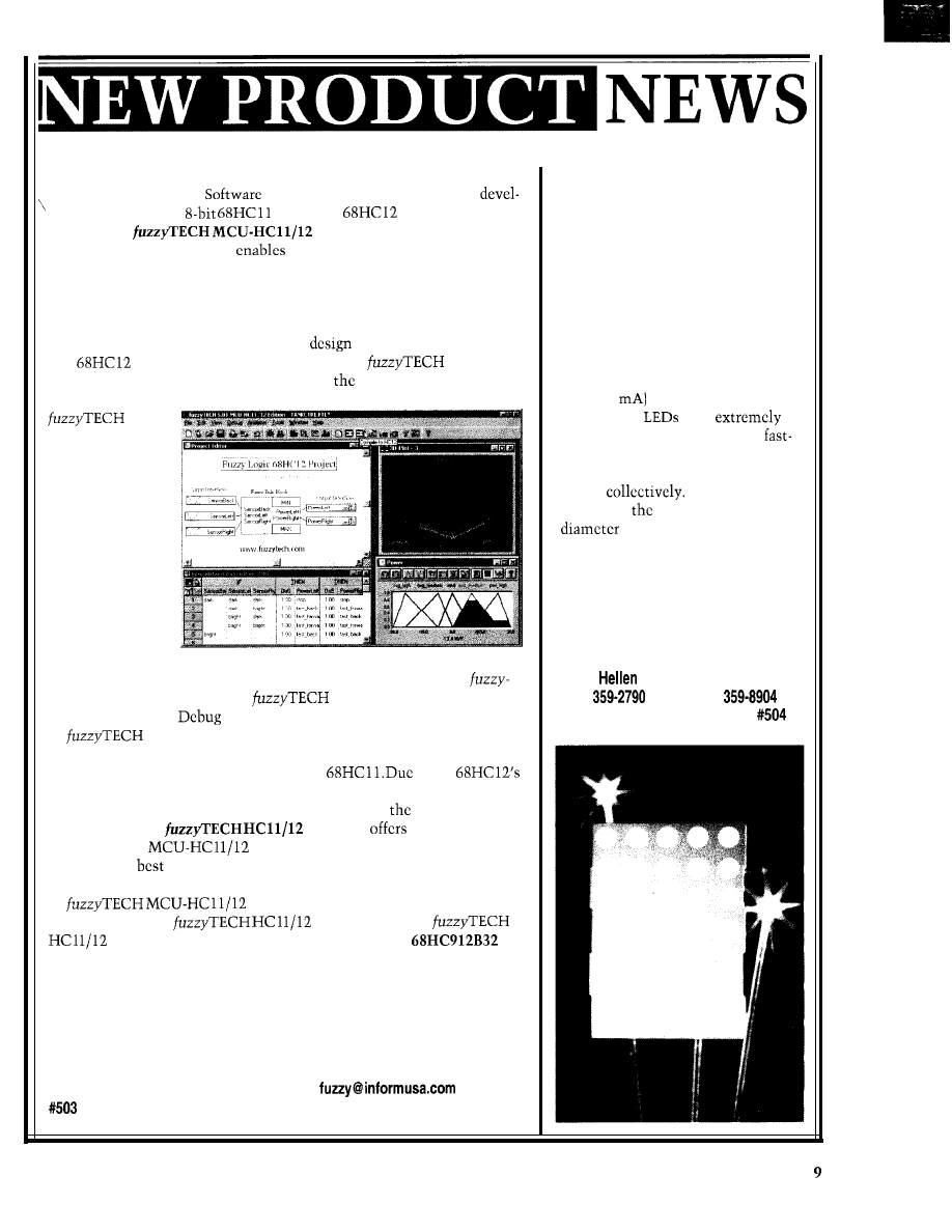
FUZZY-LOGIC TOOLS
Motorola and Inform
have announced new fuzzy-logic
opment tools for the
and 16-bit
microcontroller
families. The
Edition
simplifies program-
ming, reduces code size, and
faster code execution.
RGB DOT-MATRIX LED
The 68HC 12 is the first general-purpose microcontroller family with
dedicated fuzzy-logic instructions. Its price/performance ratio enables
innovative solutions in diverse applications (e.g., hard-disk design, auto-
motive ABS and ignition systems, as well as routing and cell switching).
A
5 x 7 dot-matrix display
with
full-color RGB output is available
from Lumex. The 2.09” high display
brings full animation and color capa-
bilities to a wide range of messaging
and display applications.
Inform provides complete fuzzy-logic
software for all 68HC 11
and
derivatives. At the push of a button,
generates
the fuzzy-logic system as assembly code for
target microcontroller.
On the 68HC 11,
emu-
lates the entire
fuzzy-logic algo-
rithm in software,
while code gener-
ated for the ‘HC 12
uses special fuzzy-
logic instructions.
Three LED chips per dot (red,
green, and blue) make the display
easy to read under a wide range of
ambient lighting conditions. Mini-
mum axial light intensity is 300 mcd
(blue, 10
with a viewing angle
of 100”. The
offer
quick response times, enabling
moving animation. Each color in
each dot can be addressed individu-
ally or
The user can
monitor and mod-
ify the fuzzy-logic
system after imple-
mentation in real
time on the run-
Each of
35 dots is 0.20” in
and mounted on 0.30”
centers. On the back of the display,
two rows of 11 pins are configured
on standard 0.10” centers to enable
easy integration. Pricing depends on
custom configuration.
Lumex, Inc.
ning microcontroller, requiring only a serial connection between
290 E.
Rd.
l
Palatine, IL 60067
TECH and the microcontroller.
also supports the 68HC 12’s
(847)
l
Fax: (847)
special Background
Mode interface for on-the-fly optimization.
www.lumex.com
generates faster and more compact fuzzy-logic systems
than manual coding can. Complex systems compute in less than 1 ms
and require less than 1 KB of ROM on the
to the
special fuzzy-logic functions, implemented fuzzy-logic systems run -15
times faster and are six times more compact than on
68HC 11.
The lower-cost
Explorer
the same func-
tionality as the
Edition. It has only two inputs and one
output and is
suited for basic programming for small fuzzy-logic
systems.
Edition is available from Inform for $2290,
and Motorola sells
Explorer for $199.
Explorer will also be bundled with Motorola’s
Evaluation Board,
available for $99 for a limited time.
Motorola MCU Information
P.O. Box 13026
Austin, TX 78711
(512) 328-2268, x985
www.mcu.motsps.com
Inform Software Corp.
2001 Midwest Rd.
Oak Brook, IL 60521
(630) 268-7550
Fax: (630) 268-7554
www.fuzzytech.com
Circuit Cellar INK@
Issue 88 November 1997
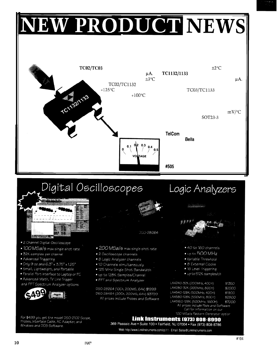
TEMPERATURE-TO-VOLTAGE CONVERTERS
TelCom has introduced a series of low-cost solid-state temperature sensors that provide a linearized output
voltage directly proportional to measured temperature. Applications include general-purpose temperature
measurement, power-supply thermal management, temperature monitors, and controls.
The
are precision-grade devices with a guaranteed accuracy of
at 25°C
and a typical supply current of 40
The
are consumer-grade devices
with a guaranteed accuracy of
at 25°C and a typical supply current of 60
The
have a temperature measurement range of -20°C to
and operate with a single supply. The
operate over
the -20°C to
range with an output voltage that is directly cali-
brated in degrees centigrade but requires an external pull-down resis-
tor to a negative voltage source for measurements below 0°C.
Each device has a voltage slope with temperature of 10
and is available in either a small TO-92 or
package.
Pricing ranges from $0.32 to $0.41 in quantity.
Semiconductor, Inc.
1300 Terra
Ave.
Mountain View, CA 94039-7267
(650) 968-9241
Fax: (650) 967-l 590
Issue 88 November 1997
Circuit Cellar
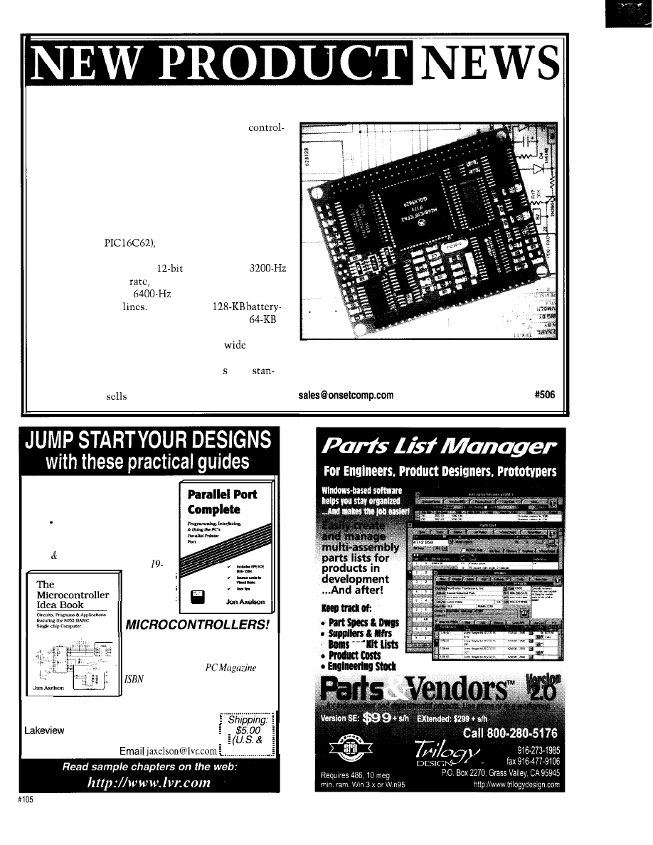
DATA LOGGER/CONTROLLER
The Tattletale Flash express data logger and
lcr engine has been introduced by Onset Computer
Corp. The TFX-11 integrates data-logging and control
hardware with TFBASIC software for data collection
and control in one product. Its small size, low power
requirements, and nonvolatile flash EEPROM make it
ideal for embedded portable or remote data-logging and
control applications.
The TFX- 11 includes dual processors (Motorola ‘HC 11
and Microchip
512
KB of nonvolatile flash
memory, a hardware battery-backed real-time clock, 11
analog input channels with
resolution and
maximum sampling
eight analog input channels
with S-bit resolution,
maximum sampling rate,
and 16 digital I/O
It also features
backed RAM, configured as 64-KB program and
data storage, and an RS-232 hardware UART.
The 2.4” x 3.2” x 0.5” TFX- 11 accepts a
range of
power-supply voltages from 6 to 30 VDC. Data can be
offloaded from flash memory in under 30 via a
dard PC parallel port.
The TFX- 11
for $295.
Onset Computer Corp.
P.O. Box 3450
l
Pocasset, MA 02559-3450
(508) 563-9000
l
Fax: (508) 563-9477
l
www.onsetcomp.com
NEW!
“A focused book that
delivers what it promises: detailed
technical information on the parallel
port.” Windows Developer’s Journal
“It’s been a while since I’ve seen a
book as practical as this one.”
-Nuts Volts
ISBN o-96508
I-5
$39.95
343
pages
Includes
disk
“An ideal introduction to low-end
embedded design.” EDN
“The writing is a model of clarity
and conciseness.“-
0-9650819-O-7
273
pages. $31.95
Order line: I-800-247-6553
For more information or international orders:
Research Phone 608-241-5824
2209 Winnebago St. Fax
6 0 8 - 2 4 1 - 5 8 4 8
Madison, WI 53704
Canada)
l
and
Circuit Cellar INK”
Issue 88 November 1997
11
FEATURES
Fuzzy Logic in Automotive
Engineering
Self-Evolving Systems and
Liability
Fuzzy Concepts Using C
Constantin von Altrock
Fuzzy Logic in
Automotive Enaineerina
uzzy logic is a
powerful way to put
engineering expertise
into products in a short
amount of time. It’s highly beneficial
in automotive engineering, where
many system designs involve the expe-
rience of design engineers as well as
test drivers.
Over the past years, fuzzy logic has
become is a common design technology
in Japan, Korea, Germany, Sweden,
and France. The reasons are manifold.
First, control systems in cars are
complex and involve multiple param-
eters.
Second, the optimization of most
systems is based on engineering exper-
tise rather than mathematical models.
“Good handling, “Fahrvergniigen,” and
“riding comfort” are optimization goals
that can’t be defined mathematically.
Third, automotive engineering is
competitive on an international scale.
A technology that proves a competi-
tive advantage is soon commonly used.
In this article, I point to case stud-
ies in
braking systems (ABS),
engine control, and automatic gearbox
control. show how superior perfor-
mance is achieved via fuzzy-logic and
neural-fuzzy design techniques. I also
discuss development methodologies,
tools, and code speed/size require-
ments.
12
88
November 1997
Circuit Cellar
ABS WITH FUZZY LOGIC
In 1947, Boeing developed the first
ABS for airplanes as a mechanical
system. Today, ABS is standard equip-
ment on most cars. A microcontroller
and electronic sensors measure the
speed of every wheel and control the
fluid pressure for the brake cylinders.
Mathematical models for a car’s
braking system exist, but the interaction
of the braking system with the road is
far too complex to model adequately.
Hence, today’s ABS contains the engi-
neering experience of years of testing
in different roads and climates.
PRODUCING FUZZY ABS
Because fuzzy logic is an efficient
way to put engineering knowledge into
a technical solution, it’s no surprise
that many ABS applications are already
on the market. Currently, Nissan and
Mitsubishi ship cars with fuzzy ABS.
Honda, Mazda, Hyundai, BMW, Bosch,
Mercedes-Benz, and Peugeot are work-
ing on solutions as well.
ABS also benefits from fuzzy logic’s
high computational efficiency. During
a control loop time of 2-S ms, the con-
trollers must fetch all sensor data, pre-
process it, compute the ABS algorithm,
drive the bypass valves, and conduct the
test routines. Any additional function
thus has to be computationally efficient.
Most ABS systems use 16-bit con-
trollers, which can compute a medium
size fuzzy-logic system in about 0.5 ms,
using only about
ROM space
You can check out a comparison of
computing times of fuzzy-logic systems
on different microcontrollers
BRAKING BASICS
There are different ways in
which fuzzy logic is used in
ABS design. The implementa-
tion of Nippondenso that I
present exhibits an intelligent
combination of conventional
techniques with fuzzy logic.
Let’s first discuss some
basics of the braking process. If
a wheel rotates exactly as fast
as it corresponds to the speed
of the car, the wheel has no
braking effect at all. If the
wheel doesn’t rotate at all, it is
blocked.
The blocking situation has two dis-
advantages. First, a car with blocking
wheels is hard to steer. Second, the
brake effect is not optimal. The point
of optimum brake effect is between
these two extremes.
The speed difference between the
car and the wheel during braking is
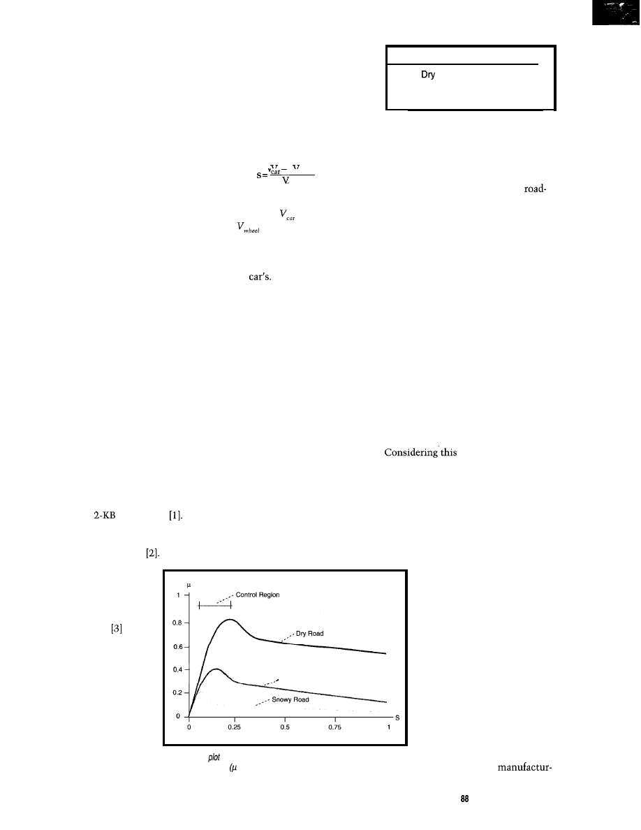
called “slack.” Its definition is:
“wheel
car
where s is slack (between 0 [no braking]
and 1 [blocking]),
is the car’s veloc-
ity, and
is the wheel’s velocity.
Figure 1 plots the relation between
brake effect and slack for different road
surfaces. For s = 0, the wheel’s speed
equals the
In the case of s =
1,
the
wheel blocks completely.
The curves show that the optimum
brake effect lies between these two
extremes. However, the point of maxi-
mum brake effect depends on the type
of road. Table 1 lists typical values.
ROAD SURFACE
Conventional ABS controls the
bypass valves of the brake fluid so the
slack equals a set value. Most manu-
facturers program this set value to a
slack of 0.1, which is a good compro-
mise for all road conditions.
But, as Figure 1 and Table 1 show,
this set value is not optimal for every
road type. By knowing the road type, the
braking effect can be enhanced further.
So, how do you determine what the
road type is? Asking the driver to push
a button on the dashboard before an
emergency brake is not feasible.
Road Condition Optimum Slack (s)
0.2
Slippery or Wet
0.12
Ice or Snow
0.05
Table l--The slack value for maximum brake effect
depends on the road condition.
Wet Road
The fuzzy-logic system then evalu-
ates the reaction of the car to the brak-
ing and estimates current road surface.
estimate, the ABS
corrects the set value for the slack to
achieve the best braking effect in the
interval from s = 0.05 to s = 0.2.
The fuzzy-logic system only uses
input data stemming from the existing
sensors of the ABS. Such input variables
are deceleration and speed of the car,
deceleration and speed of the wheels,
and hydraulic pressure of the
brake fluid. These variables
indirectly indicate the current
operation point of the braking
and its behavior over time.
Experiments show that a
first prototype with just six
fuzzy-logic rules improves per-
formance significantly. On a
test track alternating from
snowy to wet roads, the fuzzy
ABS detected the road-surface
changes even during braking.
Sensors provide one logical alterna-
tive. Many companies have evaluated
different types of sensors and concluded
that sensors which deliver good
surface identification are too expensive
or not sufficiently robust.
However, consider sitting in a ‘car
equipped with a standard ABS. After
driving at a known speed, you could jam
on the brake so the ABS starts to work.
Even if you didn’t know what the
road surface was like, you could make
a good guess from the car’s reaction. If
a driver can estimate the road surface
from the car’s reaction, fuzzy logic can
implement the same ideas into the ABS.
Nippondenso did exactly this. When
the ABS first detects the wheel block-
ing, it starts to control the brake-fluid
valves so each wheel rotates with a
slack of 0.1.
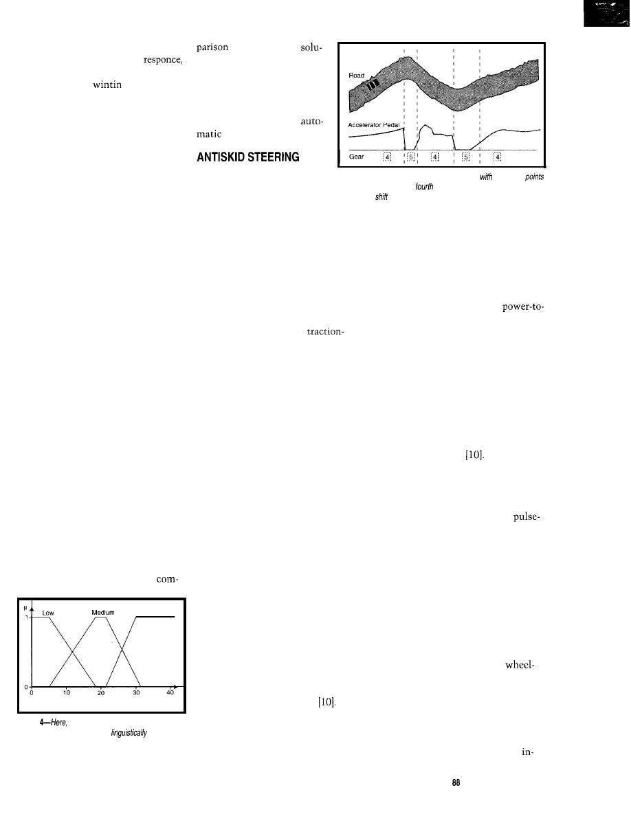
Figure l--This
illustrates brake effect over the wheel slacks for dry, wet, and
snowy road surfaces. is the friction coefficient or measure of brake effect)
A FUZZY BRAKE?
Due to the high competition
in this area, most
Circuit Cellar INK@
Issue November 1997
13
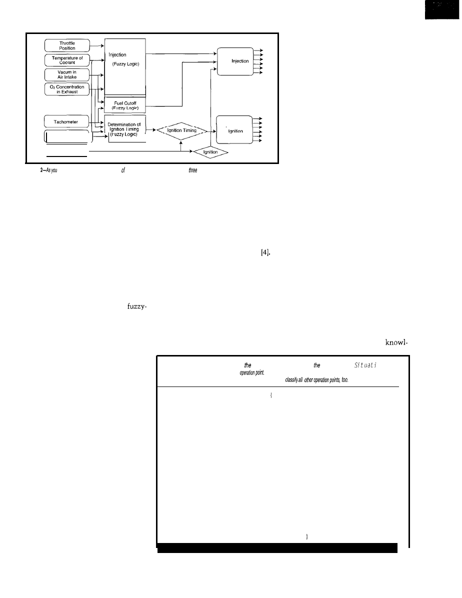
Determination of
Amount
Fuel
Electronic
K n o c k S e n s o r
Angle of
Crankshaft
Figure
can see,
the engine controller NOK Corporation contains
fuzzy-logic modules.
ers are reluctant to publish any details
about the technologies they use. The
cited application only shows results
from an experimental fuzzy-logic sys-
tem. The details about the final prod-
uct aren’t published.
Also, some car makers (especially in
the U.S.) worry about the negative con-
notation of the word “fuzzy.” Since it
implies imprecision and inexactness,
manufacturers are afraid that drivers
may think a fuzzy ABS is inferior.
Others are threatened by the possibil-
ity of a suit in which a clever lawyer
suggests to a layman’s jury that a
logic ABS is something hazardous.
In Japan, where an appreciation for
ambiguity lies in the culture, “fuzzy”
doesn’t have a negative connotation. By
contrast, it’s an advantage, as it enables
intelligent systems. Hence, companies
are proud of its use and promote it in
their advertising.
In Germany, on the other hand, the
concepts of fuzziness and engineering
masterpiece do not fit together well in
the public perception. Hence, most
manufacturers using fuzzy logic in ABS
hide the fact. After all, a fuzzy-logic
system is only a segment of assembly
code in a microcontroller. Once imple-
mented, who can tell that this code
contains fuzzy logic!
VERIFICATION AND STABILITY
When many publications about fuzzy
logic appeared for the first time about
five years ago, even reputed scientists
and professors in the U.S. stated that
fuzzy logic shouldn’t be used for critical
applications. They claimed that it
produces inherently instable systems.
This attitude is truly shameful. They
demonstrated only that they did not
understand what fuzzy logic is about.
A fuzzy-logic system is a time invari-
ant, deterministic, and nonlinear sys-
tem-nothing fuzzy about that. Such
systems are already known and applied
in control engineering, and conventional
stability theory covers them well
In the case of a fuzzy ABS, stability
isn’t even an issue. Conventional ABS
was considered stable for any slack set
value in the interval from 0.05 to 0.2.
Hence, a fuzzy-logic road-surface esti-
mator that tunes this value to the opti-
mum cannot make the ABS instable.
Let’s move on to see how fuzzy logic
easily implements human experience
in an embedded engine-control system.
ENGINE CONTROL
The control of car and truck engines
is becoming increasingly more complex
with more stringent emission standards
and constant effort to gain higher fuel
efficiency. Twenty years ago, control
systems were mechanical (i.e., carbure-
tor, distributor, and breaker contact).
Now, microcontroller-based systems
control fuel injection and ignition.
Since the control strategy for an
engine depends strongly on the current
operating point (e.g., revolutions, mo-
mentum, etc.), linear control models,
(e.g., PID) are not suitable.
On the other hand, no mathematical
model describing the complete behav-
ior of an engine exists. Most engine
controllers use a look-up table to repre-
sent the control strategy. The table is
generated from the results of extensive
testing and engineer’s experience.
The generation of such a look-up
table, however, is only suitable for
three dimensions (two inputs and one
output). Also, the generation and inter-
pretation of such tables is difficult and
considered a black art.
Although fuzzy logic can replace
these look-up-tables, most manufactur-
ers will not publish any details on a
fuzzy-logic engine-control solution.
This secretiveness is due to the fact
that the rules of the fuzzy-logic system
make the entire engine-control
Listing l--The current operation point of engine is classified by linguistic variable
on.
Each linguistic term
denotes a typical
Because each term is represented as a fuzzy-logic
membership function, the linguistic variable can
linguistic variable Situation
Term 1: Start
Control strategy is that the cold engine runs smooth. Ignition is
timed early, and the mix is fat:
Term 2: Idle
Control ignition timing and fuel injection depending on engine
temperature to ensure that the engine runs smooth;
Term 3: Normal drive, low or medium load
Maximize fuel efficiency by meager mix, watch knocking;
Term 4: Normal drive, high load
Fat mix and early ignition to maximize performance. The only
constraint is the permitted emission maximum:
Term 5: Coasting
Fuel cut-off, depending on situation;
Term 6: Acceleration
Depending on load, fattening of the mix
1 4
Issue 88 November 1997
Circuit Cellar INK@
Photo 1 ---This model car
is used
in high-speed driving experiments.
edge of the company
completely transparent.
They are afraid competi-
tors will learn too much
about the solution by
disassembling the fuzzy-
logic rules.
IDENTIFY DRIVING CONDITION
Nok and Nissan’s case study gives
the benefits of fuzzy logic in engine
control. Figure 2 depicts the compo-
nents of this engine controller, which
contains three fuzzy-logic modules.
The system first notes the engine’s
operational condition by the linguistic
variable S i t a t
n.
This variable has
the linguistic terms in Listing
The determination of S i t a t i is
a state estimation of the operation
point. Because S
i t u
a t i on is a linguis-
tic variable, more than one term can
be valid at the same time, so combina-
tions of the operational points can be
expressed as defined by the terms.
A possible value of S i t a t i could
be (0.8; 0.3). Linguistically,
this value represents the driving condi-
tion “engine started a short while ago,
normal drive condition at medium or
low load, slightly accelerating.” From
this operation-point identification, the
individual fuzzy-logic modules control
injection, fuel cutoff, and ignition.
Like ABS, engine control needs a very
short loop time. Some systems are as
fast as 1 ms for an entire control loop.
Some manufacturers design the system
using fuzzy logic but then translate it
into a look-up table for faster processing.
Although a look-up table computes
faster, memory requirements may pro-
hibit its use. A look-up table with two
inputs and one output, all S-bit resolu-
tion, already requires 64 KB of ROM.
Restricting the resolution of the
input variables to 6 bits each, the look-
up-table still requires 4 KB. A table with
three inputs and one output, all inputs
resolution, requires MB.
Some engineers implemented a look-
up table with a limited resolution and
used an interpolation algorithm. How-
ever, the interpolation needs about as
much computing time as the fuzzy-
logic system itself
Another published application of
fuzzy logic in engine control is an idle
control unit by Ford Motor Corp.
Next, let’s check out
transmission control to show how
fuzzy-logic systems can adapt their
control strategy to drivers.
ADAPTIVE AUTOMATICS
When the first three-speed automatic
transmissions appeared on the market
about 30 years ago, the engine power of
most cars was just sufficient to keep
the car in pace with traffic. The neces-
sity of getting maximum momentum
from the engine determined the shift
points for the gears.
Now, when most car engines can
deliver much more power than neces-
sary to keep the car in pace with traffic,
automatic transmission systems have
up to five speeds, and fuel efficiency has
become an important issue, controlling
shift points is much more complex.
Five speeds and higher engine power
give the automatic-transmission system
a much higher degree of freedom. Driv-
ing at 35 MPH, a three-speed automatic
transmission has to select second gear.
A five-speed transmission with a pow-
erful engine can select second gear for
maximum acceleration, third gear for
normal driving condition, and fourth
gear for minimal acceleration.
ACCELERATE OR SAVE FUEL
Unfortunately, the goal for the con-
trol strategy is in a dilemma. For maxi-
mum fuel efficiency, you want to select
the next higher gear as early as possible.
(CONNECTS TO
AR-16 RELAY INTERFACE (16 channel) . . . . . . . . . . . . 69.96
Two 8 channel (TTL level)
outputs are
provided for
connection to relay cards or other devices (expandable
to 128
using EX-16 expansion cards). A variety of
relays car sand relays are stocked. Call for more info.
AR-2 RELAY INTERFACE (2 relays, 10
RD-6 REED RELAY CARD (6 relays, 10
49.95
RH-6 RELAY CARD (10 amp
277
A N A L O G
D I G I T A L
(CO
N
NECTS
RS-232)
ADC-16
CONVERTER’ (16
AD CONVERTER* (6 channel/IO
Input voltage, amperage, pressure. energy usage, light,
joysticks and a wide variety of other types of analog
signals.
available (lengths to 4,000’).
Call for info on other
configurations and 12 bit
converters (terminal block and cable sold separately).
Includes Data Acquisition software for Windows 95 or 3.1
TEMPERATURE INTERFACE’ (6
includes term. block 8 temp. sensors (-40’ to 146’ F).
STA-6 DIGITAL INTERFACE’ (6
99.95
Input on/off status of relays,
HVAC equipment.
security devices, keypads, and other devices.
PS-4
SELECTOR (4 channels
Converts an RS-232 port into 4 selectable RS-422 ports.
CO-422 (RS-232 to RS-422 converter) . . . . . . . . . . . . . . . . . . . $ 39.96
l
EXPANDABLE...expand your interface to control and
monitor up to 512 relays, up to 576 digital inputs, up
126
inputs or up to 128 temperature inputs
the PS-4,
X-16, ST-32 AD-16 expansion cards.
l
FULL TECHNICAL
over
telephone by our staff. Technical reference
including test software pro
GW Basic,
examples in
Basic.
Turbo C, Assembly and others are provided.
l
HIGH
for continuous 24
industrial applications
10 years of proven
performance in the energy management field.
l
CONNECTS TO RS-232, RS-422
with
IBM and compatibles, Mac and most computers. All
standard baud rates and protocols (50 to 19,200 baud).
FREE INFORMATION
our 800 number.
Fax E-mail to order, or visit our Internet on-line catalog.
Technical Support (614) 464-4470
Visa-Mastercard-American Express-COD
Internet E-mail:
International Domestic FAX: (614) 464-9666
for information, technical support 8 orders.
ELECTRONIC ENERGY CONTROL,
360 South Fifth Street, Suite 604
Columbus. Ohio 432155491
Circuit Cellar
Issue 88 November 1997
But for maximum performance, you
therefore proves to efficiently imple-
switch to the next higher gear later.
ment the technology.
If you have a standard shift, you
choose your strategy depending on the
traffic condition. An automatic gearbox
has no understanding of the traffic
condition or the driver’s wishes.
In 199 1, Nissan introduced fuzzy-
logic-controlled automatic five-speed
transmission systems 7, Honda
followed in 1992
and GM/Saturn in
1993.
However, intelligent control tech-
niques can enhance automatic trans-
missions as it is based on experience
and engineering knowledge rather than
mathematical models. Fuzzy logic
The job for the fuzzy-logic system
in these applications is similar:
l
avoid “nervous” shifting back and
forth on winding or hilly roads
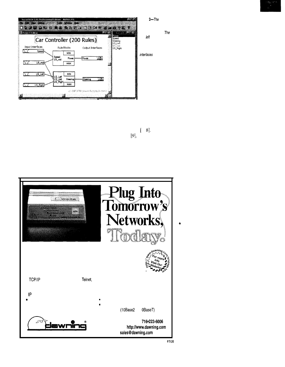
Photo
first
version
of fhe fuzzy-logic
controller has
200 rules
in two rule blocks.
four boxes indicate
input interfaces for
sensors, the two right
boxes indicate output
for the
actuators, and the two
large boxes in the
middle represent fuzzy-
logic rule blocks.
W
hy limit the intelligence of serial device connections to your
Ethernet network? The new Secure Network Interface from
Dawning can provide capabilities far beyond straight-in
connections or terminal servers at comparable prices. With the
SNI you can have the features of a mini-Web server at each device:
l
stack supports FTP, SMTP,
l
Allows remote access using standard Web
and HTTP protocols.
browser software.
l
Acts as a mini-Web server with a discrete
l
Encryption and authentication options
address.
provide security (pending).
Definable access and delivery rules control
Custom programming available.
interaction with multiple users and
User-programmable for any serial device.
hosts.
l
Price: $595.
or 1
Smart Connections
Call us at: l-800-332-0499
l
Fax:
716-223-8615
l
e-mail:
l
understand whether the driver wants
economical or sporty performance
l
avoid unnecessary overdrive, if switch-
ing to the next lower gear does not
deliver more acceleration
Figure 3 shows a typical situation
on a fast, winding road. With a standard
shift, you’d leave it in fourth gear, but
a five-speed automatic transmission
switches between the fourth and fifth
gears depending on the speed of the car.
The fuzzy-logic transmission con-
troller evaluates more than just the
current speed of the car. It also analyzes
how the driver accelerates and brakes.
To detect a winding road, the fuzzy-
logic controller looks at the number of
accelerator pedal changes within a
period. Figure 4 shows the definition of
the linguistic variable A
C
c e 1 e rat o r
p e d a l changes.
The
variance of the
accelerator pedal changes is input to
the fuzzy-logic controller.
Some of the rules estimating the
road and driving conditions from these
input variables are:
l
many pedal changes within a period
indicate a fast and winding road
l
few pedal changes within a period
indicate a freeway
l
many pedal changes within a period
and a high variance of pedal changes
indicate a slow and winding road
l
medium variance of pedal changes
indicates a fast and winding road
low variance of the pedal changes
indicates a freeway
The interesting part of this applica-
tion is that the fuzzy-logic controller
uses the driver as the sensor. It inter-
prets the driver’s reaction to the road
and driving conditions and adapts the
car’s performance accordingly.
This behavior could be used to define
an intelligent control system. The
technical system tries to understand
whether the human is satisfied with its
performance and adapts itself to suit
the needs of the human using it.
“INTELLIGENT” TRANSMISSIONS
Another example of an automatic
transmission system currently under
development in Germany illustrates
this possibility even better.
18
Issue 88 November 1997
Circuit Cellar INK@
If drivers want to accelerate, but
aren’t satisfied with their cars’
they unconsciously push the pedal
down even more
1-1.5s. This
scenario represents the subconscious
reaction of most drivers to unsatisfac-
tory acceleration.
The opposite case is similar. If the
automatic transmission detects that
the driver accelerates carefully and
takes the foot off the accelerator long
Most drivers don’t even realize that
before red lights, chances are that the
they like the car to accelerate faster. If
an automatic transmission system is
capable of detecting this, it can move
driver wants high fuel efficiency.
the shift points higher to achieve more
acceleration.
WHY FUZZY LOGIC?
The question remains, why do you
need fuzzy logic to implement these
intelligent functions? My answer:
while you can use other techniques to
implement these control strategies,
fuzzy logic is likely to be the most
efficient.
Intelligent control strategies are
built on experience and experiments
rather than from mathematical mod-
els. Hence, a linguistic formulation is
more efficient.
These strategies mostly involve a
large number of inputs. Most of the
inputs are only relevant for some spe-
cific condition. Using fuzzy logic,
these inputs are only considered in the
relevant rules, keeping even complex
control-system designs transparent.
Another consideration is that intel-
ligent control strategies implemented
in mass-market products have to be
implemented cost efficiently. In
High
Accelerator Pedal Changes Within a Period
Figure
driving condition is classified using a
linguistic variable. The variable
interprets
the amplitude of accelerator pedal changes within a
certain period.
to conventional
tions, fuzzy logic is often
much more computational
and code-space efficient.
Let’s look now at how
fuzzy logic enables the design
of new functionality for
steering control.
Active stability control
systems in cars have a long
history. First, ABS improved
Figure 3-A five-speed automatic transmission
fixed shift
a/ways switches between
and fifth gear on a winding road. A
driver with a
gearbox would leave it
in fourth gear.
braking performance by re-
ducing the amount of brake force ap-
plied by the driver to what the road
Second, traction-control systems,
surface can take. This system avoids
which do essentially the same thing as
ABS, improve acceleration. By reducing
skidding and sliding, resulting in shorter
engine power applied to the wheels to
what the road can take, a
braking distances.
control system maximizes acceleration
and minimizes tire wear.
After skid-controlled braking and
acceleration, the next logical step is
skid-controlled steering. An antiskid
steering system (ASS) reduces the steer-
ing angle applied by the driver through
the steering wheel to the amount the
road can take. It optimizes the steering
action and avoids sliding since a slid-
ing car is very difficult to restabilize,
especially for drivers not accustomed
to such situations.
Though an ASS makes a lot of sense
from a technical point of view, such a
system is harder to market. For an ABS,
you can prove that it never performs
worse than a traditional braking system.
For an ASS, this is hard to prove.
Also, it may be difficult to sell cars
that “take over the steering” in emer-
gency situations. Even ABS faced a
long period of rejection by customers
because they felt uneasy about a system
“inhibiting” their brake action.
For these reasons, it may take a long
time before ASS will be implemented in
a production car. All results shown in
this section stem from the research of
a German car manufacturer
Be-
cause this system is one of the most
complex fuzzy-logic embedded systems
ever developed, it effectively demon-
strates the potential of the technology.
THE TEST VEHICLE
Real experiments were made on a
modified Audi sedan and the 20” model
car shown in Photo 1. In the following
discussion, I only present the results
derived from the model-car experiments.
A midmounted I-hp electric motor
powers the car, rendering the
weight ratio of a race car. This setup
enables the researchers to perform
skidding and sliding experiments in
extreme situations at high speeds.
On dry surface, the car reaches a
velocity of 20 MPH in 3.5 s, with top
speeds up to 50 MPH. The speed for
most experiments ranges from 20 to
30 MPH. Each wheel features individual
suspension and has a separate shock
absorber. The car has disk brakes and a
lockable differential
The car’s controller uses the mother-
board of a notebook PC connected to
an interface board driving the actuators
and sensors. Actuators are power steer-
ing servo, disk brake servo, and
width modulated motor control.
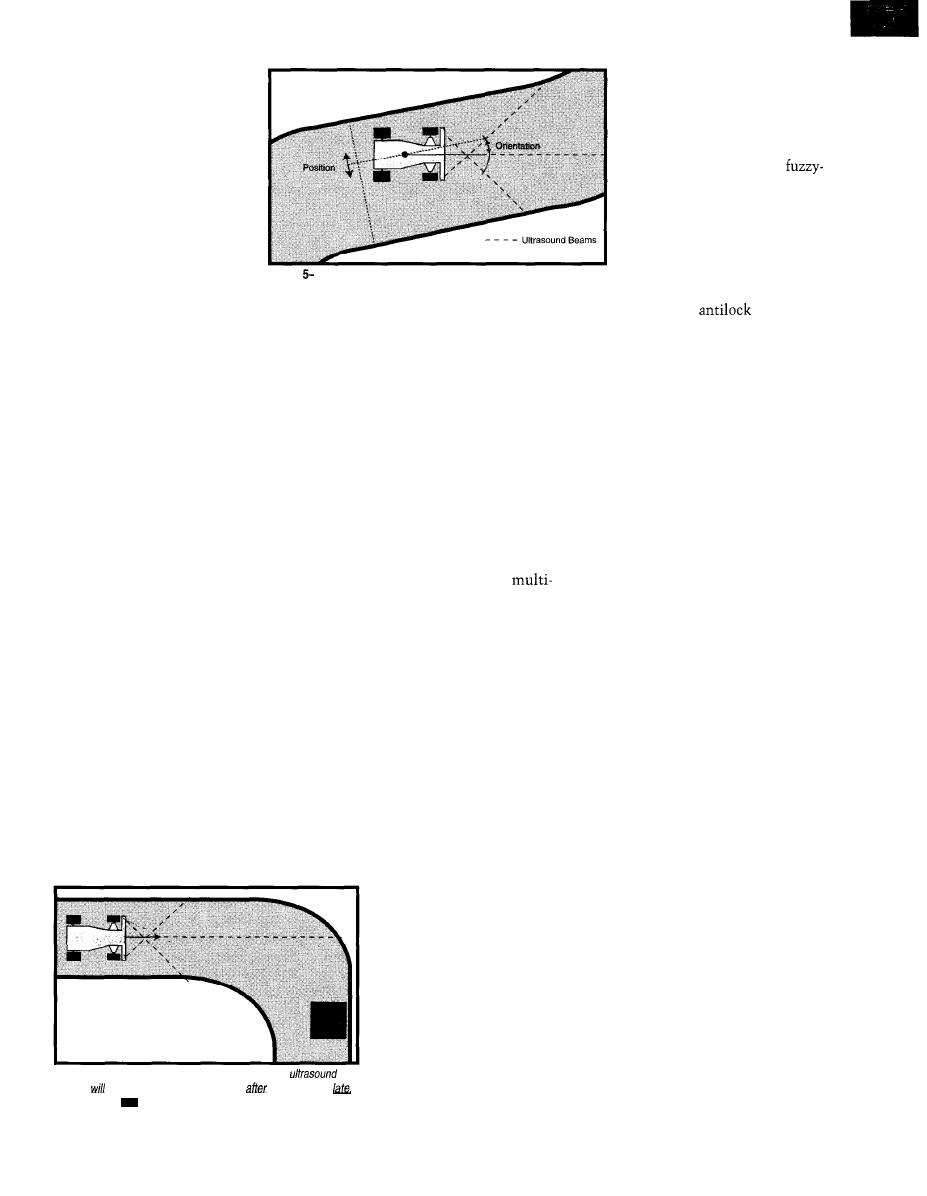
Sensors are three ultrasound (US)
distance sensors for tracking guidance
(see Figure 5) and infrared (IR) reflex
sensors in each wheel for speed. The
control loop time-from reading in
sensor signals to setting the values for
the actuators-is 10 ms.
To measure the dynamic state of
the car (e.g., skidding and sliding), IR
sensors measure the individual speed
of all four wheels. Evaluating
speed differences, the fuzzy-logic sys-
tem interprets the current situation.
Three fixed-mounted US sensors
measure the distance to the next ob-
stacle to the front, left, and right. This
setup permits autonomous operation
of the car. Low-cost sensors were
Circuit Cellar INK@
Issue November 1997
1 9
tentionally used in this
study-rather than CCD cam-
eras and image-recognition
techniques-to show that ex-
pensive sensors can be replaced
by a fuzzy-logic control strategy.
Figure 6 shows a sample
experiment involving the model
car. The obstacle is placed
right after the curve, so the US
sensors of the car detect the
obstacle too late.
Figure
To not hit the obstacle, the
car has to decide for a very rapid turn.
To optimize the steering effect, the
anti-skid controller must reduce the
desired steering angle to the maximum
the road can take, avoiding both slid-
ing and hitting the obstacle.
MODEL BASED VS. FUZZY LOGIC
In theory, you can build a mechanical
model for a car and derive a mathemati-
cal model with differential equations to
implement a model-based controller.
In reality, the complexity of this ap-
proach is overwhelming, and the result-
ing controller would be difficult to tune.
Here is the point for fuzzy logic:
race-car drivers can control a car in
extreme situations very well without
solving differential equations. Hence,
there must be an alternative way for
anti-skid steering control.
This alternative way is to represent
the driving strategy in engineering
heuristics. Although there are multiple
ways of expressing engineering heuris-
tics, fuzzy logic has proven very effec-
tive for the following reasons.
You can often formulate engineer-
ing heuristics in if-then causalities. In
contrast to other methods of express-
ing if-then causalities (e.g., expert
systems), the computation in a fuzzy-
-Three ultrasound sensors guide the car in the track.
logic system is quantitative rather
than symbolic.
In a fuzzy-logic system, you use a
few rules to express general situations,
and then the fuzzy-logic algorithm
deduces decisions for the real situations
that occur. A conventional expert
system needs a rule for each possible
situation.
In a fuzzy-logic system, every ele-
ment is self-explanatory. Linguistic
variables are close to the human repre-
sentation of continuous concepts. Fuzzy
if-then rules combine these concepts
much the same way humans do.
Fuzzy logic is nonlinear and
parametric by nature. So, it can better
cope with complex control problems
that are also nonlinear and involve
multiple parameters.
And finally, fuzzy logic can be effi-
ciently implemented in embedded
control applications. Even on a standard
microcontroller, a fuzzy-logic system
can outperform a comparable conven-
tional solution both by code size and
computing speed.
gure 6-/n this example of an experiment, the car’s
sensors detect the obstacle p/aced right
the curve very
making a rapid
necessary.
DESIGN AND IMPLEMENTATION
Photo 2 shows the first version of a
fuzzy-logic controller for the car. The
objective for this controller was autono-
mous guidance of the car in
the track at slow speed, where
no skidding and sliding yet
occurs.
In Photo 2, the lower rule
block uses the distances
measured by the three US
sensors to determine the
steering angle. The upper rule
block implements a simple
speed control by using the
distance to the next obstacle
measured by the front US
sensor and the speed of one
front wheel only.
Due to the slow speeds, no
skidding or sliding occurs. All
wheel speeds are the same.
This first version of the
logic controller contained about
200 rules and took only a few
hours to implement.
The second version of the
fuzzy-logic controller imple-
ments a more complex fuzzy
system for dynamic stability
control. It includes
braking as
well as traction and antiskid steering
control
(see
Photo 3).
This 600-rule fuzzy-logic controller
has two stages of the fuzzy inference.
The first stage, represented by the
three left rule blocks, estimates the
state variables of the car’s dynamic
situation from sensor data. The two
lower rule blocks estimate skidding
and sliding states from speed sensor
signals, while the upper rule block
estimates the car’s position and orien-
tation in the test track.
Note that the output of the left three
rule blocks-the state variable estima-
tion-is linguistic rather than numeri-
cal. An estimated state of the car can
therefore be “the position is rather left,
while the orientation is strongly to the
right, and the car skids over the left
front wheel.”
The second stage, represented by
the three right rule blocks, uses these
estimations as inputs to determine the
best control action for that driving
situation. The upper rule block deter-
mines the steering angle, the middle
one the engine power to be applied,
and the lower one the brake force.
Such a two-stage control strategy is
similar to the human behavior. It first
analyzes the situation and then deter-
mines the action. It also allows for
efficient optimization, since the total
of 600 rule structures in six rule blocks
can be designed and optimized inde-
pendently.
The first version of the controller
was only able to guide the car on au-
tonomous cruise (see Photo 2). The
second version also succeeded to dy-
namically stabilize the car’s cruise via
ABS, traction control, and ASS
(see
Photo 3).
20
Issue 88
November 1997
Circuit Cellar INK@
However, this version
required a much longer de-
sign time before the results
were completely satisfactory.
The second version also uses
advanced fuzzy-logic tech-
nologies such as FAM infer-
ence
1
and the Gamma
aggregational operator
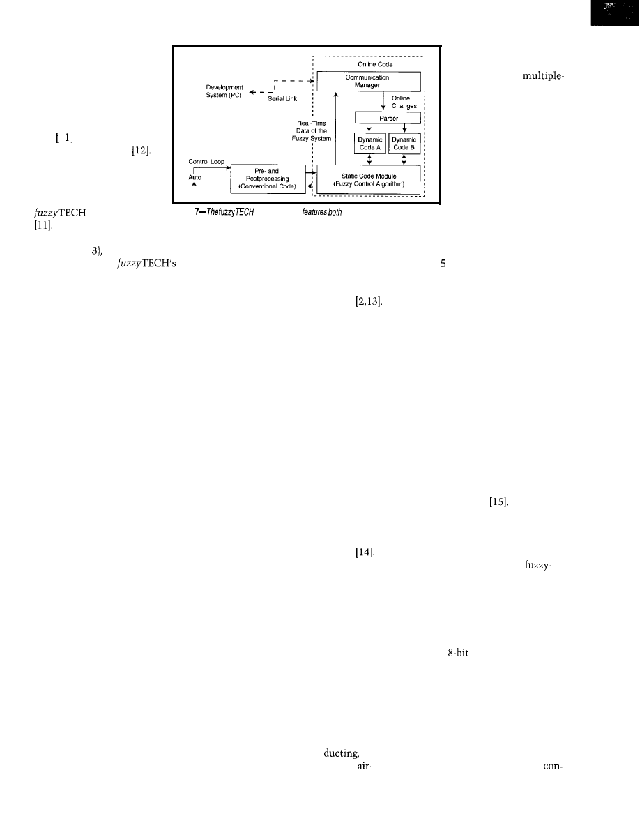
ONLINE DEVELOPMENT
The development of the
fuzzy-logic system used the
software product
Figure
Online Edition
visualization of running system
Given the graphical
and modifications on-the-fly.
Photo 4 shows the
control surface of a part of
a HVAC system-the
blower-speed control.
Blower speed depends on
two input variables-the
temperature error (i.e., the
definition of the system structure (cf.
Photos 2 and the linguistic variables,
and the rule bases,
com-
piler generates the system as C or
assembly code.
verification were expedited due to the
controller’s transparency. And, the poor
computational performance of early
fuzzy-logic software solutions was
overcome via a new generation of
software-implementation tools
in-car temperatur’e minus
the set-point temperature) and the
engine-coolant temperature.
This code was implemented on a
PC board mounted on the car. Figure 7
shows how the running fuzzy-logic
system was modified on-the-fly for
optimization.
The fuzzy-logic code is separated
into two segments. One contains all
static parts-code that doesn’t need to
be modified for system alterations. The
other segment contains all dynamic
parts-the code containing member-
ship functions of the linguistic variables,
the inference structure, and the rules.
The dynamic segment is doubled,
with only one of the segments active
at the same time. In this situation, the
parser, linked to the development PC
via a communications manager, can
modify the inactive code segment.
This technique enables modifica-
tions on the running system without
halting or compiling. At the same time,
the entire inference flow inside the
fuzzy-logic controller is graphically
visualized on the PC, since the com-
munications manager also transfers all
real-time data.
The ASS example demonstrates the
applicability of fuzzy-logic technologies
for a complex control problem found
in the automotive industry. The system
was a straightforward design based on
experimental experience without a
mathematical model of the process.
During optimization, the control
strategy was easy to optimize due to
the linguistic representation inherent
in the fuzzy-logic system. Tests and
flow, and the ratio of fresh
to recirculated air. This
multiple-input,
output control problem
doesn’t fall into any con-
venient category of tradi-
tional control theory.
In the remainder of this article, I
provide an overview of other automo-
tive applications where fuzzy logic has
been used successfully.
HVAC IN CARS
Fuzzy-logic design technologies are
well-established in heating and air
conditioning of residences and offices.
Hence, it’s no surprise that many car
manufacturers also use fuzzy logic in
their HVAC-system designs.
While most car manufacturers work
on these systems, very few publish
their efforts. The control approach in
general and hence the use of fuzzy
logic in the design differ significantly
for each manufacturer. In this section,
I use an example that Ford Motor
Company developed in the U.S.
The fundamental goal of HVAC in
cars is to make vehicle occupants
comfortable. Human comfort, however,
is a complex reaction, involving physi-
cal, biological, and psychological re-
sponses to the given conditions. The
performance criterion-comfort-is not
some well-defined mathematical for-
mula but a sometimes inconsistent
and empirically determined goal.
Typical HVAC-system sensors
measure cabin temperature, ambient
temperature, sun heating load, humid-
ity, and other factors. Typical actuators
are variable speed blowers, means for
varying air temperature,
and
doors to control the direction of
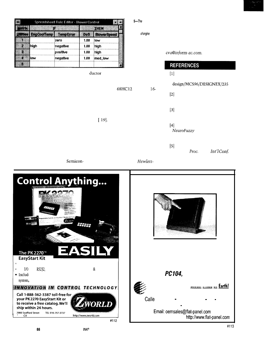
Photo shows the rule base. If the
temperature error is zero, low blower
speed is desired. If its too hot inside (i.e.,
positive temperature error), high blower
speed is needed to cool the cabin.
If the error is negative, indicating
that it’s too cold inside, and the engine
is cold, little blower speed is needed
for defrost. If the error is negative but
the engine is warm, high blower speed
is needed to heat up the cabin.
OTHER APPLICATIONS
This section briefly introduces
some other examples of fuzzy-logic
control in automotive engineering. For
details, refer to the papers cited.
Peugeot Citroen of France devel-
oped a fuzzy-logic system for an intel-
ligent cruise control
The system
combines multiple functions for au-
tonomous intelligent cruise control
(i.e., following another vehicle, stop
and go procedures, and emergency
stop]. The system uses three
logic blocks with four inputs, one
output, and 30 rules each.
Optimization and verification of the
rule base used a Citroen XM sedan
with automatic gearbox and ABS as
test vehicle. The fuzzy-logic controller
runs on an
microcontroller.
The car uses a speed sensor and a
single-beam telemeter for the distance
to the next car. The actuators com-
mand brake pressure and accelerator.
Tests show the fuzzy-logic controller
can handle the cruise under all the
tested conditions.
Future regulations in the European
Community (EC) require a speed
22
Issue 88
November 1997
Circuit Cellar INK@
Data Acquisition
new Value-line has
uncompromising design features
and high quality components at
prices below the low cost guys!
Just check out the specs:
5500MF
8 channels
A/D,
16 digital I/O, Counter/Timer
H i g h S p e e d
8 channels
A/b,
DMA
M u l t i - F u n c t i o n D M A
5516DMA
16 channels 12-bit A/D,
DMA, 16 digital
H i g h R e s o l u t i o n
5500HR
16 channels
A/D,
DMA, 8 digital
learn more:
voice
800-648-6589
fax
web
American Data Acquisition Corporation
70 Tower Office
Park,
MA 01801
USA
(Car Controller (600 Rules)]
Input
Interfaces
Rule Blocks
Interfaces
Photo
second version of fuzzy-logic controller.
controller uses advanced fuzzy-logic design
technologies and
a
of 600 rules.
trol for limiting truck speeds on roads
in Europe. Today’s speed limiters use
adaptive ND-type controller. However,
the resulting truck behavior is unsatis-
factory, compared to an experienced
driver.
Therefore, a number of recent de-
signs use fuzzy-logic control to achieve
robust performance, even under the
strong load changes of commercial
trucks
16,
A paper from Ford Electronics de-
scribes the design of a traction-control
system for a radio-controlled model car
The fact that Ford publishes
car applications is symptomatic of the
fear of many automotive manufactur-
ers to admit that they use fuzzy logic
as a design technique for “real” cars.
THE FUTURE IS FUZZY
Over the past five years, fuzzy logic
has significantly influenced the design
of automotive control systems. Since
using fuzzy logic involves a paradigm
shift in the design of a control system,
five years is a short period. The move
from analog to digital solutions has
taken a much longer time.
The key reason for fuzzy logic’s suc-
cess in automotive engineering lies in
the implications of its paradigm shift.
Previously, engineers spent much time
creating mathematical models of me-
chanical systems. More time went to
real-world road tests that tuned the
fudge factors of the control algorithms.
If they succeeded, they ended up
with a control algorithm of
Photo
graph depicts control surface of
air conditioner’s blower-speed control. Blower speed is
determined by temperature error and engine-coolant temperature.
24
Issue November 1997
Circuit Cellar
cal formulas involving many experi-
mental parameters. Modifying or later
optimizing such a solution is very diffi-
cult because of its lack of transparency.
Fuzzy logic makes this design process
faster, easier, and more transparent. It
can implement control strategies using
elements of everyday language. Every-
one familiar with the control problem
can read the fuzzy rules and understand
what the system is doing and why.
It also works for control systems
with many control parameters. Design-
ers can build innovative control sys-
tems that would have been intractable
using traditional design techniques.
The future for fuzzy logic in auto-
motive engineering is bright.
Photo
rule base
for
blower-speed control
shows how the two
variables
temperature and tempera-
ture error affect blower
speed.
manufacturers are incorporat-
ing fuzzy-logic instruction sets in
their controllers. Motorola just intro-
duced the new
family of
bit micros that integrate a complete
instruction set for fuzzy logic at no
extra cost.
Another new development is the
upcoming IEC
113 l-7
fuzzy-logic stan-
dard
This international standard
defines consistent fuzzy-logic develop-
ment and documentation procedures.
With these two developments, de-
signing with fuzzy logic becomes a
much simpler task.
q
Constantin
von Altrock began re-
search on fuzzy logic with
Packard in 1984. In 1989, he founded
and still manages the Fuzzy Tech-
nologies Division of Inform Software
Corp., a market leader in fuzzy-logic
development tools and turn-key appli-
cations You may reach Constantin at
Intel, “Fuzzy Anti-Lock Braking
System,” developer.intel.com/
1.
htm, 1996.
“Benchmark Suites for Fuzzy
Logic,” www.fuzzytech.com/
e_dwnld.htm, 1997.
N. Matsumoto et al., “Expert
antiskid system,”
IEEE IECON’87,
810-816, 1987.
C.
von Altrock,
Fuzzy Logic and
Applications Ex-
plained,
Prentice Hall, Englewood
Cliffs, NJ, 1995.
H. Kawai et al., “Engine control
system,”
of the
on
Fuzzy Logic and Neural Networks,
Iizuka, Japan, 929-937, 1990.
l
The fastest, easiest way to develop control systems
l
30
lines,
RS485, rugged enclosure,
LCD,
keypad
es all necessary hardware, simplified software development
step-by-step documentation and many sample programs.
Davis
95616 USA
FAX 916-753-5141
26
Issue
November 1997
Circuit Cellar
Touch The Future
LCD Touch Monitors
L C D T o u c h S c r e e n s
V G A L C D D i s p l a y s
LCD Controllers
ISA,
Analog, Video
E A R T H
lowest Prices on
Computer
Technologies
1110
Cordillera San Clemente CA 92673
Ph: 714-361-2333 Fax: 714-361-2121
FREE CATALOG available at
L. Feldkamp and G. Puskorius,
“Trainable fuzzy and neural-fuzzy
systems for idle-speed control,”
2nd IEEE Int’l. Conf. on Fuzzy
Systems, 45-51, 1993.
H. Takahashi, K. Ikeura, and T.
“5-speed automatic
transmission installed fuzzy reason-
ing,”
Engineering
toward Human Friendly Systems,
1136-1137, 1991.
H. Ikeda et al., “An intelligent
automatic transmission control
using a one-chip fuzzy inference
engine,
of the
Fuzzy
Systems and Intelligent Control
Conf. in Louisville, 44-50, 1992.
P. Sakaguchi et al., “Application
of fuzzy logic to shift scheduling
method for automatic transmis-
sion,” 2nd IEEE Int’l.
on
Fuzzy Systems, 52-58, 1993.
C. von Altrock, B. Krause, and
H.-J. Zimmermann, “Advanced
fuzzy logic control of a model car
in extreme situations,” Fuzzy Sets
and Systems,
41-52, 1992.
1 INFORM GmbH/Inform Soft-
ware Corp.,
and
Module 5.0 User’s
Manual, Chicago, IL, 1997.
H.-J. Zimmermann and U. Thole,
“On the suitability of minimum
and product operators for the inter-
section of fuzzy sets,” Fuzzy Sets
and Systems, 2,
173-186, 1979.
C. von Altrock and B. Krause,
“On-Line-Development Tools for
Fuzzy Knowledge-Base Systems of
Higher Order,” 2nd Int’l Conf. on
Fuzzy Logic and Neural Networks
Proceedings, Iizuka, Japan, 1992.
L.I. Davis et al., “Fuzzy Logic
for Vehicle Climate Control,” 3rd
IEEE Int’l.
on Fuzzy Sys-
tems, 530-534, 1994.
J.-P. Aurrand-Lions, M. des Saint
Blancard, and P. Jarri, “Autonomous
Intelligent Cruise Control with
Fuzzy Logic,” E
st Eur.
Congress on Fuzzy and Intelligent
Technologies, Aachen, l-7, 1993.
V.M. Thurm, P. Schaefer, and
W. Schielen, “Fuzzy Control of a
Speed Limiter,” ISATA Conf., 1993.
www.fuzzytech.com/e_a_spe.htm.
[ R. Russ, “Designing a Fuzzy
Logic Traction Control System,”
of the Embedded Systems
Conf., 2, 183-196, 1994.
www.fuzzytech.com/e_iec.htm.
Development System
Inform Software Corp.
200 1 Midwest Rd.
Oak Brook, IL 60523
(630) 268-7550
Fax: (630) 268-7554
www.fuzzytech.com
Fuzzy-logic
microcontroller
Motorola MCU Information
P.O. Box 13026
Austin, TX 78711
(512) 328-2268, x985
www.mcu.motsps.com
www.fuzzytech.com/motorola.htm
401
Very Useful
402 Moderately Useful
403 Not Useful
Introducing RI
and READS1 66
High Performance
Industrial Controller
Industrial Boards with GND VCC planes
Comes with C and Assembly Demos and FLASH programming software
READS166
an Integrated Visual Development Environment.
Smart Hardware Software Integration
Assembler, C Compiler, and Monitor
Native
Code to run on Windows95 and
Sophisticated Project Management System
Drag-and-Drop Code Development Libraries
l
Hardware-Aware Dynamic Debugging: Single Step, Breakpoints, Animation
Supports interrupts, Mixed Mode Programming (C
-- $167, READS1 66 Lite -- $300
Corporation
PO Box 90040, Gainesville, FL 32607
Tel: 352-373-4629, FAX 352-373-l 786
Download fully functional READS166 Demo
1509
Manor View
Road
l
Davidsonville, MD 21035
(410) 798-4038
voice,
(410) 798-4308 fax
e-mail:
l
home page:
Circuit Cellar INK@
Issue 88 November 1997
2 7
Self-Evolving
Systems
and Liability
Rod Taber
Who’s
for a System’s
Growing
tems shouldn’t be in
critical applications. Does
it make sense to sell a heart pacemaker
that places itself beyond testing? Should
the FDA approve such a system? Does
it deserve a patent? What legal problems
arise for the manufacturer if it fails?
Quick answers to such questions are
beyond the scope of a short article. Even
the legal system yields multiple con-
flicting opinions as it adjusts to new
technology and aligns itself with the
ever-changing social milieu. Neverthe-
less, in this article, I want to highlight
some issues for further discussion.
The 1980s brought us small, fast, and
cheap computers. We developed new
sensors and estimation theory. Neural
nets and fuzzy controllers are now in
video cameras, car transmissions,
elevators, and a host of other smart
consumer products. We progressed from
no adaptation to offline and online
adaptation.
The next step, self-evolving systems,
will produce very smart
machines that reconfigure themselves
depending on incoming data.
evolution goes beyond customary
adaptation. It entails paradigm shifts.
An example from pattern recognition
illustrates the idea. Incoming data
forces a machine to shift from a Gaus-
sian classifier to one based on some
other alpha stable distribution. In
doing so, it must forsake using the
arithmetic mean of pixel regions as a
measure of central tendency.
The mean and higher order moments
of the induced distribution may not
exist, as in the
distribution.
The machine may have to invent as it
goes along because the characteristic
exponent of the distribution curve
changes with time.
In a different context, a system may
switch from using one credit-reporting
agency to another, depending on real-
time transaction costs and accuracy. Or,
a pacemaker shifts from a constant to
a variable rate voltage spike to counter
impending arrhythmia.
All of this sounds a bit scary. Do we
really want machines with a high
degree of nondeterminism in special
applications?
Should machines evolve? Evolution
has been regarded as a fact of life since
Spencer first spoke of the survival of
the fittest. While the context was
biology over long-time scales, adapta-
tion plays an equivalent role in systems
and cybernetics.
Old-line’computer companies fall by
the wayside as more agile companies
offer new ideas and approaches. We
know that smart machines are here to
stay and that machine IQ will likely
increase. It’s a matter of competition
for market share and visibility.
Also, our legal system will neces-
sarily twist, resist, and adapt as it has
in the past. Witness the sea change in
public opinion on the tobacco issue.
Twenty years ago, a reasonable
person would accept that in taxing the
product, states in effect legalized and
legitimized tobacco use. States became
partners with the tobacco industry,
subsidizing it and helping farmers grow
tobacco for a slice of the pie.
Now, the states see a potential
source of unearned income. They argue
for an even larger slice, based on revi-
sionist history that has something to do
with the tobacco companies acting in
concert with cartoon camels to deceive
the public.
28
Issue 88
November 1997
Circuit Cellar INK@
My point is that, right or wrong,
perspectives change with time and
information. What can we learn or
infer from the tobacco problem? We
need to watch out for:
l
retroactive governmental disapproval
for devices
l
new liability for old devices
l
people who sue when they identify a
plausible target for litigation
What threats loom on the horizon
for computing as more and more de-
vices are able to evolve? Surely, the
usual dangers of personal-injury suits,
detrimental-reliance suits, and patent
litigation won’t disappear.
social-security crises will almost surely
wear down state treasuries and create
financial hardships.
Hence, governments and individuals
will look for easy litigation targets.
that environment, it’s going to be easy
to blame computers and smart devices
for problems real and imagined.
Is a self-evolving system inherently
riskier than a dumb system that refuses
to change even in the face of over-
whelming evidence? The legal question
is whether an increase in untrust-
worthiness translates into enhanced
legal liability and litigation probability.
Conversely, does an increase in
trustworthiness decrease liability?
Before engaging those questions, let
CONVENTIONAL COMPUTING
Most historians credit Von Neumann
with creating the foundations for digital
computing. His ideas ranged from
cellular automata to making reliable
systems out of unreliable components.
Digital computers soon found their way
from the War Department to the Cen-
sus Bureau and on to the general
processing departments of corporate
America.
These so-called Von Neumann com-
puters downsized odd years ago
through brand names like IMSAI,
TAIR, Processor Technology, and South-
west Technical Products. These small
computers held their position until the
mid 1980s when computers surfaced as
And, the future may bring strange
me make a few observations about
cultural values and severe financial
conventional computing and the
crunches. The federal pension and
rent legal system.
PCs and Macintoshes.
Years ago, technicians repaired
vacuum-tube computers on a
Patents
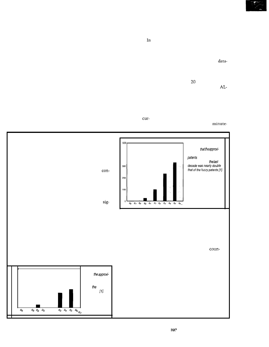
Moore’s law states that technology improves by a
Figure ii-/n this graph,
factor of two every 18 months. Chip densities double as
do internal computer clock rates, but new algorithms
come along only once in a while. Consumer products
and their patents shows an interesting fact-virtually
all smart machines use a version of the Mamdani
troller. Thus, there are several thousand products and
patents based on a single variety of model-free estimator.
The same can be said for neural networks but with a
little less force. The practical implication for fuzzy and
neural engineers is that the projects they’re working on
may be already patented. Figures i and ii show the
400
you see
mate number of neural
issued by the U.S.
Patent Office for
nificant increase in the number of fuzzy and neural
patents over the last decade. But, how many engineers
actually read patent summaries?
Small companies can’t afford a patent dispute, but
they may be forced into defending themselves-and
patent cases aren’t cheap. It may take a million dollars
just to get to first base. Not only do you pay for several
law firms working perhaps full time for more than a
year, but you have travel expenses, court reporters,
expert witnesses, and a whole realm of problems you
just don’t want to deal with. On top of that, a case may
300
Figure i--This graph
displays
mate number of fuzzy
200
patents issued per
year by U.S.
Patent Office
100
4
tie up senior engineering staff for more than a year. Your
competitors flourish, and you languish. In a real sense,
even if you win, you lose. It sounds bleak, and it is.
Large companies have full-time legal counsel and
several law firms on retainer. What can a small company
do? Well, forewarned is forearmed. The U.S. Patent Office
established more than 70 depositories around the
try. Large libraries subscribe to CD-ROM editions of
patents granted, and the library staff can help answer
your “how do I” questions quickly and at no cost.
Printed patents do cost a little, but you can often view
them on microfilm for free. Also, patent information is
available on the Web. You can sit at your computer and
search all patents from dozens of years ago to present day.
In the U.S., no one has easy access to patent applications
prior to a patent being granted. This situation may change
if special interests in Congress have their way. Last but
0
I.
not least, retain a patent search firm or patent attorney.
4
4 4
It’s
a lot cheaper than going to court.
Circuit Cellar
Issue 88 November 1997
29
to-minute schedule. Tubes replaced in
the morning literally burned out by the
afternoon.
The situation wasn’t much better
with early dynamic and static
for
the Intel 8080 and Motorola 6800 ma-
chines. Every techie from that era
remembers spending a huge amount of
time writing memory checkers. We
wrote programs to tell us the row and
column address of bad
chips on
boards. We used a lot of chips.
Now, desktop computers are much
more complex than the mainframes of
yesteryear in most respects, and they’re
much more reliable. In this case, com-
plexity correlates with reliability.
Software has also changed since the
days of the vacuum tube. We wrote
modifying code. Programmers loved its
on-the-fly nature.
But, software engineers labeled it a
hazard and a liability. It was difficult to
maintain, and the code depended on the
sequence of data inputs and a lot of
other stuff, none of which was neces-
sarily deterministic. Electrical engineers
therefore designed separate data and
instruction spaces to prevent it or at
least minimize its use.
No one seems to track the preva-
lence of self-modifying code anymore.
It isn’t an issue. Theoretical computer
scientists still wrestle with the prov-
ability of even static code. We have
existence theorems on computability,
but we can’t prove that a particular
program works as intended. Every
program is correct for some problem,
although it may incorrect for the prob-
lem at hand.
We can show by example that many
“real” programs are not correct for all
inputs. This is especially true for artifi-
cial intelligence in all its forms.
Pattern classifiers always fail, given
enough noise in the signal. We know
these devices will fail for some data
inputs. Such programs satisfice specifi-
cations. In other words, they do not
always satisfy those specifications but
rather reach a reasonable compromise.
Today, we simulate fuzzy systems,
neural networks, and genetic algorithms
in ways typically described as
ithmic. The new function approximators
and state search techniques are
free because the mapping from system
inputs to system outputs doesn’t use a
math model of the plant. Sanity check-
ers may supervise model references, but
the computing system doesn’t depend
on a mathematical model of the process.
Model-free estimators are clever end
runs around classical model techniques
like the Kalman filter. There are no
differential equations to solve. The
physical systems of interest either can’t
be expressed as differential equations
or, if such equations exist, they’re
beyond solution.
In a patent trial, how
do you explain Fourier
to an
uneducated jury!
. . .
Fuzzy model-free estimators such as
the Mamdani controller calculate the
expected value of a parameter given the
input data and fuzzy sets. Neural nets
of the popular feed-forward variety
suffer from the problem of
tionist glop.”
Given inputs, we only know in the
context of such a network that the
webs of interconnections produce
approximately correct answers. Thus,
New Age paradigms induce a certain
measure of uncertainty in our systems.
Over the past 50 years, we’ve de-
signed hardware that can fail, written
software with few if any provable prop-
erties, and built
that crash and
deadlock without warning.
Yet, these systems work extremely
well. We issue patents and approve
medical devices containing computers.
We have, to a large extent, built reliable
systems out of unreliable components.
Von Neumann would be proud.
OUR LEGAL SYSTEM
Things were a lot simpler in the old
days when the issues were water rights
and whether Smith invented a particu-
lar kind of wheel before Jones did. Any-
one can tell one wheel from another,
and the calendar was never a mystery.
How complicated can a wheel be?
More importantly, how complicated can
the issue of its invention be? Actually,
such questions can be very complicated.
In fact, these mundane issues can be as
complex as a patent case on digital
telephony.
So, why do we have everlasting trials
costing millions of dollars? Unfortu-
nately, there isn’t just one answer.
But, we can make one crucial obser-
vation. Back in the past, nearly anyone
drawn from the population at random
could understand the issues. A wheel
spoke was a piece of metal or wood.
Jurors could see and touch it and ren-
der a reasonable judgement because
they understood the issues. There was
little need for expert witnesses.
The New Age brings a constellation
of technologies. Instead of wheels and
spokes, we have bit rates, quadrature
modulation, Mersenne number trans-
forms, and virtual memory. Expert
witnesses can explain the issues, but it
takes an educated jury to understand
the abstract arguments.
Vonnegut opined that scientists who
can’t explain to ten-year-olds what
they’re doing are charlatans. Unfortu-
nately, scientists can’t always explain
their opinions in the present forum.
And, it’s not entirely their fault.
Juries fall asleep during three-hour
lectures on the polymerase chain reac-
tion and the virtues of Western Blots.
These subjects are not elements of a
low-tech/no-tech world.
Some jurors have little more than a
high-school education. Some don’t even
have that. You have to explain graph
theory, Fourier transforms, and PID
control to them, and they can’t ask
questions. And, they decide whether
your company lives or dies.
What do we have now! Aside from
unusual cases with master experts and
judges adjudicating, attorneys inten-
tionally select undereducated people
for jury duty. They don’t want jurors
with high powers of critical ability.
The lawyers may not understand the
technology, and they certainly don’t
want the jury understanding things
they can’t understand themselves.
Other lawyers want the best-edu-
cated juries they can find. These law-
yers may have advanced degrees, so
such a jury is not a threat but an asset.
I’m sure you can imagine a court
case in which a clever attorney sways a
jury by proclaiming that a child’s death
was due to a device that changed its
30
Issue 88
November 1997
Circuit Cellar INK@
mode of operation at the whim of its
computer. Examination of a witness
might go along these lines:
made this device knowing full
well that you could not test it?”
“We did test it.”
“The system you tested was the
same as the one that killed the child?”
“The system was the same.”
“Then which of your so-called algo-
rithms killed the child?”
“I don’t know. It changes.”
“Then wasn’t the child killed at the
whim of a computer?”
Hearing “whim of a computer” can
wake a sleeping jury. They may not
understand computer technology, but
they can sympathize with a child, and
so the case becomes child versus com-
puter. When people don’t understand
the important issues, they focus on
what they do understand-regardless of
the relevance.
STEPS FORWARD
The foundation of all computing
devices is a little shaky. We can’t prove
that programs or systems are correct.
Programs contain self-modifying
code. Memories fail in nondeterministic
ways. Neural nets work mysteriously.
Our systems tend to satisfice, not
satisfy (i.e., compromise), specifications.
On top of this pyramid of uncertain-
ty, we’re adding yet another
evolving devices. Will this cherry on
top of the sundae help society or not!
My view is that self-evolving systems
need not have Orwellian connotations.
They do not necessarily lead to social
contractions as the Krell
mind machine did in the sci-fi movie
The Forbidden Planet.
They can be just
as understandable as present systems,
provided we engineer them that way.
An example of a good engineering
process is how functions move from
to system via
and VLSI.
In other words, trusted software moves
to chips, and new software comes along.
Engineering moves forward. There’s no
reason that the legal system cannot
move in parallel with technology.
The system has changed and continu-
ally evolves to meet new needs. There’s
always a time lag. Engineering and the
legal system evolve on different time
scales. There’ll be bad product liability
decisions and patent actions gone awry.
But, in the meantime, there are some
ways to reduce liability in both arenas:
exhaustively test systems
enforce modularization standards on
software and hardware components
use step-wise refinement and hierar-
chical design
put experts in the jury
let the jury pose relevant questions
to the experts
These changes may help keep court
proceedings from degenerating into a
battle of experts with their correspond-
ing pedigrees and side issues. It would
also tend to reduce the number of
loaded and tricky questions.
When everyone understands the
issues stripped of their legalese,
I
believe
the questions of liability and infringe-
ments will have much simpler answers.
Object-oriented programming and
other good software and hardware
engineering practices suggest that
there is no a priori reason why devices
of arbitrary complexity can’t be reliable.
Reliable devices should decrease the
threat of device misadventures and
decrease resulting liability.
And on the legal side, courts appear
to be experimenting with limited mea-
sures of reform, and Congress is trying
to reform patent and tort laws.
q
Rod Taber holds a Ph.D. in computer
science from Texas
University.
He writes neural network and fuzzy
systems code and provides technical
support for patent litigation in
areas. You may reach Rod via his Web
site at
U.S. Patent Office, www.uspto.
gov.
404
Very Useful
405 Moderately Useful
406 Not Useful
Incredibly powerful
At 50
instruction time, our
WC-400
delivers
the Dower that an
8 or
controller
can’t.
Inherently
We’ve included everything to handle
even the
most demanding industrial
requirements.
Easy
to program,
run, and get
going!
Circuit Cellar
Issue 88 November 1997
31
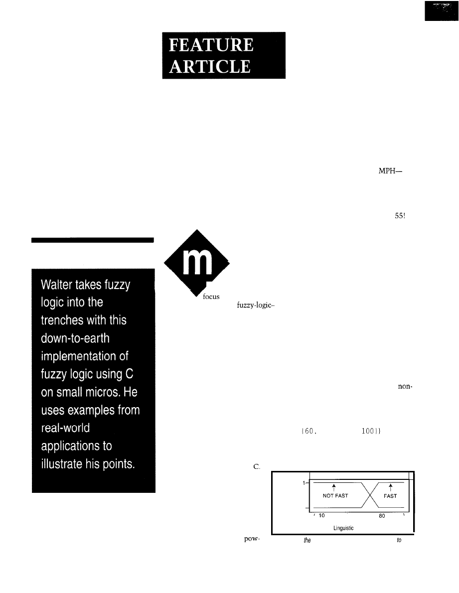
Walter Banks
Fuzzy Concepts Using C
uch of the power
of fuzzy logic comes
‘from its ability to
on specific areas of
interest. In many cases,
based systems can produce superior
results with significantly lower resolu-
tion than congenital approaches to
problem solving.
A lot has been written about fuzzy
logic as another programming paradigm,
but fuzzy logic is now regularly mixed
with conventional code in many appli-
cations. Fuzzy-logic operators are the
formal method of manipulating lin-
guistic variables.
Each of us may differ about what
counts as fast. But, at some speed, we
all say that it is not fast, and at some
other point, we agree that it is fast.
In the space between fast and not
fast, the speed is, to some degree, both.
The horizontal axis in Figure
1 shows
the measured or crisp value of speed.
The vertical axis describes the degree
to which a linguistic variable fits the
crisp measured data.
I can describe temperature in a
graphical way with the declaration:
This article is primarily aimed at the
eight-bit embedded-system developer
who is using a high-level language to
implement an application. The notation
in the fuzzy examples uses the syntax
of Fuzz-C, a C preprocessor that trans-
lates mixed fuzzy and C into
LINGUISTIC
Speed TYPE unsigned
int MIN 0 MAX 100 {MEMBER FAST
80, 100,
This declaration describes both the
crisp variable Speed as an unsigned int
There is no need or reason
(other than convenience) to use
this preprocessor. The examples
show the direct relationship
between fuzzy expressions and
C. My main point: fuzzy logic
doesn’t need special hardware
Degree
of
Membership
0
Central to fuzzy-logic manipulations
are linguistic variables. Linguistic vari-
ables are nonprecise variables that
convey information.
I
can say, for example, that I drove
to work fast or that I drove at the speed
limit. The first description depicts
behavior that borders on reckless. The
second portrays me driving a profile of
time, space, and different speeds on
the expressway and residential roads.
Depending on context, driving at the
speed limit can have other interpreta-
tions as well. If the expressway speed
limit is 55 MPH, then it might mean
that I’m driving close to 55
perhaps 52 or 58 with some distribu-
tion around 55. My attention to the
exact number may be changed by other
factors. Known police-radar locations
often limit my speed to an exact
Linguistic variables in a computer
require there to be a formal way of
describing the linguistic variable in
crisp terms the computer can deal
with. The graph in Figure
1 shows the
relationship between measured speed
and the linguistic term FAST.
0
20 30 40 50 60 70
90 100
Speed (MPH)
Variable FAST
or software, and it offers a
Figure l--Here
linguistic
variable FAST
is compared the
erful tool for problem solving.
crisp speed, producing a degree of membership.
3 2
Issue
88
November 1997
Circuit Cellar INK@
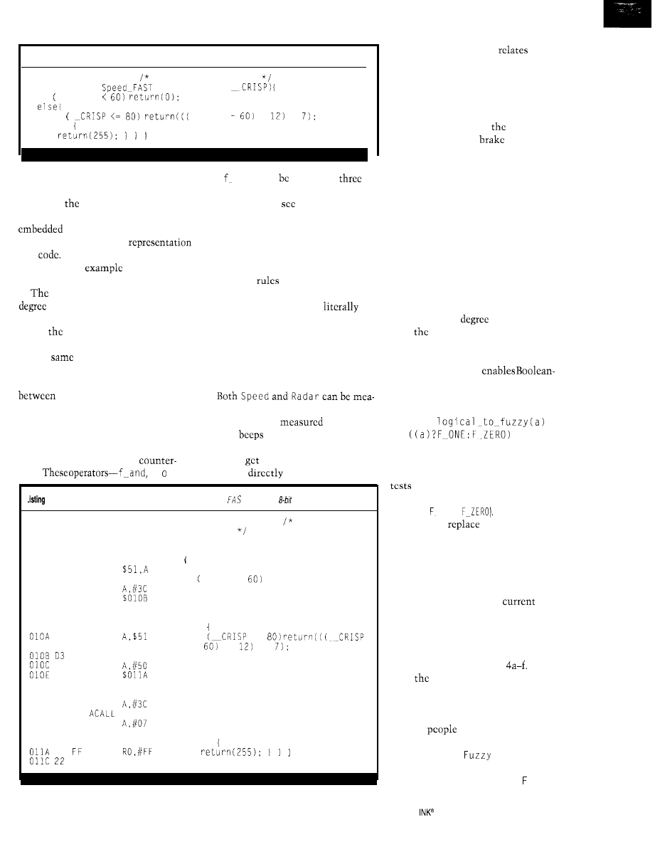
Listing l--This code fragment determines the degree of membership of FAST in the variable Speed.
unsigned int Speed:
Crisp value of Speed
unsigned char
(unsigned int
if
CRISP
if
CRISP
*
+
else
and a linguistic member
FAST
as a
trapezoid with specific parameters.
If I add
linguistic variable
FAST
to a computer program running in an
controller, I need to be able
to translate the graphical
into
The C code fragment in
Listing
1
is an
of how this
might be done.
function
Speed FAST
returns a
of membership scaled between
0 and 255. This type of simple calcula-
tion is
first tool required for calcu-
lations of fuzzy-logic operations.
The
code can be translated to
run on many different embedded mi-
cros. The generated code for converting
crisp and fuzzy is fast and
easily incorporated into embedded
applications (see Listing 2).
Central to the manipulation of fuzzy
and
no
t-can defined as
macros to most embedded-system C
compilers as you
in Listing 3.
FUZZY EXPRESSIONS
Fuzzy expressions describe at a
higher level how actions are to bc
performed. Implementing many of
these fuzzy
in an application
results in a behavior.
This statement can read
and
evaluated with considerable precision:
IF Speed IS FAST AND Radar IS
DETECTED
THEN Brake IS ON:
sured as crisp values. Radar-detector
relevance can be
by the rate
of little
the detector emits as
you
variables are fuzzy-logic operators that
pass the industrial park or by the loud
parallel their Boolean-logic
tone you
when the cop points the
parts.
f r,
radar gun
at your car.
P-Here’s an implementation example of degree of membership of Ton a typical
microcontroller.
0050
unsigned int Speed: Crisp value
of Speed
unsigned char Speed-FAST (unsigned
int CRISP)
0051
0100 F5 51 MOV
0102 D3
SETB C
if CRISP <
return(O):
0103 94 3C SUBB
0105 40 02 JC
0107 E4
CLR A
0108 22
RET
else
E5 51 MOV
if
<=
*
+
SETB C
94 50 SUBB
40 08 JC
0110 E5 51 MOV
A,$51
0112 D3
SETB C
0113 94 3C SUBB
0115 31 46
$146
0117 24 07 ADD
0119 22
RET
else
78 MOV
RET
A simple calculation
the
crisp values to the fuzzy range between
fuzzy 0 and fuzzy
1.
Fuzzy expressions
arc also evaluated between fuzzy 0 and
fuzzy
1.
The fuzzy result of the controlling
expression determines
degree of
braking required. A
value of
fuzzy 0 is no brake pressure, whereas a
value of fuzzy
1
is full braking. It’s
important to note that many of the
linguistic conclusions arc a result of
the general form of the above equation.
FROM CRISP TO FUZZY
Computations performed in the
fuzzy domain must consistently trans-
late logical operations in the crisp
domain to degrees of membership in
the fuzzy domain. Much of this article
is devoted to practical implementations
of developing a
of membership
from
crisp data.
The simplest translation is convert-
ing basic Boolean 0 and
1
data to fuzzy
0 and
1.
This macro
logical comparisons to be made in
fuzzy-logic expressions:
#define
This C macro converts a logical
value to a fuzzy 0 or fuzzy
1.
It simply
for logical
1
or 0 and replaces the
Boolean-logical value with a fuzzy
1 or
0 (i.e., ONE,
First, you
the crisp equality
comparison with a fuzzy comparison
that accounts for a particular range of
data. Then, you base a comparison on
three data values-the comparison
point, the range until the comparison
has failed (delta), and the
vari-
able value.
Delta is the distance to a value
where the current comparison ceases
to be important. Consider for a moment
the definitions in Listings
In each
case,
delta value returns a fuzzy 0
or fuzzy
1,
and any further deviation
from the center point does not change
the result.
Most
have a good sense of
the delta required by an application.
Figure 2 shows a
Equal
rela-
tionship to the crisp domain. As List-
ing 4a shows, the definition of u z zy
Circuit Cellar
Issue 88 November 1997
33
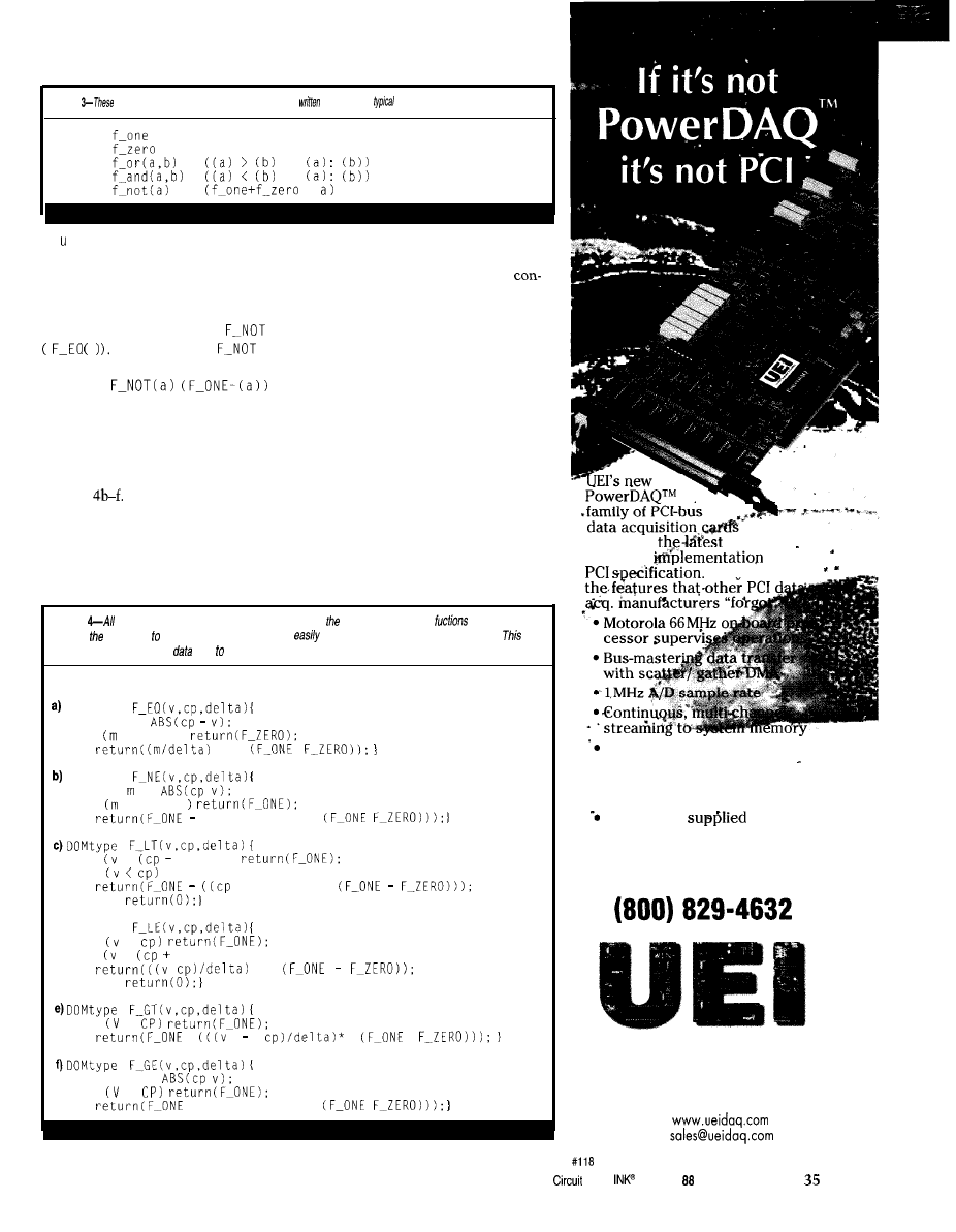
Listing
linguistic variables andoperafors
in C
define
Boolean
operations.
#define
Oxff
#define
0x00
#define
?
#define
?
#define
Eq a 1 can be easily
implemented on
small eight-bit microcontrollers is
most small microcomputers.
attractive.
This technique can be extended to
There hasn’t been a universal
normal arithmetic comparisons. In the
following example,
Fuzzy Not Equal
has the same membership as
v
The definition of
is:
#define
All of the normal crisp identifiers
can be used in the fuzzy domain. Mem-
bership functions for each of the nor-
mal crisp comparisons are given in
Listings
some form of exponential functions on
The implementations for the fuzzy
numerical comparisons all use simple
linear functions to calculate the degree
of membership. The merits of using
sensus, but power functions can express
emphasis. For instance, we might say a
long fly ball is N
E A R L Y
a
home run and
a ball that traveled to the warning
track is
VERY-NEARLY
a home run.
Most exponential functions can be
implemented as the sum of a series. For
example, a reasonable implementation
for
VERY-NEARLY can
be made with
the definitions in Listings 5a and 5b.
just described) has a degree of 1. Such
The linguistic function has two
slopes with an intersection halfway
from delta to the setpoint. Exponential
functions can be implemented by de-
grees, where a single linear function
has a degree of 0 and
VERY-NEARLY (as
Listing
normal arithmetic comparisons can be made in
fuzzy domain. Using
such as these
enables developer make close comparisons and
mix linguistic operations with crisp ones.
effectively adds a linguistic
type a developer’s fool box.
typedef DOMtype unsigned char
DOMtype
long m =
if > delta)
*
DOMtype
long =
if > delta
((m/delta) *
if <
delta))
if
v/delta) *
else
d)DOMtype
if <
if <
delta))
*
else
if <
long m =
if >
((m/delta) *
.
gives you
and most
complete
of the
Thev include
Simultaneous analog and digi-
tal input and output
l
Clean 32-bit drivers for
l
Windows 95 &Windows NT
DLL library
with each
board (includes source code)
Call
today for your free catalog:
United Electronic Industries
10
Dexter Ave, Watertown,
MA 02172
Tel: (617) 924-1155
Fax: (617) 924-1441
internet:
E-mail:
Cellar
Issue November 1997
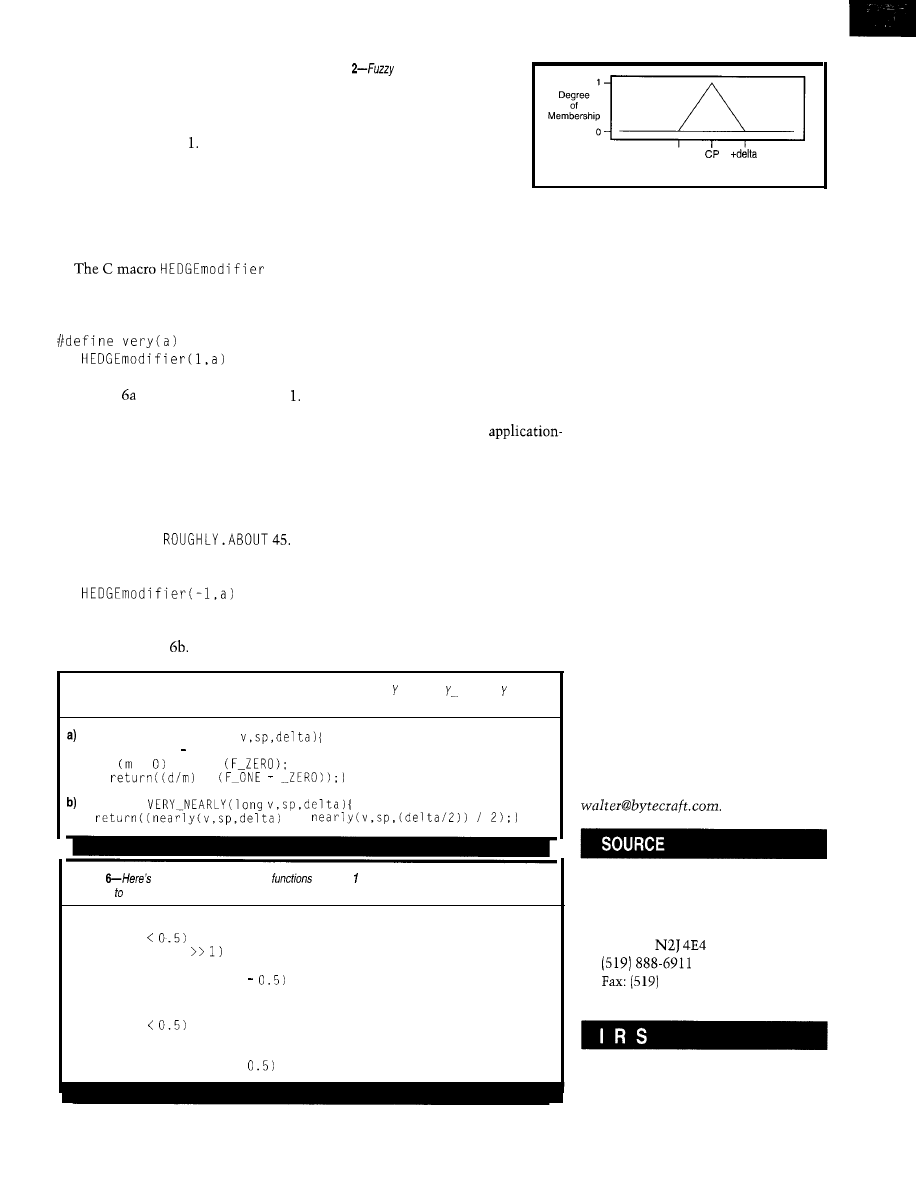
implementations can be automated
with reasonable compilers.
Degrees of membership normalize
the structure of the data to be scaled
between fuzzy 0 and Exponential
functions can be applied in series with
degrees of membership to emphasize
or deemphasize membership functions
in application code.
HEDGE MODIFIERS
specifies the hedge v e ry as being of
order
1
(single break in power function):
Listing defines a hedge of order
Note that this function is easily imple-
mented on most small microcomputers.
Negative hedge modifiers describe
such concepts as
ROUGH LY.
I might say
a certain man is about 45 and be refer-
ring to someone within a year or two of
45. I can then describe a broader range
ofindividualsas
#define ROUGHLY(a)
A hedge modifier of order
-1 is de-
fined as in Listing
As an alternative,
Figure
equality checks the area
around the c omp a r e value for close
matches. The better the match, the higher the
degree of membership.
-delta
Fuzzy Equal
hedge functions can be implemented
as simple table look-up functions with
at most some linear interpretation.
Hedge functions may be used with
any membership function and may be
cascaded to strengthen emphasis. Two
hedges of order
1
in series yield a hedge
of order 3. I haven’t needed to imple-
ment hedges other than
1, 0,
and
-1.
Hedge functions permit the applica-
tion designer to formally add emphasis.
Here, hedge functions have a common
mathematical basis and an
specific meaning. And, they smooth
out the roughness in descriptions.
The quest for improved accuracy in
the last twenty years has mostly been a
quest for improved numerical relevance.
The fuzzy domain always focuses on
the relevant data and limits to fuzzy
1
or 0 when the data ceases to be relevant.
IN THE REAL WORLD
The techniques I’ve described go a
long way toward describing a problem
Listing C--Exponential functions can be implemented by degrees. N EA R L and V E R N EA R L represent
different levels of hedge functions.
DOMtype NEARLY
(long
long m = sp v;
if < return
*
DOMtype
+
Listing
the general form for hedge
for order and order -1. Hedge functions can be
cascaded increase the extent of a condition.
a) hedge order 1 translation is
if (in
return (in
else
return (0.25 + (in
* 1.5):
b) hedgemodifier
order -1 translation is
if (in
return (in * 1.5
else
return (0.5 + (in
* 0.5);
in an effective and natural way. Crisp
comparisons are necessary in some
contexts. But in the last few years,
we’ve discovered many more applica-
tions for fuzzy logic than we had previ-
ously imagined.
I am primarily in the code-creation
business and recognize that most appli-
cation software is written on conven-
tional computers with conventional
instruction sets. All of the definitions
in this article can be implemented on
even basic eight-bit micros using ac-
ceptably few instructions, typical shifts,
adds, and comparisons-things that
eight-bit micros do well.
It’s practical to build fuzzy-logic
control systems in consumer appliances.
Against conventional implementation
techniques, fuzzy logic competes well.
In general, my experience has been
that fuzzy logic is less math intensive
and more logic intensive than tradi-
tional implementations.
q
Walter
Banks is president of Byte
Craft Limited, a company specializing
in software tools for embedded micro-
processors. His interests include highly
reliable system design, code-generation
technology, programming language
development, and formal code-verifi-
cation tools. You may reach him at
Fuzz-C, C
8051
compiler
Byte Craft Limited
421 King St. N
Waterloo, ON
Canada
746-6751
www.bytecraft.com
407
Very Useful
408 Moderately Useful
409 Not Useful
36
Issue 88 November 1997
Circuit Cellar INK@
PC/l 04 I/O
The
AIM1
is a PC/l 04 I/O
expansion module that uses an optoisolated serial bus
to connect with its analog subsystem. It provides 8
isolated digital inputs, 2 analog outputs, and 16 single-ended
or 8 differential analog inputs. This combination gives the user
everything required to interface with most sensors and actuators
with enough digital capability to monitor switches and controls.
The board features a conversion time of 500
which
is equivalent to converting up to 2k samples per second-fast
enough for many general-purpose industrial instrumentation require
ments. The analog-input section is based on a flexible
ADC.
The two precision analog-output channels are provided by a
DAC. Each channel can update in 320 and output control signals
or waveforms over a bipolar range of -5 to
V or
current loop sink. Both analog functions offer 1 -kV isolation between
the PC/l 04 system and the electrical system under control.
The digital inputs
conventional optoisolation and can switch
signals over a 10-30-V range. Each channel includes built-in
filtering with a
1 0-ms
time constant and can interface
digital signals to a maximum frequency of 50 Hz.
The
I/O board sells for $295.
Arcom Control Systems
13510 S. Oak St.
l
Kansas City, MO 64145
(816) 941-7025
l
Fax: (816) 941-7807
The
em-
bedded controller contains all
the system-level resources
needed in most embedded ap-
plications. Designed around an
engine, the
board features 1 -MB
RAM/ROM/flash space, watch-
dog timer, EEPROM,
supply monitor, and real-time
clock. It has two RS-232 serial
ports, an alphanumeric LCD port,
and a keypad port. Peripheral
support is available from more
than 20 interface products.
The
features
a wide range of development
software. An embedded, multi-
tasking compiled BASIC ex-
ecutes up to five times faster
than
C is sup-
ported using Paradigm’s remote
debugger, extensive iibraries
from
and Borland or
Microsoft C compiler.
DOS is also available.
EMBEDDED CONTROLLER
The PC/ 104
compatible bus provides ac-
cess to the most commonly used
signals. The VAST
Ad-
dressable Synchronous Trans-
fer) network connector accom-
modates a variety of
low-power peripherals. An
optional RS-485 adapter con-
verts one of the two RS-232
ports to either a two- or
wire RS485 network.
The
sells for
$159
in single quantities or
$1 14 in
quantities.
Technology, Inc.
11465 W.
Frontage Rd. N.
Wheat Ridge, CO 80033
(303) 422-8088
Fax: (303) 422-9800
l
38
CIRCUIT CELLAR
INK
1997
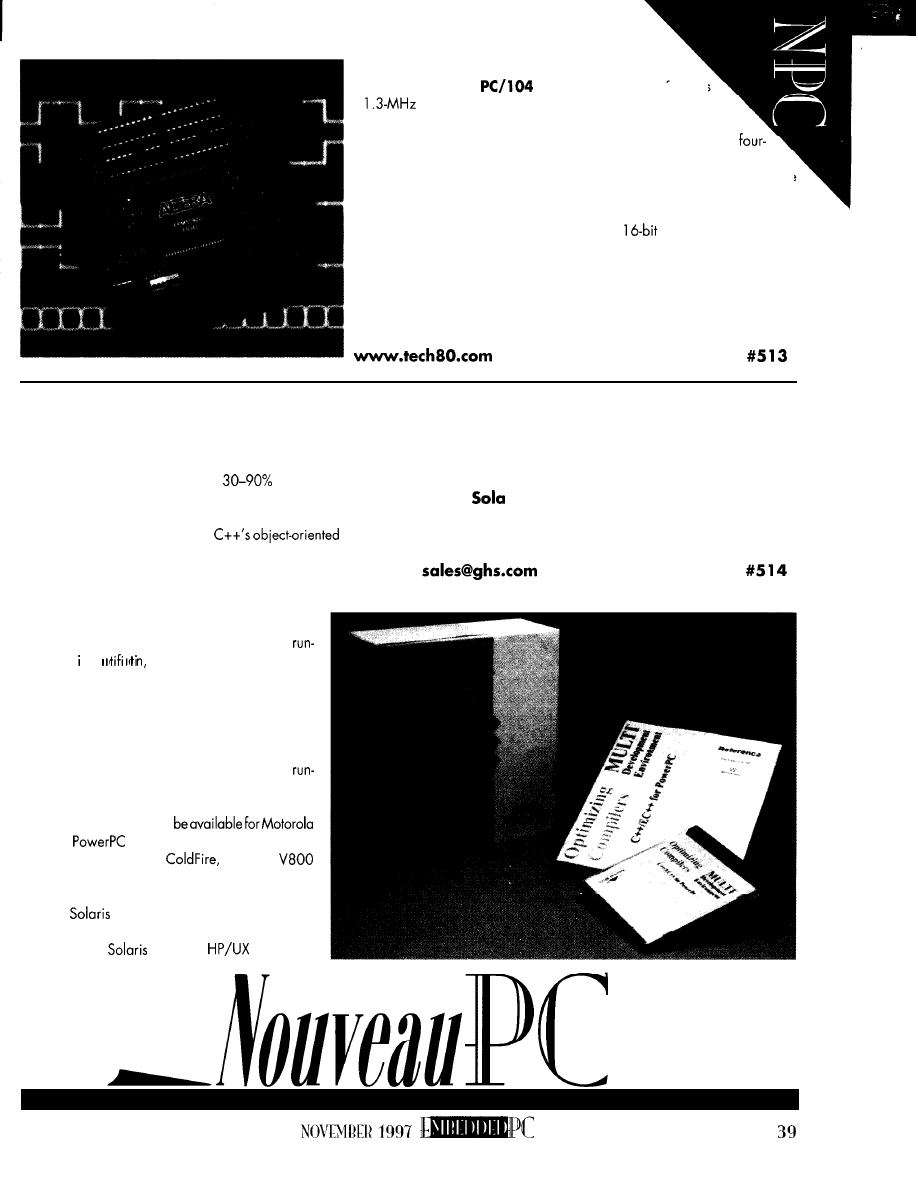
PC/l 04 ENCODER INTERFACE
The
Model 5912
Encoder Interface
features
a
quadrature input rate with 24-bit presettable counters
from up to four incremental quadrature encoders or pulse sources.
Inputs may be single-ended or differential and are conditioned by a
stage digital filter. The 5912 generates interrupts on index pulse, over/
underflow, or compare value match, and it decodes Xl, X2, and X4 to provide
higher encoder resolution.
Software libraries are compatible with most C, C++, Visual Basic, Visual
C++, and Turbo Pascal compilers and include
drivers for Windows 3.1.
The Model 5912 costs $425 in a single-axis configuration. A development
kit is also available for easy implementation in development and prototype stages.
Technology 80, Inc.
658 Mendelssohn Ave. N
l
Minneapolis, MN 55427
(612) 542-2980
l
Fax: (612) 542-9785
EMBEDDED C++ COMPILER
The Embedded C++ Compiler
(C++/EC++)
is a subset of C++
optimized for resource-constrained embedded applications. Imple-
mented as a user option within the C++ compiler’s broader
framework, the compiler achieves a
improvement in code
size and run-time efficiency over full-blown C++, particularly for
applications containing I/O of any kind.
C++/EC++ provides many of
facilities,
which enhance code reusability and simplify the partitioning and
maintenance of complex code. However, it omits a number of C++
features that aren’t essential for most embedded
applications but significantly increase code size
and impair run-timeefficiency. Included are multiple
inheritance, virtual base classes, exceptions,
time type en
virtual function tables, and
d
mutable specifiers.
C++/EC++ is fully integrated with the MULTI
Development Environment, which automates every
aspect of embedded software development. Featur-
ing a window-oriented editor and an RTOS-aware
source-level debugger, MULTI also includes a
timeerrorchecker, application profiler, and project/
version control.
Thecompilerwill initially
68k and
family processors, with versions
for the Hitachi SH, MIPS,
and NEC
processors following later in the year. The compiler
will also produce native code for workstations
running
2.5. Development host options in-
clude PCs and workstations running Windows NT,
Windows 95,
2.5, and
10.0.
Windows NT and Windows 95 versions of the C++/EC++
compiler cost $3900. Unix versions are priced at $5400.
Green Hills Software, Inc.
30 W.
St.
Santa Barbara, CA 93101
(805) 965-6044
Fax: (805) 965-6343
l
www.ghs.com
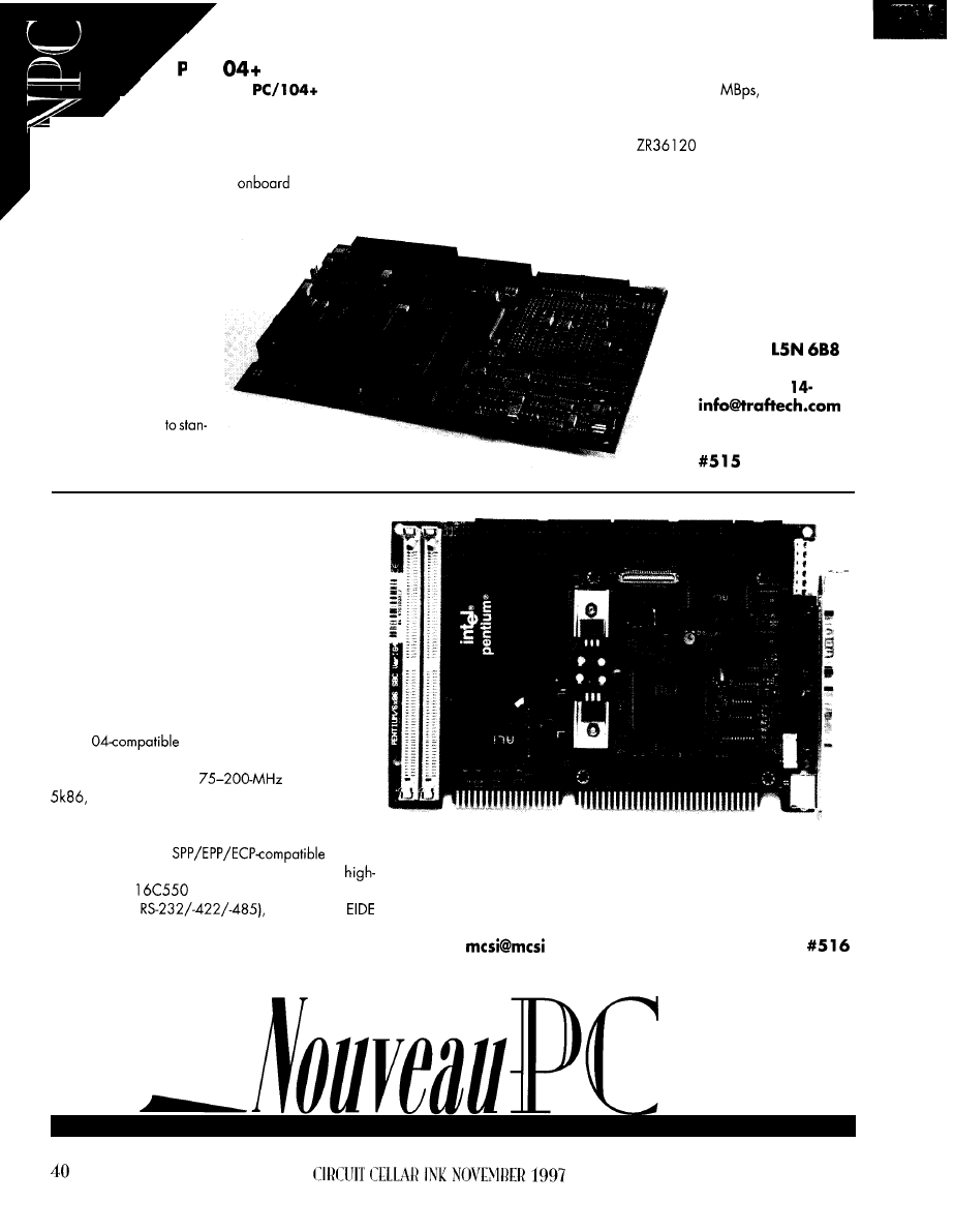
PC/l
MPEG DECODER
.
The Traftech
MPEG Decoder
7
Card
supports full audio/video synchronization
with MPEG-1 system-layer decoding. It demultiplexes
the MPEG bitstream, extracts the time stamps for the video
and audio bitstreams, buffers both compressed audio and
video data, and provides
audio decoding while
maintainingfullsynchronizationofaudioandvideosignalsthrough-
out. It has built-in compen-
sation for any differences
in processing delay of the
two signals.
Card features include
full video CD 2.0 support,
special display modes
(e.g., pause, freeze, and
slow motion), and auto-
matic frame-rate conver-
sion from all common
MPEG picture rates
dard PAL or NTSC display
frame rates. In addition,
high-quality decoded video at a rate of 5
error detection,
and concealment features with a direct interface to 5
12
KB of
DRAM are included.
The card uses the Zoran
PCI-bus controller, which
permits the MPEG decoding to be handled at the maximum bus
bandwidth of the 32-bit PCI bus. The card is plug-n-play compatible
for seamless insertion into Windows 95 and Windows NT appli-
cations.
The MPEG Decoder
Card sells for $595
Traftech, Inc.
698 1 Millcreek
Mississauga, ON
Canada
(905) 814-1293
Fax: (905) 8 1292
www.traftech.com
HALF-SIZE SINGLE-BOARD COMPUTER
The PC-560 is a half-sized, Pentium-based SBC that
contains all the basic elements found in a standard IBM
PC/AT-compatible desktop computer system plus some
unique features making it ideally suited for industrial
applications. It can be configured to operate without a
display and keyboard, so it’s a perfect solution for a
wide variety of industrial applications.
This computer features a high-performance I/O con-
troller, watchdog timer, PCI SVGA/flat-panel controller,
and single 5-V power-supply operation. It also includes
a PC/l
interface port, so it can operate
in a stand-alone configuration.
The PC-560 supports
Pentium, AMD
and Cyrix 6x86 processors. Its 1 MB of video
memory enables a resolution of 1024 x 768 at 256
colors or 1280 x 1024 at 16 colors. Standard I/O
features include an
bidirec-
tional parallel port, dual floppy-disk port, two
performance
serial ports (COM2 can be
configured for
and two PCI
hard disk ports that support up to four drives.
The PC-560 is priced at $725.
Micro Computer Specialists, Inc.
25986 Fortune Way
Vista, CA 92083
(760) 598-2
177
Fax: (760) 598-2450
1
.com
l
www.mcsi 1 .com
Applications
Tom admits that
Windows
can’t possibly
application, he points out the niches it can fulfill. And, he
meets the marketplace demand for more standardization
indows CE, Microsoft’s latest addi-
However, it delivers a serious and con-
tinuing blow as the embedded market must
recognize that the islands of functionality
are disappearing and connected applica-
tions are the future.
API is expanding all the time, adding im-
provements to the development environment.
fit every embedded
demonstrates how it
between products.
tion to the Windows family of
was
unveiled in late 1996. Although it only ran
on one type of device-the hand-held
each device proudly touted its presence by
displaying the Windows CE logo and run-
ning familiar-looking desktop applications.
It’s certainly a technical feat to develop
an OS that can run scaleddown versions of
Microsoft Excel, Word, and Internet Ex-
plorer in 4 MB of ROM and 2 MB of RAM.
But, you’re probably wondering what this
has to do with general embedded systems.
Windows CE will be seen initially on
portable and mobile applications. But, its
positioning, pricing, and footprintwill have
an impact on the entire embedded market.
Microsoft has ratcheted deeper into the
embedded market, delivering a platform
for the industrial automation and communi-
cations markets as well as the
medical and games markets.
Is this the end of the proprietary RTOS
market? Well, not this year, and certainly
not for all applications.
42
Time-to-market pressures are increasing
for embedded systems, and the use of a
commercial OS has huge advantages in
leveraging off-the-shelf components. The
use of a commercial embedded OS with
ties to the desktop has the opportunity to
leverage even more.
The leveraging argument applies to
know-how as well as code, and Microsoft
is quick to pointoutthe more than 500,000
Win32 developers. Microsoft wants to re-
duce the technical barriers that prevent
Win32 developers from applying their
expertise to Windows CE.
Existing commercial
in the embed-
ded arena have also felt market pressure to
provide support for the Win32 API. Many
RTOS vendors have responded with an
emulation layer. But, the staying power of
thisapproach
Win32
1997
In this article, I describe some Windows
CE features to
help
you evaluate its suitabil-
ity for your next embedded project. I also
discuss the real-time functions and needed
enhancements expected to be available. I
hope
you’ll
gain insight into how Windows
CE device drivers are developed and, most
importantly, how to get started.
I N E M B E D D E D P R O J E C T S
The embedded market is large and
diverse, and it’s not unusual for an OS to
target specific areas. So, the first question is
whether Windows CE addresses the
ketsector appropriate for your next project.
Windows CE has many features to
choose from-especially in communica-
tion, development environment, and user
interaction. Table
1
lists some of the more
important features announced for
this
year.
Microsoft expects to provide two Win-
dows CE releases per year and is working
with
to develop Windows CE for
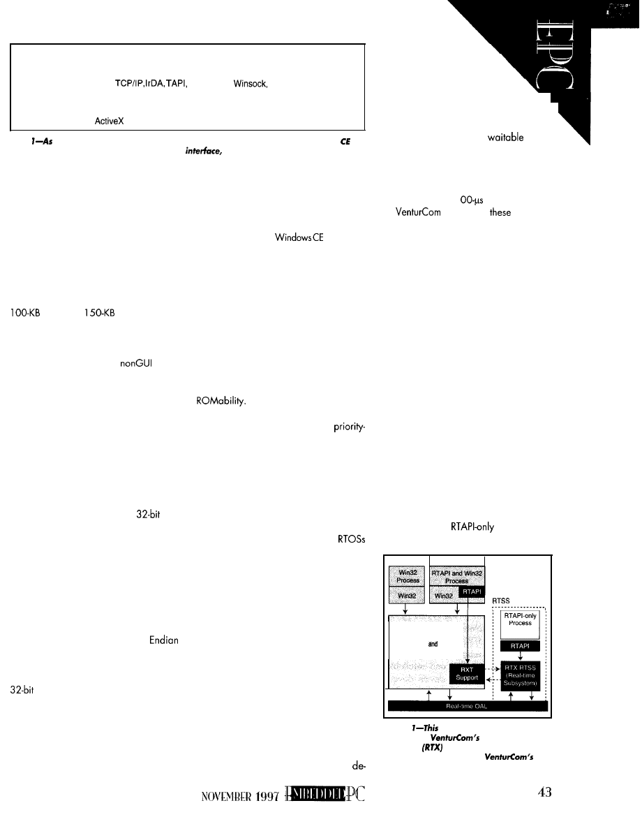
Kernel
Fixed priority scheduling, power management, PC Card services, Win32
process/thread and virtual memory model ROM execute in place,
demand paging from compressed ROM
Communication
PPP
Unimodem,
Remote Access API,
LAN support (NDIS drivers and SMB redirector)
USER and GDI
Overlapping windows, event management, user interface controls,
dialog boxes, interprocess communication, UNICODE, 24-bit color
Development
subset, Java, Visual Basic subset, MFC
Table
well as
having the features expected of an embedded kernel, Windows
2.0
excels in the areas of communications, user
and development environment.
new types of devices. Third parties will also
provide new components to be added to
the basic kernel configuration.
As you’d
expect from
an embedded OS,
Windows CE is broken down into numerous
components that can be configured into a
system. The selected componentsaffect RAM/
ROM requirements as well as royalties.
The memory requirements of a mini-
mally configured Windows CE depend on
who
you talk to. Configurations as small as
RAM and
ROM have re-
portedly been built.
A more typical configuration support-
ing the registry-RAM/ROM file system,
kernel debugger, a simple
appli-
cation, and device driver-can require
250 KB of RAM and 500 KB of ROM. A full
configuration, as you might find in a hand-
held PC, may need 2 MB of RAM and 4 MB
of ROM (including applications).
Processor support limits Windows CE to
new 32-bit designs. Although Windows CE
runs on more processors than any other
Microsoft OS, it supports a fraction of the
processors used in embedded systems.
Fortunately, support has been announced
for many of the next-generation
pro-
cessors likely to be in embedded systems.
But, the low power and high integration
of the many processors supported by Win-
dows CE seem to reflect its initial emphasis
on mobile computing. I’m hoping this situ-
ation will change as vendors realize the
applicability of Windows CE for general
embedded computing.
Architecturally, Windows CE only runs
on processors that are 32-bit Little
with an MMU. The MMU gives Windows
CE the opportunity to contain application
faults, but it limits its use to the higher end
processor families. It’s conceivable
that Windows CE could influence the de-
sign of future processors.
Getting Windows CE support for a
currently unsupported processor is some-
thing beyond most project developers. Full
source code isn’t available, and processor
ports are performed
by
Microsoft
on behalf
of their semiconductor partners.
Becausesourceisn’tavailable, Windows
CE can’t be used in highly critical control
applications. For example, if you design
flightcontrolsystems,
isn’tgood.
For such systems, simplicity is a virtue. You
need source to verify functionality.
Combining a simple real-time execu-
tive, which does have source available, with
Windows CE may address some of these
concerns. VenturCom’s RTX architecture
follows this approach and may take Win-
dows CE into these areas.
H A R D R E A L T I M E
Many embedded applications need
hard real-time performance in addition to
Windows CE has many of the
features you’d expect from an RTOS.
Scheduling is fixed priority
with
inheritance support in its locking protocol.
Interrupt latency is kept low by offloading
most interrupt processing to interrupt service
threads. Multiprocessing and multithreading
are supported as well.
The limit of 32 processes with 32 MB of
virtual address space may be a problem for
some real-time use. But, there’s no limit on
the number of threads, and many
today only
support a single-process model.
There are some gaps, however, with
complex real-time systems. Although it sup-
ports fixed priority scheduling and priority
inheritance, Windows CE only has seven
priority levels. The highesttwo priority levels
are reserved for interrupt service threads.
For systems that share the processor
among a modest number of tasks and inter-
rupt sources, this limited scheduling structure
may suffice. But for many real-time applica-
tions, there aren’t enough priority levels to
adequately manage system activity.
Paging may also be problematic. To
conserve RAM usage, Windows CE com-
presses code and data stored in its RAM/
ROM file system. Compressed code pages
are faulted into RAM, where they’re
compressed before ex-
ecution. For determinism, de
vice drivers aren’t paged, but
pages for other user processes can
be, affecting determinism.
\
Many real-timeapplicationsneed high-
resolution timer services. Windows CE
doesn’t implement Win32
timers,
so the Win32 API limits the time specifica-
tion to 1-ms resolution. Implementation of
the API is often with a clock period ten times
larger. In stark contrast, real-time applica-
tions can require 1
resolution.
will address
and
other
real-time limitations with its RTX architec-
ture, originally developed for Windows
NT (see Naren Nachiappan’s “Embedded
PCs Go Industrial,” INK75 and 77). RTX
defines a real-time API (RTAPI) specifically
for hard real-time use within a Win32
environment and provides a real-time sub-
system (RTSS) that deterministically imple-
ments this API.
RTAPI defines these interfaces in addi-
tion to those provided by the Win32 API:
l
high-resolution clocks and timers
l
fixed-priority scheduling with 128 priori-
ties provided by the RTSS
l
I/O bus and physical memory access
from user processes
l
device interrupts and interrupt priority
setting
l
interprocess communication with sema-
phores, messages, and shared memory
RTX distinguishes between processes us-
ing only RTAPI calls and those mixing RTAPI
and Win32 calls.
processes run
in the RTSS, have deterministic response
Windows CE
Kernel
Drivers
Environment
Figure
diagram depicts the various
modules of
hard real-time ex-
tensions
for Windows CE and their
interrelationships. RTAPI is
real-
time API.
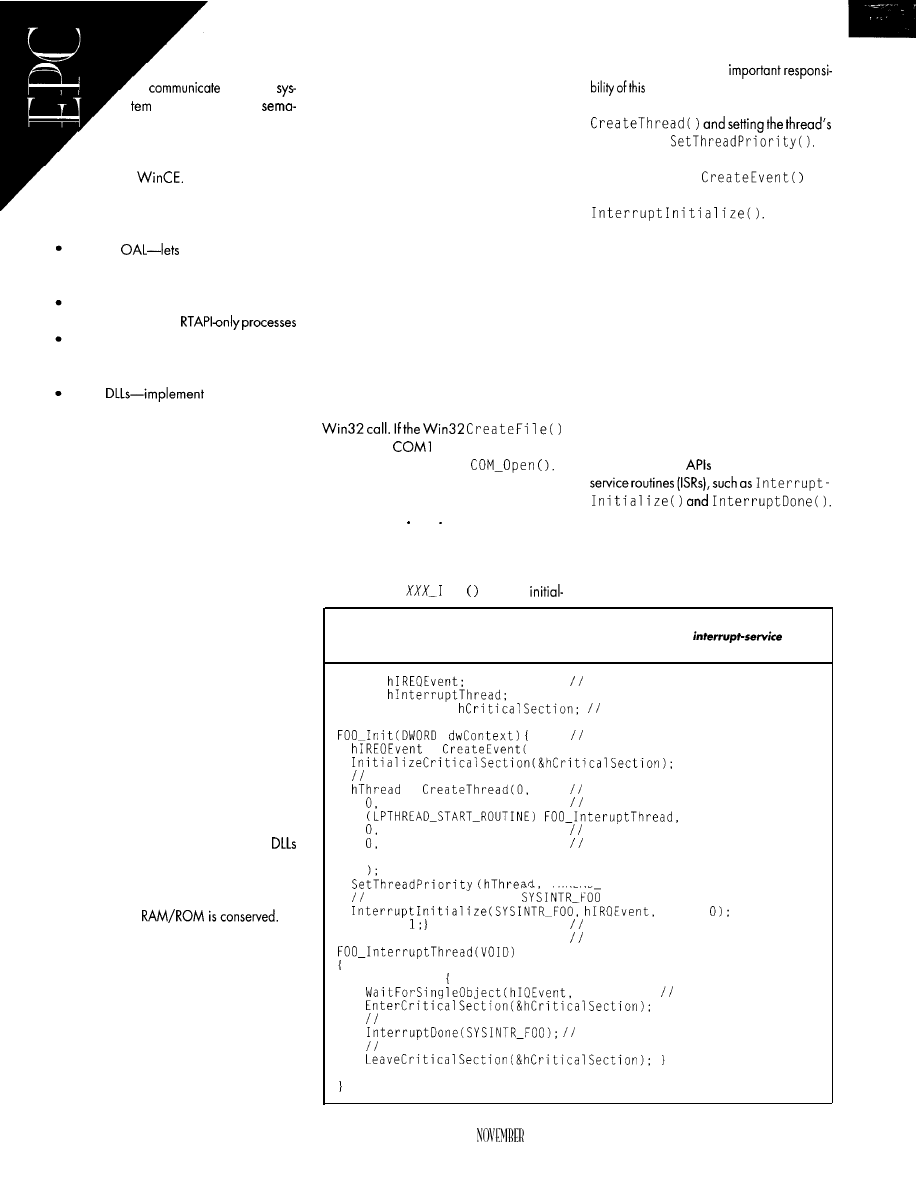
with 128 priorities, and
with
other
processes through
phores, messages, and shared
memory. Processes mixing Win32
and RTAPI calls have the scheduling
limitations of
The basic architecture of RTX shown in
Figure 1 consists of:
real-time
hardware interrupts
be vectored to RTX before being passed
on to Windows CE
RTX RTSS-performs scheduling and other
supportfunctionsfor
RTX support module-provides support
from Windows CE for resources man-
aged by Windows CE
RTAPI
the real-time API
for use with Win32 calls
Using the same real-time architecture for
Windows CE and NT provides interesting
potential for upward expansion. Real-time
NT applications can move to CE to take
advantage of more deeply embedded de-
vices. Conversely, applications that out-
grow the resource limitations of Windows
CE devices can move to NT.
D E V I C E D R I V E R S
Usually, embedded applications largely
consist of custom software. Developing
Win32 software that interfaces with the
user, other processes, or device drivers is
well-documented.
Other than Windows CE supporting a
subset of the Win32 API, the approach for
Windows CE is the same as for Windows
NT. Developing device drivers is different,
but it’s probably already familiar to most.
Unlike NT, Windows CE doesn’t have
an elaborate
API
forwriting device drivers.
CE device drivers consist of Win32
and user threads (see Listing 1). By relying
as much as possible on the Win32 API for
the device-driver interface as
well as appli-
cation code,
Windows CE supports two categories
of device drivers-built in and installable.
I discuss only installable device drivers,
since they have the most flexibility to adapt
to new types of devices.
The basic interface between the CE
kernel and installable device drivers is the
stream interface. It specifies the entry points
provided by the DLL implementing an
installable device driver (see Table 2).
The XXX in the table is unique to each
device driver and associates the device
name with the driver’s entry points. These
entry points are invoked by the CE kernel in
response to system management and to
Win32 applications accessing the device.
Device drivers are accessible to Win32
API through a filename convention. The
Windows CE file system recognizes a
filename consisting of three uppercase let-
ters, a digit, and a colon as a device name.
The letters correspond to the X
XX
prefix
used in the stream interface.
A device driver can be called to man-
age a number of devices it controls. The
digit is a device index the device driver
uses to distinguish among these devices.
Windows CE uses a combination of the
device name and preset registry values to
associate an entry point in a
DLL with a
call specifies
:
as the file
to open, for
example, the kernel calls
Based on information provided in the
registry, the kernel invokes this entry point
from Seri a 1 dl 1 Registry entries for
device drivers are set up as part of Win-
dows CE configuration.
In Windows CE, user threads process
interrupts. The
n i t
interface
izes device
drivers. An
routineistocreatethe Interrupt
Service Thread (IST) using the Win32
priorityvia
The driver is also responsible for creat-
ing an event with
and
registering it with the kernel by a call to
Once the
event is registered, the kernel signals the
registered event every time the interrupt
occurs. The IST merely repetitively waits for
the registered event to occur before pro-
cessing the interrupt.
Windows CE is multithreaded, so it’s
necessary to synchronize the access of
threads to shared data structures. Drivers
use Win32 critical sections for this. For
event notification (e.g., arrival of data from
a device), drivers use Win32 events.
Windows CE goes far with the Win32
API, but additions are needed. Windows
CE adds a few
for use by interrupt
There’s also a routine to disable inter-
rupts, but since interrupt processing is per-
formed by user threads, it’s seldom used.
Windows CE adds an API so device regis-
ters can be mapped into the address space
listing l--This code fragment demonstrates how the Win32 API is used by Windows CE
device drivers. Win32 interfaces are used for synchronization,
thread
creation, and event notification.
HANDLE
HANDLE
Event associated with interrupt
CRITICAL_SECTION
Shared data synchronization
DWORD
Initialize the device
=
NULL, FALSE, FALSE, NULL);
Code to map device registers goes here
=
Security Attributes
Stack Size
Thread Parameters
Creation Flags
NULL
THREAD PRIORITY HIGHEST);
Associate event with
interrupt
NULL,
return
Return success
ULONG
Interrupt service thread
while (TRUE)
INFINITE); Wait for interrupt
Device dependent code to dismiss hardware interrupt goes here
Unmask this interrupt
Code to process interrupt goes here
return TRUE;
CIRCUIT CELLAR INK
1997
44
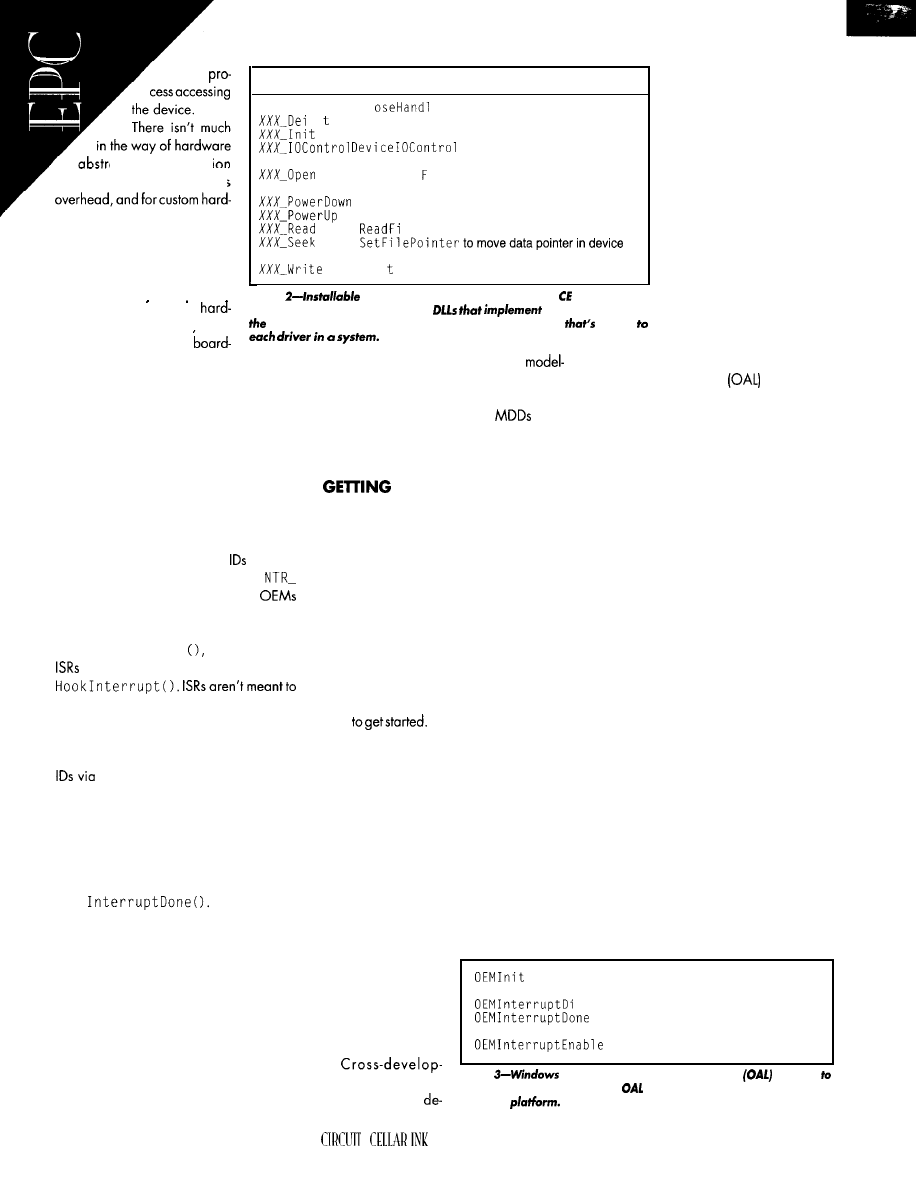
of the
action. Abstracti-..
(e.g., busabstraction) imposes
ware devices, the d e s i g n e r
knows the exact configuration
that has to be supported.
For high-volume devices, it
Interface
Invoked by
XXX-Close
Cl
e to close device (Indirect)
ni
Device Manager to deinitialize device after last use
Device Manager to initialize device for first use
(and by Device Manager) to
send command to device (Indirect)
C r e a
t e i 1 e to open device for reading and/or
writing (Indirect)
OS to power down device
OS to restore power to device
1 e to read data from device (Indirect)
(Indirect)
W r i e F i 1 e to write data to device (Indirect)
pays to optimize out any unused
Table
device drivers, a type of Windows driver with a
generalization trom the
flexible programming mode/, are
the entry points of
ware. For lower volume systems
Stream Interface. The XXX is a three-character prefix
unique
(e.g., thoseaddressed
by
level computers), bus abstractions have a
place and may need to be introduced into
Windows CE.
Windows CE abstracts the identifica-
tion and manipulation of interrupts listed in
Table 3. The OEM Adaptation Layer (OAL)
is responsible for identifying interrupt
sources for the kernel and implementing
routines that let the kernel mask and un-
mask these interrupt sources.
stream interface and exposes a
specific API to be implemented for each
platform Windows CE is ported to. Win-
dows CE provides a number of
in the
OAK (more about that later). The PDD
implements the hardware details.
STARTED
Each source gets an ID as part of porting
Windows CE to a platform. The
for many
standard interruptsources (e.g., SY S I
KEYBOARD) are predefined, and
define others to support their platforms.
What you need to get started depends
on whether you’re writing user applica-
tions for an existing device, creating drivers
for new peripherals, or developing a new
Windows CE-based system.
Early in Windows CE initialization, the
kernel calls 0 EM In i t
which registers
by calling the Windows CE-provided
do much processing in Windows CE. Typi-
cally, they merely identify the source of the
interrupt and return the interrupt ID.
To start developing Win32 user applica-
tions for Windows CE, you need an ‘x86
PC running Windows NT, Visual C++ 5.0,
and Visual C++ for Windows CE. This last
item provides the cross-development tools
for all supported CE platforms.
Drivers associate events with interrupt
I n t e r r u p t I n i t i a l i z e O . O n
the return of an ISR, the kernel signals the
event associated with the interrupt ID re-
turned
by
the
ISR. When an interrupt occurs,
only the applied interrupt is masked-all
other interrupts remain unmasked. The ap-
plied interrupt remains masked until the IST
calls
You may not even need the target hard-
ware
The tools include emula-
tion environments for hand-held PCs and
other Windows CE devices Microsoft has
developed hardware specifications for.
Though hardware abstraction is mini-
mal, there are mechanisms for code reuse.
Reuse is obviously important for reducing
development time and code size. Many
Windows CE drivers are split into a plat-
form-independent part--the Model Device
Driver (MDD)-and a platform-specific
part--the Platform Device Driver (PDD).
Given its wide availability, VC++ for
Windows CE is the best place to look for
answers regarding the subset of Win32
available in Windows CE. For the most
part, the Win32 API available on Win-
dows CE is a subset of that available on
Windows NT, but there are some differ-
ences in function noted in the online
documentation.
If
you’re migrating
an application from
Windows NT to CE.
The MDD implements the behavior ex-
pected from a class of device (e.g., a serial
port). It interfaces to the kernel using the
VC++ for Windows
sabl e
Mask the specified interrupt
CE is the place to
Called indirectly by interrupt,
done to unmask specified interrupt
start.
Unmask the specified interrupt
ment tools support
Tab/e
CE has an OEM abstraction layer
adapted
d o w n l o a d a n d
each platform. Here are some
routines that must be implemented
for each
46
NOVEMBER 1997
bug through a serial/network
connection to the target de-
vice. Full source-code debug-
ging is supported. With some
care, applicationscan be built
to run natively on Windows
NT as well as emulated and
actual Windows CE plat-
forms.
For serious system devel-
opment, you need the OEM
Adaptation Kit (OAK), which
enables developers to config-
ure and build kernels. It in-
cludes Windows CE binaries
and libraries for each of the
supported processors and sources for the
OEM Abstraction Layer
and drivers.
The OAL abstracts the hardware plat-
form for Windows CE, similar to the Hard-
ware Abstraction Layer of Windows NT.
Sources to the MDD and PDD drivers are
provided, usually for the devices that are
present on the Windows CE hardware
reference platforms provided by semicon-
ductor manufacturers.
The OAK not only builds kernels but also
a development environment for applica-
tions. The Win32 API depends to a small
extent on which components have been
configured into the kernel.
As a side effect of building a kernel,
headers and libraries corresponding to the
configured components are built, conserv-
ing target resources but requiring applica-
tion developers to be aware of the specific
device it’s being developed for. This situa-
tion is unavoidable for embedded systems.
And, there are other issues you need to
be aware of. The infrastructure for develop-
ing systems using Windows CE on the
small scale is undergoing growing pains.
The early hardware reference platforms for
Windows CE are very much reference
platforms for hand-held PC designs.
To date, no board-level Windows CE
products are available, putting Windows
CE development out of the reach of many
small-scale designs since custom hardware
Perform platform initialization
(initialize interrupt vectors, etc.)
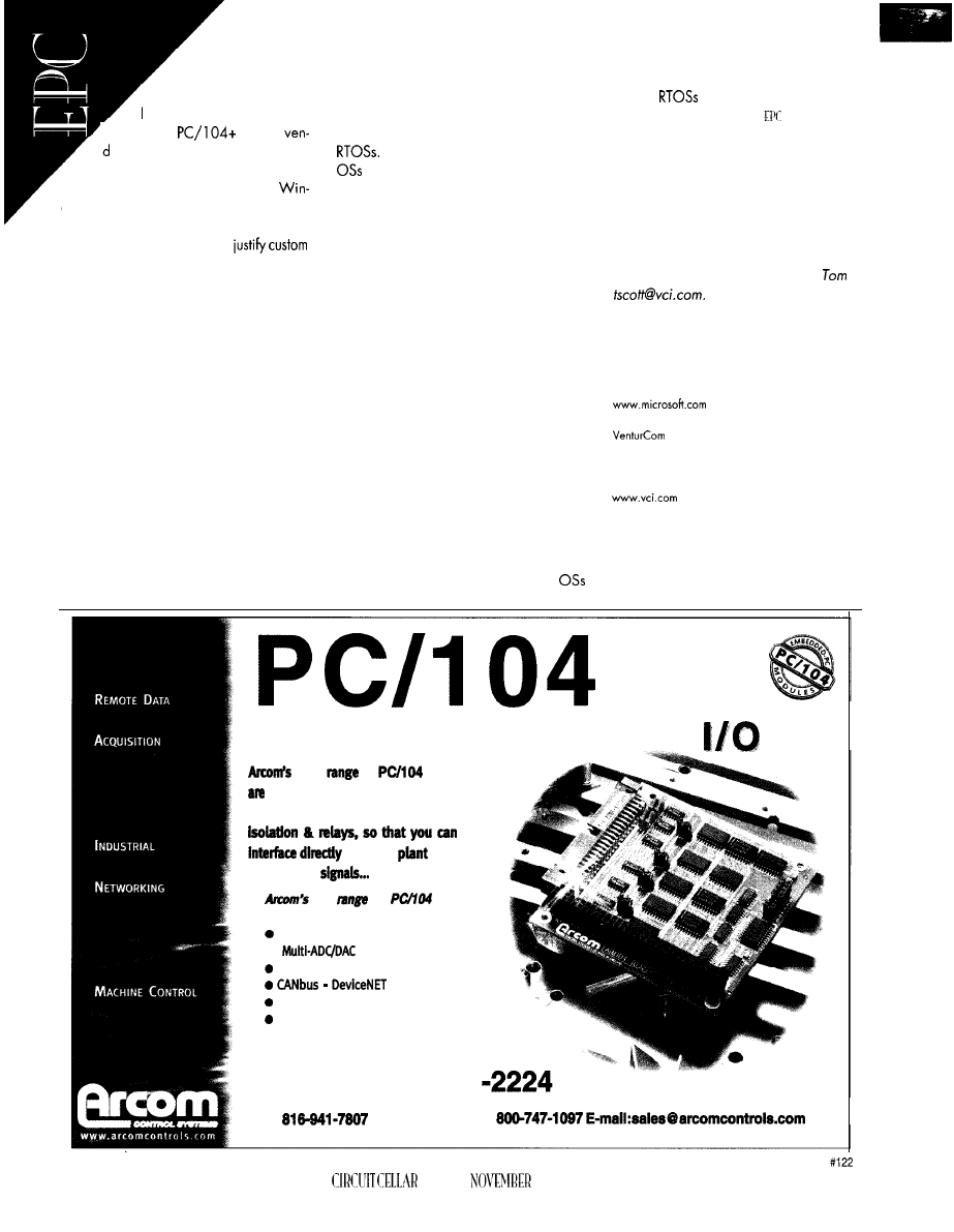
must be built. Don’t
expect this situation to last
’
ong, however, as Compact-
PCI and
system
ors eye Windows CE for new
opportunities.
The introduction of board-level
dows CE products will necessitate changes
in the existing development model. Projects
that don’t have thevolumes to
hardware also need an easy way to config-
ure kernels. In this case, VenturCom’s Com-
ponent Integrator (Cl) will have wide
applicability for Windows CE.
Cl is a GUI-based tool developed for
componentizing Windows NT.
It
runs on
an ‘x86 workstation running Windows NT,
the same host system as the Windows CE
development environment, and can build
highly customized Windows NT kernels.
The heart of Cl is a knowledge base
describing the files, registry entries, and
dependenciesassociated with the hundreds
of components of Windows NT. VenturCom
will be extending this to Windows CE
components to enable Cl to build Win-
dows CE as well as Windows NT targets
for use in embedded systems.
WINDOW TO THE FUTURE
With Windows CE, Microsoft has pro-
vided a base technology targeted at the
embedded-systems market and traditional
Unlike other Win32 API desktop
in its arsenal, Microsoft has tuned the
Win32 API supported by Windows CE to
specifically address the small footprint
needed for the lower end of the embedded
market.
There will be growing pains, but Win-
dows CE has the potential to dominate this
space.
It
will be independent value-added
resellers making the refinements needed to
compete across all the vertical markets, but
they’re lining up rapidly.
took for the emergence of board-level
Windows CE systems and the associated
changes in Windows CE. This
shift
will
put
Windows CE within the grasp of system
integrators, whose volumes don’t justify the
expense of developing new hardware.
Though volumes of individual designs are
low by consumer electronics standards, it
can be argued that this is a lion’s share of
the embedded market.
And watch the boundary between Win-
dows CE and NT. Together, these two
are a formidable force in the market, leav-
ing the
room below and on stand-
alone applications only.
Tom Scott,
VenturCom’s vice president of
consulting services and special projects, is
responsible for bidding and managing
opportunitydriven engineering projects that
demonstrate and use VenturCom’s embed-
ded and real-time application develop-
ment tools and extensions for Windows NT
and Windows Cf. You may reach
at
SOURCES
Windows CE
Microsoft Corp.
One Microsoft Way
Redmond, WA 98052
(206) 882-8080
Fox: (206) 936-7329
RTX, Component Integrator
2 15 First St.
Cambridge, MA 02 142
(617) 661.1230
Fax: (617) 577-l 605
I R S
4 10 Very Useful
41 1 Moderately Useful
4 1 2 N o t U s e f u l
Industrial
new
of
modules
designed for embedded machine
control and even includes on-board
to your
and
equipment
wide
of
modules
Includes:
Digital I/O
l
Multi-relay
Serial
ports
Ethernet
l
VGA
Toll Free: 888-941
Fax:
Fax-cm-Demand:
48
INK
1997
is
Ready,
tight code, integration,
compact real estate, and low cost. However,
wants to enter the picture. Edward questions whether
they can
adjust.
icrosoft’s launch of the Windows CE
operating system for embedded systems
raises the question, “How does Microsoft
define the embedded-systems market?”
True embedded PCs
acterized as singlepurpose computers. Even
if end users know a
computer
is embedded in the device, they don’t inter-
act with the device as a desktop computer.
However, Microsoft only plans to build
into devices which are merely
smallerversionsofdesktop PCs (e.g., palm-
tops and laptops).
As well, in the traditional real-time em-
bedded computing market, most
equipment manufacturers make products
in the range of 300-3000 per year.
softsellsdirecttocompanieswhosevolume
is 25,000 units a year or greater. Anything
less goes through a distributor
Only in consumer products do we see
such high levels of usage. Is Microsoft
ready to take on the additional supportand
lower volume that are inevitable parts of
the embedded-PC market?
AS AN EMBEDDED KERNEL
The announcement of Windows CE as
a platform for real-time embedded applica-
tions has both good and bad aspects.
The good part is the publicity Win32
will receive. Phar tap Software has been
supporting real-time Win32, first in
DOS-Extender and then in the ETS Kernel. It
was, in fact, the first to support the Win32
API native with an embedded kernel.
Today, QNX, Wind River, and other
vendors have added a Win32 API layer to
their embedded kernels-the
Figure l-Any of
elements in the Win-
dows architecture can be replaced or
removed for embedded systems.
Win32 layer (developed by Willows, but
now owned
by
Award Software). And,
Corn is shipping a real-time kernel using the
Win32 API as a layer for Windows NT.
Support is growing for real-time embed-
ded applications development using Visual
C++ and Borland C++ compilers. Windows
CE will accelerate that movement.
For years,
using common compilers and a single API
has been a dream in embedded computing.
On the down side is Windows
lack
of “embeddedness” and true real-time func-
tionality
Windows CE suits small por-
table computer products, but it falls apart
as a blood analyzer, robot, machine tool,
or other intelligent machine.
Itsstrength lies in its
feel. But as an embedded kernel, it lacks the
pluses of real-time kernels like Wind River’s
or Phar tap’s Real-time ETS Kernel.
Compared to Windows NT,
is
small-less than 1 MB. A typical kernel
should use
ROM and
00-KB
RAM
However, it’s also a multiprocess system
with the inherited overhead of Windows 95.
49
Microsoft is
ing portablecomputingand
‘places where the product being
automotive
sold is a computer. Given the
look and feel, ease of
ment, and general acceptanceof Windows,
it should do well in these markets.
ager. By contrast, Phar lap Software uses
140 of the Win32
in its product and
felt
set needed another 140 functions
for embedded and real-time applications.
MISSING FEATURES
Without added
how does Microsoft
expect you
to initialize a
if there’s no
BIOS? How can you set an event flag in an
ISR, or track the threadexecution sequence
in a complex system? How do you change
the system-clock frequency or time slice?
For
Microsoft supports
a subset
With Windows CE, you can’t do any of
of the Win32 API (about 500 functions). No
these using a high-level language and
new
were added, according to R.
ready-made functions. Both the Win32 API
mori, Microsoft Senior OEM Account Man-
and Windows CE kernel need these
Cross develo
for 32-bit em
system
edded systems.
Boot code, locator, cross debugger.
Supports Intel 386 and
little
For Borland C/C+
Professional, high-performance
real-time multitasking kernel
Supports Intel
higher.
For Borland C/C+
C/C++.
_
Professional, high-performance real-
time multitasking kernel for DOS and
embedded systems.
No run-time royalties!
Evaluation Kit available!
Worth
America:
On lime
Christian
NY
International:
On Tine
49
Hamburg,
On
R E A L - T I M E A N D S Y S T E M S O F T W A R E
50
CIRCUIT CELLAR INK NOVEMBER 1997
tions to properly support real-time and
embedded applications.
DEVELOPMENT TOOLS
Development requires Visual C++ for
Windows
special crossdevelopment
version of Visual C++. In addition,
must purchase the OEM Adaptation Kit
(OAK) containing the Windows CE code.
The OAK is free to
when they
purchase a sufficient quantity of CE kernel
licenses. According to one customer, cost is
$70 per 1000. It’s intended to let the OEM
write or modify the OEM Abstraction Layer
(OAL) built between the
and the
rest of the OS (sound like Windows NT?).
According to Annabooks, a Windows
CE kernel distributor, you also need Micro-
soft’s device-driver development kit (DDK)
Eclipse, another CE distributor, recom-
mends their Eclipse development system
for debugging and execution
To emulate the target environment dur-
ing development, you have to develop on
a Windows NT system. A set of special
development
is provided with Visual
C++ for Windows CE for this purpose.
The target requires built-in networking
to debug via a serial line supporting UDP or
PPP. According to Microsoft, the UDP
transfer method isn’t always reliable. The
chip or board vendor will probably have to
provide this support. Today (prior to
has no general network support,
OTHER PROBLEMS
And, there are other drawbacks. For
one, the system supports Unicode only.
Unicode is the
representation of
characters that stores and displays Latin and
Asian character sets. This feature is impor-
tant for local language displays. But, most
intelligent machines have minimal displays
that don’t require such a feature.
For the OEM, Unicode has other prob
lems besides its double memory space. If an
application needs to parse a string or search
a text array, the software must be rewritten
to accommodate this wide-character stor-
age. It will be difficult to rewrite existing C
applications to accommodate Unicode.
Priority scheduling in Windows CE is
different from both Windows NT and Win-
dows 95. Unlike Windows NT’s four
classes,
there’s just one class of priorities
in
kernel and
only
eight
levels (O-7).
Microsoft indicates
thatthereareonlyseven
levels (O-7, minus level 6)
Windows CE V. 1
is out now. In the
second quarter of 1997,
was sched-
uled for beta testing, with final versions
shipping by the end of September 1997.
The old hat that Microsoft
is the
first useful version may hold true here as well.
Even Microsoft says,
version may
be more appropriate for some embedded
systemsdesignersthan 1
be the first to support the ‘486 and
WHAT’S MISSING?
The Windows CE system supports a
subset of the Win32 API. Nothing new has
been added. And, many useful
or
functions are lacking.
First of all, there’s no way to initialize
the CPU and support chips other then the
few odd chips currently supported (i.e., the
chip manufacturer or OEM must write their
own BIOS). Developers of custom boards
using chips other than the reference designs
have no easy way to initialize their
You can’t set events or semaphores from
an ISR. This feature would allow for short
and fast
permitting the kernel to start
threads waiting for events produced by
There’s
API
to suspend the scheduler,
so the application can’t raise itself above
the kernel to execute a critical function
out
the
possibility of
the kernel resuming and
passing control to another thread. But, with-
out the ability to set events and semaphores
from
this is of less importance.
In both Windows 95 and NT, the kernel
can take control over even the
priority thread-not a feature you want in
a critical application. VenturCom plans to
include scheduler suspension in its real-time
Windows CE kernel.
Windows CE also doesn’t include an
API for priority-inversion avoidance (a quirk
resolved in every serious real-time kernel).
Will Microsoft solve this problem for
like it did in both Windows NT and Win-
dows 95 kernels
The Windows 95 kernel senses when a
higher priority thread is blocked frpm
to a critical section
by
a
lower
threqd
blocked from running by a mid-level prior-
ity thread. The kernel temporarily raises the
priority of the lower priority thread to let it
complete its operation and release the criti-
cal section. VenturCom plans to have prior-
ity-inheritance avoidance in its version of
the Windows CE kernel.
Changing the system clock’s frequency
is also not supported. This ability lets the
kernel have control more often, and in-
creasing the frequency enables finer con-
trol of functions.
There also isn’t an API for changing the
length of the round-robin time slice. In both
Windows NT and Windows 95 kernels,
threads executing at the same priority enter
into a round-robin scheduler.
This setup gives each thread CPU execu-
tion time.
Ican’tfind documentation
for a round-robin scheduler, I doubt there’s
a way or need to change the time slice.
does not support
events logging, either, which offers a se-
list of thread ex-
ecution and the parameters
they pass as the kernel activates
them or they call kernel functions.
This debugging tool is useful when
many threads have different priorities. A .
sequence-of-events logging mechanism is
the only way to find the sequence that a set
of threads actually executed.
Direct access to I/O registers requires
kernel-level drivers to support new or differ-
ent hardware. Hence, there are lengthy
context switch times when the application
accesses I/O.
for the
high-
comprehensive set, of
software and hardware development tools
development.
1: Paradigm
LOCATE
popular
for
embedded C/C++
Borland
2:
Paradigm
DEBUG
only
language,
support; 3:
Paradigm SUPPORT
the best,
s u p p o r t ,
Developing real-time embedded applications doesn’t have to be
time consuming or difficult-you just need to have the right tools.
Paradigm alone has the high performance development tools you
need to streamline the embedded system software development
process your Intel and AMD x86 applications are ready in record
time. Paradigm’s complete suite of tools work with
standard
C/C++ compilers from Borland and Microsoft, as well as hardware
development
from Applied Microsystems, Beacon Development
Tools and other popular in-circuit emulator vendors.
country
2214
NY
l-800-537-5043
Call at 800-537-5043 today and let take care of all your
development tool needs, you can keep your focus where
you need it-on your application.
NOVEMBER 1997’
51
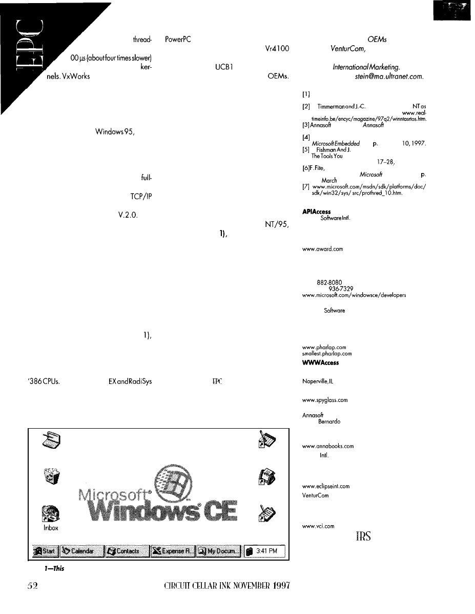
Microsoft
says
switch times are less than
1
than most real-timeembedded
and others use a
single process (single address space,
everyone resides in ring 0) system, making
context switches easy and fast.
Application-level drivers don’t require a
rigid driver format. Windows CE has a
registry system similar to
where
applications can be registered with the ker-
nel and receive interruptsdirectly, butthat’s
not the same as getting maximum through-
put via direct access to I/O registers.
As well, WinCE does not support a
function embedded Web server. There isn’t
enough RAM or ROM for complete
support and a Web server, but networking
is expected to be available in
The only announced Web server for the
product has no local file access, so it can’t
send HTML pages stored in the system. The
kernel needs to support in-memory files to
emulate a Web server’s function. (See Phar
tap’s “world’s smallest Web server.“)
The universal GUI-the Web browser-is
used in standard CE systems to communi-
cate as Web PCs with intelligent embedded
systems. Maybe Spyglass’s WWWAccess
will rescue Microsoft here, too.
However, because of the modular ar-
chitecture of Windows CE (see Figure
most of these missing functions can be
added or existing functions modified.
Windows CE has so much overhead
that Microsoft won’t support its kernel on
But, the Intel ‘386
EXPLR2 board are popular for developers.
By the end of September, we should
have seen support for generic ‘486s (if
virtual memory is supported), Pentium, and
chips. But, the
only chips
supported
real-time products to
and resellers
now are the Hitachi SH-3, NEC
for DEC,
and Phar lap Soft-
series, and Philips PR3 1500 (MIPS R3000
ware. He now heads his own company,
RISC core) and
1 00-not
exactly
Automata
You may
mainstream with embedded-system
reach Edward at
I T F I T S S O M E A P P L I C A T I O N S
Portable computer and automobile ap-
plications are Microsoft’s primary targets.
And while Microsoft also mentions some
veryembeddedapplications (e.g., tempera-
ture and robot controllers), this seems more
like a pipe dream than reality.
The WinCE kernel is a multiprocess OS,
and even if you develop for a single process,
the application and kernel are separate
processes, entailing much
higher
overhead
on system calls and I/O accesses.
If your product is not cost sensitive,
requires a graphical local display (espe-
cially one looking like Windows
as you see in Photo
or is sold as a portable
computer, using WinCE as an embedded
system makes sense. For the majority of
embedded computing products, however,
it’s either overkill or it won’t perform real-
time tasks with any determinism.
I believe the best outcome of Microsoft’s
entry of Windows CE in the embedded
space will be the tools developed for the
32-bit ‘x86 market.
Visual Basic and Visual C++ support in
multiplechip platforms, improvementofthe
Win32 API, and the promotion of a stan-
dard API (Win32 API) for embedded sys-
tems will help solidify that sector of the
embedded computing market using 32-bit
‘x86 platforms.
Edward Steinfeld
over 25 years’ experi-
ence in real-time and embedded comput-
ing. He has marketed embedded and
R E F E R E N C E S
Microsoft-sponsored Embedded PC Solutions Semi-
nar Series, Boston, MA, June 24, 1997.
M.
Monfret, “Windows
Real-Time OS?” Real
Time Magazine,
Systems, The
Guide to
Systems
that Work, San Diego, CA, 1997.
T. Wong, “Enabling the Windows CE Tsunami,”
Rev., 13, March
N.
Richter, “The Windows CE SDK:
Need to Program the Hand-held PC,”
Microsoft Systems Journal,
April 1997.
Jr., “Windows CE: The New Choice for
Dedicated Systems,”
Embedded Rev.,
29,
10, 1997.
S O U R C E S
Award
777 E. Middlefield Rd.
Mountain View, CA 94043
(4 15) 9684433
Fax: (4 15) 526-2392
Windows CE
Microsoft Corp.
One Microsoft Way
Redmond, WA 98052
(206)
Fax: (206)
Real-time ETS Kernel
Phor Lap
60 Aberdeen Ave.
Cambridge, MA 02138
(617) 661-1510
Fax: (617) 876-2972
BBS: (617) 661-l 009
Spyglass, Inc.
1240 E. Diehl Rd.
6 0 5 6 3
(630) 505-l 010
Fox: (630) 505.4944
Windows CE tools and license
Systems
11838
Plaza Ct.. Ste. 3 13
San Diego, CA 92128
(6 19) 673-0870
Fax: (619) 673-l 432
Mu
Handheld
Calendar
PC
Recycle Bin
Contacts
Tasks
photo
splash screen of a Windows CE system shows you the available applications.
Eclipse
381 E. Evelyn Ave.
Mountain View, CA 94041
(415) 691-6555
Fax: (415) 428-0292
2 15 First St.
Cambridge, MA 02 142
(617) 661.1230
Fax: (617) 577-l 605
413 Very Useful
4 1 4 M o d e r a t e l y U s e f u l
4 15 Not Useful
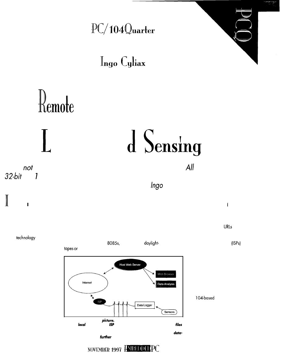
Internet Data
ogging an
Why build
remote PC/ 7 04 Internet-based data loggers?
you need is one
PC/ 04 CPU, a modem, an RTOS, application code,
and
some integration.
After looking at what benefits this brings the market,
shows how easily it’s done.
n college, worked as a part-time pro-
grammer for an electric-meter company.
One of the projects was a translation system
that converted data retrieved via modem
from a remote electric meter into billing and
usage reports.
Of course, our competitor wouldn’t di-
vulge their protocol specs. We had to obtain
(don’t ask) a competitor’s unit and reverse
engineer the protocol (finding the CRC poly-
nomial was the hardest).
The
was
exciting at the time.
Before, utility companies hired meter per-
sonnel to read and swap magnetic
memory modules containing the
details needed for the reports.
Handling such tasks remotely via
the phone line was particularly
appealing to utility companies
operating in the north (brrr...).
The system
finally
worked with both units.
The experience was good, since I learned
much about
modems, and
saving time-zone calculations.
A lot has happened since then. gradu-
ated, got married, had children, even lost
some hair. But, more interesting to you is
that the Internet exploded onto the scene.
Almost everywhere, you see
and
E-mail addresses advertised. This sudden
popularity has one important infrastructure
impact. Internet service providers
have a point of presence (POP) in almost
every calling zone.
Our translation system had
to communicate with two meter
styles-our remote metering
product and the competitors’.
Utilities rarely buy everything
from onevendor, and since there
were no standards for exchange
of metering data, we had to
implement two different proto-
cols to talk to the meters.
Figure I-Here’s the big
The data logger uses a telephone line to
dial up a
ISP. Since the
is connected to the Internet, data and
are sent via the Internet to a Web server, which can be anywhere on the
Internet. The data can be retrieved with a standard Web browser or
analysis software for
processing.
This new situation gives rise
to some interesting possibili-
ties. In particular,
why
not build
remote PC/l 04 Internet-based
data loggers?
I can embed the necessary
drivers and software in a
PC/
data logger so
it dials up an ISP, connects to
the Internet, and dumps data
on an Internet server. It’s what
the Internet does best-trans-
ferring information regardless
of the geography or content.
Figure 1 shows the big picture.
5 3
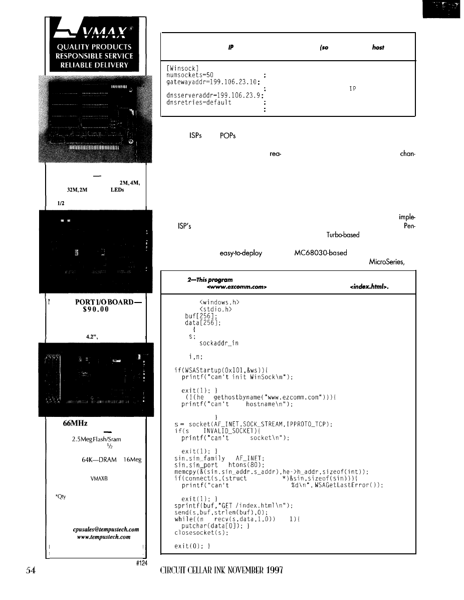
ENHANCED SOLID STATE
DRIVE
$89.00
5
Flavors: 2 or 3 Drives,
with Post
Either Drive Boots, FFS included
Card, XT Height, Customs too
MULTI
.
4 Serial Ports, 2 Bi-Parallel Ports,
2 Drive IDE, 2 Floppy Interface,
16 Bit Standard, 8 Bit Adaptable,
Low Profile
Full Cable Set
486
SINGLE CARD
COMPUTER
$335”
Up to
drive
Compact-XT height card size
Industry Standard
PC-1 04
port
L2 cache to
to
Dual IDE/Floppy connectors
All Tempustech
products are
PC Bus Compatible. Made in the
U.S.A., 30 Day Money
Back Guarantee
1,
Qty breaks start at 5
pieces.
TEMPUSTECH, INC.
TEL: (800) 634-0701
FAX: (941) 643-4981
E-Mail:
I-Net:
Fax for
fast response!
295
Airport Road
Naples, FL 34104
listing I--This is a configuration file for a protocol stack module. The most critical
information in it is the addresses for the name server
we can look up
names)
ond the default gateway.
Number of active TCP sockets
G a t e w a y I P a d d r e s s
bootp=no
Use BOOTP protocol for addresses
DNS server IP address
Number of DNS retries
d n s r e t r y w a i t = d e f a u l t
W ait time for DNS retry
WHAT FOR?
Since
have
almost every-
where, access is a just local call away. Sure,
there’s a monthly fee, but it’s usually
sonableand inmanycasesoffersunlimited
access. You can even share one account
among many data loggers.
Such opportunity, ofcourse, frees us from
maintaining our own central modem pool.
We pay the ISP to do it at a fraction of the
cost, since we’re only using a small chunk
of the
bandwidth to the Internet. After
all, we’re interested in the infrastructure.
The Internet is very robust. The military
designed it to be an
robust
technology. And even more amazing, it still
works when many different vendors with
their own (sometimes broken) implementa-
tions participate.
Even now that the communication
nels for the backbones are hopelessly satu-
rated, the Internet still functions-slowly, but
it doesn’t just crash all the time. Since my
application doesn’t require interactive re-
sponse times, even these slowdowns due to
congestion don’t bother me.
The Internet
is
also technology
and
mentation independent. When the next
tium MMX+
motherboardscome
out, they’ll be able to communicate with my
workstation (see my
“MC68030 Workstation”
INK
Listing
illustrates how to use the socket
API. If opens a connection to my
Web server at
and retrieves the index page
#include
#include
char
char
main0
int
struct
sin;
struct hostent *he;
int
WSADATA ws;
WSACleanupO;
if
=
get
WSACleanupO;
exit(l);
==
open
WSACleanupO;
=
=
sockaddr
open connection
WSACleanupO;
=
==
WSACleanupO;
IF YOU DO
Listing
the configumtion file for the Web upload/download plug-in.
the
control and configuration files look like Windows
files.
[connection]
host=www.weathercentral.com
Name of host Web server
Call host every 6 h
retry=3
Try up to 3 times to make a connection
Wait 10 min. between each retry
controlfile=/control/truro_ma/control.ini
Name of control file
for Truro. MA weather station
and 88). All this makes me wonder
what the oldest Internet node out there is.
Send me E-mail if you know.
By basing data loggers on
cards, it’s possible to build someverysmall
and robust systems. Many PC/l 04 cards
are available in extended temperature
ranges. Also, with solid state disks
available on most PC/l 04 CPU modules,
mechanical disk drives can be eliminated.
And since
systems are smaller
and lighter,
they
can
go places desktop
based systems can’t.
Many applications can take advantage
of this scheme. Seismological sensor net-
works, for example, can run on small
based embedded systems. With a GPS or
WWV receiver (for accurate time), seis-
mometer, and modem, the logger can log
time-correlated sensor data to the SSD and
dial up when there’s an event.
Since they can be so small, remote sen-
sors can live anywhere. They can also
share existing telephone lines with other
devices (or people). No land line available?
No problem, call an ISP via a cell-phone.
The amateur seismology Web page
(see References) has information on build-
ing and interfacing a seismometer to a PC
as well as on time references (see “Video
Fundamentals,”
77).
A remote medical monitor at the home
of a person with a history of medical
conditions is another possibility. Awireless
sensor could dial up and dump data regu-
larly, enabling medical professionals to
monitor how the individual responds to
treatment.
Listing 4-This PPP
file specifies the phone number to dial and the account
Port modem is connected to
irq=auto
IRQ
port is using or auto
Baud rate or auto
If 16550 chip present. enable it?
serinitconnect=yes
Initiate connection
modempresent=yes
Is modem present?
IP address of remote Web server
mask for IP address
Phone number or blank (for direct connect)
username=wcentral
User name for logon
password=genesis
Password for logon
sescriptfile=a:\config\sescript.ini
Path to send/expect script
or none
[handshaking]
CTS=yes
DSR=no
DTR=no
Hardware handshaking options
Either yes or no
is a sample chat script used log in an ISP.
expectO="CLIENTSERV"
YOU NEED
I
ELECTRONIC
EXTENDERS
Electronic PCI
Extender
PCI Mini
l
Insert/Remove Cards With PC Power On!
l
Save Time Testing And Developing Cards
l
Save Wear On Your PC From Rebooting
l
Adjustable Overcurrent Sensing Circuitry
l
NO Fuses, All Electronic For Reliability
l
Single Switch Operation W/Auto RESET
l
Optional Software Control Of All Features
l
Breadboard Area For Custom Circuitry
Passive MC32 Extender
Passive ISA Extender
NOVEMBER 1997
55
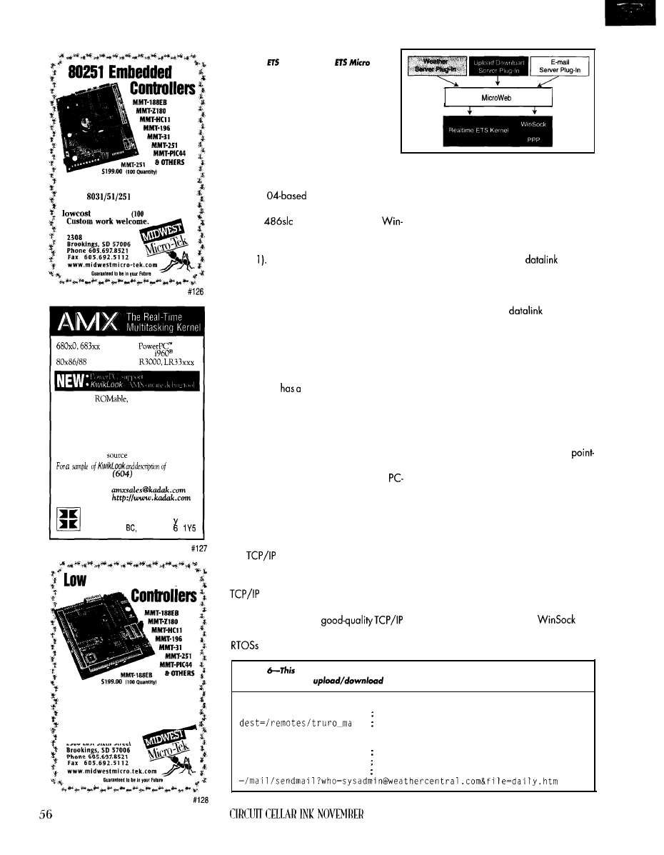
Midwest Micro-Tek is proud to offer
its newest line of controllers based
on the
architecture.
The 8031 comes in at a surprisingly
of $89.00
quantity).
MIDWEST MICRO-TEK
East Sixth Street
family
80386 protected mode
family
real mode
l
Compact,
fast interrupt response
l
Preemptive, priority based task scheduler
l
Mailbox, semaphore, resource, event, list,
buffer and memory managers
l
Configuration Builder utility
l
Comprehensive documentation
l
No royalties,
code included
AMX,
Phone:
734-2796
F a x : ( 6 0 4 ) 7 3 4 - 8 1 1 4
E-mail:
W e b :
KADAK Products Ltd.
206 1847
West Broadwa
Vancouver,
Canada V J
Cost Embedded
If you’re interested in getting the
most out of your project, put the
most into it. Call or
Fax us for corn-
plete data sheets and CPU options.
C u s t o m w o r k w e l c o m e .
MIDWEST MICRO-TEK
2308 East Sixth Street
Figure 2-At the core of this system is the
Realtime
Kernel and the
Web
Server, which are extended and customized
for a specific application using plug-ins.
Another application is weather monitor-
ing. Phar tap’s “world’s smallest Web server”
is a PC/l
weather station on the
Internet. It uses a Real Time Devices-based
PC/l 04
CPU module with a
Systems PC/l 04 NE2000 Ethernet card to
implement
a
self-contained Internet host (see
Photo Point your browser here, and you
can read the current temperature, humidity,
and barometric pressure as well as down-
load weather history for the day.
With this technology, it’s quite easy to
imagine a PC/l 04-based remote weather
station that collects data offline. It would
connect to the Internet using the serial port
on the CPU module and upload weather
data to a server.
Phar tap
complete toolsuite imple-
menting this scheme. It’s called a “remote
web server,” instead of a “host web server”
that’s permanently connected to the Internet.
HOW IS IT DONE?
To embed remote Internet, take a 32-bit
PC/ 104 CPU (‘386 or better) with a
compatible COM port and external modem
or PC/l 04 modem card. Add a PC-based
RTOS with protocol stack and PPP driver,
write some application code, and integrate.
The protocol stack-sometimes called
the
module or plug-in-is a collec-
tion of routines and drivers implementing
the IP suite. It used to be exotic to have a
implementation that wasn’t part of
a larger OS (e.g., Unix or VMS). But with
the Internet explosion,
implementations usually come with many
and other operating systems.
ETS
Sewer
At the bottom of the protocol stack is the
interface to the network device drivers. Net-
work interfaces-like Ethernet cards or se-
rial ports-send and receive packets.
For a remote Internet device, I only care
about the PPP network interface, which
sends packets over a serial line. PPP was
developed as a standard
protocol
between routers over high-speed synchro-
nous serial lines, but it has been adapted to
work over asynchronous serial lines and
modems. PPP is the
protocol of
choice for Internet modem connections.
PPP drivers, which communicate over
dial-up modem networks, normally imple-
ment a scripting language. This language
writes “chat” programs, which tell thedriver
where to call, how to log in to the ISP, and
how to set up a PPP connection.
Once the modem connects and the chat
script logs in to the ISP, the PPP protocol
takes over and negotiates parameters like
the pair of IP addresses to use in this
to-point link. Once PPP is happy with its
negotiations, the PPP network interface is
marked as “UP,” and the protocol stack can
then send and receive IP packets via PPP.
To function fully, the protocol stack needs
two parameters-the default gateway ad-
dress and the name server address. These
are normally derived from a configuration
file [see Listing 1).
Most protocol modules implement the
Berkeley socket library API on the applica-
tion side. Under Windows, the socket inter-
face exists in the form of the
API.
Having a standard network API is nice,
since it lets me design and test network
Listing
control file was downloaded from a Web sewer. Much
like a batch file, it
specifies what the
module has to transfer.
[directories]
src=/weather
Source directory on remote Web server
Destination directory on host Web server
[upload]
latest.htm=current.htm
Current weather readings
daily.htm=daily.htm
Daily weather readings in HTML format
daily.txt=daily.txt
Daily weather readings in ASCII format
1997
code on my development machine before
targeting
the
code
in an embedded system.
Listing 2 shows how the socket API works.
The
library gets initialized
can go on to the real socket code.
then allocate a communication socket,
socket
The
arguments
indicate the kind of protocol
want and the type of connection.
I’m only
concerned
with two connection
types-SOCK_DGRAMandSOCK_STREAM.
A stream-based socket permits a reliable
end-to-end communication path, whereas
datagrams are packet oriented (with lower
overhead) but inherently unreliable.
Once I have a socket, I need the
address and port number of the host and
service want to connect to. Here, look up
using
and port number 80, which is the Web
server (HTTP protocol).
The program uses send
which copies
establishestheconnection.
canfailformanyreasons,and
canfindoutwhy.
Once the session is established, I can
send and receive data. Many Internet ap-
plication protocols (e.g.,
and ftp) are
implemented via a stream-type connection.
I use HTTP (i.e., the protocol for the WWW)
to get a page from my Web server.
To read a page on a Web server, send
GET
/index. html, which tells the Web
server to open and send
i
ndex. html.
the data from buffer memory and sends it to
the remote socket. receive data with the
call.
Stream connections are reliable-no
need for checksum or CRC error detection.
It’s all handled at lower levels of the proto-
cols. Whateveryousendvia
send
comes
out the other end with the
call as
long as this virtual data circuit persists.
Once the data is read from the server,
returns 0, indicating that there’s
nothing else to read and the server breaks
the connection. I then stop receiving and
and
to release any
sources the
module used.
This is how you write an application to
communicate with other Internet hosts. In
fact, all standard Internet protocols (e.g.,
WWW, telnet, ftp, and E-mail) can be
implemented with these simple but power-
ful primitives.
USE THE WEB, LUKE
The most widely used Internet applica-
tion protocol today is HTTP. Every ISP has
a Web server, almost every business on the
Internet has a Web site, and all desktop
systems come with at least one browser, not
counting commercial and public-domain
browsers for current and older
a host Web server from my data logger.
Web servers are normally information
sources (i.e., the information is retrieved
from the server). But, I want to put data on
Listing
simple plug-in reports the current date and time in a remote Web sewer.
date/time plug-in adapted from
which comes with Phar
Lap's
Server
date_htm-Main HTML page for a date/time plug-in
BOOL _cdecl
char
Open empty HTML
return FALSE;
Start with HTML header
Time Page\"");
Date and Time\"");
Grab and convert current date and time
html
date:
buff);
time:
buff);
return
Done-return HTML page
. 7 ISA slots
The
motherboard
combines quality and
affordability with an industrial
design to meet your needs.
Seven full length ISA slots
ensure expandability for the
cards that you use.
Our engineering staff will
gladly discuss custom
motherboard designs. FCC
UL certified systems are
also available.
l
Six full length 16-bit ISA, One
shared
slot
l
Intel, AMD SGS-Thomson
486 CPU support
l
VIA
l
Up to
256KB cache
30
5 7
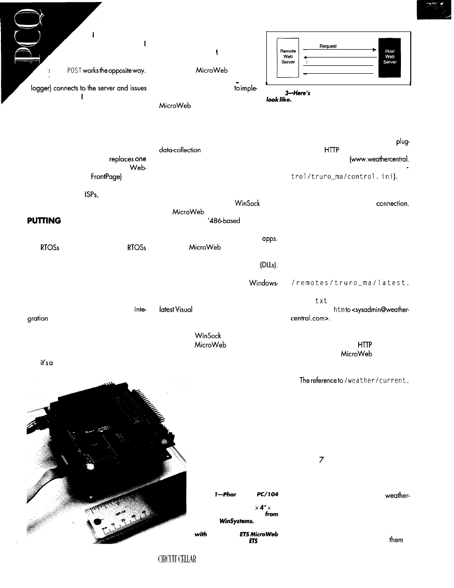
can do this via the
HTTP POST method.
showed you how to use
GET
to retrieve pages from a Web
server.
The client (here, the remote data
POST with the data want to send as input.
It’s the same command used to submit forms
from Web pages (i.e., when you sign a
guest book or order something via the
Internet). POST is often implemented with a
server’s CGI script, which is a special
batch file that processes received data.
Or, I could use PUT, which
Web page with another. Several
authoring tools (e.g.,
use it to
upload Web pages. However, PUT is not
implemented by all
since it is harder
to administrate than POST.
I T T O G E T H E R
One nice feature of PC-based embed-
ded systems is the availability of off-the
shelf
and components. These
are typically lean and mean.
Most optimization has been taken care
of, since the architecture is known in ad-
vance. And since many of the hardware
devices (e.g., serial ports and Ethernet
cards) are standard, the same driver works
with other vendor’s hardware. System
is a breeze.
An RTOS that’s particularly good for this
application is Phar lap’s Realtime ETS Ker-
nel. As the core component of Phar Lap’s
TNT Embedded Toolsuite development sys-
tem,
deterministic, thread-based, hard
real-time kernel supporting a Phar
Lap-defined subset of the Win32 API.
It has everything need to build
a remote Internet data logger, includ-
ing the ETS
Server-a
collection of libraries and plug-ins
control
Control file
Send current weather reading
Send daily summary
l
linking with my application
ment a remote Web server. The ETS
Figure
what a sample upload session might
Server runs under the
Realtime ETS Kernel on the target system.
With this package, all that’s
left is
to buy
a PC/l 04 CPU module, configure the soft-
ware, and write a module to perform my
application. I had a demo
system running in less than a day. Figure 2
gives you an idea of how it fits together.
This system has a small memory foot-
print-perfect for PC/l 04 CPU modules.
The Realtime ETS Kernel is
only
-32 Kb, and
a complete system with the
library
and
Server fit in less than 1 Mb
of memory. Most
PC/l 04 mod-
ules come with 4 Mb of DRAM-plenty of
room for sophisticated Internet-based
The ETS
Server is expanded
by using plug-ins, which are standard Win-
dows-based dynamic load libraries
This makes the development environment
particularly nice, since standard
based C/C++ compilers can be used.
But, don’t tear the shrink wrap on the
C++ or Borland C++ quite yet.
You might not get to write code.
The Realtime ETS Kernel comes with a
PPP driver,
API library, E-mail
plug-in, ETS
Server, and Web
based upload/download plug-in. I already
discussed the PPP and API, so let’s look at
the upload/download plug-in.
This plug-in is a DLL that
transfers Web pages between
Web servers. It might sound
odd, but let’s look at how this
works for the data logger.
Photo
Lap’s
based “smallest Web server”
fits in less than a 4”
2”
footprint using modules
RTD and
It imple-
ments a complete Internet host
Phar Lap’s
Sower and Realtime
Kernel.
As Listing 3 shows, the plug-in has a
configuration file on the data logger that
controls when to wake up and what to do.
At
wake up, the upload/download
in opens a
connection to the host
Web server specified
corn) and downloads a control file
(/con
The
PPP driver then wakes up and consults its
configuration file to find out where it needs to
dial up to establish an Internet
Listing 4 has a sample of the PPP con-
figuration file, and Listing 5 shows the chat
script used for this connection. Once the
PPP module connects, the upload/download
plug-in downloads the control file.
In the sample control file in Listing 6, the
plug-in uploads the local file /weather/
current. htm to the host Web server as
htm. It also sends daily.htm and
da i 1 y .
. After all that’s done, it E-mails
the
file
da i 1
y .
Figure 3 shows the transac-
tions of a typical upload session.
Notably, the local file references in the
control scripts are really
resources on
the data logger’s
Server. These
resources can refer to a method in a DLL or
a file in the file system.
h tm
in the example refers to a method that
generates HTML pages dynamically with
Phar Lap’s HTML-on-the-fly library. Once all
the data is transferred, the PPP plug-in times
out and hangs up the modem.
Pretty slick! All that’s left is coming up
with a method that presents the data to be
uploaded as a dynamic HTML page.
Listing shows a simple method that
reads the current date and time and for-
mats the output as a HTML document. Of
course, if I wanted to build a remoteweather
station, I could just use Phar Lap’s
station plug-in and be done with it.
What else can I do? By adding defini-
tions in a [download] section, I can
instruct the remote Web server to grab files
from the host Web server and store
in
58
INK NOVEMBER 1997
RAM or on the SSD. This mechanism can
update configuration files and software on
the data logger remotely. Once the data
transfers to the host Web server, standard
Web browsers or application-specific
analysis software retrieve and process it.
SECURITY CONCERNS
Now, I
have a way for a remote data
logger to transfer files to and from the
Internet
on demand using standard Internet
protocols. But, what about security?
There are three things to be concerned
about. An intruder may try to break into the
data logger from the network and wreak
havoc, someone can try to read or alter the
data on the host Web server, and data can
be intercepted while traversing the Internet.
The first issue is pretty easy to address.
The data logger is only online during short
periods of time. While online, you can
control what services are available to the
Internet by the type of plug-ins you have
installed and Phar Lap’s security plug-in,
which restricts access to the remote Web
server by specific Internet addresses.
Transfers to and from the remote Web
server are controlled via configuration files.
With this mechanism, can control which
data transfers to which host Web server.
The host Web server usually implements
several types of security methods by imple-
menting authentication (i.e., accounts and
passwords) and access lists that restrictwhich
host accesses certain areas on the host Web
server. Also, since this host server usually
resides with some ISP and is shared by pay-
ing subscribers, the ISP operator should take
a keen interest in practicing good security.
To prevent someone from listening to our
traffic on the Internet, we can use standard
encryption methods (e.g., RSA) already in
placeforsending sensitivedata (e.g.,
card information) over the Internet. Using
RSA, the remote Web server requests a
public
key
for
a resource from the host Web
server. This key then encrypts the message.
While the message is encrypted using a
public key, it can only be decrypted with
the host server’s private key, which is kept
secret. The message is unintelligible while
traversing the Internet.
You can also use secret key algorithms
like DES to encode messages. In this system,
the same key encodes and decodes, making
key management and distribution harder.
While none of these methods are 100%
safe, they protect us from the semi-serious
bad guy. Ultimately, it comes down to how
sensitive your data is and how hard you
want to make it for someone to get it.
ON THE ‘NET
A desktop system used to build
ready applications. With Phar Lap’s tool kit,
I can build Internet-ready embedded devices
with a
PC/l 04 module
and
a modem.
Now, I just have to figure out how to filter
the data-logger messages from the
ending volume of get-rich-quick scams. Too
bad off-the-shelf embedded Internet tech-
nology didn’t exist 15 years ago. I’d prob-
ably have more hair now and be a better
Web programmer, too.
is a research engineer in
Analog
and Robotics lab and teaches
hardware design in the computer-science
department at
University. He a/so
does software and hardware development
with Derivation Systems, a San Diego-based
formal-synthesis company. You may reach
at
REFERENCES
Text
Phar
Lap Software,
Technologies Guide
book,
Cambridge, MA, 1996.
SOURCES
486SU PC/ 104
CPU Modules
Real Time Devices USA
200 Innovation Blvd.
State College, PA 16804
(8 14) 234.8087
Fax: 14)
18
modules (CPU, Ethernet, modem)
715 Stadium Dr.
Arlington, Texas 7601 1
(8 17) 274.7553
Fox: (817) 548.1358
RTOS, Web server, stock
Phar Lop Software
60 Aberdeen Ave.
Combdridge, MA 02 138
(617)
Fox: (617) 876.2972
4 16
Useful
417 Moderately Useful
418 Not Useful
1997
59
Megatel Offers a Wide Range of Embedded PC Architecture
‘Embedded
for the
On-Board Features such as:
l
8088 or
Processors
l
Local Bus Super VGA supporting LCD Panels
l
Up to
DRAM
l
Ethernet Local Area Network
l
On-board programmable
l
Low Power Consumption
l
Operation
volts only (typical)
l
2 IBM compatible RS-232C Serial Ports
l
general purpose Parallel
Port
l
Only 4” 4” form factor
l
ISA or
Bus compatible options
For
information
Toll Free:
1'669'762.5572 416.245'2953
fax:
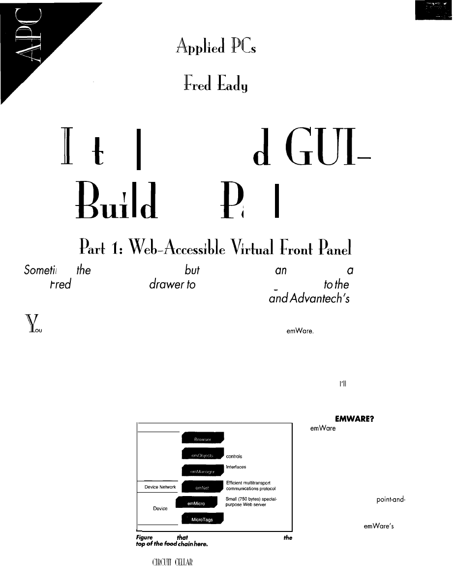
n
er
aces
an
fng
ac
k
ages
nes
product is
perfect,
you
can’t
make
interface
for
reasonable
price.
checks
his
fool
see if
anything
can come fescue. He
Finds em
Wure’s
embedded application
enabler
KM-4862.
just designed the ultimate electronic
device. Every ounce of functionality was
squeezed in. The board layout is tight, the
component count low. It can stand alone in
a closet until redemption day.
You thought of everything, every contin-
gency. If marketing didn‘t think of it, you
did. And, it’s all in the current firmware.
It’s perfect-but the user interface is
going to cost more than the product!
Now what? No engineering bonus.
No innovation award.
What
you saved
in hardware design will be spent on
the interface. You need a friend (and
a cheap front panel) about now, huh?
The good news is that we can call
on some friends-old and new-to
help us out of this jam.
The Internet has become so popular,
it’s a household word. And, riding its
coattails is the Web browser, taking a
place as the world’s most familiar GUI.
Web-oriented devices and software
Visual Basic 5 has a specialized integrated
Web browser. Every OS and software de-
velopment-tool package from QNX to Phar
lap ships with Web-capable functionality.
Today’s embedded hardware can sup-
port any Web-oriented software package.
Most anything can be done on the Web
somehow, some way.
So, let’s put our friends to the test, stir in
some Java, and sweeten it with a bit of
Provides widely available
user interface
Client
Defines high-level device
between browser
and device
(Embedded)
Small packets of information
which define device controls
The mix yields a feature-rich vir-
tual user interface that can be accessed via
a serial interface or Web browser.
Add a PCM-4862 embedded platform
from Advantech, and whop! Instant Web
accessible virtual front panel on the cheap.
This time around,
introduce you to the
tools we’ll use to design and build our own
embedded virtual front panel.
are everywhere. Microsoft’s Visual
Studio is fully Web compliant. Even
I-Notice
the embedded-PC application is at
6 0
INK NOVEMBER 1997
W H A T ’ S
brings a unique embed-
ded-application enabler to the Internet
world. Embedded Micro Interface
Technology (EMIT) lets users control,
configure, and manage devices not
previously connected to the Web us-
ing available Web browsers.
W eb browsers are in everyone’s
hands these days. Their
click interfaces are easy to use and
provide a perfect GUI.
One advantage to
us-
ing a Web browser is that little-to-no
new software-development effort
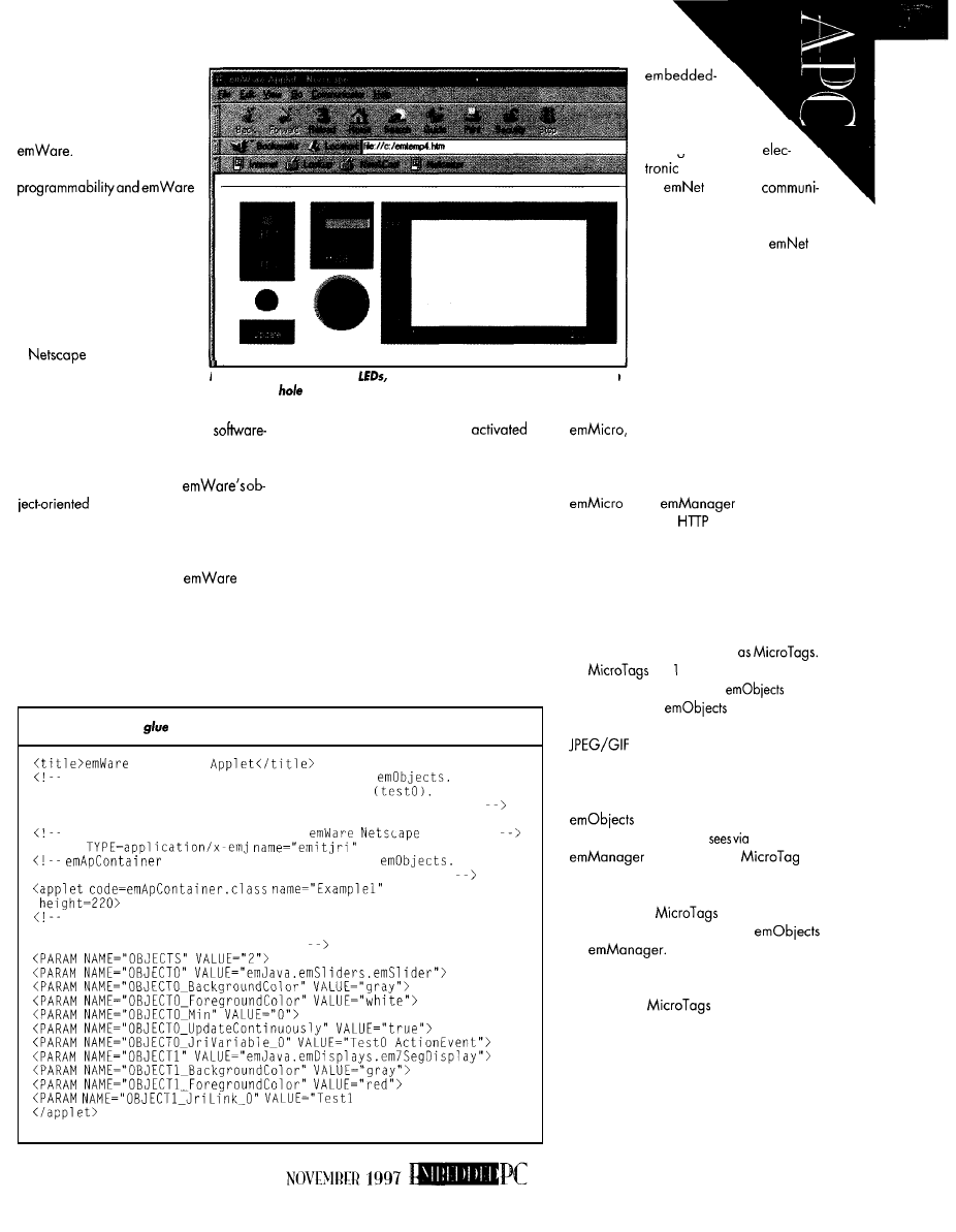
needs to be put into the embed-
ded-PC interface. Anyone who
can point and click can ma-
nipulate remote devices with
With standard Web-browser
controls, you can present an
almost identical virtual image
of the remote device--complete
with interactive controls and
functions the user can manipu-
late via the browser interface.
The EMIT Software Devel-
opment Kit (SDK) does this via
a
plug-in. The inter-
action with the Web-browser
software is the real power be-
hind EMIT.
Photo l-Knobs, switches,
graphs-all remotely controlled. You can
trash those
punches and socket wrenches you had to use before to
fabricate your front panels.
The remote device could be a
configurable black box without external but-
tons, indicators, switches, orcontrols. Using
standard browser tools and
interface logic, the designer
can fabricate a virtual front panel simulating
the black box’s internal electronic controls.
Since much of the standard interface
coding can be eliminated,
can
cut production costs by a factor of 100.
That remote black box is now less costly to
manufacture, since no physical user-inter-
face components are required.
Futurefunctionalitywithin the black box’s
firmware and hardware can be designed
in at initial manufacture and
or
deactivated by changing the black box’s
“look” to the user at the interface.
And, the black box is easier and less
costly to maintain. The Internet connection
provides a reliable and cost-effective way to
offer remote firmware and software support.
The technician’s virtual view can be
configured differently from the user’s view
to aid in remote diagnostics. The black box
view can even be customized for each user.
EMIT ARCHITECTURE
EMIT operates as a “fat client, skinny
server” system with the client being the
listing l-Here’s the
behind that cheap LED array.
Example 1
U s e s t h e J a v a f l o w l a y o u t f o r p l a c i n g t w o
O b j e c t 0
i s a s l i d e r c o n t r o l l i n g a n e m b e d d e d v a r i a b l e
O b j e c t 1 i s
a T - s e g m e n t d i s p l a y o f r e s u l t s o f s e t t i n g e m b e d d e d v a r i a b l e
<hr>
EMBED TYPE tag needed to activate
plug-in
<EMBED
HIDDEN>
is the Container Applet for
Width
and height must be specified with the code declaration.
width=300
Specifying the number of objects reduces the number of objects
the applet will search for. Default is 256. Make sure the largest
object number is less than objects.
Value">
<hr>
system-based
Web browser and
the server being an
intelliaent remote
device.
is a serial
cations protocol that provides
network connectivity between
the client and server.
is
transport-layer independent
and supports all standard
point-to-point, Internet, and
lntranet protocols. Its ability to
interface to any Web browser
and its lack of concern for
protocol assure platform inde-
pendence.
The remote-server engine,
consumes as little as 30 bytes of
RAM and 750 bytes of ROM. This configu-
ration is minimal, so most applications end
up with a little over 1 KB of ROM. Together,
and
form a true
distributed micro
server with exten-
sions supporting the unique requirements
of electronic devices.
Minimal required resources aren’t the
only skimpy attributes of the micro Web
server. The conversations between the em-
bedded PC and the server are highly con-
densed data packets known
are byte or more in size and
correspond one-to-onewith
at the
embedded PC.
is a small library
of preprogrammed functions consisting of
graphics or Java applets. They
give the browser the high-level controls neces-
sary to interface with the remote device.
The actual interface is assembled with
that translate to the virtual con-
trols and buttons the user
the browser.
expands each
us-
ing a process called dynamic expansion.
Once received and processed, each
HTML page of
is displaced with
corresponding embedded-PC
by
They are then converted
into information presented to the user via
the embedded-PC browser.
Using tiny
eliminates hoving
toshiplargechunksofdatafrom theserver,
reducing link bandwidth requirements and
increasing user-display speed. The EMIT
architecture is illustrated in Figure 1.
CREATING THE USER INTERFACE
All EMIT components work together to
61
electronic device. Us-
ers work directly with the
Web browser at
embed-
ded PC.
Via the browser, the user re-
quests the interface for the device they
need to work with. The browser sends the
request to
which converts or
translates the high-level user request and
sends it to
at the device.
requests an HTML page
containing
which is how the
interface is stored within the device. All
for device controls are embed-
ded within an HTML page, so the entire
device interface is contained in one HTML
page. When
receives the request,
it serves the page back to
P R O C E S S I N G U S E R R E Q U E S T S
Say a user wants a switch toggled at the
remote device. Once the request is initiated,
the browser invokes
and a
request is sent to
at the device.
Receiving the request causes the control-
ler or processor to perform the request.
Toggling the switch changes the informa-
tion in the device and the
The embedded-PC view must be up-
dated to show the new switch condition.
updates the variables in the
and sends them to the embed-
ded PC.
receives the updated
HTML page and displays the results of the
request on the embedded browser screen.
E M I T T O W O R K
First, plan the interface. When users
connect to the device, the Web browser
accesses the device via HTML pages. The
pages have an applet tag, identifying a
Java program to load and place onscreen.
Cont. a i ner applet
grammed and available to the Web browser
photo
really cheap LED array!
after
is installed. The HTML files
control the look and feel of the interface.
Files for the high-level interface may be
installed on the device’s processor or at the
embedded PC. Installing the files on the
embedded PC saves space but requires
device-specific files to be loaded before
connecting to the device.
The only con with loading the interface
on the device is that extra space is needed
in the device ROM. Loading the interface
on
client software on their embedded PC to
use the device without delay.
Once you decide where the interface
will reside, it’s time to lay out the screen.
provides many ready-to-roll
switches, gauges,
and knobs, or you
can design custom controls. Photo 1 shows
some of the built-in
controls.
Once the layout is pinned down, the
next step is to code the high-level interface.
You need to create an HTML page that:
l
activates the
plug-in
l
runs the
Java
photo
core of the
is solid.
much or as
as you
need off this
vates EMITJRI, whidh extends
with functionality
tailored to the needs of the
embedded device.
can hang as
Next, the HTML page must
applet creates
dynamically, sets
properties, links
to
events, controls object layout, and links
events and properties to the
device controller variables.
The HTML page defines and sets
definitions. This process is set
forth in Listing 1. Photo 2 shows the result-
ing interface.
IT ON THE TABLE
With the high-level interface complete,
programming theembedded device to work
with
is a simple matter of integrat-
ing
with the application software
controlling the interface.
This task is accomplished with data
tables.
uses data tables (see List-
ing 2) so
and the device applica-
tion program can pass data variables
between themselves.
Next, you must set up the Capabilities
Document, Internal Variable Table, and
External Variable Table.
The Capabilities Document is a table of
information telling
what ca-
pabilities the controller or processor sup-
ports, so itcancommunicateappropriately.
The internal Variable Table is used to
find the internal memory addresses where
variable information is stored.
The External Variable Table tells the
high-level interface about the device’s vari-
ables. It ties the high-level interface at the
embedded PC to the low-level controller
variables at the device.
You then incorporate the
func-
tionality into the device’s application code
by calling the
initialization rou-
tine and performing any additional initial-
ization necessary. Standard
i n c 1 u d e
files
containing the
code let you per-
form this function.
After all variables and program func-
tions are tested, the interface is compiled,
compressed, and placed into the device for
final testing.
ADVANTECH’S PCM-4862
The fat-client concept implies that the
embedded PC is robust enough to run a
Web browser and
client software.
It further implies that a GUI-capable oper-
ating system is resident as well.
Advantech’s PCM-4862 All-in-One SBC
is a good choice for our virtual front panel.
The small-footprint
‘486
62
INK
1997
sor is complemented by the usual
Normally, we’d place the embedded
including
Ethernetcapability.
PC in the resourceprudent “remote” role.
Mine comes with 16 MB of RAM and
But, since the PCM-4862 is more than
a
SSD. Count the I/O connectors
enough machine to handle the
in Photo 3 to get a good idea about the
1 .O SDK and
under Windows
PCM-4862’s capability.
95, it’s not a problem.
listing
not as complicated as it looks, but every byte has to be in its place.
Data Tables *
Capabilities
02
Byte 0, DO Packet Document Retrieval
specification,
Byte ordering
00, 07
Bytes 1 2, Max Packet Size
00
Byte 3. Protocol Level
01
Byte 4, Protocol Revision
00, 01
Bytes 5 6, Device ID
00, 05
Bytes 7 8, Product ID
00, 01
Bytes 9 10. Manufacturer ID
00, 110
Bytes 11 12,
Revision (1.1)
Byte 13, Tables Present:
DO Static Documents, Variable Table
D2 Dynamic Documents, Function Table, D4 Event Table
. . .
= Capabilities) 1
variable table retrieves variable address from host and
refers to variables according to where they appear in EMvartable.
Table contains actual address where these variables reside
Edit this table to include names of all your variables
ivartable
Knob
Red
Green
Mode
Button
0
holders for nonvolatile variables
0
holders for nonvolatile variables
0
holders for nonvolatile variables
0
holders for nonvolatile variables
**variable table sent in response to
request from host
10
;= of variables
0
BYTETYPE+READWRITE
TYPE byte for variable 1
TKNRESPONSE
TYPE byte for variable 2
0
BYTETYPE+READWRITE
TYPE byte for variable 3
0
BYTETYPE+READWRITE
TYPE byte for variable 4
0
BYTETYPE+READWRITE
TYPE byte for variable 5
0
BYTETYPE+READWRITE
TYPE byte for variable 6
NONVOLATILE
In nonvolatile storage
BYTETYPE+READWRITE
NONVOLATILE
In nonvolatile storage
BYTETYPE+READWRITE
NONVOLATILE+ARRAY
In nonvolatile storage
BYTETYPE+READWRITE
NONVOLATILE
In nonvolatile storage
BYTETYPE+READWRITE
Null terminated string for variable 0
Array of 200 values
=
1
NOVEMBER
Sets The Pace
In
Data Acquisition
Scan 16 Channels...
Any Sequence...
Any Gain...
DM6420
KHz Analog I/O Module
with Channel-Gain Table and FIFO
With Companion
133 MHz
PC/l 04
The
offers
versatile embedded
Our
PC/l
04
and
ISA Bus
Product Lines Feature
Intelligent DAS Cards With
Embedded PC and DSP,
Analog and Digital I/O, CPU,
Shared Memory, SVGA, PCMCIA,
CAN Bus and GPS Modules
Time Devices USA, Inc.
200
Innovation Boulevard
State College, PA
USA
l
RTD Scandinavia Oy
Helsinki, Finland
Fax: 358-9-346-4539
RTD is a founder of the
Consortium
6
WHILE WE’RE WAITING
Now,
the only server micro
supported is the 8051. hear
the nextversion will include other
processors, too. Although I’ve
turned the
of-the-link embedded-PC para-
digm around, who’s to say the
remotedevice running
couldn’t be an embedded PC?
Next month,
more
in-depth tour of
internals and how to embed
Photo
amazing. Turning the pot changes the LED’s
them whileassembling
intensity on the
screen. You can also do the same
with the virtual knob from Netscape.
virtual front panel on the
Advantech PCM-4862.
This
is limited to a
choose a processor, design the inter-
single serial interface through
face, and emulate it on an Advantech
only. Future releases will include
bedded PC. I hear a point-and-click design
ality for modem, proxy, and multiple inter-
interface will be included with the new
face ports as well as Internet Explorer
version of
I’ll show you that, too.
support, which is where the Ethernet inter-
If you want to bone
up
on
an
face will come in handy.
SDK is currently available that
In the next release, total
includes documentation and a demo board
tion will be available. Using the two
so you can put EMIT to work immediately.
4862 serial ports, we’ll design and test our
The reprogrammable SDK demo board
emWare/Advantech virtual front panel
shown in Photo 4 consists of an 805 1 micro
using
only
embedded PCM4862 hardware.
with supporting EEPROM,
switches,
and pots. A demonstration program lets
you remotely control all those goodies and
quickly get up to speed with
Fred Eady has over 20 years‘ experience
as a systems engineer. He has worked with
computers and communication systems
large and small, simple and complex. His
forte is embedded-systems
design
Fredmaybe
SOURCES
EMIT, SDK
1225 E. Fort Union Blvd., Ste. 220
UT
256-3883
Fax:
1) 256.9267
PCM-4862
All-in-One SBC
American Advantech Corp.
750 E.
Ave.
Sunnyvale, CA 94086
Fax:
4 19 Very Useful
420 Moderately Useful
42 1 Not Useful
board comes ready for
demanding
applications,
with 16 bit DSP capability,
and
Compatibility.
Debug and up
to one Megabyte of battery
Sacked RAM creates a robust
environment.
* 16 Programmable l/O lines
* 8 High Drive Digital Outputs
* 8 Channels of Fast 10 bit A/D
* Optional 8 Channel, 8 bit D/A
* Up to 2
Serial Ports
* Backlit capable LCD Interface
* Optional 16 Key, Keypad Interface
* 16 bit Timer/Counters with PWM Clock/Calendar
* 64K RAM EEPROM included plus Flash Capability
WORLD WIDE WEB:
6
4
INK
1997
DEPARTMENTS
From the Bench
Silicon Update
MC68030
Workstation
Cyliax
Cross-Development Environment
and Downloading
t
a
university,
it’s sometimes
easier to justify
ing money on hardware
than software. And besides, people in
computer-science departments tend to
pride themselves in their ability to roll
their own.
But, I didn’t fancy spending the next
five years writing and supporting yet
another C compiler. Instead, I opted to
look for freely available tools on the
‘Net.
Several C compilers and 68000
assemblers are out there, so in this
article, I discuss some of the packages I
used. Of course, still had plenty to do
to set up a suitable environment, so
I
wasn’t at all deprived of the experience
to roll my own.
In this final installment of the
MC68030 series, I start out with a look
at some software-development tools
and how network booting works. I also
discuss some applications that were
done on the MC68030 system de-
scribed in Parts 1 and 2. One of the
tools is a network application that
permits students to log in to a Unix
machine to edit and compile programs
and then download them for execution
and debugging.
COMPILERS AND ASSEMBLERS
The MC68030 comes from a long
line of 68000 chips that was first intro-
duced about 17 years ago. Naturally, a
large collection of software has
66
Issue 88
November 1997
Circuit Cellar INK@
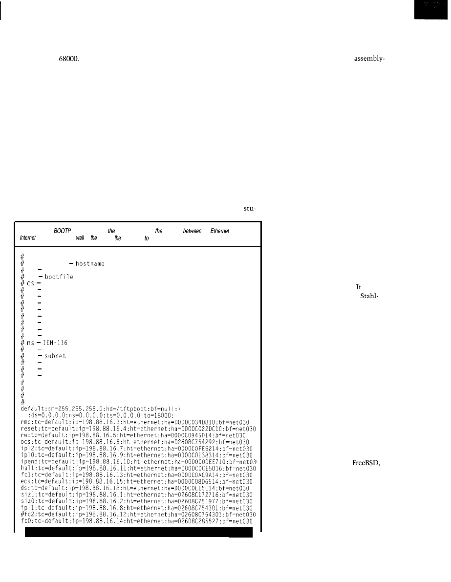
mulated over the years. There are
many assemblers, and almost all pro-
gramming languages have been imple-
mented on the
Originally, the computer-science
faculty at Indiana University intended
for students to program this system in
assembly language only. For this, I
chose asm68, which was written by
Paul McKee.
This assembler is a stand-alone
system that takes Motorola-format
assembly-language files and generates
a Motorola S-record hex file. It also
generates a traditional assembly listing
and a symbol table file.
asm68 comes in source-code form
and is fairly easy to compile for other
systems, since it doesn’t require many
services from the OS. I’ve built this
assembler under Minix and Unix, and
students also have built it under DOS
on their PCs at home. Being able to
run it under Unix lets students edit
their source files in the familiar pro-
gramming environment of our net-
work of Sun workstations.
While asm68 is very compact and
enables the students to explore archi-
tectural features of the 68030 system
in lab, it doesn’t allow multimodule
programs.
Multimodule programs are when
the student can use modules developed
in an earlier lab (e.g., their own key-
board driver) and link them into a
more sophisticated program. With
asm68, the student has to cut and
paste everything into one monolithic
file and assemble it.
Besides the limitation of single-file
modules, the instructors thought
Listing l--This
fable resides on server. If contains mapping
the
and
addresses as
as name of boot image download.
Legend:
first field
(should be full domain name)
hd home directory
bf
cookie servers
ds domain name servers
gw gateways
ha hardware address
ht hardware type
im impress servers
ip host IP address
lg log servers
lp LPR servers
name servers
rl resource location protocol servers
sm
mask
tc template host (points to similar host entry)
to time offset (seconds)
ts time servers
Be careful about including backslashes where they're needed. Weird
things can happen when a backslash is omitted where one is intended
dents would benefit from writing some
of the high-level functionality in C,
while maintaining exposure to the
hardware interface through
language modules. Once the low-level
modules were written, the students
would have more flexibility in writing
more complex programs.
By mixing C and assembly lan-
guage, students gain some insight in
how high-level language constructs are
implemented on a machine like the
MC68030.
GNU TO THE RESCUE
Luckily, since I was already using
the GNU-C environment to develop
the monitor for this system and other
applications, this was a no brainer.
I
could use the same development envi-
ronment being used to develop the
firmware for the system in the stu-
dents’ labs.
Well, that was easier said than
done. Let’s first take a look at GNU-C
(the compiler) and GNU-as (the assem-
bler) to write software for the stand-
alone software and operating system.
The GNU-C compiler has been
around for quite some time. was
originally written by Richard
man of the free-software foundation
(FSF). In fact GNU, which stands for
“GNU is Not Unix,” is a whole tool
suite of utilities that the FSF develops
and gives away free.
Other popular utilities besides
GNU-C are Emacs and Ghostscript.
Due to the open philosophy, many
people and organizations contribute to
these tools by porting them to new
environments, adding features and
functionality, as well as fixing bugs.
The current GNU-C supports too
many architectures to list here. It can
be used as a system compiler for a
particular architecture/operating sys-
tem and, in some cases, is even better
than the vendor-supplied compiler.
For example, Linux and
both freely available Unix-like operat-
ing systems, use GNU-C as the system
compiler. Also, many software pack-
ages can compile with GNU-C, which
makes it sort of a standard C dialect
across many platforms.
One feature in particular that’s not
as well known to GNU-C users also
Circuit Cellar INK@
Issue 88 November 1997
6 7
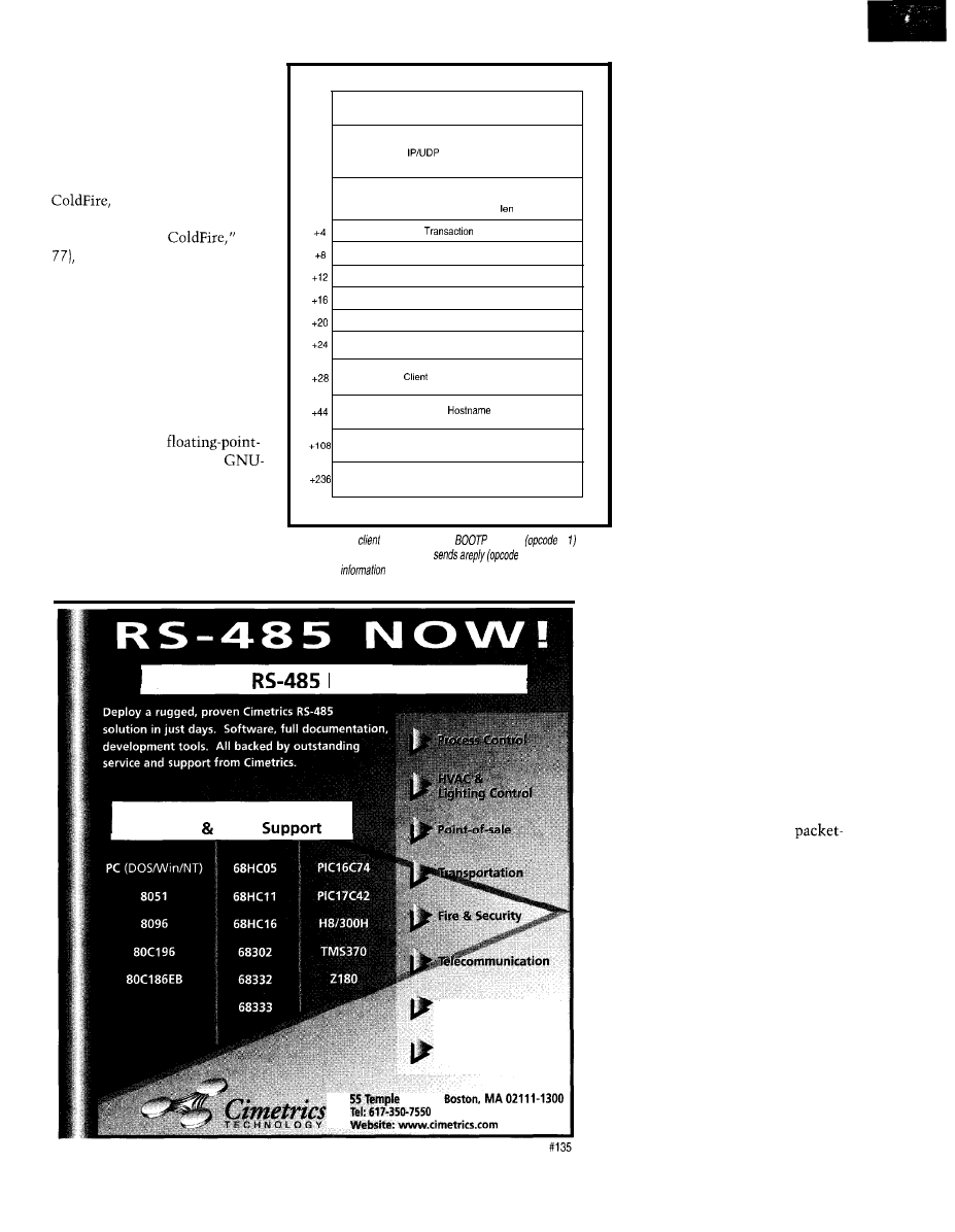
makes it a good tool for embed-
ded-systems programming. It
enables GNU-C to be built as a
cross-compiler and -assembler for
many architectures.
Ethernet Packet Header
Packet Header
I use GNU-C mostly as a
cross-compiler for the 68000 and
Motorola’s new archi-
tecture (see Tom Cantrell’s
“Motorola Lights
INK
on Sun workstations. How-
ever, the 68000 cross-compiler
can be built for almost any OS.
As a C compiler, it behaves as
you’d expect, compiling old-style
C as well as ANSI C into an
object module. It can also com-
pile C++ and Objective C and
even provides a pretty complete
run-time support for the 68000
architecture (e.g.,
math emulation libraries).
C also has many optimization
switches and can optimize code
for almost all the 68000 variants.
+o
Opcode
Hardware
Hardware
Gateway
Address type
Address
Hops
ID
Seconds
Unused
Client Internet Address
“Your” Internet Address
Server Internet Address
Gateway Internet Address
Hardware Address
Server
Filename
Vendor Area
GNU-C is quite amazing, but
the assembler is interesting, too.
Figure
1
--The
broadcasts a
request
= on
the
Ethernet The serverthen
= 2) to the
client
GNU-as can be configured to
with
a//the
the
client
needs to boot
a file from a server.
Standard
Network Software
Comprehensive Microcontroller
Master Slave
68
Issue 88 November
1997
Circuit
Cellar
INK@
Medical Equipment
Laboratory Data
Acquisition
Place
l
l
Fax:
617-350-7552
work as a 68000 assembler, ac-
cepting both Motorola and MIT
syntaxes-the two prevailing
assembler syntaxes for the 68000
family. It can be configured to
generate different object file
formats (e.g., COFF), which are
all supported by the GNU linker.
There is also a source-level
debugger which has remote de-
bugging capability. So at this
point, I can compile C files, as-
semble 68000 assembly-language
modules, and link them all to-
gether into a program on my
Unix workstation. Nice, but how
do I get it into the 68030 system?
There are several options. I
can generate a Motorola S-record
hex file and download it over one
of the serial ports on the 68030
system. But, this method takes a
long time for any program bigger
than a few kilobytes.
I can also extract an image of
the program and its data and
copy it to a floppy that can be
used to boot. This option is pret-
ty
nice, but it requires a floppy drive
on the workstation that can write
floppy disks in “raw” format.
One of the fastest and most conve-
nient methods is network booting. In
Part 2, I wrote about the features of the
monitor on my 68030 system and its
ability to boot from the network.
Here’s how it’s done.
NETWORK BOOTING
Without getting too in-depth about
Ethernet, let me describe what goes
on. Last month, I described the
level driver needed to send and receive
packets to and from Ethernet.
Each packet sent on the net needs
to have a destination address, which in
the case of Ethernet, is sometimes
called the hardware address. The hard-
ware address is a serial number that’s
unique for each Ethernet card.
Since hardware addresses are as-
signed by the manufacturer, they’re
not so useful when it comes to sending
a packet to another machine, unless it
happens to be on the same network
segment. The hardware address has no
information about how to route pack-
ets between network segments.
You heard right.
A quality C
compiler designed for the 8051
microcontroller family, just $200,
including the Intel compatible
assembler and linker. A great
companion to our fine Single
Board Computers, like those
below. CALL NOW!
a ‘5 1 Compatible Micro
40 Bits of Digital
Channels of
10 Bit A/D
3 Serial Ports
or
2 Pulse Width Modulation Outputs
6 Capture/Compare Inputs
1 Real Time Clock
64K bytes Static RAM
1+ UVPROM Socket
512 bytes of Serial EEPROM
1 Watchdog
1 Power Fail Interrupt
1 On-Board Power Regulation
Priced at just $299 in single
quantities. Call about our 552SBC
C Development Kit, just
Other versions of the
hove processors
with
capture registers, EEPROM, IIC,
and more. Call or
for list!
Since 1983
Internet e-mail:
World Wide Web: www.hte.com
Ethernet Packet Header
Packet Header
+o
Opcode
Data
More Data
Figure
client sends a read request packet
(opcode = 1), in which the filename is specified in the
data. After the
responds with an acknowledge
(opcode = the client asks for data
(opcode =
On the Internet, routing is done
with the Internet address. An Internet
address is composed of two parts-a
network number and a host number.
I’m not going to discuss routing issues
any further here, so let’s just say that
Internet addresses are assigned by
network administrators to make the
routing between hosts possible.
But, how does a machine figure out
the hardware address of a host it wants
to send a packet to? And furthermore,
how does the machine discover its
own Internet address?
transmit it. A special broadcast
dress ensures that all machines on the
I’ll answer the second question
first. The machine already knows its
own hardware address.
The monitor uses two protocols to
do this. The boot protocol (BOOTP) is
used to discover the Internet numbers
of the machine and server as well as
the filename of the boot image to load.
Figure
1
depicts a BOOTP packet.
The BOOTP protocol is simple. The
monitor fills out a BOOTP request
packet and uses the packet driver to
and a filename. These are then sent
back to the BOOTP client that origi-
nally broadcasted the request. Listing
1
shows the BOOTP table for our lab.
The client receives the packet and
extracts its Internet address, the Inter-
net address of the server, and the file-
name to download for the boot image.
The monitor then uses the trivial file
transfer protocol (tftp) to read the file
from the boot server.
To discover the server’s hardware
address, the monitor broadcasts an
address resolution protocol (
ARP
) re-
quest packet. This packet basically
asks, “Hey! Who out there has Internet
address
All hosts on the local segment can
hear this packet. If their Internet ad-
dress matches the one requested, they
respond with a packet giving the hard-
ware address. Figure 2 illustrates a tftp
packet, and Figure 3 gives you a look
at the ARP-packet format.
The boot monitor can now contact
the server using its hardware and Inter-
net addresses and download the re-
quested file via tftp. Our BOOTP and
tftp servers are usually the same ma-
chine (i.e., a Sun workstation).
The tftp protocol is fairly simple.
The client requests a certain file and
downloads it a packet at time. Each
packet has a sequence number, and it
is resent if an acknowledge isn’t re-
ceived within a timeout interval.
programs-as part of their normal
ware distribution.
This network-booting scheme has
been around for a while, and Unix
workstations from many vendors have
the appropriate BOOTP and tftn server
segment can see this packet,
since it has no idea which
machines are present on the
local Ethernet segment.
A BOOTP server host has a
table that maps the hardware
address from which the packet
came into an Internet address
Figure
a host wants to find the
hardware address for another host, it
broadcasts a
packet (opcode 1).
The target host responds by
in its
hardware address and sending if back as a
response (opcode = The protocol address
is the
address.
Hardware Address Format
Protocol Address Format
Hardware Address
Protocol Address Len
Opcode
Sender Hardware Address
Sender Hardware Address Cont. Sender Protocol Address
Send Protocol Address Cont.
Target Hardware Address
Target Hardware Address Cont.
Target Protocol Address
Ethernet Packet Header
Packet Header
70
Issue November 1997
Circuit Cellar
Even though this boot method is
fairly popular and reliable, there’s one
problem that makes it unsuitable for
downloading students’ programs in the
lab. There’s no privacy. Since the boot
client has no way to authenticate itself
except by its hardware address, the
system must have provisions for stu-
dents to only be able to download their
own programs.
Furthermore, tftp has no authenti-
cation method, so it essentially acts as
a public-access server. Also, the boot
monitor has no way for students to log
in remotely to edit and compile pro-
grams. Something is clearly missing.
Here’s where the network monitor
comes in. It enables the student to log
in to their Unix account to edit, com-
pile, and download their code in a
secure manner over the network.
The network monitor is based on
the
network OS. This software,
originally written by Phil Karn, is used
by many amateur radio operators to
communicate using packet radio. It
implements a TCP/IP protocol stack
with several clients like telnet and ftp.
I adapted this program to run on my
MC68030 system by stripping out
unneeded features and interfacing it to
some of the drivers I’ve written. The
students boot the network monitor
through the network using the BOOTP
and tftp boot process. Once it’s run-
ning, they can telnet to their Unix
account anywhere on campus.
Once they’re ready to debug, they
can download the image of their pro-
gram into the 32-Kb SRAM, which is
guaranteed to be available on the
68030 system, by using the normal
Internet ftp protocol. ftp lets the stu-
dent log in to their own account and
download only their files.
Once their program is downloaded
into SRAM, they can interrupt out of
the network monitor via a front-panel
push button, which sends an NMI, and
enter the boot-PROM-based debugging
monitor. The student can also resume
the network monitor, assuming their
code didn’t disrupt the saved context
of the network monitor.
CLASSWORK
When students take the
architecture lab, they’ve generally only
been exposed to an introductory C
programming course. So, they have
quite a lot to learn.
They start with the basics of 68000
assembly language and architecture by
doing exercises in which they fill in
missing code segments or explain the
state certain registers are in after ex-
ecuting instructions. The first lab
exercise consists of logging in to their
account and assembling a small ex-
ample which they then download into
the machine using the network.
Once they master a subset of the
68000 assembly language, they quickly
take off and start coding more complex
programs. One of the first really hard
labs is the interrupt lab, in which they
have to write an interrupt-driven key-
board driver based on a polled key-
board driver from an earlier lab.
They then also learn to interface C
modules to their assembly-language
modules which implement the inter-
rupt service routine. The labs’ com-
plexity increases until they culminate
into the final lab. The final lab con-
sists of taking various interrupt-based
I/O drivers and timer routines and
implementing a game (e.g., Tetris or
Missile Command).
FUTURE DIRECTIONS
One of the things I’d like to do with
this system is create a more integrated
debugging environment. I might do
that by implementing some kind of
network-based debugging interface to
the 68030 and integrating it with
GNU’s source-level debugger. Another
possibility is to redesign the 68030
system using a newer processor tech-
nology that implements a hardware
debugging port. Some interesting pro-
cessors include Motorola’s
and PowerPC.
This article concludes my series on
the 68030 system I built for our com-
puter-architecture lab. I hope that I’ve
fueled some interest in the develop-
ment of open architectures and struc-
tures that are suitable for academics
and others as well.
Cyliax is a research engineer in
the Analog VLSI and Robotics Lab
and teaches hardware design in the
computer-science department at Indi-
ana University. He also does software
and hardware development with Deri-
vation Systems, a San Diego-based
formal-synthesis company. You may
reach
at
The schematics, PCB artwork, and
sources for both monitors are avail-
able at
The computer-architec-
ture class using the 68030 system
for the lab has a Web site at
To find out more about
networking, including
on the
protocol discussed, check out
Phil
Karn’s
network OS can be
found at
D. Comer, Internetworking with
Principles, Protocols and
Architecture,
Prentice Hall,
Englewood Cliffs, NJ, 1988.
W. Ford and W. Top, Assembly
Language and Systems Program-
ming for the M68000 Family,
D.C.
Heath and Co., Lexington, MA,
1989.
Tannebaum, Computer Net-
works,
Prentice Hall, Englewood
Cliffs, NJ, 1981.
J.F. Wakerly, Microcomputer Archi-
tecture and Programming, The
68000 Family,
John Wiley & Sons,
New York, NY, 1992.
PowerPC
Motorola
MCU Information Line
P.O. Box 13026
Austin, TX 7871 l-3026
(512) 328-2268
Fax: (512) 891-4465
freeware.aus.sps.mot.com
422 Very Useful
423 Moderately Useful
424 Not Useful
72
Issue 88
November 1997
Circuit Cellar INK@
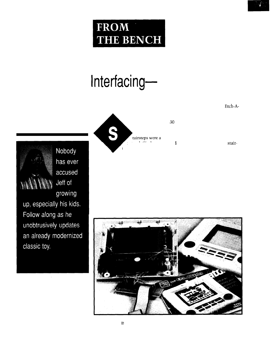
Jeff Bachiochi
Nonintrusive
Using Kid Gloves
natural. Circles, on
the other hand, were
frustratingly elusive.
Good coordination was a must. Hours
of intensive creativity produced only a
brief period of admiration. And then, it
was gone with shake.
Have you guessed? You saw one on
a previous cover of INK. It’s red with
white knobs. One knob draws horizon-
tally, while the other draws vertically.
Yeah, that’s it-the Etch-A-Sketch
from The Ohio Art Company. You
had one as a tyke, right?
The simplicity was elegant. Instead
of drawing on a surface, the Etch starts
by coating the surface with a reflective
material and then proceeds to remove
the coating as you draw.
As the knobs move their appropri-
ate axes, the wiper moves at the inter-
section of the axes. The wiper dis-
lodges the coating from the inside of
the top transparent surface so it drops
off the surface, producing a non-
reflective line.
The only drawback was no perma-
nent record of the masterpiece. And,
then along came electronics. ‘Ohio Art
jumped on the “batteries are better”
bandwagon and produced the
Sketch Animator shown in Photo 1.
The Animator has an LCD screen of
high x 40 wide square pixels. Each
pixel is about one-tenth of an inch.
Two familiar knobs move the cursor
(one square pixel] around the screen.
felt right at home drawing
stepped circles just like I did when I
was young. With square pixels, it’s
impossible to draw perfect circles.
Eight new pushbuttons adorn the
electronic sketch pad. Three buttons
set the creating mode-move, draw,
and erase. With these, you move with-
out affecting the pixels you pass over,
leave a trail of “on” pixels, or leave a
trail of “off” pixels using the x and y
direction knobs.
The next three buttons-save, re-
call, and next-control frames. A
Photo l-The Animator is a rugged electronic version of its predecessor, the Etch-a-Sketch. This photo shows
control circuitry wired the Animator, enabling external control without affecting its manual operation capabilities.
74
Issue 88
November 1997
Circuit Cellar INK@
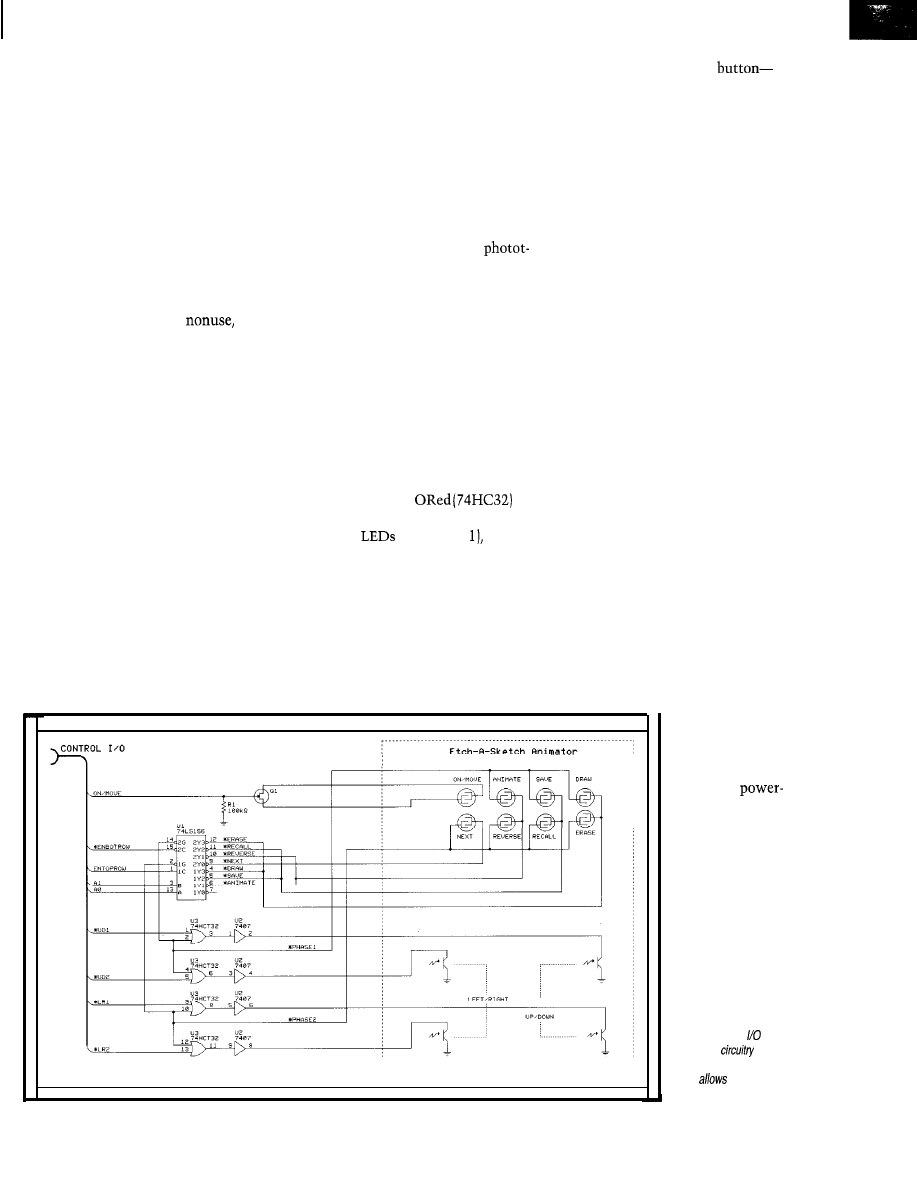
frame is where you place your fin-
ished picture (you’re allowed up to
12). The frame controls let you store
the active picture to the present frame
number, copy the last frame to the
next frame, and move to the next
frame.
The last two buttons are special
effects. The reverse button changes the
state of all pixels (on to off and off to
on). The animate button enables you
to play any of the 12 frames back in
sequence. The sequence can be up to
96 frames in any order.
After three minutes of
the
Animator turns itself off. As long as
the batteries remain in the unit, all the
frames are stored. Changing the batter-
ies erases all the frames.
LOOK, BUT DON’T TOUCH
“Yeah, Dad, you can borrow it, but
please don’t ruin it. I still play with
it.” Kristafer, my youngest, reluctantly
passes over his treasure.
I’m thinking, there must be a way
to make use of this thing without
damaging it. It has a great LC display.
Where’s my screwdriver?
OK. On the inside, it has what
you’d expect. An LCD driver chip, a
processor, and a few glue chips.
All the functions are multiplexed.
Take the x-y control knobs, for in-
stance. They’re similar to rotary en-
coders. For each axis, an LED is aimed
at two phototransistors.
The knob, which looks like one of
those cookie-cutter-style hole saws, is
placed over the receivers so the LED’s
light is blocked by large teeth on the
knob. The receivers are strategically
placed such that when the knob is
turned, the LED’s light hits one and
then the other receiver.
Comparing the phases of the
ransistors’ outputs tells which direc-
tion the knob is turning. The trick
here is that the transmitting LED is
only active for a particular time slot.
So, the phototransistor’s open-collec-
tor output is only actively low during
that particular time slot.
To simulate the x-y knobs, I used
four TTL outputs-a pair for each
knob. By toggling the pairs of outputs
in software, I create the changing
phases, which are interpreted as rotat-
ing a knob one way or the other.
These signals are
with the control signal enabling the
Animator’s
(see Figure which
creates time-slotted outputs. These
outputs are buffered with open-collec-
tor drivers so they can be connected
in parallel to each of the Animator’s
four phototransistor outputs.
The function buttons are much
simpler to control since there is no
direction involved. There are two
The last button I want to discuss is
the on/move button. It has a double
function and cannot be controlled
with a simple open-collector driver.
When the Animator is in sleep
mode, a condition it enters when
activity has ceased for 3 min., all
execution halts to save battery power.
The processor
1
outputs a high to
one side of the
on/move button.
The other side
goes into
on circuitry.
To mimic the
rows of four buttons. One
on/move-operates differently, so
really, there are only three buttons in
the top row of this matrix.
Different time-slot signals, active
low, are applied to the rows. When a
button is pushed, these time slots are
transferred to the column pulling them
low.
Again, I used four TTL signals to
control these functions. A dual 2-4
open-collector decoder (74LS 156)
worked nicely. Two of the TTL signals
are used as address inputs, performing
dual l-of-4 output selection. One set is
used for each row.
The ‘156 has two sets of enables for
each decoder. One set is fed by the
time-slot signals to keep the outputs
active only at the appropriate times.
The other set is controlled by my
other two TTL signals-the key press
enables. By selecting an address and
enabling a row output, a time-slotted
signal is placed in parallel with a
button’s column, faking a physical
button push.
on/move button,
I placed a FET
Figure l--The
interface
uses a
nonintrusive approach
that
human and
machine to coexist.
Circuit Cellar INK@
Issue 88 November 1997
75
across its contacts, with its
bias-
ing
FET off. A ninth
signal
pulses the
gate to imitate the
button being pushed. could have
on all eight pushbuttons,
but
costs would have been
higher.
FIRST BREATH
As you can imagine, this interface
could bc controlled by, most any de-
vice. It simply
nine digital out-
puts.
to use a Domino
to check for signs of
this is an open-loop system, I
wanted to
no commands
would bc missed. Therefore, each
function must execute no
than
minimum time-slot repetition
Domino has a floating-point
BASIC
with lots of code
space. first constructed
routines to
the outputs correctly
to
each of
ten functions the
Animator would recognize-move,
left, right, up, down, draw,
rcversc, next,
recall, animate,
frame, and
animation.
or
a chance it may
not bc seen. On
hand,
too slow wasn’t a problem since it’s
legal to hold a button as long as you
want.
After each routine was functioning
properly, I wrote a test
to
scan the
LCD frame. First,
simply moving
cursor through the
complete frame would give me
minimum
necessary to scan a
frame. It would also give mc the basic
code necessary for navigating a
The minimum time to scan
complete frame is 300 s.
draw
and erase commands
added to
scan to produce a
pattern, the time increased to
s.
using this code and alter-
nately drawing and erasing
pixel
in a checkerboard pattern, I could see
what kind of maximumtime was
necessary to draw an entire frame.
Unlike a television scan, I don’t waste
time returning. to
beginning of
each row. At the
of each row, I just
drop down a row and draw in the
direction.
I
this could bc dccrcascd
thirds
by
control com-
mands from the present in-line
port values to the constant
equivalents. The minimum calculated
scan time based
minimum
time slot repetition rate would bc:
which is:
pixels:: pixels
column
x
scan
TEXT AND GRAPHICS FRAMES
A x block of pixels is of
cicnt size to hold any alphanumeric
character (including a blank column
for interletter spacing or a blank row
for interline spacing). Many letters
require only four columns.
40 x 30 pixel screen can
hold about 40 characters. Since
frames are drawn as a uriit, charac-
ter
can be mixed and can
on the frame.
As a point-of-salt display, the ani-
mation can be used to automatically
The
Generation
PROTEUS
IV for Windows combines Advanced Schematic
Capture, Analogue Digital Simulation with PCB Layout
on Windows
3. I, 8
NT
Told control of drawing appearance.
Mouse driven place. edit, move
Electrical Rules Check.
Circuit
Demand Driven
with Recording.
Mixed Mode Anologue Digital Simulation
PCB
Auto Component
Rip-Up Retry for 100% Routing of boards.
Layers: 16 copper, 2 silk. 4 mechanical.
Most Powerful
System on the market!!!
R4 SYSTEMS INC.
ST.
NEWMARKET ONTARIO
C A N A D A
FREE DEMO
0
WRITE OR
CALL
FAX 905
TODAY
BBS 905
.
Think
is a great technical
r e s o u r c e ?
Do you know anyone who might
appreciate it just-as much?
Most subscribers
get to know us by
reading someone else’s copy. Satisfied
readers are our best supporters.
We’ll
send you a bunch of
copies so you can
show us off. Give us your name, where
you live, and how many you
need.
Contact Rose
(860) 8752199
Thanks for your help.
Issue
88 November 1997
Circuit Cellar
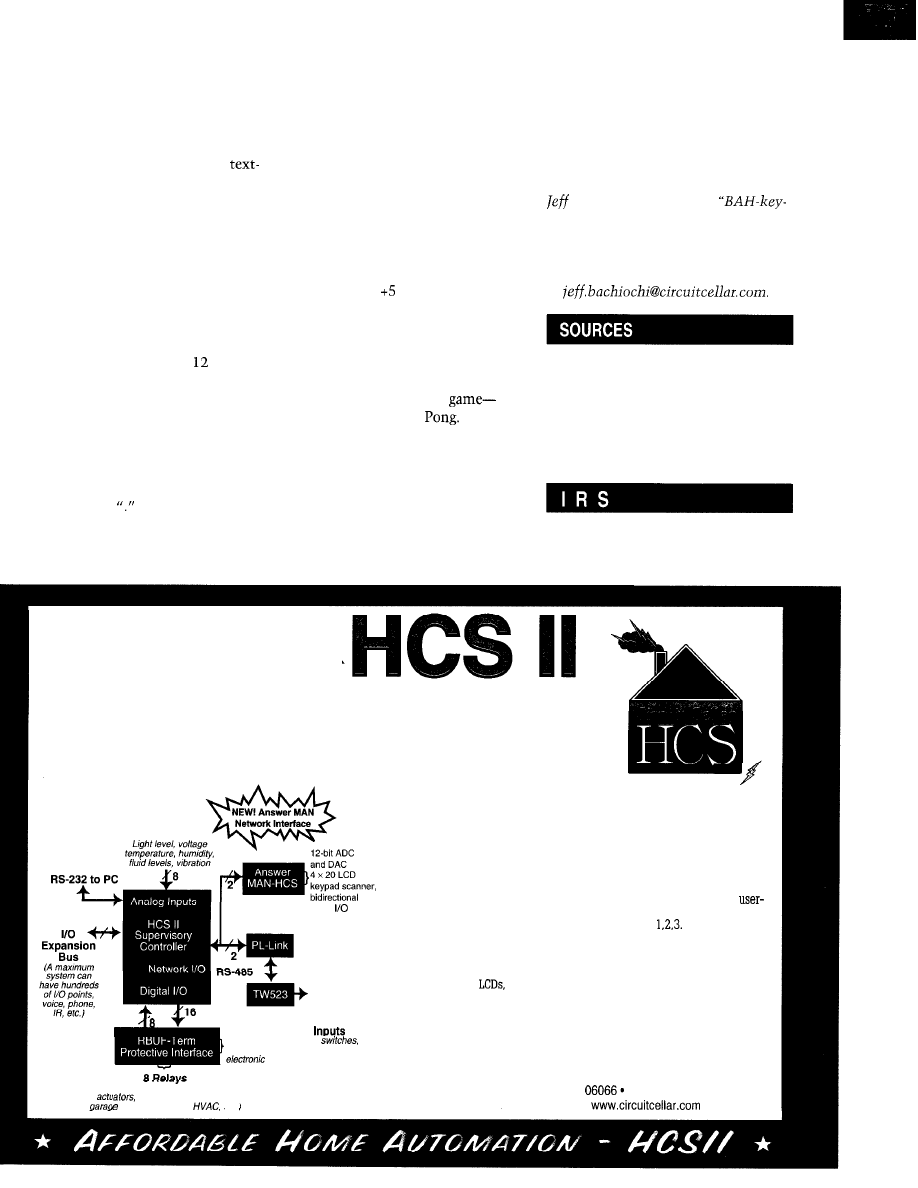
scan through any of the 12 frames of
You can quickly see and edit the
graphics in any 96-frame sequence. Or,
image, and then-voila-it’s saved
the Animator may be commanded to
permanently as a file. The file can be
increment the frame using a variety of
loaded into the Domino and placed
interframe pauses based on the mate-
into any of the Animator’s 12 frames.
rial displayed. This option gives
A serial EEPROM may be used as local
based screens more display time.
nonvolatile storage.
To prevent the Animator from pow-
ering down into a power-saving mode,
a command must be sent at least once
every couple minutes. Various keys
can be used (none of which will alter
the presently displayed frame).
JOY STICKING
FRAME INPUT MODE
Because the Domino has an op-
tional two-channel ADC, an x-y joy-
stick can be connected for better local
control. Apply V across the joy-
stick’s potentiometers, and route the
wipers into the two A/D inputs.
Although the Etch-A-Sketch Ani-
mator is capable of storing differ-
ent frames, like its ancestor, your
work is gone forever once you erase a
frame to draw a new creation. Frame
input mode using the Domino’s serial
input port can accept 30 strings of 40
characters each.
The A/D conversion values are used
to decide which direction pulses to
send to the Animator. Now, this is
more like playing a video
unless you remember
Using a text editor, you can create
a file that uses
(period] and “X” to
signify an erased and drawn pixel. A
carriage return at the end of every row
delimits the line.
So, what did I accomplish? For the
most part, it was an exercise in inter-
facing-the nonintrusive control of an
established system.
At some point, you may be asked
to provide additional functions to a
system where you’re not allowed to
alter the operation of an existing sys-
tem. Redesigns are not always pos-
sible.
And as an engineer, you must be
ready to accept the challenge-no
matter what the constraints. Even if
they come from a nine-year-old.
q
Bachiochi (pronounced
AH-key”) is an electrical engineer on
Circuit Cellar INK’s engineering
staff.
His background includes product design
and manufacturing. He may be reached
at
Domino
Micromint, Inc.
4 Park St.
Vernon, CT 06066
(860) 871-6170
Fax: (860) 872-2204
www.micromint.com
425
Very Useful
426 Moderately Useful
427 Not Useful
CIRCUIT CELLAR
Affordable Home Automation and Security
Our concept of building a home control system is based on the principles
embodied in building an original Heathkit. Besides giving you a project which
details everything from the theory of operation to instructions for fabricating a
functioning system, we give you the sense of confidence that comes from success.
P O W E R
The HCS II is designed with an economical central core and an expand-
able network. A basic system consists of the HCS II central processor,
which incorporates direct analog and digital I/O with real-time event
triggering; a PL-Link wireless X- 10 AC power-line interface which
has sixteen contact-closure/voltage inputs and eight 3-A AC/DC relay
outputs for solenoids, motors, lamps, alarm horns, and so forth.
digital
The house event control sequence is written on a PC in a unique,
friendly control language called XPRESS and stored on the HCS in
nonvolatile memory. Building them is as easy as
Of course, we have lots of extra stuff like our new Answer MAN network
module when you want to expand the basic system. The full HCS has
phone and modem interfaces, infrared remote control, voice
X-l 0 AC Power
Line Control
16 Protected DC
(motion detectors, door
contact closures,
thermostats,
locks, push buttons, etc.)
(AC motors, fans, horns, solenoids,
lamps, water softeners,
doors, door locks,
etc.)
synthesizers,
and much more.
A Circuit Cellar HCS II is not for passive people and definitely not for the
masses. It is for a special technical breed that wants a challenge with
a
tangible reward. Discover the world of manageable and affordable
home automation and security.
Circuit Cellar, Inc.
4 Park St., Vernon, CT
(860) 875-2751
Fax: (860) 871-0411
l
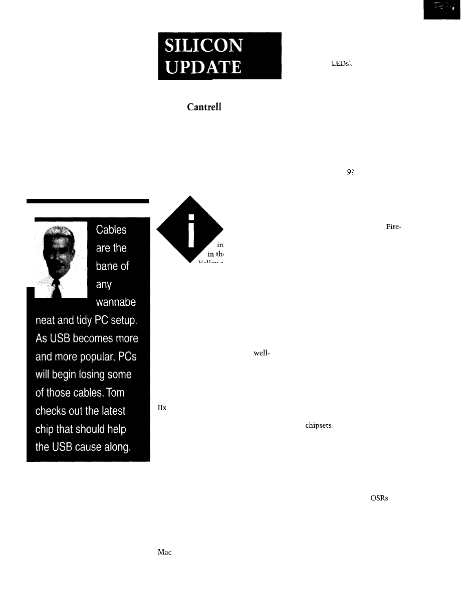
Tom
USB Micro
suppose it’s a bit
ironic that, sitting
in the heart of Silicon
Valley and writing for one
of the highest of high-tech mags, my
own personal stable of computers
practically qualifies as a museum.
ASLEEP AT THE WHEEL
Migrating from old standards to
In fact, I wrote this month’s “Sili-
con Update” on the same machine I
used for my first column lo those
many years ago. It’s a Mac 11x with a
whopping 8 MB of RAM running at a
blazing 15.6672 MHz!
new is often characterized as a chick-
en-and-egg affair. What people forget is
that you can’t just stick an egg on the
shelf and reasonably hope to get a
chicken anytime soon.
My wordsmithing has been
served by this puppy, thanks to a 21”
mono (fewer bits to push around) CRT.
Since for me, the writing process is
actually 99.9% staring at the screen,
I’ve never really missed the MIPS. The
is supplemented by a truly muttly
LC that, hopped up (liberally speaking)
with an accelerator, barely manages to
cope with the ‘Net and a scanner.
On the USB front, progress requires
both a cheap and plentiful collection of
hardware add-ons (e.g., mice, joysticks,
keyboards, etc.) and an OS that knows
what to do with them.
On the PC front, the situation is
even more laughable since I only use a
PC for simple engineering stuff and
don’t expect it to handle more than a
bit of cross-ASM and BASIC twiddling
or EPROM programming from time to
time. The last big development on my
PC front was when I upgraded from
‘286 DOS to ‘386 DOS + Windows 3.1
a few years back.
In this case, there are plenty of eggs,
thanks to Intel’s ever-increasing ability
to decide what PC hardware looks like.
Once they started building USB into
their
and motherboards, it
didn’t take a guru to see the future.
Thus, as I write this (and certainly by
the time you read it), it’s actually get-
ting harder to find a PC without USB
ports on the back than one with.
However, even if you’ve got ‘em,
you may not know it. Short of piddling
snippets of code in arcane
(oper-
ating-system service releases), Micro-
soft isn’t really blessing USB until the
next OS release (Windows 98).
Heaven forbid you should look in
And without significant OS sup-
closet and find the original “toaster”
port, add-on device suppliers and re-
(512 KB of RAM and serial add-on
tailers know that trying to force-march
hard disk). Or, maybe you’ll unearth a
true relic-the IMSAI 8080 with 8”
floppies [and all those lamentably lost
switches and
I suppose I’m the PC exec’s worst
nightmare. More consumers like me,
and the PC market is going to be about
as exciting as the typewriter biz.
Although I appreciate the challenge
of getting the most out of old gadgets, I
know it’s only a matter of time before
my hand (and wallet) is forced. In my
case, I’m hoping to stall until a) I see
whether Steve J. can somehow pull a
rabbit out of his Mac and/orb) Bill G.
gets his Windows act together so
I
can bypass at least one whole genera-
tion of upgrade hassles.
A key inflection point on the PC
front revolves around the next-genera-
tion I/O scheme that relies on the
Universal Serial Bus (USB) and
wire [IEEE 1394) interfaces. I’d really
rather not muck with the ungracefully
aging mishmash of cables and connec-
tors cluttering today’s PCs.
78
Issue
88 November 1997
Circuit Cellar INK@
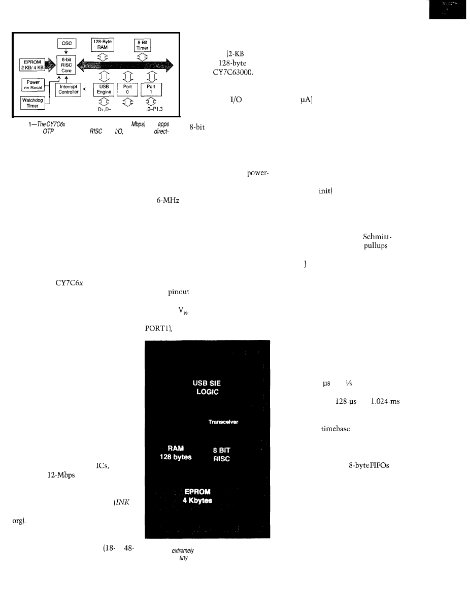
PO.O-PO.7 PI
Figure
family targets low-speed (1.5
USB
by
combining an
EPROM-based
core,
timers, and a
connect USB interface.
users onto USB won’t happen. Without
a chicken, the USB eggs aren’t hatch-
able.
Anyway, short of plaintive calls to
Redmond, there’s nothing much you
or I can do to influence developments
on the OS front. But, observing that
these software developments eventu-
ally muddle through, it’s only a matter
of time before USB finally becomes the
big deal everyone hopes for.
With that in mind, the hardware
guys are still laying eggs at a furious
pace. Let’s take a look at an interesting
example-the
USB Micro
from Cypress Semi.
WELL FARED
Perusing the flyer from a local com-
puter shop, I find mice and joysticks
averaging about $20, with many under
$10 and even one for $0 (fine print
points out you do have to cough up for
the stamp to get the rebate). Obvi-
ously, no $3-5 chip is going to cut it in
such a cost-sensitive market.
So, before getting into the bits and
bytes, let me point out that the Cy-
press chips start at under $2 in volume
and the company claims prices will
bust the buck barrier once things get
rolling.
These entry-level parts only target
low-speed
(1.5
Mbps) apps. (Cypress
also offers higher end hub
which
handle the
segment.) Those
of you who aren’t up to snuff on these
and other USB basics can check out
my “Oh, Say Can USB!” article
74) and log on to the Web (www.usb.
The variety of low-speed offerings
are differentiated by OTP EPROM
capacity (2-8 KB), pin count
to
pin), and package (DIP, SSOP, SOIC).
All can be described by
taking a look at the
minimalist
EPROM,
RAM,
18 pin)
since the higher end
chips simply add gen-
eral-purpose
lines.
As shown in Figure 1,
the chip combines an
MPU with a USB
Serial Interface Engine
(SIE) and transceivers
(for direct cable connection) with mis-
cellaneous accessories such as watch-
dog and general-purpose timers,
on reset, and clock generator. The
latter relies on a PLL to boost an exter-
nal
clock to 12 MHz on chip.
For lowest cost, a ceramic resonator
can be used, but I’d watch out for accu-
racy and drift relative to the USB spec-
ifications. Easing the use of a crystal,
Cypress eliminates the need for the
external bias resistors and feedback
capacitors typically required. A small
touch, but one welcome when your
gadget sells for $0.
The
in Figure 2 is simple
enough, composed of power (V,, for
operation,
for programming),
ground, 12 I/O lines (8 PORT0 and 4
the differential USB signals
Photo 1 -Meeting the under-a-buck price challenge
calls for an
small die-an achievement made
possible by the
size of the CPU core.
D+ and D-, and two clock lines
(XTALIN and XTALOUT).
The only nonobvious pin is CEXT,
which is a dual-function open-collec-
tor output and Schmitt-trigger input.
It’s intended to act as a wake-up alarm
clock to take the chip out of low-pow-
er (100
suspend mode.
The idea is to connect an external
RC, discharge it using CEXT as an
output, switch it to input mode, and
go to sleep. Once the pin charges up,
the chip will wake up in 256 us. Cy-
press calls the feature Instant On, but
it isn’t so much the speed as the fact
that it overcomes the lack of a reset
pin and bypasses the housecleaning
(i.e., register
associated with pow-
er-on reset.
Reflecting the targeted apps, the I/O
lines deliver capabilities uniquely
targeting pointing devices. For in-
stance, all the pins feature
trigger inputs and optional
(handy for buttons), while four of them
(PORT1 offer LED driving capability
to accommodate the typical LED/
phototransistor-based optical mouse
setup.
To tailor power consumption and
slew rate, the outputs include a unique
16-level programmable drive capabil-
ity, shown in Figure 3. And as inputs,
each line can act as an interrupt with
programmable edge polarity.
The 11 -bit timer isn’t general pur-
pose but rather is dedicated to specific
time constants (i.e., it’s read only].
Running at 1 (i.e., the crystal
frequency), the seventh and ninth bits
generate periodic
and
interrupts, respectively. The latter,
further prescaled by 8 (i.e., 8.192 ms)
serves as the
for the watch-
dog timer.
Also, 16 bytes of the on-chip RAM
(128 or 256 bytes, depending on the
chip] are dedicated as
for
the two endpoints supported by the
chip. Endpoint 0, required of all USB
devices, is used during initialization to
enable the host PC to determine what
is out there-a process known as enu-
meration. Endpoint 1 is where the
bulk of the action occurs.
The rest of the RAM handles sepa-
rate program and data stacks with user
variables sandwiched in between.
Circuit Cellar INK”’
Issue 88 November 1997
79
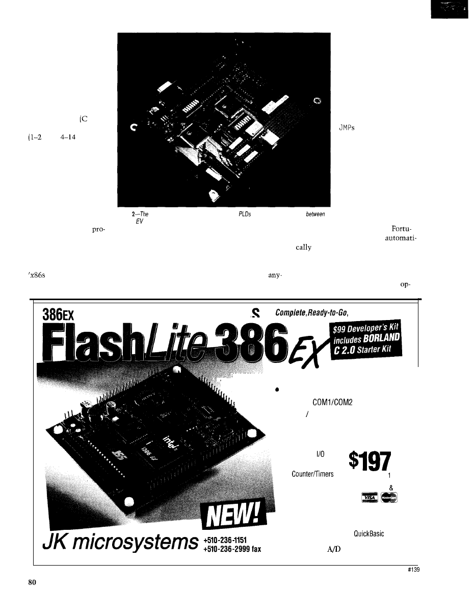
REDUCED-IN-SIZE
COMPUTER?
The Cypress MPU
core reflects the latest
RISC trend-namely,
“Call it a RISC, no mat-
ter what it is.” In fact,
with an accumulator (A),
single index register (X),
condition codes and
Z), and variable-length
byte,
clock)
instructions, it looks
more like a 6805 or 6502
than anything found in a
computer-science book.
about
10
minutes in the
datasheet to qualify as an
expert.
Of course, beyond the
typical moves, branches,
and ALU ops, there are a
few quirks to keep things
interesting. For one, you
as a programmer only
have direct access (via
and
CALL
S
)
to
the
lower
12 bits of the PC.
For chips with more than
4 KB of ROM, this means
jumping through a few
hoops.
Anyway, I’ve long
gotten over any feelings
of righteous indignation
over abuse of the RISC
term, and Cypress cer-
tainly isn’t alone in
Photo
Cypress
Development System relies on
to achieve functionality
a
low-end
board and a full-featured ICE.
Furthermore, the PC
doesn’t automatically
roll over past 8 bits, so a
special instruction
(XPAGE)
is provided to
increment bit 9.
mulgating such dubious marketspeak.
The good news is, with only a few
nately, an assembler option
RISC, SHMISC-who gives a hoot?
dozen instructions and three measly
inserts X
PAGE
[with aligning N 0
P,
These days, all chips are either an ‘x86,
addressing modes [i.e., direct, indexed,
if necessary) at each page boundary so
RISC, or VLIW, the irony being the
and immediate), this puppy is real easy
you don’t have to keep track of it.
are themselves morphing into
to understand. It should not take
Alternatively, those turned on by
RISC (and soon, VLIW?) inside.
one beyond neophyte stage more than
clever optimization can stop the
Embedded Controller with DO,
No Hidden Costs!
l
Includes DOS, utilities, flash file support.
32-bit processor runs 386 protected mode
l
Complete
PC compatibility
l
386EX 25 MHz
l
Up to 512K SRAM, up to 512K Flash
l
Sockets to add 512K Flash/RAM/EPROM
l
2 Serial Ports
QTY 100
l
24 Parallel lines
l
Watchdog Timer
l
3
$239 QTY
l
3 free interrupt lines
includes 128K
RAM
512K flash DOS
l
Battery-backed RTC
l
2 DMA Channels
l
High-efficiency switching power supply
l
IBM PC speaker
l
Program in Borland C or
Fast, low-cost
converter and relay
Cost effective controller? for
industry
www.jkmicro.com
boards are also available.
Issue 88 November 1997
Circuit Cellar
INK”
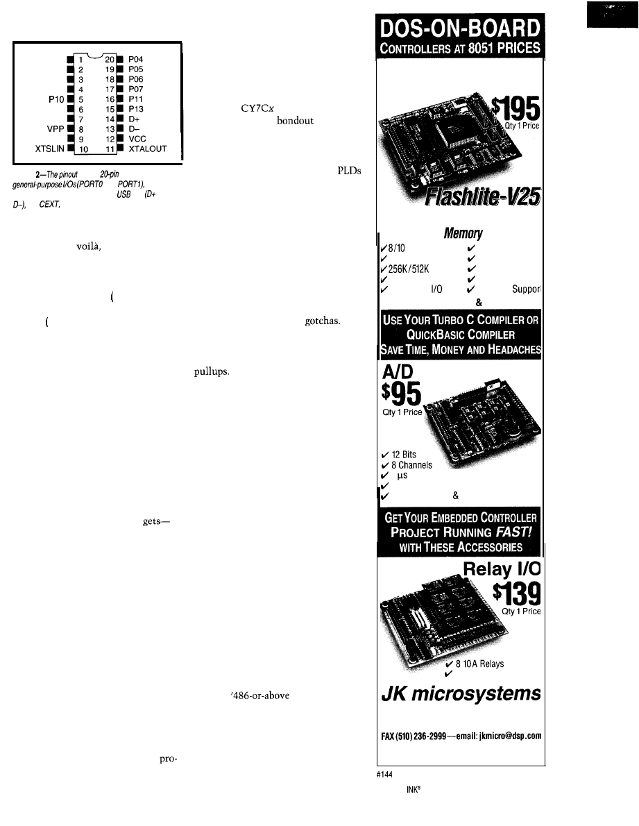
PO0
PO1
PO2
PO3
P12
v s s
CEXT
Figure
of the
version shows 12
and
power and
clock
connections, the differential
pair and
and
which delivers a periodic wake-up call
when connected to an external resistor.
tion, make sure their loops are exactly
256 bytes, and
“Look Ma, a loop
with no
JMP.”
A more useful streamliner-the
I P R ET instruction-writes the accu-
mulator to an I/O port
I ),
pops the old
accumulator off the stack
(P),
and
returns
RET),
replacing the three in-
structions otherwise needed to skirt
the accumulator bottleneck.
In fact, in a refreshing departure,
Cypress even badmouths the conven-
tional posture (if not wisdom) of HLL,
pointing out that ASM is the way to
go. I don’t know how long their PR
machine can hold out against the
clamor for C, but I give ‘em Brownie
points for trying.
Bringing to mind the original VW
bug, the CPU core may not have a lot
of horsepower or fancy options, but it’s
certainly a miserly silicon sipper. Just
take a look at Photo
1
to see how tiny
a share of real estate the CPU
more astounding when you realize the
entire die is less than 0.1” on a side!
DRIVER TRAINING
Getting up to speed with the Cy-
press chips is easy, thanks to their
$495 USB development board (see
Photo 2). The unit delivers functional-
ity somewhere between that of the
typical low-end ROM monitor EV
board and a full-featured ICE.
Like the former, it relies on down-
loading your program into RAM and
delivers full-speed operation, but only
when not otherwise occupied handling
a breakpoint or dumping a watch vari-
able. However, it does exhibit ICE-like
capabilities in that there’s no memory
or I/O resources stolen from your
gram-a key point since forgoing any
of the chip’s limited memory space
would likely cramp your style.
The cute trick making this all pos-
sible is that the unit isn’t built around
a standard
part. Indeed, it uses
the equivalent of a
chip often
found in full-featured emulators. I say
“equivalent” because, instead of a
monolithic custom IC, the setup uses
a pair of the company’s high-end
programmed to deliver both the func-
tionality of the USB chip and ancillary
logic (e.g., the UART that connects the
board to a PC).
This configuration permits internal
signals (e.g., address, data, int request
and acknowledge, etc.) that are inac-
cessible on a standard chip to be
brought out to headers. So, you can
hook up a logic analyzer or trace buffer
to track low-level operations.
There are a few minor
For
example, the general-purpose I/O lines’
programmable current-drive feature
isn’t available nor are the internal
These minor differences can
easily be handled as last-second soft-
ware bolt-ons, and they certainly
aren’t showstoppers when developing
the guts of your applications.
Closing the hood for now, the bot-
tom line is that the board delivers the
usual and adequate mix of capabilities
[e.g., breakpoints, single step, memory
and I/O access, etc.). Nothing too
fancy, mind you (i.e., no breakpoint
qualifiers), but it’s enough to get your
USB app cranked up and rolling.
On the software side, a workman-
like Windows (3.1 and 95 compatible,
thank you) front end does the job with-
out a lot of muss and fuss.
I did have a bit of trouble during
installation. My floppy choked on one
of the files, but I simply dismissed the
ominous-sounding error messages with
a thoughtfully provided
i g
n o r e
but-
ton. (I’ve encountered other software
that punches you out with no recourse
in similar circumstances.)
I
paused just briefly before jetting
past the
warning in the
documentation. The fact that I got past
those potholes, and haven’t encoun-
tered any since, is a good sign. Overall,
the software seems robust and easy to
use.
Use Your PC Development Tools
No More Crash and Burn EPROM
DOS Single Board Computer
with FLASH
‘disk drive’
MHz CPU
2 DMA channels
512K bytes RAM
2 Timers
FLASH
4 Interrupt Lines
2 Serial Ports
8 Analog Inputs
20 Parallel Lines Xmodem
INCLUDES DOS Utilities
Converter
6 Conversion fime
Clock/Calendar Option
Includes Drivers Apps.
8 Opto-Isolated Inputs
Cost Effective Controllers for Industry
TO ORDER (510) 2364151
Visit our WEB site-www.jkmicro.com
1275 Yuba Ave., San Pablo, CA 94806
Circuit Cellar
Issue 98 November 1997
83
T I 0
Remote Control
“Total
by
Operate TV, lamps and other
appliances from up to 100 feet.
Includes two receivers on sepa-
rate frequencies and a two bu
ton hand-held transmitter that
controls them. Requires 9 volt
battery (not included).
CAT # TCR-1
PAINFULLY BRIGHT RED LED
2500
to 4000 mcd 20 ma. T 1
(5 mm diameter) red LED. Significantly
brighter than conventional
Water
clear in off-state.
CAT # LED-42
10 for $5.00
l
100 for $45.00
1000 for $400.00
2
8 Ohm Speaker
Panasonic #
8 ohm 0.4 watt speaker with
soft-edge paper cone producing
good sound quality. 0.93” overall
depth. 2.25” wire leads with
2 contact (0.1” spacing)
socket connector.
Large
available.
Low Power Audio Amp
MC341
power audio amplifier suitable
or speakerphones or talking picture
Operates on 2 16 volts and
drives speakers of 8 ohms or greater. Output
power exceeds 250
with 32 ohm speaker.
Hook-up sheet. Large quantity available.
6 0
CAT
each
50 Pieces $25.00
NO MINIMUM
ORDER
and
for
U S A $5 per order All others
AK.
PR or Canada
pay full
All
orders
CALIFORNIA
Include local state sales tax
NO COD
WRITE
or E-MAIL
for
our FREE
96 Page
CATALOG
Outside the
U.S.A.
change
Port
Register
Port Data
16
Data Bus
q Pin
Figure
general-purpose lines
and
are especially
including programmable
input conditioning, and programmable current
drive. In addition,
can drive
(up to 24
per line,
total), and lines can serve as interrupt inputs with
programmable polarity.
Some might argue the
communication rate is a little poky,
since every second seems to count
when you’re in the middle of an
ASM-download-debug frenzy. The
small size of programs lets Cypress
skate by on this one.
I do suggest that they (and all others
who use PC serial connections) in-
clude a port-finder feature that simply
sits in a loop waiting for you to get
your cable, gender changer, and port
right. I had to spend a bit more
than the usual few minutes getting
connected.
The package also includes an as-
sembler (DOS based, which is fine
with me) and particularly helpful ex-
ample programs, including one for a
mouse. Anyone who’s ever delved into
a new I/O protocol, particularly one as
complex as USB, knows that having an
actual example to study is much better
than simply wading through the
from scratch.
In fact, the MOUSE. DOC file gives
directions on how to hack a mouse by
removing the microcontroller and
jacking the Cypress chip in (i.e., con-
nect to the
phototransistors, and
buttons). If all goes well, you can con-
nect the whole mess to a USB-enabled
PC, subject to the fine-print caveats
about having the right betas and
tweaking the registry, and so on.
ALL ABOARD
The Cypress chips aren’t the first
targeting USB, and they won’t be the
last. Nevertheless, the fact that they’re
real-and real cheap (not to mention
nicely supported)-gives them a leg up.
Remember, even if you’re not
in the mouse or joystick biz, USB
is going to be a big deal. For in-
stance, perusing INK, you’ll see
plenty of ads and articles describ-
ing myriad data-acquisition and
process-control gizmos that con-
nect to a PC serial port, all of
which are likely candidates for
hopping on USB.
Keithley Instruments, for ex-
ample, has already announced the
Smartlink family of USB-based
distributed I/O modules. And
they’re priced the same as their
older RS-232 counterparts.
Yes, departure of the USB bus is a
little overdue. But once the driver
wakes up (perhaps after gulping down
some Java?), expect to see the USB
pedal hit the metal.
q
Tom Cantrell has been working on
chip, board, and systems design and
marketing in Silicon Valley for more
than ten years. You may reach him by
E-mail at
corn, by telephone at (510) 657-0264,
or by fax at (510) 657-5441.
USB Micro
Cypress Semiconductor
3901 N. First St.
San Jose, CA 95134
(408) 943-2600
Fax: (408) 943-6848
www.cypress.com
Smartlink
Keithley Instruments, Inc.
28775 Aurora Rd.
Cleveland, OH 44139
(216) 248-0400
Fax: (216) 248-6168
www.keithley.com
USB Implementers Forum
2111 NE 25th Ave.,
Hillsboro, OR 971245961
(503) 264-0590
Fax: (503) 693-7975
428
Very Useful
429 Moderately Useful
430 Not Useful
84
Issue 88 November 1997
Circuit Cellar
INTERRUPT
Your Unbiased Advocate
was a tough job, but somebody had to do it. What am talking about? Judging a contest, of course.
Believe me. don’t volunteer gracefully. As an unbiased advocate dedicated to the low-cost dissemination
of embedded control technology, I’m expected to participate. But, as a sometimes bitter and warped
conscious hardware-oriented design engineer, they better watch out.
All kidding aside, being a contest judge sounds like a glamorous job. It isn’t! Take my current experience with INK’s just-concluded
Embedded PC Design Contest. Next month, we’ll have a write-up on the entries, but tell you now that Mark Roberts is the big first-prize
winner. It also turned out that he won third prize as well! If you think that’s strange, then how do you feel about the second-prize winner,
Brad Reed, also winning a fourth-place honorable mention?
Somewhere between my saying to Janice, “You’ve got to be kidding!” and “Who the hell’s going to believe this?,” I blotted my brow and
said, guess it’s editorial time.”
I swear on a stack of Pentiums that the results of the contest are absolutely honest and the fact that two winners walked off with over
half the prizes is purely coincidental. The judges never saw the entry forms, and all the contest materials we reviewed had the contestant’s
name or other identifying features removed. While we, as judges, might have seen some similarity in the writing style and quality of multiple
single-author entries, I made a special attempt to judge each individually. I’m sure the others did the same. While multiple entries from a
single contestant were not typical, there were a significant number. In fact, two industrious contestants submitted three.
The reality of the outcome is that the quality of the entry spoke for itself. Mark Roberts won because he followed the rules of the
contest and executed it precisely. If he had the formula correct enough to win first place, it is only certification of his credible talents that a
second entry following the same formula would be an equal contender. Similarly, Brad Reed zeroed in on the correct recipe for winning. The
result was a real fight for the top spots.
While most contest rules are basic, the
contest rules were specifically intended to promote participation rather than excessive
entry expense. Unlike the physical-demonstration design contests that we’ve sponsored in the past, an
contest entry consisted of a
detailed engineering specification instead. As you might guess, the content and quality of these submissions varied greatly. It’s only logical
that someone familiar with writing specifications or proposals would have a leg up on the process.
Nonetheless, when there is $10,750 in prize money on the table, a review of the process is always in order. Given the remarkable
conclusions, you can bet we reviewed it quickly. In the end, my opinion is that the judges were a damn picky lot. Perhaps because the
judges are professionals with serious credentials and extensive embedded-control knowledge, they evaluated these specifications as real
proposals. While I should have expected nothing less from them (or myself), they reacted severely to contestants who tended toward
overkill in their selection of hardware components or who chose software with inadequate capability, regardless of how unique or daring the
concept. The judges sifted through the piles of paper and simply selected specifications worthy of being presented in a real company
environment.
It’s obvious that a computer professional used to the technical-proposal process and a good writer may have a decided advantage. As
you might have guessed, a crash-and-burn solder-sniffing engineer (like myself) has a different
In the end, however, the sponsors’ goals were achieved. The winning entries demonstrated relevant use of the sponsors’ products and
descriptions of the winning entries will certainly pique reader interest. If you sat on the bench for the Embedded PC Design Contest, you
have another opportunity with
Of course, the “unbiased advocate” gets drafted again as a tie-breaker judge. Sometimes I wonder
if I should be a bit more biased.
96
Issue 88 November 1997
Circuit Cellar
Wyszukiwarka
Podobne podstrony:
circuit cellar1996 11
circuit cellar1993 11
circuit cellar1994 11
circuit cellar2004 11
circuit cellar2000 11
circuit cellar1995 11
circuit cellar2002 11
circuit cellar2001 11
circuit cellar2003 11
circuit cellar1996 11
circuit cellar1993 11
circuit cellar1995 11
circuit cellar1996 11
circuit cellar2003 11
circuit cellar1997 11
circuit cellar1993 11
więcej podobnych podstron