
Software Update F.02.xx Release Notes
for the
HP ProCurve Series 2500 Switches
Topics:
■
TACACS+ Authentication for Centralized Control of Switch Access Security (page 7)
■
CDP (page 29)
■
New Time Synchronization Protocol Options (page 43)
■
Operation and Enhancements for Multimedia Traffic Control (IGMP) (page 63)
■
Switch Memory Operation (page 70)
■
Port Security: Changes to Retaining Learned Static Addresses Across a Reboot (page 71)
■
Username Assignment and Prompt (page 72)
■
Series 2500 FAQs from the HP Procurve Website (page 73)
■
Updates and Corrections for the Management and Configuration Guide (page 76)
C a u t i o n : A r c hi v e P r e - F. 0 2 . x x C o n f i g u r a t i o n F i l e s
A configuration file saved while using release F.02.xx software cannot be used on a switch having
software release F.01.xx. For this reason, HP recommends that you archive the most recent config-
uration on switches using software release F.01.xx before you update any switches to software
release F.02.xx.

© Copyright 2001 Hewlett-Packard Company
All Rights Reserved.
This document contains information which is protected by
copyright. Reproduction, adaptation, or translation without
prior permission is prohibited, except as allowed under the
copyright laws.
Publication Number
5969-2371
January 2001
Applicable Product
HP ProCurve Switch 2512 (J4812A)
HP ProCurve Switch 2524 (J4813A)
Trademark Credits
Microsoft, Windows, Windows 95, and Microsoft Windows
NT are registered trademarks of Microsoft Corporation.
Internet Explorer is a trademark of Microsoft Corporation.
Ethernet is a registered trademark of Xerox Corporation.
Cisco® is a trademark of Cisco Systems, Inc.
Disclaimer
The information contained in this document is subject to
change without notice.
HEWLETT-PACKARD COMPANY MAKES NO WARRANTY
OF ANY KIND WITH REGARD TO THIS MATERIAL,
INCLUDING, BUT NOT LIMITED TO, THE IMPLIED
WARRANTIES OF MERCHANTABILITY AND FITNESS
FOR A PARTICULAR PURPOSE. Hewlett-Packard shall not
be liable for errors contained herein or for incidental or
consequential damages in connection with the furnishing,
performance, or use of this material.
Hewlett-Packard assumes no responsibility for the use or
reliability of its software on equipment that is not furnished
by Hewlett-Packard.
Warranty
See the Customer Support/Warranty booklet included with
the product.
A copy of the specific warranty terms applicable to your
Hewlett-Packard products and replacement parts can be
obtained from your HP Sales and Service Office or
authorized dealer.
Hewlett-Packard Company
8000 Foothills Boulevard, m/s 5552
Roseville, California 95747-5552
http://www.hp.com/go/hpprocurve

3
Contents
Series 2500 Switch Authentication Options . . . . . . . . . . . . . . . . . . . . . . . . . . . . . . . . . . . . . . . . . . . . . . . . . . 8
Terminology Used in TACACS Applications: . . . . . . . . . . . . . . . . . . . . . . . . . . . . . . . . . . . . . . . . . . . . . . . 9
General System Requirements . . . . . . . . . . . . . . . . . . . . . . . . . . . . . . . . . . . . . . . . . . . . . . . . . . . . . . . . . . . 10
TACACS+ Operation . . . . . . . . . . . . . . . . . . . . . . . . . . . . . . . . . . . . . . . . . . . . . . . . . . . . . . . . . . . . . . . . . . 11
General Authentication Setup Procedure . . . . . . . . . . . . . . . . . . . . . . . . . . . . . . . . . . . . . . . . . . . . . . . . . . . 11
Configuring TACACS+ on the Switch . . . . . . . . . . . . . . . . . . . . . . . . . . . . . . . . . . . . . . . . . . . . . . . . . . . . 14
Controlling Web Browser Interface Access When Using TACACS+ Authentication . . . . . . . . . . . . . . . . 26
Messages . . . . . . . . . . . . . . . . . . . . . . . . . . . . . . . . . . . . . . . . . . . . . . . . . . . . . . . . . . . . . . . . . . . . . . . . . . . 26
Operating Notes . . . . . . . . . . . . . . . . . . . . . . . . . . . . . . . . . . . . . . . . . . . . . . . . . . . . . . . . . . . . . . . . . . . . . . 27
Troubleshooting TACACS+ Operation . . . . . . . . . . . . . . . . . . . . . . . . . . . . . . . . . . . . . . . . . . . . . . . . . . . . 27
Introduction . . . . . . . . . . . . . . . . . . . . . . . . . . . . . . . . . . . . . . . . . . . . . . . . . . . . . . . . . . . . . . . . . . . . . . . . 29
CDP Terminology . . . . . . . . . . . . . . . . . . . . . . . . . . . . . . . . . . . . . . . . . . . . . . . . . . . . . . . . . . . . . . . . . . . . 30
General CDP Operation . . . . . . . . . . . . . . . . . . . . . . . . . . . . . . . . . . . . . . . . . . . . . . . . . . . . . . . . . . . . . . . . 30

4
CDP Neighbor Data and MIB Objects . . . . . . . . . . . . . . . . . . . . . . . . . . . . . . . . . . . . . . . . . . . . . . . . . . . . . 40
Operating Notes . . . . . . . . . . . . . . . . . . . . . . . . . . . . . . . . . . . . . . . . . . . . . . . . . . . . . . . . . . . . . . . . . . . . . . 42
Troubleshooting CDP Operation . . . . . . . . . . . . . . . . . . . . . . . . . . . . . . . . . . . . . . . . . . . . . . . . . . . . . . . . . 42
New Time Synchronization Protocol Options . . . . . . . . . . . . . . . . . . . . . . .43
TimeP Time Synchronization . . . . . . . . . . . . . . . . . . . . . . . . . . . . . . . . . . . . . . . . . . . . . . . . . . . . . . . . . . . . 43
SNTP Time Synchronization . . . . . . . . . . . . . . . . . . . . . . . . . . . . . . . . . . . . . . . . . . . . . . . . . . . . . . . . . . . . 44
Overview: Selecting a Time Synchronization Protocol or Turning Off Time Protocol Operation . . . . . . . 44
Viewing the Current TimeP Configuration . . . . . . . . . . . . . . . . . . . . . . . . . . . . . . . . . . . . . . . . 56
Configuring (Enabling or Disabling) the TimeP Mode . . . . . . . . . . . . . . . . . . . . . . . . . . . . . . 57
Menu Interface Operation with Multiple SNTP Server Addresses Configured . . . . . . . . . . . . . 62
Operation and Enhancements for Multimedia Traffic Control (IGMP) . .63
How Data-Driven IGMP Operates . . . . . . . . . . . . . . . . . . . . . . . . . . . . . . . . . . . . . . . . . . . . . . . . . . . . . . 63
New: IGMP Now Operates With or Without IP Addressing . . . . . . . . . . . . . . . . . . . . . . . . . . . . . . . . . 64
Fast-Leave IGMP . . . . . . . . . . . . . . . . . . . . . . . . . . . . . . . . . . . . . . . . . . . . . . . . . . . . . . . . . . . . . . . . . . . . . 65
New: Forced Fast-Leave IGMP . . . . . . . . . . . . . . . . . . . . . . . . . . . . . . . . . . . . . . . . . . . . . . . . . . . . . . . . . . 67
Querier Operation . . . . . . . . . . . . . . . . . . . . . . . . . . . . . . . . . . . . . . . . . . . . . . . . . . . . . . . . . . . . . . . . . . . . . 69
The Switch Excludes Well-Known or Reserved Multicast Addresses from IP Multicast Filtering . . . . . . 70

5
Username Assignment and Prompt . . . . . . . . . . . . . . . . . . . . . . . . . . . . . . .72
Series 2500 FAQs from the HP Procurve Website . . . . . . . . . . . . . . . . . . .73
Updates and Corrections for the Management and Configuration Guide 76

6
7
TACACS+ Authentication for Centralized Control
of Switch Access Security
TACACS+ Features
TACACS+ authentication enables you to use a central server to allow or deny access to Series 2500
switches (and other TACACS-aware devices) in your network. This means that you can use a central
database to create multiple unique username/password sets with associated privilege levels for use
by individuals who have reason to access the switch from either the switch’s console port (local
access) or Telnet (remote access).
N o t e
In release F.02.xx, TACACS+ authentication does not affect web browser interface access. For
steps to block unauthorized access through the web browser interface, see “Controlling Web
Browser Interface Access When Using TACACS+ Authentication” on page 26.
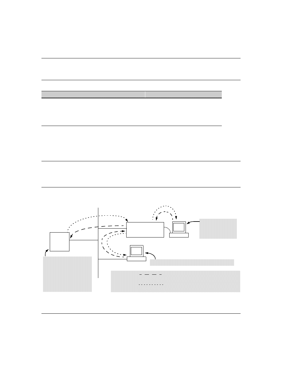
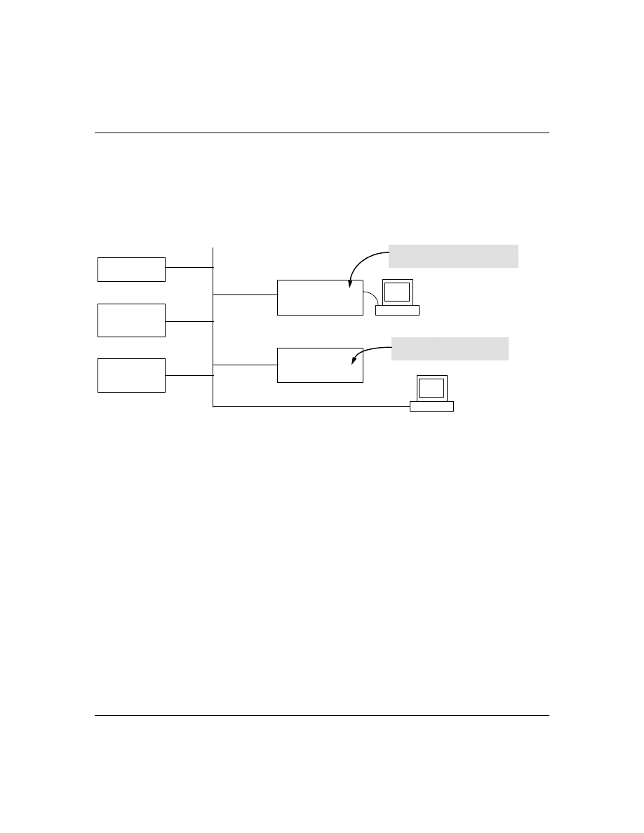
Figure 1. Example of TACACS+ Operation
Feature
Default
Menu
CLI
Web
view the switch’s authentication configuration
n/a
—
page 14
—
view the switch’s TACACS+ server contact configuration
n/a
—
page 15
—
configure the switch’s authentication methods
disabled
—
page 15
—
configure the switch to contact TACACS+ server(s)
disabled
—
page 19
—
B
Series 2500 Switch
Configured for
TACACS+ Operation
Terminal "A" Directly
Accessing the Switch
Via Switch’s Console
Port
Terminal "B" Remotely Accessing The Switch Via Telnet
A
Primary
TACACS+
Server
The switch passes the login
requests from terminals A and B
to the TACACS+ server for
authentication. The TACACS+
server determines whether to
allow access to the switch and
what privilege level to allow for
a given access request.
Access Request A1 - A4 : Path for Request from
Terminal A (Through Console Port)
TACACS Server B1 - B4: Path for Request from
Response Terminal B (Through Telnet)
B1
A2 or
B2
A3 or
B3
B4
A1
A4

8
With authentication configured on the switch and TACACS+ configured and operating on a server in
your network, an attempt to log on through Telnet or the switch’s serial port will be passed to the
TACACS+ server for verification before permission is granted. Similarly, if an operator is using read-
only access to the switch and requests read-write access through the CLI
enable
command by entering
a user name and password, the switch grants read-write access only after the TACACS+ server verifies
the request and returns permission to the switch.
N o t e
Software release F.02.xx for the Series 2500 switches enables TACACS+ authentication, which is the
ability to allow or deny access to a Series 2500 switch on the basis of correct username/password
pairs, and to specify the privilege level to allow if access is granted. This release does not support
TACACS+ authorization or accounting services.
Series 2500 Switch Authentication Options
With software release F.02.xx installed, the Series 2500 switches include these types of authentica-
tion:
■
Local:
Employs a username/password pair assigned locally to the switch. This option allows
one username/password pair for manager-level privileges and another username/password
pair for operator-level privileges. Local authentication is automatically available in the
switch. The Management and Configuration Guide you received with your switch describes
this method.
■
TACACS+:
Employs a username/password pair assigned remotely to a TACACS+ server
application. This option allows multiple username/password pairs for any privilege level
available on the switch. The remainder of this section describes TACACS+ authentication
on the Series 2500 switches.
■
None:
The switch can be accessed by anyone without requiring a username/password pair.
This is the case when TACACS+ is not enabled on the switch and a local, manager-level
password is not configured in the switch. Allowing the switch to operate in this mode is not
recommended because it compromises switch and network access security.
TACACS+ on the Series 2500 switches
uses an authentication hierarchy consisting of remote control
through a TACACS+ server and the local control (password and user name) built into the switch.
That is, with TACACS+ configured on the switch, if the switch cannot contact any designated
TACACS+ server, then it defaults to its own locally assigned username/password pairs to control
access. To use TACACS+ authentication in a Series 2500 switch, you must enable TACACS+ in the
switch and also purchase, install, and configure a third-party TACACS+ server application on the
device(s) in your network that you want to use for managing TACACS+ authentication.

9
Terminology Used in TACACS Applications:
■
NAS (Network Access Server):
This is an industry term for a TACACS-aware device that
communicates with a TACACS server for authentication services. Some other terms you may
see in literature describing TACACS operation are communication server, remote access
server
, or terminal server. These terms apply to a Series 2500 switch when TACACS+ is
enabled on the switch (that is, when the switch is TACACS-aware).
■
TACACS+ Server:
The server or management station configured as an access control server
for TACACS-enabled devices. To use TACACS+ with the Series 2500 switches and any other
TACACS-capable devices in your network, you must purchase, install, and configure a
TACACS+ server application on a networked server or management station in the network.
The TACACS+ server application you install will provide various options for access control
and access notifications. For more on the TACACS+ services available to you, see the
documentation provided with the TACACS+ server application you will use.
■
Authentication:
The process for granting user access to a device through entry of a user
name and password and comparison of this username/password pair with previously stored
username/password data. Authentication also grants levels of access, depending on the
privileges assigned to a user name and password pair by a system administrator.
•
Local Authentication:
This method uses username/password pairs configured locally
on the switch; one pair each for manager-level and operator-level access to the switch.
You can assign local usernames and passwords through the CLI or web browser
interface. (Using the menu interface you can assign a local password, but not a user-
name.) Because this method assigns passwords to the switch instead of to individuals
who access the switch, you must distribute the password information on each switch to
everyone who needs to access the switch, and you must configure and manage password
protection on a per-switch basis. (For more on local authentication, see the password
and username information in the Configuration and Management Guide shipped with
your Series 2500 switch.
•
TACACS+ Authentication:
This method enables you to use a TACACS+ server in your
network to assign a unique password, user name, and privilege level to each individual
or group who needs access to one or more switches or other TACACS-aware devices.
This allows you to administer primary authentication from a central server, and to do
so with more options than you have when using only local authentication. (You will still
need to use use local authentication as a backup if your TACACS+ servers become
unavailable.) This means, for example, that you can use a central TACACS+ server to
grant, change, or deny access to a specific individual on a specific switch instead of
having to change local user name and password assignments on the switch itself, and
then have to notify other users of the change.

10
General System Requirements
To use TACACS+ authentication, you need the following:
■
Release F.02.xx or later software running on your Series 2500 switch. Ensure that software
release F.02.xx or later is running on your switch. Use any of the following methods to view
the current software version:
CLI:
HP2512> show version
Menu Interface:
From the Main Menu, click on
1. Status and Counters . . .
1. General System Information
(Check the version number on the
Firmware revision
line.)
Web Browser Interface:
Click on the
Identity
tab.
■
A TACACS+ server application installed and configured on one or more servers or manage-
ment stations in your network. (There are several TACACS+ software packages available.)
■
A switch configured for TACACS+ authentication, with access to one or more TACACS+
servers.
N o t e
The Series 2500 switches include the capability of configuring multiple backup TACACS+ servers.
HP recommends that you use a TACACS+ server application that supports a redundant backup
installation. This allows you to configure the switch to use a backup TACACS+ server if it loses access
to the first-choice TACACS+ server.

11
TACACS+ Operation
TACACS+ in Series 2500 switches manages authentication of logon attempts through either the
Console port or Telnet. For both Console and Telnet you can configure a login (read-only) and an
enable (read/write) privilege level access. When your primary authentication control for switch
access is a TACACS+ server, you can also specify a local (switch-based) secondary authentication
control.
N o t e
In release F.02.xx, TACACS+ does not affect web browser interface access. See "Controlling Web
Browser Interface Access" on page 26.
General Authentication Setup Procedure
It is important to test the TACACS+ service before fully implementing it. Depending on the process
and parameter settings you use to set up and test TACACS+ authentication in your network, you
could accidentally lock all users, including yourself, out of access to a switch. While recovery is
simple, it may pose an inconvenience that can be avoided.To prevent an unintentional lockout on a
Series 2500 switch, use a procedure that configures and tests TACACS+ protection for one access
type (for example, Telnet access), while keeping the other access type (console, in this case) open
in case the Telnet access fails due to a configuration problem. The following procedure outlines a
general setup procedure.
N o t e
If a complete access lockout occurs on the switch as a result of a TACACS+ configuration, see
"Troubleshooting TACACS+ Operation" on page 27 for recovery methods.
1.
Familiarize yourself with the requirements for configuring your TACACS+ server application to
respond to requests from a Series 2500 switch. (Refer to the documentation provided with the
TACACS+ server software.) This includes knowing whether you need to configure an encryption
key. (See “Using the Encryption Key” on page 24.)
2.
Ensure that the switch is configured to operate on your network and can communicate with
your first-choice TACACS+ server. (At a minimum, this requires IP addressing and a successful
ping
test from the switch to the server.)

12
3.
Determine the following:
4.
Plan and enter the TACACS+ server configuration needed to support TACACS+ operation for
Telnet access (login and enable) to the switch. This includes the username/password sets for
logging in at the Operator (read-only) privilege level and the sets for logging in at the Manager
(read/write) privilege level.
N o t e o n P r i v i l e g e L e v e l s
When a TACACS+ server authenticates an access request from a switch, it includes a privilege
level code for the switch to use in determining which privilege level to grant to the terminal
requesting access. The switch interprets a privilege level code of "15" as authorization for the
Manager (read/write) privilege level access. Privilege level codes of 14 and lower result in
Operator (read-only) access. Thus, when configuring the TACACS+ server response to a request
that includes a username/password pair that should have Manager privileges, you must use a
privilege level of 15. For more on this topic, refer to the documentation you received with your
TACACS+ server application.
If you are a first-time user of the TACACS+ service, HP recommends that you configure only the
minimum feature set required by the TACACS+ application to provide service in your network
environment. After you have success with the minimum feature set, you may then want to try
additional features that the application offers.
5.
Ensure that the switch has the correct local username and password for Manager access. (If the
switch cannot find any designated TACACS+ servers, the local manager and operator username/
password pairs are always used as the secondary access control method.)
■
The IP address(es) of the TACACS+
server(s) you want the switch to use
for authentication. If you will use
more than one server, determine
which server is your first-choice for
authentication services.
■
The encryption key, if any, that
should be used to allow the switch
to communicate with the server.
■
The period you want the switch to
wait for a reply to an authentication
request before trying another server.
■
The username/password pairs you want
the TACACS+ server to use for control-
ling access to the switch.
■
The privilege level you want for each
username/password pair administered
by the TACACS+ server for controlling
access to the switch.
■
The username/password pairs you want
to use for local authentication (one pair
each for Operator and Manager levels).

13
C a u t i o n
You should ensure that the switch has a local Manager password. Otherwise, if authentication
through a TACACS+ server fails for any reason, then unauthorized access will be available
through the console port or Telnet.
6.
Using a terminal device connected to the switch’s console port, configure the switch for
TACACS+ authentication only for
telnet login
access and
telnet enable
access. At this stage, do not
configure TACACS+ authentication for console access to the switch, as you may need to use
the console for access if the configuration for the Telnet method needs debugging.
7.
On a remote terminal device, use Telnet to attempt to access the switch. If the attempt fails, use
the console access to check the TACACS+ configuration on the switch. If you make changes in
the switch configuration, check Telnet access again. If Telnet access still fails, check the
configuration in your TACACS+ server application for mis-configurations or missing data that
could affect the server’s interoperation with the switch.
8.
After your testing shows that Telnet access using the TACACS+ server is working properly,
configure your TACACS+ server application for console access. Then test the console access.
If access problems occur, check for and correct any problems in the switch configuration, and
then test console access again. If problems persist, check your TACACS+ server application for
mis-configurations or missing data that could affect the console access.
9.
When you are confident that TACACS+ access through both Telnet and the switch’s console
operates properly, use the
write memory
command to save the switch’s running-config file to flash.
14
Configuring TACACS+ on the Switch
The switch offers three command areas for TACACS+ operation:
■
show authentication
and
show tacacs:
Displays the switch’s TACACS+ configuration and status.
■
aaa authentication:
A command for configuring the switch’s authentication methods
■
tacacs-server:
A command for configuring the switch’s contact with TACACS+ servers
CLI Commands Described in this Section
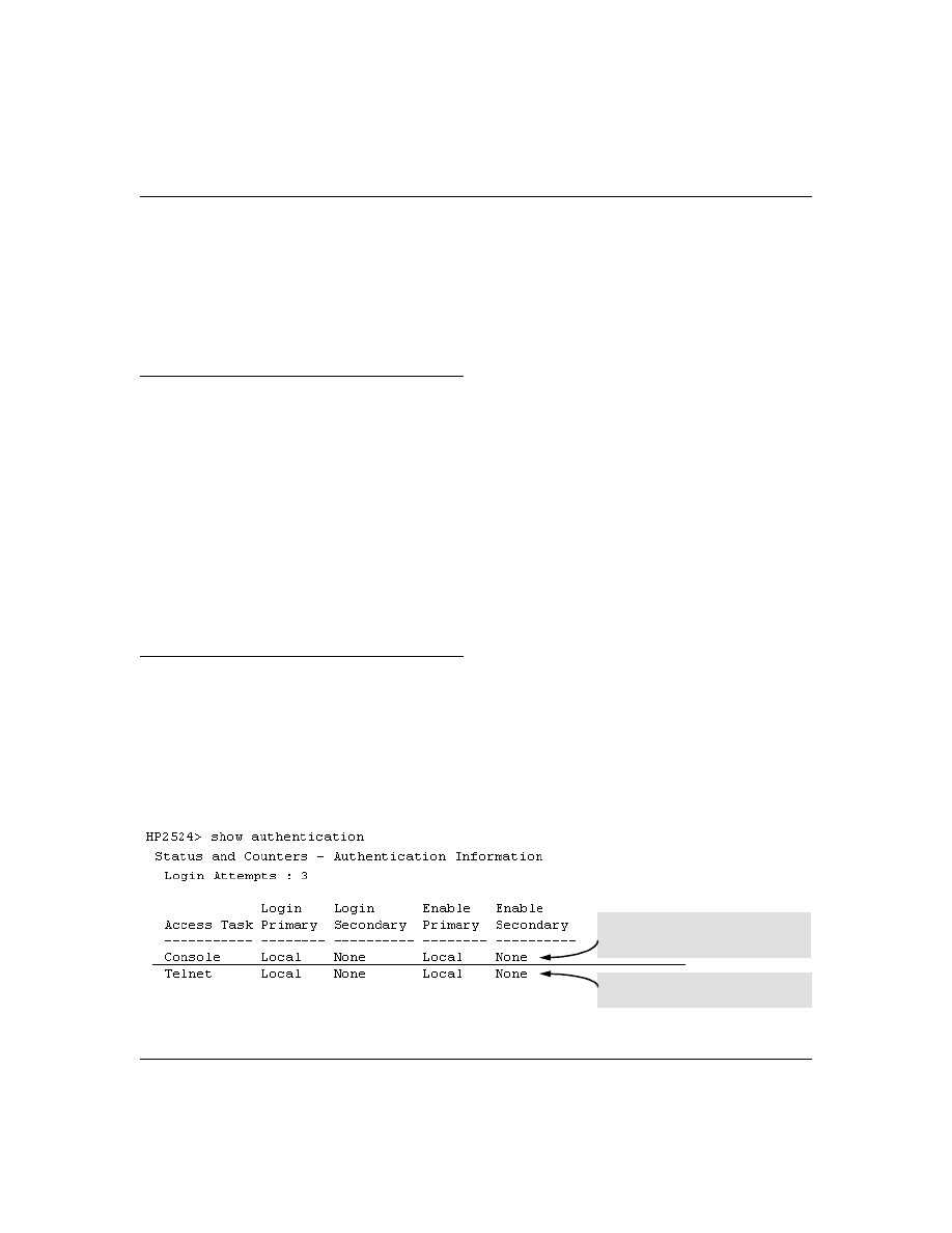
Viewing the Switch’s Current Authentication Configuration
This command lists the number of login attempts the switch allows in a single login session, and the
primary/secondary access methods configured for each type of access.
Syntax:
show authentication
This example shows the default authentication configuration.
Figure 2. Example Listing of the Switch’s Authentication Configuration
show authentication
below
show tacacs
page 15
aaa authentication
console
Telnet
num-attempts <1..10>
tacacs-server
host <ip addr>
key
page 22
timeout <1 ..255>
page 22
Configuration for login and enable access
to the switch through the switch console
port.
Configuration for login and enable access
to the switch through Telnet.
15
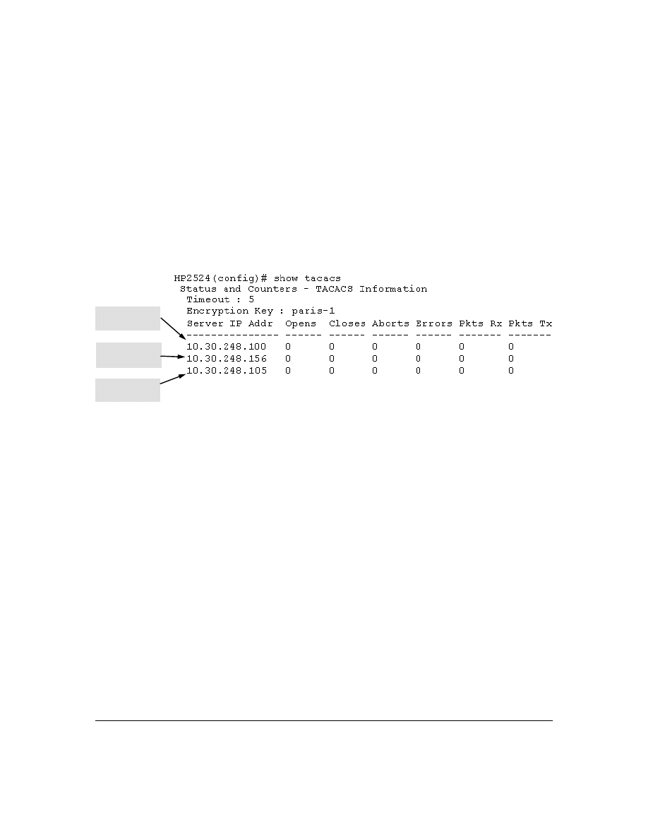
Viewing the Switch’s Current TACACS+ Server Contact Configuration
This command lists the timeout period, encryption key, and the IP addresses of the first-choice and
backup TACACS+ servers the switch can contact.
Syntax:
show tacacs
For example, if the switch was configured for a first-choice and two backup TACACS+ server
addresses, the default timeout period, and
paris-1
for a (global) encryption key,
show tacacs
would
produce a listing similar to the following:
Figure 3. Example of the Switch’s TACACS+ Configuration Listing
Configuring the Switch’s Authentication Methods
The
aaa authentication
command configures the access control for console port and Telnet access to
the switch. That is, for both access methods, aaa authentication specifies whether to use a TACACS+
server or the switch’s local authentication, or (for some secondary scenarios) no authentication
(meaning that if the primary method fails, authentication is denied). This command also reconfigures
the number of access attempts to allow in a session if the first attempt uses an incorrect username/
password pair.
Syntax:
aaa authentication <console | telnet> <enable | login> <local | tacacs> <local | none>
aaa authentication num-attempts <1. . 10>
First-Choice
TACACS+ Server
Second-Choice
TACACS+ Server
Third-Choice
TACACS+ Server

16
Table 1. AAA Authentication Parameters
As shown in the following table, login and enable access is always available locally through a direct
terminal connection to the switch’s console port. However, for Telnet access, you can configure
TACACS+ to deny access if a TACACS+ server goes down or otherwise becomes unavailable to the
switch.
Name
Default
Range
Function
console
- or -
telnet
n/a
n/a
Specifies whether the command is configuring authentication for the console
port or Telnet access method for the switch.
enable
- or -
login
n/a
n/a
Specifies the privilege level for the access method being configured.
login: Operator (read-only) privileges
enable: Manager (read-write) privileges
local
- or -
tacacs
local
n/a
Specifies the primary method of authentication for the access method being
configured.
local: Use the username/password pair configured locally in the switch for
the privilege level being configured
tacacs: Use a TACACS+ server.
local
- or -
none
none
n/a
Specifies the secondary (backup) type of authentication being configured.
local: The username/password pair configured locally in the switch for the
privilege level being configured
none: No secondary type of authentication for the specified
method/privilege path. (Available only if the primary method of
authentication for the access being configured is local.)
Note: If you do not specify this parameter in the command line, the switch
automatically assigns the secondary method as follows:
• If the primary method is tacacs, the only secondary method is local.
• If the primary method is local, the default secondary method is none.
num-attempts
3
1 - 10
In a given session, specifies how many tries at entering the correct username/
password pair are allowed before access is denied and the session terminated.

17
Table 2. Primary/Secondary Authentication Table
Access Method and
Privilege Level
Authentication Options
Effect on Access Attempts
Primary
Secondary
Console — Login
local
none*
Local username/password access only.
tacacs
local
If Tacacs+ server unavailable, uses local username/password access.
Console — Enable
local
none*
Local username/password access only.
tacacs
local
If Tacacs+ server unavailable, uses local username/password access.
Telnet — Login
local
none*
Local username/password access only.
tacacs
local
If Tacacs+ server unavailable, uses local username/password access.
tacacs
none
If Tacacs+ server unavailable, denies access.
Telnet — Enable
local
none*
Local username/password access only.
tacacs
local
If Tacacs+ server unavailable, uses local username/password access.
tacacs
none
If Tacacs+ server unavailable, denies access.
*When "local" is the primary option, you can also select "local" as the secondary option. However, in this case, a secondary
"local" is meaningless because the switch has only one local level of username/password protection.

18
For example, here is a set of access options and the corresponding commands to configure them:
Console Login (Operator, or Read-Only) Access:
Primary using TACACS+ server.
Secondary using Local.
HP2512(config)#
aaa authentication
console login tacacs
local
Console Login
(Operator, or Read-
Only Access)
Primary
Secondary
Console Enable (Manager, or Read/Write) Access:
Primary using TACACS+ server.
Secondary using Local.
HP2512(config)#
aaa authentication
console enable
tacacs
local
Console Enable
(Manager, or Read/
Write Access)
Primary
Secondary
Telnet Login (Operator, or Read-Only) Access:
Primary using TACACS+ server.
Secondary using Local
.
HP2512(config)# aaa authenticationtelnet
login tacacs local
Telnet Login
(Operator, or Read-
Only Access)
Primary
Secondary
Telnet Enable (Manager, or Read/Write) Access:
Primary using TACACS+ server.
Secondary using Local.
HP2512(config)#
aaa authentication
telnet
enable
tacacs
local
Telnet Enable
(Manager, or Read/
Write Access)
Primary
Secondary
Deny Access and Close the Session After Failure of Two Consecutive Username/Password Pairs:
HP2512(config)#
aaa authentication
num-attempts
2
Attempt Limit

19
Configuring the Switch’s TACACS+ Server Access
The tacacs-server command configures these parameters:
■
The host IP address(es)
for up to three TACACS+ servers; one first-choice and up to two
backups. Designating backup servers provides for a continuation of authentication services
in case the switch is unable to contact the first-choice server.
■
An optional encryption key.
This key helps to improve security, and must match the
encryption key used in your TACACS+ server application. In some applications, the term
"secret key" or "secret" may be used instead of "encryption key". If you need only one
encryption key for the switch to use in all attempts to authenticate through a TACACS+
server, configure a global key. However, if the switch is configured to access multiple
TACACS+ servers having different encryption keys, you can configure the switch to use
different encryption keys for different TACACS+ servers.
■
The timeout value
in seconds for attempts to contact a TACACS+ server. If the switch sends
an authentication request, but does not receive a response within the period specified by the
timeout value, the switch resends the request to the next server in its Server IP Addr list, if
any. If the switch still fails to receive a response from any TACACS+ server, it reverts to
whatever secondary authentication method was configured using the
aaa authentication
command (local or none; see “Configuring the Switch’s Authentication Methods” on page 15.)
Syntax:
tacacs-server host <ip-addr>
[key <key-string>]
Adds a TACACS+ server and optionally
assigns a server-specific encryption key.
[no] tacacs-server host <ip-addr>
Removes a TACACS+ server assignment
(encluding its encryption key, if any)
.
tacacs-server key <key-string>
Enters the optional global encryption key.
[no]
tacacs-server key
Removes the optional global encryption
key. (Does not affect any server-specific
encryption key assignments.)
tacacs-server timeout <1 . . 255>
Changes the wait period for a TACACS
server response. (Default: 5 seconds.)

20
Name
Default
Range
host <ip-addr> [key <key-string>
none
n/a
Specifies the IP address of a device running a TACACS+ server application. Optionally, can also specify the unique, per-
server encryption key to use when each assigned server has its own, unique key. For more on the encryption key, see
“Using the Encryption Key” on page 24 and the documentation provided with your TACACS+ server application.
You can enter up to three IP addresses; one first-choice and two (optional) backups (one second-choice and one third-
choice).
Use show tacacs to view the current IP address list.
If the first-choice TACACS+ server fails to respond to a request, the switch tries the second address, if any, in the show
tacacs list. If the second address also fails, then the switch tries the third address, if any.
(See figure 3, "Example of the Switch’s TACACS+ Configuration Listing" on page 15.)
The priority (first-choice, second-choice, and third-choice) of a TACACS+ server in the switch’s TACACS+ configuration
depends on the order in which you enter the server IP addresses:
1.When there are no TACACS+ servers configured, entering a server IP address makes that server the first-choice
TACACS+ server.
2.When there is one TACACS+ serves already configured, entering another server IP address makes that server the
second-choice (backup) TACACS+ server.
3.When there are two TACACS+ servers already configured, entering another server IP address makes that server
the third-choice (backup) TACACS+ server.
• The above position assignments are fixed. Thus, if you remove one server and replace it with another, the new server
assumes the priority position that the removed server had. For example, suppose you configured three servers, A, B,
and C, configured in order:
First-Choice:
A
Second-Choice:
B
Third-Choice: C
• If you removed server B and then entered server X, the TACACS+ server order of priority would be:
First-Choice:
A
Second-Choice:
X
Third-Choice: C
• If there are two or more vacant slots in the TACACS+ server priority list and you enter a new IP address, the new
address will take the vacant slot with the highest priority. Thus, if A, B, and C are configured as above and you (1)
remove A and B, and (2) enter X and Y (in that order), then the new TACACS+ server priority list would be X, Y, and C.
• The easiest way to change the order of the TACACS+ servers in the priority list is to remove all server addresses in
the list and then re-enter them in order, with the new first-choice server address first, and so on.
To add a new address to the list when there are already three addresses present, you must first remove one of the
currently listed addresses.
See also “General Authentication Process Using a TACACS+ Server” on page 23.
key <key-string>
none (null) n/a
Specifies the optional, global "encryption key" that is also assigned in the TACACS+ server(s) that the switch will access
for authentication. This option is subordinate to any "per-server" encryption keys you assign, and applies only to accessing
TACACS+ servers for which you have not given the switch a "per-server" key. (See the host <ip-addr> [key <key-string>
entry at the beginning of this table.)
For more on the encryption key, see “Using the Encryption Key” on page 24 and the documentation provided with your
TACACS+ server application.
21
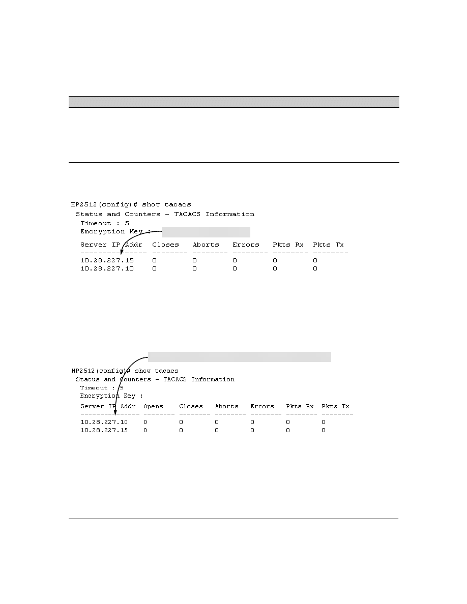
Adding, Removing, or Changing the Priority of a TACACS+ Server.
Suppose that the switch
was already configured to use TACACS+ servers at 10.28.227.10 and 10.28.227.15. In this case,
10.28.227.15 was entered first, and so is listed as the first-choice server:
Figure 4. Example of the Switch with Two TACACS+ Server Addresses Configured
To move the "first-choice" status from the "15" server to the "10" server, use the
no tacacs-server host <ip-
addr>
command to delete both servers, then use
tacacs-server host <ip-addr>
to re-enter the "10" server
first, then the "15" server.
The servers would then be listed with the new "first-choice" server, that is:
Figure 5.
Example of the Switch After Assigning a Different "First-Choice" Server
To remove the 10.28.227.15 device as a TACACS+ server, you would use this command:
HP2512(config)# no tacacs-server host 10.28.227.15
timeout <1. . 255>
5 sec
1 - 255 sec
Specifies how long the switch waits for a TACACS+ server to respond to an authentication request. If the switch does
not detect a response within the timeout period, it initiates a new request to the next TACACS+ server in the list. If all
TACACS+ servers in the list fail to respond within the timeout period, the switch uses either local authentication (if
configured) or denies access (if none configured for local authentication).
Name
Default
Range
First-Choice TACACS+ Server
The "10" server is now the "first-choice" TACACS+ authentication device.

22
Configuring an Encryption Key.
Use an encryption key in the switch if the switch will be
requesting authentication from a TACACS+ server that also uses an encryption key. (If the server
expects a key, but the switch either does not provide one, or provides an incorrect key, then the
authentication attempt will fail.) Use a global encryption key
if the same key applies to all TACACS+
servers the switch may use for authentication attempts. Use a per-server encryption key if different
servers the switch may use will have different keys. (For more details on encryption keys, see “Using
the Encryption Key” on page 24.)
To configure
westside
as a global encryption key:
HP2512(config) tacacs-server key westside
To configure
westside
as a per-server encryption key:
HP2512(config)tacacs-server host 10.28.227.63 key westside
An encryption key can contain up to 100 characters, without spaces, and is likely to be case-sensitive
in most TACACS+ server applications.
To delete a global encryption key from the switch, use this command:
HP2512(config)# no tacacs-server key
To delete a per-server encryption key in the switch, re-enter the tacacs-server host command without
the key parameter. For example, if you have
westside
configured as the encryption key for a TACACS+
server with the IP address of 10.28.227.104 and you wanted to eliminate the key, you would use this
command:
HP2512(config)# tacacs-server host 10.28.227.104
N o t e
The show tacacs command lists the global encryption key, if configured. However, to view any
configured per-server encryption keys, you must use
show config running
.
Configuring the Timeout Period.
The timeout period specifies how long the switch waits for a
response to an authentication request from a TACACS+ server before either sending a new authen-
tication request to the next server in the switch’s Server IP Address list or using the local authenti-
cation option. For example, to change the timeout period from 5 seconds (the default) to 3 seconds:
HP2512(config)# tacacs-server timeout 3
23
How Authentication Operates
General Authentication Process Using a TACACS+ Server
Authentication through a TACACS+ server operates generally as described below. For specific
operating details, refer to the documentation you received with your TACACS+ server application.
Figure 6. Using a TACACS+ Server for Authentication
Using figure 6, above, after either switch detects an operator’s logon request from a remote or directly
connected terminal, the following events occur:
1.
The switch queries the first-choice TACACS+ server for authentication of the request.
•
If the switch does not receive a response from the first-choice TACACS+ server, it
attempts to query a secondary server. If the switch does not receive a response from any
TACACS+ server, then it uses its own local username/password pairs to authenticate the
logon request. (See "Local Authentication Process", on page 24.)
•
If a TACACS+ server recognizes the switch, it forwards a username prompt to the
requesting terminal via the switch.
2.
When the requesting terminal responds to the prompt with a username, the switch forwards it
to the TACACS+ server.
3.
After the server receives the username input, the requesting terminal receives a password
prompt from the server via the switch.
4.
When the requesting terminal responds to the prompt with a password, the switch forwards it
to the TACACS+ server and one of the following actions occurs:
Series 2500 Switch
Configured for
TACACS+ Operation
First-Choice
TACACS+ Server
B
Series 2500 Switch
Configured for
TACACS+ Operation
Terminal "A" Directly Accessing This
Switch Via Switch’s Console Port
Terminal "B" Remotely Accessing
This Switch Via Telnet
A
Second-Choice
TACACS+ Server
(Optional)
Third-Choice
TACACS+ Server
(Optional)

24
•
If the username/password pair received from the requesting terminal matches a user-
name/password pair previously stored in the server, then the server passes access
permission through the switch to the terminal.
•
If the username/password pair entered at the requesting terminal does not match a
username/password pair previously stored in the server, access is denied. In this case,
the terminal is again prompted to enter a username and repeat steps 2 through 4. In the
default configuration, the switch allows up to three attempts to authenticate a login
session. If the requesting terminal exhausts the attempt limit without a successful
TACACS+ authentication, the login session is terminated and the operator at the
requesting terminal must initiate a new session before trying again.
Local Authentication Process
When the switch is configured to use TACACS+, it reverts to local authentication only if one of these
two conditions exists:
■
"Local" is the authentication option for the access method being used.
■
The switch has been configured to query a TACACS+ server for an authentication request,
but has not received a response
(For a listing of authentication options, see Table 2 on page 17.)
For local authentication, the switch uses the operator-level and manager-level username/password
set(s) previously configured locally on the switch. (These are the usernames and passwords you can
configure using the CLI password command, the web browser interface, or the menu interface—
which enables only local password configuration).
■
If the operator at the requesting terminal correctly enters the username/password pair for
either access level, access is granted.
■
If the username/password pair entered at the requesting terminal does not match either
username/password pair previously configured locally in the switch, access is denied. In this
case, the terminal is again prompted to enter a username/password pair. In the default
configuration, the switch allows up to three attempts. If the requesting terminal exhausts the
attempt limit without a successful authentication, the login session is terminated and the
operator at the requesting terminal must initiate a new session before trying again.
Using the Encryption Key
General Operation
When used, the encryption key (sometimes termed "key", "secret key", or "secret") helps to prevent
unauthorized intruders on the network from reading username and password information in
TACACS+ packets moving between the switch and a TACACS+ server. At the TACACS+ server, a key
may include both of the following:

25
■
Global key:
A general key assignment in the TACACS+ server application that applies to all
TACACS-aware devices for which an individual key has not been configured.
■
Individual key:
A unique key assignment in the TACACS+ server application that applies
to a specific TACACS-aware device.
N o t e
Configure a key in the switch only if the TACACS+ server application has this exact same key
configured for the switch. That is, if the key parameter in switch "X" does not exactly match the key
setting for switch "X" in the TACACS+ server application, then communication between the switch
and the TACACS+ server will fail and authentication results will be unpredictable.
Thus, on the TACACS+ server side, you have a choice as to how to implement a key. On the switch
side, it is necessary only to enter the key parameter so that it exactly matches its counterpart in the
server. For information on how to configure a general or individual key in the TACACS+ server, refer
to the documentation you received with the application.
Encryption Options in the Switch
When configured, the encryption key causes the switch to encrypt the TACACS+ packets it sends to
the server. When left at "null", the TACACS+ packets are sent in clear text. The encryption key (or
just "key") you configure in the switch must be identical to the encryption key configured in the
corresponding TACACS+ server. If the key is the same for all TACACS+ servers the switch will use
for authentication, then configure a global key in the switch. If the key is different for one or more
of these servers, use "per-server" keys in the switch. (If you configure both a global key and one or
more per-server keys, the per-server keys will override the global key for the specified servers.)
For example, you would use the next command to configure a global encryption key in the switch to
match a key entered as
north40campus
in two target TACACS+ servers. (That is, both servers use the
same key for your switch.) Note that you do not need the server IP addresses to configure a global
key in the switch:
HP2512(config)# tacacs-server key north40campus
Suppose that you subsequently add a third TACACS+ server (with an IP address of 10.28.227.87) that
has
south10campus
for an encryption key. Because this key is different than the one used for the two
servers in the previous example, you will need to assign a per-server key in the switch that applies
only to the designated server:
HP2512(config)# tacacs-server host 10.28.227.87 key south10campus
With both of the above keys configured in the switch, the
south10campus
key overrides the
north40campus
key only when the switch tries to access the TACACS+ server having the 10.28.227.87 address.

26
Controlling Web Browser Interface Access When Using TACACS+
Authentication
In release F.02.xx, configuring the switch for TACACS+ authentication does not affect web browser
interface access. To prevent unauthorized access through the web browser interface, do one or more
of the following:
■
Configure local authentication (a Manager user name and password and, optionally, an
Operator user name and password) on the switch.
■
Configure the switch’s Authorized IP Manager feature to allow web browser access only from
authorized management stations. (The Authorized IP Manager feature does not interfere with
TACACS+ operation.)
■
Disable web browser access to the switch.
Messages
The switch generates the CLI messages listed below. However, you may see other messages
generated in your TACACS+ server application. For information on such messages, refer to the
documentation you received with the application.
CLI Message
Meaning
Connecting to Tacacs server
The switch is attempting to contact the TACACS+ server identified in the switch’s
tacacs-server configuration as the first-choice (or only) TACACS+ server.
Connecting to secondary Tacacs
server
The switch was not able to contact the first-choice TACACS+ server, and is now
attempting to contact the next (secondary) TACACS+ server identified in the switch’s
tacacs-server configuration.
Invalid password
The system does not recognize the username or the password or both. Depending on
the authentication method (tacacs or local), either the TACACS+ server application
did not recognize the username/password pair or the username/password pair did
not match the username/password pair configured in the switch.
No Tacacs servers responding
The switch has not been able to contact any designated TACACS+ servers. If this
message is followed by the Username prompt, the switch is attempting local authen-
tication.
Not legal combination of authen-
tication methods
For console access, if you select tacacs as the primary authentication method, you
must select local as the secondary authentication method. This prevents you from
being locked out of the switch if all designated TACACS+ servers are inaccessible to
the switch.
Record already exists
When resulting from a tacacs-server host <ip addr> command, indicates an attempt
to enter a duplicate TACACS+ server IP address.

27
Operating Notes
■
If you configure Authorized IP Managers on the switch, it is not necessary to include any
devices used as TACACS+ servers in the authorized manager list. That is, TACACS+ operates
regardless of any Authorized IP Manager configuration.
■
When TACACS+ is not enabled on the switch—or when the switch’s only designated
TACACS+ servers are not accessible— setting a local Operator password without also
setting a local Manager password does not protect the switch from manager-level access
by unauthorized persons
.)
Troubleshooting TACACS+ Operation
All Users Are Locked Out of Access to the Switch.
If the switch is functioning properly, but no
username/password pairs result in console or Telnet access to the switch, the problem may be due
to how the TACACS+ server and/or the switch are configured. Use one of the following methods to
recover:
■
Access the TACACS+ server application and adjust or remove the configuration parameters
controlling access to the switch.
■
If the above method does not work, try eliminating configuration changes in the switch that
have not been saved to flash (boot-up configuration) by causing the switch to reboot from
the boot-up configuration (which includes only the configuration changes made prior to the
last
write memory
command.) If you did not use
write memory
to save the authentication
configuration to flash, then pressing the Reset button or cycling the power reboots the switch
with the boot-up configuration.
■
Disconnect the switch from network access to any TACACS+ servers and then log in to the
switch using either Telnet or direct console port access. Because the switch cannot access
a TACACS+ server, it will default to local authentication. You can then use the switch’s local
Operator or Manager username/password pair to log on.
■
As a last resort, use the Clear/Reset button combination to reset the switch to its factory
default boot-up configuration. Taking this step means you will have to reconfigure the switch
to return it to operation in your network.
No Communication Between the Switch and the TACACS+ Server Application.
If the
switch can access the server device (that is, it can
ping
the server), then a configuration error may be
the problem. Some possiblities include:
■
The server IP address configured with the switch’s tacacs-server host command may not be
correct. (Use the switch’s
show tacacs-server
command to list the TACACS+ server IP address.)

28
■
The encryption key configured in the server does not match the encryption key configured
in the switch (by using the
tacacs-server key
command). Verify the key in the server and
compare it to the key configured in the switch. (Use
show tacacs-server
to list the key.)
■
The accessible TACACS+ servers are not configured to provide service to the switch.
Access Is Denied Even Though the Username/Password Pair Is Correct.
Some reasons for
denial include the following parameters controlled by your TACACS+ server application:
■
The account has expired.
■
The access attempt is through a port that is not allowed for the account.
■
The time quota for the account has been exhausted.
■
The time credit for the account has expired.
■
The access attempt is outside of the timeframe allowed for the account.
■
The allowed number of concurrent logins for the account has been exceeded
For more help, refer to the documentation provided with your TACACS+ server application.
Unknown Users Allowed to Login to the Switch.
Your TACACS+ application may be configured
to allow access to unknown users by assigning them the privileges included in a default user profile.
Refer to the documentation provided with your TACACS+ server application.
System Allows Fewer Login Attempts than Specified in the Switch Configuration.
Your
TACACS+ server application may be configured to allow fewer login attempts than you have
configured in the switch with the
aaa authentication num-attempts
command.

29
CDP
CDP Features
Introduction
In the Series 2500 switches, CDP-v1 (Cisco Discovery Protocol, version 1) provides data that aids
SNMP-based network mapping utilities designed to discover devices running CDP in a network. To
make this data available, the switch transmits information about itself via CDP packets to adjacent
devices, and also receives and stores information about adjacent devices running CDP. This enables
each CDP device to receive and maintain identity data on each of its CDP neighbors and pass this
information off to an SNMP utility designed to query the CDP area of the device’s MIB.
N o t e
To take advantage of CDP in the Series 2500 switches, you should have a working knowledge of SNMP
operation and an SNMP utility capable of polling the switches for CDP data. HP’s implementation of
CDP places specific data into the switch’s Management Information Base (MIB). However, retrieval
of this data for network mapping is dependent on the operation of your SNMP utility. Refer to the
documentation provided with the utility.
An SNMP utility can progressively discover CDP devices in a network by:
1.
Reading a given device’s CDP Neighbor table (in the Management Information Base, or MIB) to
learn about other, neighbor CDP devices
2.
Using the information learned in step 1 to go to and read the neighbor devices’ CDP Neighbors
tables to learn about additional CDP devices, and so on
Feature
Default
Menu
CLI
Web
view the switch’s CDP configuration
n/a
—
page 34
—
view the switch’s CDP Neighbors table
n/a
—
page 35
—
clear (reset) the CDP Neighbors table
n/a
—
page 36
—
enable or disable CDP on the switch
enabled
—
page 37
—
enable or disable CDP operation on an individual port
enabled
—
page 37
—
change the transmit interval for the switch’s CDP packets
60 seconds
—
page 38
—
change the hold time (time-to-live for CDP packets the switch
generates)
180 seconds
—
page 38
—
30
This section describes CDP operation in the Series 2500 switches. For information on how to use an
SNMP utility to retrieve the CDP information from the switch’s CDP Neighbors table (in the switch’s
MIB), refer to the documentation provided with the particular SNMP utility. For information on the
object identifiers in the CDP MIB, see “CDP Neighbor Data and MIB Objects” on page 40.
CDP Terminology
■
CDP Device:
A switch, server, router, workstation, or other device running CDP.
■
CDP-Aware:
A device that has CDP in its operating code (with CDP either enabled or
disabled in that device).
■
CDP-Disabled
: A CDP-aware device on which CDP is currently disabled.
■
Non-CDP Device:
A device that does not have CDP in its operating code.
■
CDP Neighbor:
A CDP device that is either directly connected to another CDP device or
connected to that device by a non-CDP device, such as some hubs.
General CDP Operation
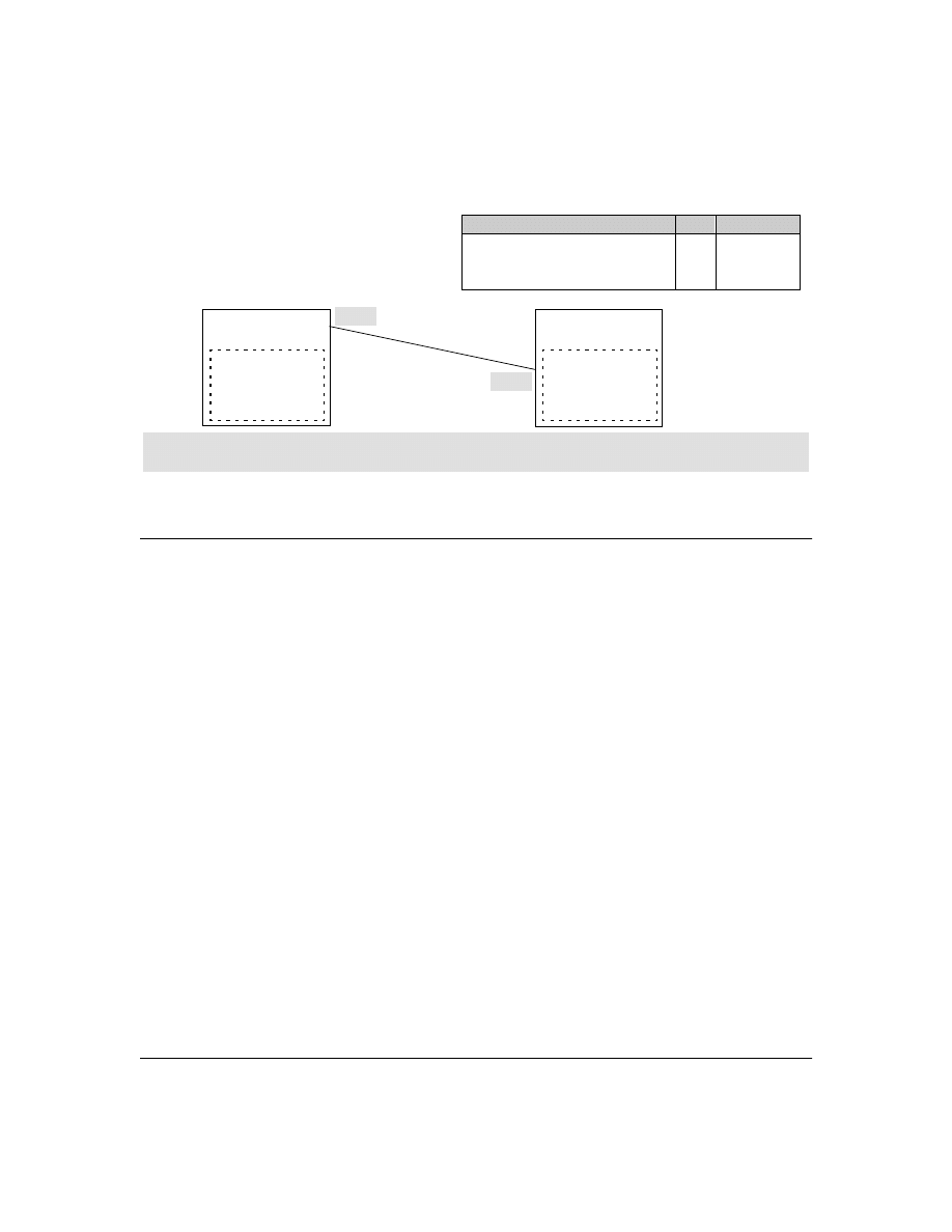
The switch stores information about adjacent CDP devices in a CDP Neighbors table. For example:
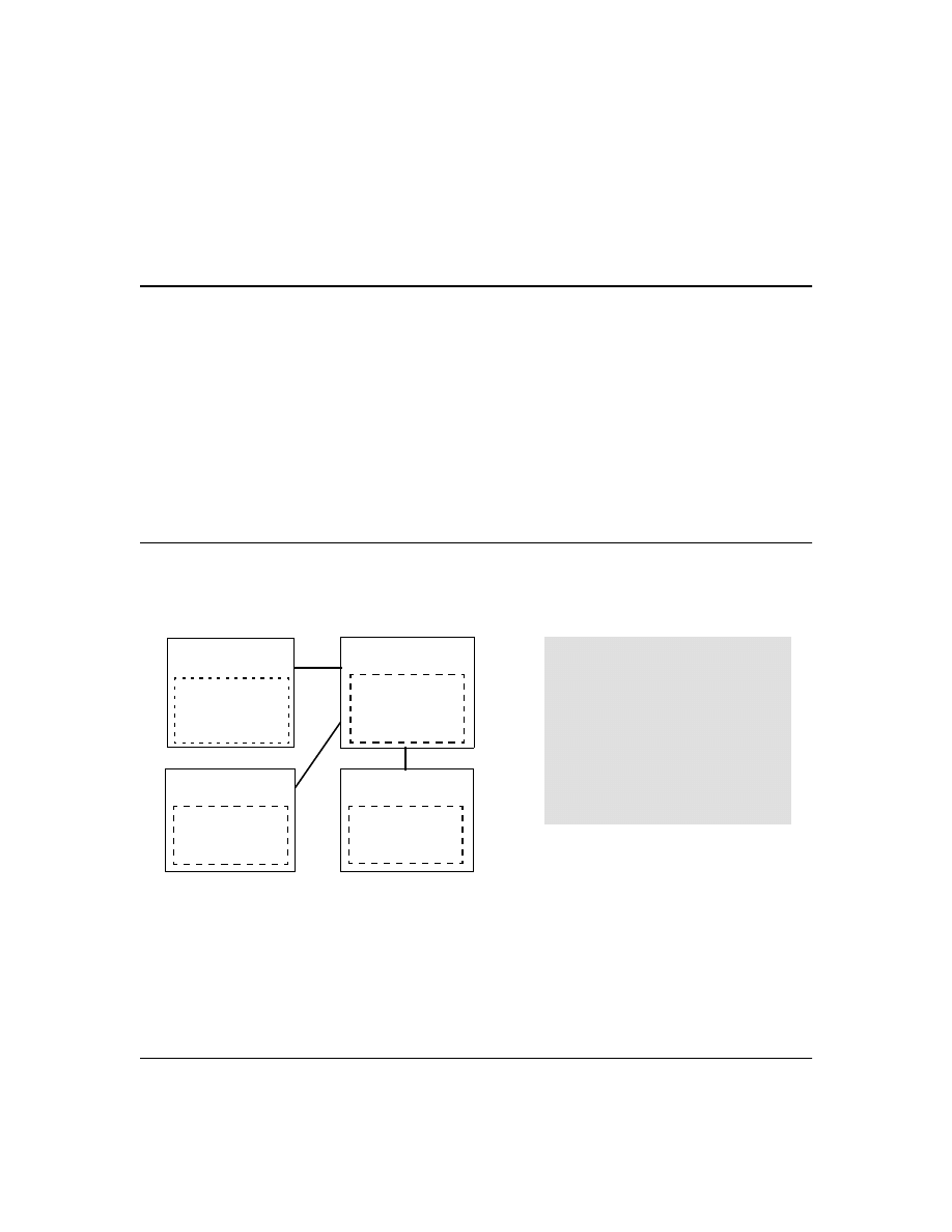
Figure 7. Example of How Series 2500 Switches Store Data on Neighbor CDP Devices
Outgoing Packets
A Series 2500 switch running CDP periodically transmits a one-hop CDP packet out each of its ports.
This packet contains data describing the switch and, if the one-hop destination is another device
running CDP, the receiving device stores the sending device’s data in a CDP Neighbors table. The
receiving device also transmits a similar one-hop CDP packet out each of its ports to make itself
Switch "A"
with CDP Running
•
The Neighbors table in switches "A", "B", and "D"
contain information on switch "C" only because
it is the only neighbor for these switches.
•
The Neighbors table in switch "C" contains
information on switches "A", "B", and "D"
because all of these switches are neighbors of
switch "C".
Note: A given switch’s CDP Neighbor table
includes data only on neighbor CDP devices, but
not on that switch itself.
CDP Neighbor Table
Switch "C" data
Switch "B"
with CDP Running
CDP Neighbor Table
Switch "C" data
Switch "C"
with CDP Running
CDP Neighbor Table
Switch "A" data
Switch "B" data
Switch "D" data
Switch "D"
with CDP Running
CDP Neighbor Table
Switch "C" data
31
known to other CDP devices to which it is connected. Thus, each CDP device in the network provides
data on itself to the CDP neighbors to which it is directly connected. However, there are instances
where a packet is forwarded beyond the immediate neighbor, or simply dropped.
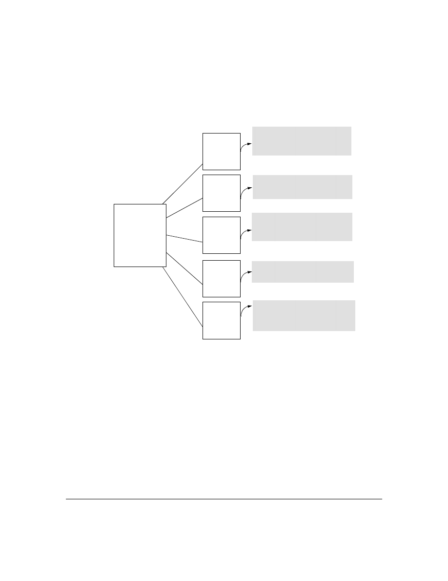
Figure 8. Example of Outgoing CDP Packet Operation
Incoming CDP Packets
When a CDP-enabled Series 2500 switch receives a CDP packet from another CDP device, it enters
that device’s data in the CDP Neighbors table, along with the port number where the data was received
(and does not forward the packet). The switch also periodically purges the table of any entries that
have expired. (The hold time for any data entry in the switch’s CDP Neighbors table is configured in
the device transmitting the CDP packet, and cannot be controlled in the switch receiving the packet.)
The Series 2500 switches purge expired CDP neighbor entries every three seconds.
Non-CDP devices such as some hubs and other devices that do not have CDP capability are
transparent to CDP operation. (Other hubs are CDP-aware, but still forward CDP packets as if they
were transparent to CDP operation. See “CDP-Capable Hubs” on page 42.) However, an intervening
CDP-aware device that is CDP-disabled is not transparent. For example, in figure 9, the CDP neighbor
Switch "A"
Series 2500 Switch
with CDP Running
and Forwarding CDP
Packets to Down-
stream Devices
Switch "B"
CDP-Aware
Switch with
CDP Running
Switch "C"
CDP-Aware
Switch with
CDP Disabled
Router "Y"
With CDP
Disabled or
Nonexistent
Device "Z"
Hub or Other
Non-CDP
Device
Router "X"
With CDP
Running
Accepts, but does not forward CDP
packets describing Switch "A". Also
transmits CDP packets describing itself
(Switch "B") out all ports.
Drops CDP packets describing Switch "A".
Also does not transmit any CDP packets
describing itself (Router "Y").
Forwards CDP packets from Switch "A" out
all ports (except the port receiving the
packets from "A") without any awareness
of CDP operation.
Drops CDP packets describing Switch
"A". Also, does not transmit any CDP
packets describing itself (Switch "C").
Accepts, but does not forward CDP
packets from Switch "A". Also transmits
CDP packets describing itself (Router "X")
out all ports.
32
pairs are as follows: A/1, A/2, A/3, A/B, B/C. Note that "C" and "E" are not neighbors because the
intervening CDP-disabled switch "D" does not forward CDP packets; i.e. is not transparent to CDP
traffic. (For the same reason, switch "E" does not have any CDP neighbors.)
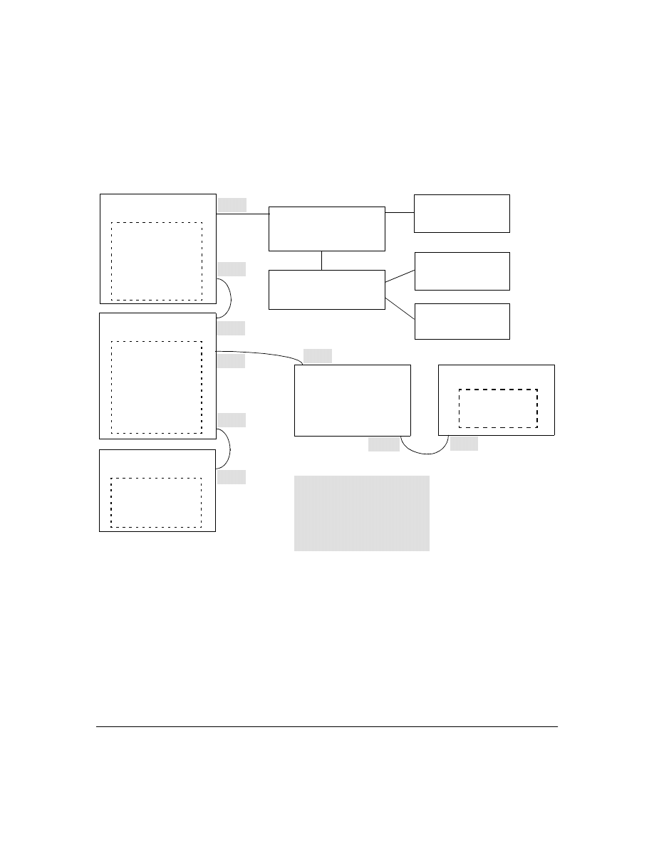
Figure 9. Example of Incoming CDP Packet Results
CDP
Switch "A"
(CDP Running)
CDP Neighbor Table
Port | Data
-------|--------------------
1 | Host 1 data
1 | Host 2 data
1 | Host 3 data
2 | Switch "B" data
CDP
Workstation "1"
(Host 1)
(CDP Running)
Non-CDP Device "X"
Such as a Non-CDP
Hub Switch
CDP
Workstation "2"
(Host 2)
(CDP Running)
Non-CDP Device "Y"
Such as a Non-CDP
Hub or Switch
CDP
Workstation "3"
(Host 3)
(CDP Running)
CDP
Switch "B"
(CDP Running)
CDP Neighbor Table
Port | Data
-------|--------------------
1 | Switch "A" data
5 | Switch "C" data
No CDP data for Switch
"D" because it has dis-
abled CDP operation.
Port 1
Port 1
CDP
Switch "C"
(CDP Running)
CDP Neighbor Table
Port | Data
-------|--------------------
3 | Switch "B" data
Port 3
Port 7
CDP-Disabled
Switch "D"
(No CDP Neighbor Table)
This switch drops CDP packets.
CDP
Switch "E"
(CDP Running)
CDP Neighbor Table
Empty-No CDP
Neighbors
Port 2
Port 3
Port 17
Port 1
"A", "1", "2", and "3" are CDP neighbors.
"A" and "B" are CDP neighbors.
"B" and "C" are CDP neighbors.
Because "D" is CDP-capable, but has
disabled CDP, it is not a CDP neighbor
to either "B" or "E".
Port 5
33
Using the example in figure 9:
The CDP Neighbor table for switches "A" and "B" would appear similar to these:
Switch A:
Switch B:
Figure 10. Example of Viewable CDP Neighbor Table for Switches "A" and "B in Figure 9
Thus, based on the CDP packets it receives, each CDP device maintains a per-port data entry for each
of its neighbors that are running CDP, but not for other CDP devices that are accessible only through
a CDP neighbor. (See the relationship between switches A, B, and C in figure 9.) In other words, a
CDP device will have data on its immediate CDP neighbors (including those reached through a device
that is transparent to CDP), but not to other CDP devices in the network.
Table 3. How Devices Handle Incoming CDP Packets
Non-CDP devices (that is, devices that are not capable of running CDP) are transparent to CDP
operation. However, an intervening CDP-aware device that is CDP-disabled is not transparent. For
example, in figure 9 (page 32), "B", "D", and "E" are not CDP neighbors because "D" (the intervening
CDP-disabled switch) does not forward CDP packets; i.e. is not transparent to CDP traffic. (For the
same reason, switch "E" does not have any CDP neighbors.)
Status of Device Receiving
a CDP Packet
Action of Receiving Device
Running CDP
Stores neighbor data in CDP Neighbor table. Does not forward CDP packet.
CDP Disabled
Drops CDP packet. There is no CDP Neighbor table and no CDP neighbor data is stored.
No CDP Capability
Forwards CDP packet out all ports except the port on which the packet was received.
Router Running CDP
Stores neighbor data in CDP Neighbor table. Does not forward CDP packet.
Router with CDP (1) Disabled
or (2) Not CDP-Capable
Drops CDP packet.
(Note that no CDP devices appear on port 5, which is connected to a device on which CDP is present, but disabled.)

34
Figure 9 (page 32) illustrates how multiple CDP neighbors can appear on a single port. In this case,
switch "A" has three CDP neighbors on port 1 because the intervening devices are not CDP-capable
and simply forward CDP neighbors data out all ports (except the port on which the data was
received).
Configuring CDP on the Switch
On a Series 2500 switch you can:
■
View the switch’s current global and per-port CDP configuration
■
List the current contents of the switch’s CDP Neighbors table (that is, view a listing of the
CDP devices of which the switch is aware)
■
Enable or disable CDP (Default: Enabled)
■
Specify the hold time (CDP packet time-to-live) for CDP data delivered to neighboring CDP
devices. For example, in CDP switch "A" you can specify the hold time for switch "A" entries
in the CDP Neighbor tables of other CDP devices. (Default: 180 seconds)
■
Specify the transmission interval for CDP packets. (Default: 60 seconds)
CLI Commands Described in this Section
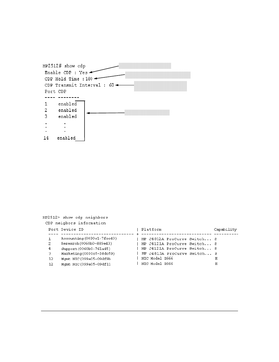
Viewing the Switch’s Current CDP Configuration
This command lists the switch’s global and per-port CDP configuration. (In the factory default
configuration, the switch runs CDP on all ports with a hold time of 180 seconds and a transmit interval
of 60 seconds.)
Syntax:
show cdp
This example shows the default CDP configuration.
show CDP
below
show CDP neighbors
page 35
cdp clear
page 36
[no] cdp run
page 37
[no] cdp enable
page 37
cdp holdtime
page 38
cdp timer
page 38
35
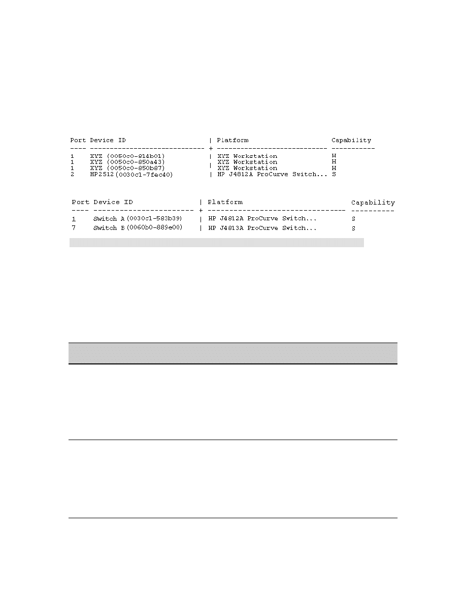
Viewing the Current Contents of the Switch’s CDP Neighbors Table
This command lists the neighboring CDP devices the switch has detected. Devices are listed by the
port on which they were detected. The entry for a specific device includes a subset of the information
collected from the device’s CDP packet. (For more on this topic, see “CDP Neighbor Data and MIB
Objects” on page 40.)
Syntax:
show cdp neigbors
This example lists six CDP devices (four switches and two workstations) that the switch has detected
by receiving their CDP packets.
Figure 11. Example of CDP Neighbors Table Listing
CDP Enable/Disable on the Switch
Packet Hold Time in CDP Neighbor Table
Interval for Transmitting Outbound
CDP Packets on All Ports
Per-Port CDP Enable/Disable
36
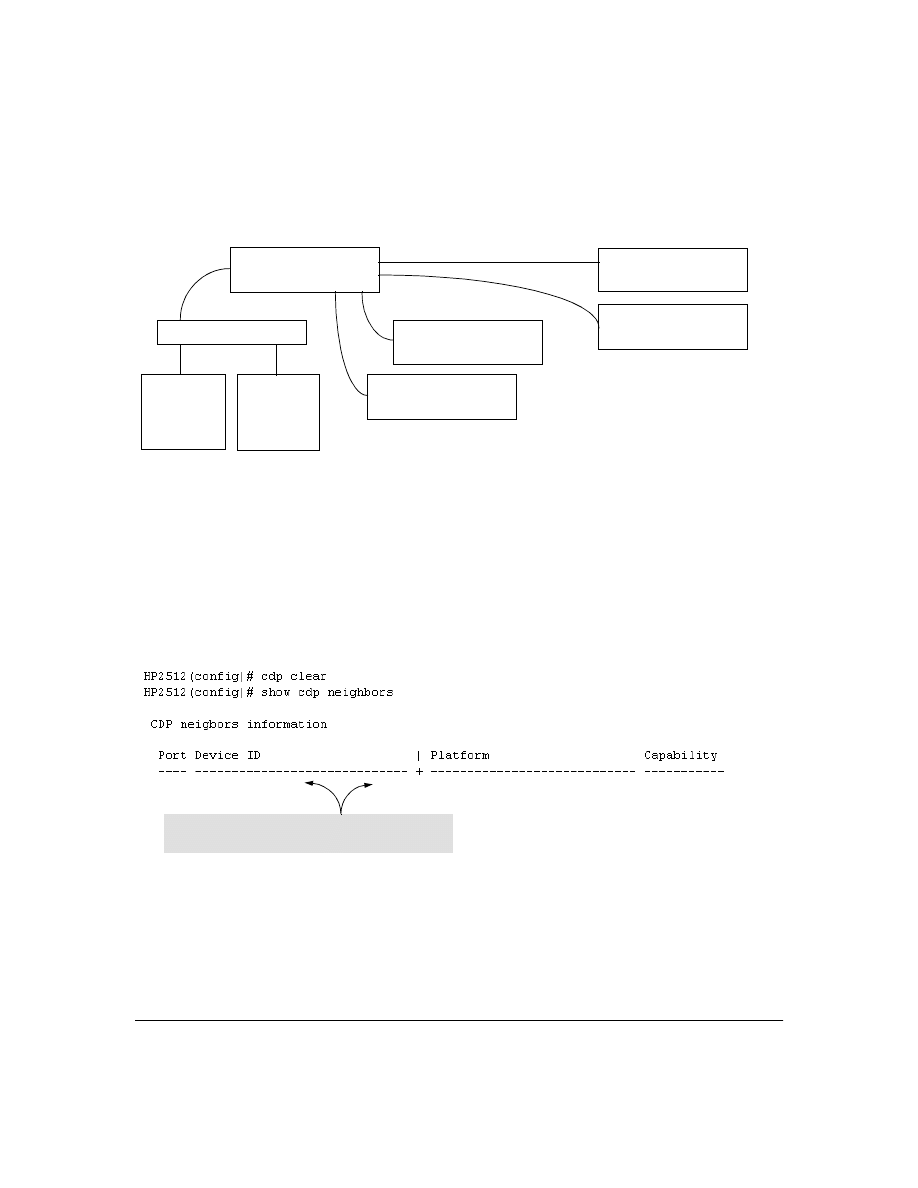
Figure 12 illustrates a topology of CDP-enabled devices for the CDP Neighbors table listing in figure
11.
Figure 12. Example of CDP-Enabled Devices in a Topology for the Listing in Figure 11
Clearing (Resetting) the CDP Neighbors Table
This command removes any records of CDP neighbor devices from the switch’ s CDP MIB objects.
Syntax:
cdp clear
If you execute
cdp clear
and then execute
show cdp
neighbors before the switch receives a CDP packet
from any neighbor device, the displayed table appears empty.
Figure 13. View of the CDP Neighbors Table Immediately After Executing cdp clear
HP 2512
HP Switch 2524
(0030c5-38dc59)
Management
Workstation
099a05-09df9b
HP Switch 4000M
(0060b0-889e43)
HP Switch 4000M
(0060b0-761a45)
HP Switch 2512
(0030c1-7fcc40)
Management
Workstation
099a05-09df11
Non-CDP-Capaable Hub
Note that the table will again list entries after the switch
recives new CDP packets from neighboring CDP devices.

37
Configuring CDP Operation
Enabling or Disabling CDP Operation on the Switch.
Enabling CDP operation (the default) on
the switch causes the switch to:
■
Transmit CDP packets describing itself to other, neighboring CDP devices
■
Add entries to its CDP Neighbors table for any CDP packets it receives from other, neigh-
boring CDP devices
Disabling CDP operation clears the switch’s CDP Neighbors table, prevents the switch from trans-
mitting outbound CDP packets to advertise itself to neighboring CDP devices, and causes the switch
to drop inbound CDP packets from other devices without entering the data in the CDP Neighbors
table.
Syntax:
[no] cdp run
For example, to disable CDP on the switch:
HP2512(config) no cdp run
When CDP is disabled:
■
show cdp neighbors
displays an empty CDP Neighbors table
■
show cdp
displays
Global CDP information
Enable CDP : No
Enabling or Disabling CDP Operation on Individual Ports.
In the factory-default configura-
tion, the switch has all ports enabled and transmitting CDP packets. Disabling CDP on a port prevents
that port from sending outbound CDP packets and causes it to drop inbound CDP packets without
recording their data in the CDP Neighbors table. Suppose, for example, that switches "A" and "B" in
figure 14 are running CDP, and that port 1 on switch "A" is connected to port 5 on switch "B". If you
disable CDP on port 1 of switch "A", then switch "B" will no longer receive CDP packets from switch
"A" and switch "A" will drop the CDP packets it receives from switch "B".
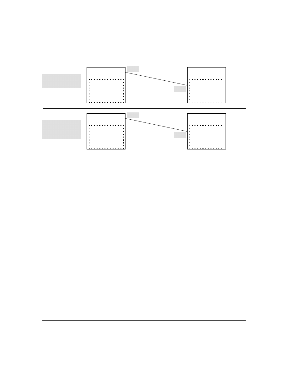
38
Figure 14. Example of Disabling CDP on an Individual Port
(The switch "A" entry in the switch "B" CDP Neighbors table remains until the
cdp holdtime
(time-to-
live; set in switch "A") expires. Until then, the
show cdp neighbors
command continues to list switch "A"
on port 5 of switch "B".)
Syntax:
[no] cdp enable <[ethernet] port-list>
For example, to disable CDP on port 1 of a switch:
HP2512(config) no cdp enable 1
Changing the Transmission Interval for Outbound CDP Packets.
The default interval the
switch uses to transmit CDP packets describing itself to other, neighbor devices is 60 seconds. This
command changes the interval.
Syntax:
cdp timer <5 . . 254>
For example, to reset a switch’s transmit interval for CDP packets to one minute:
HP2512(config) cdp timer 60
Changing the Hold Time (CDP Packet Time-To-Live) for a Switch’s CDP Packet
Information.
The default hold time for the switch’s CDP packet information in the CDP Neighbors
table of another CDP device is 180 seconds (range: 5 - 254). This parameter is controlled in the
transmitting switch, and applies to all outbound CDP packets the switch transmits.
Syntax:
cdp holdtime <5 . . 254>
Switch "A"
CDP Enabled on Port 1
CDP Neighbor Table
Port | Data
------|------------------
1 | Switch "B" data
Switch "B"
CDP Enabled on Port 5
CDP Neighbor Table
Port | Data
------|------------------
5 | Switch "A" data
CDP Enabled on both
ends of the link between
"A" and "B".
Port 1
Port 5
Switch "A"
CDP Disabled on Port 1
CDP Neighbor Table
— Empty for port 1—
Switch "B"
CDP Enabled on Port 5
CDP Neighbor Table
— Empty for Port 5 —
CDP disabled on port 1
of switch "A" (but
enabled on port 5 of
switch "B".
Port 1
Port 5

39
For example, to configure a switch’s outbound CDP packets to live for one minute in the CDP
Neighbors table of neighboring CDP devices:
HP2512(config) cdp holdtime 60
Effect of Spanning Tree (STP) On CDP Packet Transmission
If STP has blocked a port on the switch, that port does not transmit CDP packets. However, the port
still receives CDP packets if the device on the other end of the link has CDP enabled. Thus, for
example, if switch "A" has two ports linked to switch "B" (a CDP neighbor and the STP root device)
and STP blocks traffic on one port and forwards traffic on the other:
■
Switch "A" sends outbound CDP packets on the forwarding link, and the switch "B" CDP
Neighbors table shows switch "A" on only one port.
■
Switch "B" sends outbound CDP packets on both links, and the switch "A" CDP Neighbors
table shows switch "B" on both ports.
To summarize, in a CDP neighbor pair running STP with redundant links, if one of the switches is the
STP root, it transmits CDP packets out all ports connecting the two switches, while the other switch
transmits CDP packets out only the unblocked port. Thus, the STP root switch will appear on multiple
ports in the non-root switches CDP Neighbors table, while the non-root switch will appear on only
one port in the root switch’s CDP Neighbors table.
How CDP Selects the CDP Neighbor’s IP Address When Multiple
VLANs Are Present
When a switch detects a CDP neighbor and there are multiple VLANs configured on the neighbor’s
port, the switch uses the following criteria to determine which IP address to use when listing the
neighbor in the CDP Neighbor table:
1.
If only one VLAN on the neighbor’s port has an IP address, the switch uses that IP address.
2.
If the Primary VLAN on the neighbor’s port has an IP address, the switch uses the neighbor’s
Primary VLAN IP address.
3.
If 1 and 2 do not apply, then the switch determines which VLANs on the neighbor’s port have IP
addresses and uses the IP address of the VLAN with the lowest VID (VLAN Identification
number) in this group.
4.
If a CDP switch does not detect an IP address on the connecting port of a CDP neighbor, then
the loopback IP address is used (127.0.0.1).
For example, in figure 15, port 1 on CDP switch "X" is connected to port 5 on CDP neighbor switch
"Y", with the indicated VLAN configuration on port 5:
40
Figure 15. Example of IP Address Selection when the CDP Neighbor Has Multiple VLANs with IP
Addresses
CDP Neighbor Data and MIB Objects
The switch places the data received from inbound CDP packets into its MIB (Management Informa-
tion Base). This data is available in three ways:
■
Using the switch’s
show cdp neighbors
command to display a subset of Neighbor data
■
Using the
walkmib
command to display a listing of the CDP MIB objects
■
Electronically, using an SNMP utility designed to search the MIB for CDP data
As shown under “Viewing the Current Contents of the Switch’s CDP Neighbors Table” on page 35,
you can list a subset of data for each CDP device currently found in the switch’s CDP Neighbors table.
Table 4, "CDP Neighbors Data", describes the CDP Neighbor data set available in the Series 2500
switches.
Switch "X"
CDP Enabled on Port 1
CDP Neighbor Table
Port | Data
------|------------------
1 | 10.28.227.103
Switch "Y"
CDP Enabled on Port 5
CDP Neighbor Table
Port | Data
------|------------------
5 | Switch "X" data
Port 1
Port 5
VLAN Membership in Port 5 of Switch "Y" VID
IP Address?
DEFAULT_VLAN (Primary VLAN)
1
No
Blue_VLAN
200
10.28.227.103
Red VLAN
300
10.28.227.88
Thus, CDP switch "X" detects CDP switch "Y" on port 1 and shows 10.28.227.103 in its CDP table entry because in CDP switch "Y" the
Primary VLAN does not have an IP address and the Blue_VLAN has a lower VID than the Red_VLAN.
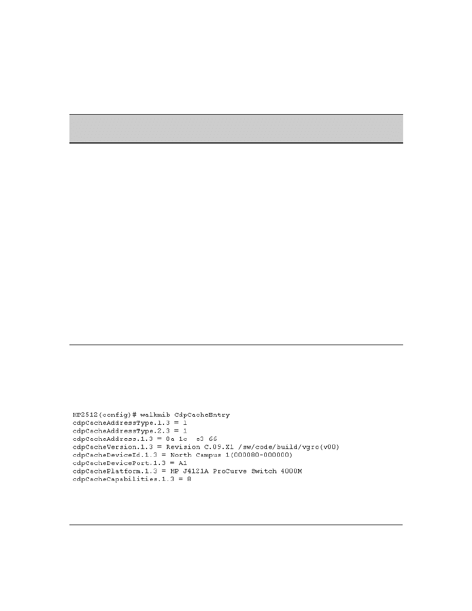
41
Table 4. CDP Neighbors Data
Displaying CDP Neighbor Data.
To display the superset of CDP neighbor data held in the MIB, use
the
walkmib
command.
Syntax:
walkmib <MIB-identifier>
For example, with only one CDP device connected to the switch, you would see a
walkmib
listing
similar to this:
Figure 16. Example of CDP Neighbor Data in the Series 2500 Switch MIB
For the current Series 2500 switch MIB, go to the
technical support
area at
http://www.hp.com/go/hpprocurve
.
CDP Neighbor Data
Displayed
Neighbors
Table
MIB
Address Type
No
Yes
Always "1" (IP address only).
CDP Cache Address
No
Yes
IP address of source device.
Software Version
Yes
Yes
ASCII String
Device Name (ASCII string)
Yes
Yes
In HP ProCurve switches, this is the value configured for
the System Name parameter.
Device MAC Address
Yes
Yes
Included in the Device Name entry.
Destination Port Number
Yes
Yes
On the Series 2500 switch (the receiving device), the
number of the port through which the CDP packet arrived.
Source Port Number
No
Yes
On the source (neighbor) device, the number of the port
through which the CDP packet was sent.
Product Name (ASCII string)
Yes
Yes
Platform name designated by vendor.
Capability Code (Device Type)
Yes
(alpha
character)
Yes
(numeric
character)
1 or R: Router
2: Transparent Bridge
4 or B: Source Route Bridge
8 or S: Switch
16 or H: Host
32 or I: IGMP conditional filtering
64 or r: Repeater

42
Operating Notes
Neighbor Maximum.
The Series 2500 switches support up to 60 neighbors in the CDP Neighbors
table. Even though the switches offer only 12 or 24 ports, multiple CDP devices can be neighbors on
the same port if they are connected to the switch through a non-CDP device.
CDP Version Data.
The Series 2500 switches use CDP-V1, but do not include IP prefix information,
which is a router function; not a switch application.
Port Trunking with CDP.
Where a static or LACP trunk forms the link between the switch and
another CDP device, only one physical link in the trunk is used to transmit outbound CDP packets.
CDP-Capable Hubs.
Some hubs are capable of running CDP, but also forward CDP packets as if the
hub itself were transparent to CDP. Such hubs will appear in the switch’s CDP Neighbor table and
will also maintain a CDP neighbor table similar to that for switches. For more information, refer to
the documentation provided for the specific hub.
Troubleshooting CDP Operation
The switch does not appear in the CDP Neighbors table of an adjacent CDP Device.
This
may be due to any of the following:
■
Either the port connecting the switch to the adjacent device is not a member of an untagged
VLAN or any Untagged VLAN to which the port belongs does not have an IP address.
■
If there is more than one physical path between the switch and the other CDP device and
STP is running on the switch, then STP will block the redundant link(s). In this case, the
switch port on the remaining open link may not be a member of an untagged VLAN, or any
untagged VLANs to which the port belongs may not have an IP address.
■
The adjacent device’s CDP Neighbors table may be full. Refer to the documentation provided
for the adjacent CDP device to determine the table’s capacity, and then view the device’s
Neighbors table to determine whether it is full.
One or more CDP neighbors appear intermittently or not at all in the switch’s CDP
Neighbors table.
This may be caused by more than 60 neighboring devices sending CDP packets to
the switch. Exceeding the 60-neighbor limit can occur, for example, where multiple neighbors are
connected to the switch through non-CDP devices such as many hubs.
The Same CDP Switch or Router Appears on More Than One Port in the CDP Neighbors
Table.
Where CDP is running, a switch or router that is the STP root transmits outbound CDP packets
over all links, including redundant links that STP may be blocking in non-root devices. In this case,
the non-root device shows an entry in its CDP Neighbors table for every port on which it receives a
CDP packet from the root device. See “Effect of Spanning Tree (STP) On CDP Packet Transmission”
on page 39.

43
New Time Synchronization Protocol Options
Using time synchronization ensures a uniform time among interoperating devices. This helps you to
manage and troubleshoot switch operation by attaching meaningful time data to event and error
messages.
Formerly, TimeP was the only time protocol available for time synchronization in Series 2500
switches. Beginning with software release F.02.xx, the switches also offer SNTP (Simple Network
Time Protocol) and a new
timesync
command for changing the time protocol selection (or turning off
time protocol operation).
N o t e s
■
Although you can create and save configurations for both time protocols without conflicts,
the switch allows only one active time protocol at any time.
■
Time synchronization is no longer active in the factory default configuration. You must first
select the desired protocol (default: TimeP), and then enable it.
■
In the factory-default configuration for release F.02.xx and later, the time synchronization
method is set to TimeP, with actual TimeP operation disabled. (In earlier releases, TimeP
was enabled with DHCP for acquiring a TimeP server address).
■
If you configure SNTP operation in the switch, but later download a configuration created
using a pre-F.02.xx version of the software, the SNTP configuration will be replaced by the
non-SNTP time synchronization settings in the downloaded configuration file.
■
In the menu interface, the time protocol parameters have been moved from the "Internet (IP)
Service" screen to the "System Information" screen, and the menu path is now:
2. Switch Configuration...
1. System Information
TimeP Time Synchronization
You can either manually assign the switch to use a TimeP server or use DHCP to assign the TimeP
server. In either case, the switch can get its time synchronization updates from only one, designated
Timep server. This option enhances security by specifying which time server to use.

44
SNTP Time Synchronization
SNTP provides two operating modes:
■
Broadcast Mode:
The switch acquires time updates by accepting the time value from the
first SNTP time broadcast detected. (In this case, the SNTP server must be configured to
broadcast time updates to the network broadcast address. Refer to the documentation
provided with your SNTP server application.) Once the switch detects a particular server, it
ignores time broadcasts from other SNTP servers unless the configurable
Poll Interval
expires
three consecutive times without an update received from the first-detected server.
N o t e
To use Broadcast mode, the switch and the SNTP server must be in the same subnet.
■
Unicast Mode:
The switch requests a time update from the configured SNTP server. (You
can configure one server using the menu interface, or up to three servers using the CLI
sntp
server
command.) This option provides increased security over the Broadcast mode by
specifying which time server to use instead of using the first one detected through a
broadcast.
Overview: Selecting a Time Synchronization Protocol or Turning Off
Time Protocol Operation
General Steps for Running a Time Protocol on the Switch:
1.
Select the time synchronization protocol:
SNTP
or
TimeP
(the default).
2.
Enable the protocol. The choices are:
•
SNTP:
Broadcast
or
Unicast
•
TimeP:
DHCP
or
Manual
3.
Configure the remaining parameters for the time protocol you selected.
The switch retains the parameter settings for both time protocols even if you change from one
protocol to the other. Thus, if you select a time protocol the switch uses the parameters you last
configured for the selected protocol.

45
Note that simply selecting a time synchronization protocol does not enable that protocol on the
switch unless you also enable the protocol itself (step 2, above). For example, in the factory-default
configuration, TimeP is the selected time synchronization method. However, because TimeP is
disabled in the factory-default configuration, no time synchronization protocol is running.
Disabling Time Synchronization
You can use either of the following methods to disable time synchronization without changing the
Timep or SNTP configuration:
■
In the System Information screen of the Menu interface, set the
Time Synch Method
parameter
to
None
, then press
[Enter], then [S] (for
Save
).
■
In the config level of the CLI, execute
no timesync
.
SNTP: Viewing, Selecting, and Configuring
SNTP Features
Feature
Default
Menu
CLI
Web
view the SNTP time synchronization configuration
n/a
page 46
page 49
—
select SNTP as the time synchronization method
timep
page 47
pages 49
ff.
—
disable time synchronization
timep
page 47
page 52
—
enable the SNTP mode (Broadcast, Unicast, or Disabled)
disabled
—
broadcast
n/a
page 47
page 50
—
unicast
n/a
page 47
page 50
—
none/disabled
n/a
page 47
page 53
—
configure an SNTP server address (for Unicast mode only)
none
page 47
pages 50
ff.
—
change the SNTP server version (for Unicast mode only)
3
page 48
page 52
—
change the SNTP poll interval
720 seconds
page 48
page 52
—

46
Table 5. SNTP Parameters
Menu: Viewing and Configuring SNTP
To View, Enable, and Modify SNTP Time Protocol:
1.
From the Main Menu, select:
2. Switch Configuration...
1. System Information
SNTP Parameter Operation
Time Sync
Method
Used to select either SNTP, TIMEP, or None as the time synchronization method.
SNTP Mode
Disabled
The Default. SNTP does not operate, even if specified by the Menu interface Time Sync Method
parameter or the CLI timesync command.
Unicast
Directs the switch to poll a specific server for SNTP time synchronization. Requires at least one server
address.
Broadcast
Directs the switch to acquire its time synchronization from data broadcast by any SNTP server to the
network broadcast address. The switch uses the first server detected and ignores any others.
However, if the Poll Interval expires three times without the switch detecting a time update from the
original server, it the the switch accepts a broadcast time update from the next server it detects.
Poll Interval
(seconds)
In Unicast Mode: Specifies how often the switch polls the designated SNTP server for a time update.
In Broadcast Mode: Specifies how often the switch polls the network broadcast address for a time
update.
Server Address
Used only when the SNTP Mode is set to Unicast. Specifies the IP address of the SNTP server that
the switch accesses for time synchronization updates. You can configure up to three servers; one
using the menu or CLI, and two more using the CLI. See “SNTP Unicast Time Polling with Multiple
SNTP Servers” on page 60.
Server Version
Default: 3; range: 1 - 7. Specifies the SNTP software version to use, and is assigned on a per-server
basis. The version setting is backwards-compatible. For example, using version 3 means that the
switch accepts versions 1 through 3.
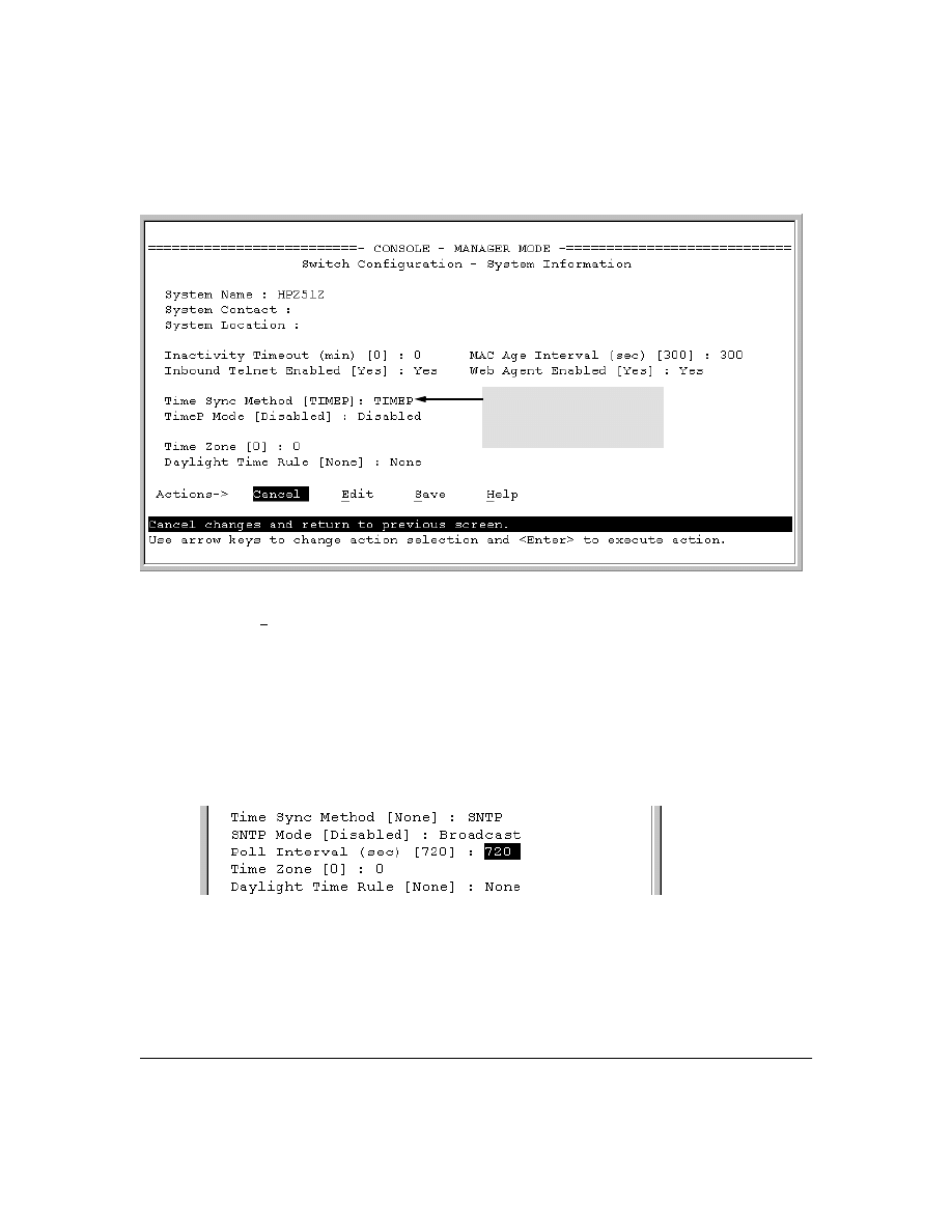
47
Figure 17. The System Information Screen (Default Values)
2.
Press
[E] (for
Edit
). The cursor moves to the
System Name
field.
3.
Use
[v] to move the cursor to the
Time Sync Method
field.
4.
Use the Space bar to select
SNTP
, then press
[v] once to display and move to the
SNTP Mode
field.
5.
Do one of the following:
•
Use the Space bar to select the
Broadcast
mode, then press
[v] to move the cursor to the
Poll Interval
field, and go to step 6. (For Broadcast mode details, see "SNTP Operating
Modes" on page 44.)
•
Use the Space bar to select the
Unicast
mode, then do the following:
i.
Press
[>] to move the cursor to the
Server Address
field.
ii.
Enter the IP address of the SNTP server you want the switch to use for time synchro-
nization.
Time Protocol Selection Parameter
– TIMEP
– SNTP
– None
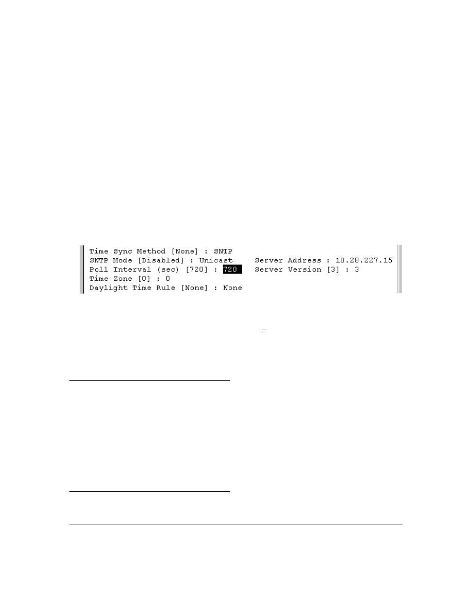
48
Note:
This step replaces any previously configured server IP address. If you
will be using backup SNTP servers (requires use of the CLI), then see
“SNTP Unicast Time Polling with Multiple SNTP Servers” on page 60.
iii. Press
[v] to move the cursor to the
Server Version
field. Enter the value that matches the
SNTP server version running on the device you specified in the preceding step (step ii).
If you are unsure which version to use, HP recommends leaving this value at the default
setting of
3
and testing SNTP operation to determine whether any change is necessary.
Note:
Using the menu to enter the IP address for an SNTP server when the switch already
has one or more SNTP servers configured causes the switch to delete the primary SNTP
server from the server list and to select a new primary SNTP server from the IP
address(es) in the updated list. For more on this topic, see “SNTP Unicast Time Polling
with Multiple SNTP Servers” on page 60.
iv. Press
[>] to move the cursor to the
Poll Interval
field, then go to step 6.
6.
In the
Poll Interval
field, enter the time in seconds that you want for a Poll Interval. (For Poll
Interval operation, see table 5, “SNTP Parameters”, on page 46.)
7.
Press
[Enter] to return to the Actions line, then [S] (for
Save
) to enter the new time protocol
configuration in both the startup-config and running-config files.
CLI: Viewing and Configuring SNTP
CLI Commands Described in this Section
This section describes how to use the CLI to view, enable, and configure SNTP parameters.
show sntp
page 49
[no] timesync
sntp broadcast
page 50
sntp unicast
page 50
sntp server
pages 50 and ff.
Protocol Version
page 52
poll-interval
page 52
no sntp
page 53
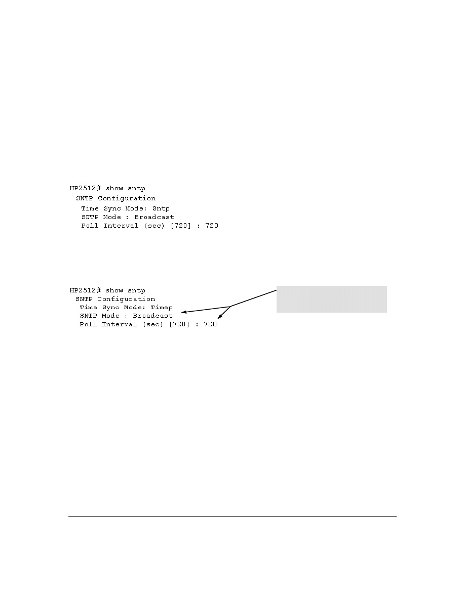
49
Viewing the Current SNTP Configuration
This command lists both the time synchronization method (TimeP, SNTP, or None) and the SNTP
configuration, even if SNTP is not the selected time protocol.
Syntax:
show sntp
For example, if you configured the switch with SNTP as the time synchronization method, then
enabled SNTP in broadcast mode with the default poll interval,
show sntp
lists the following:
Figure 18. Example of SNTP Configuration When SNTP Is the Selected Time Synchronization Method
In the factory-default configuration (where TimeP is the selected time synchronization method ),
show sntp
still lists the SNTP configuration even though it is not currently in use. For example:
Figure 19. Example of SNTP Configuration When SNTP Is Not the Selected Time Synchronization Method
Configuring (Enabling or Disabling) the SNTP Mode
Enabling the SNTP mode means to configure it for either broadcast or unicast mode. Remember that
to run SNTP as the switch’s time synchronization protocol, you must also select SNTP as the time
synchronization method by using the CLI
timesync
command (or the Menu interface
Time Sync Method
parameter).
Syntax:
timesync sntp
Selects SNTP as the time protocol.
sntp < broadcast | unicast >
Enables the SNTP mode (below and page 50).
sntp server < ip-addr>
Required only for unicast mode (page 50).
sntp poll-interval < 30 . . 720>
Enabling the SNTP mode also enables the SNTP poll
interval (default: 720 seconds; page 52).
Even though, in this example, TimeP is the
current time synchronous method, the
switch maintains the SNTP configuration.
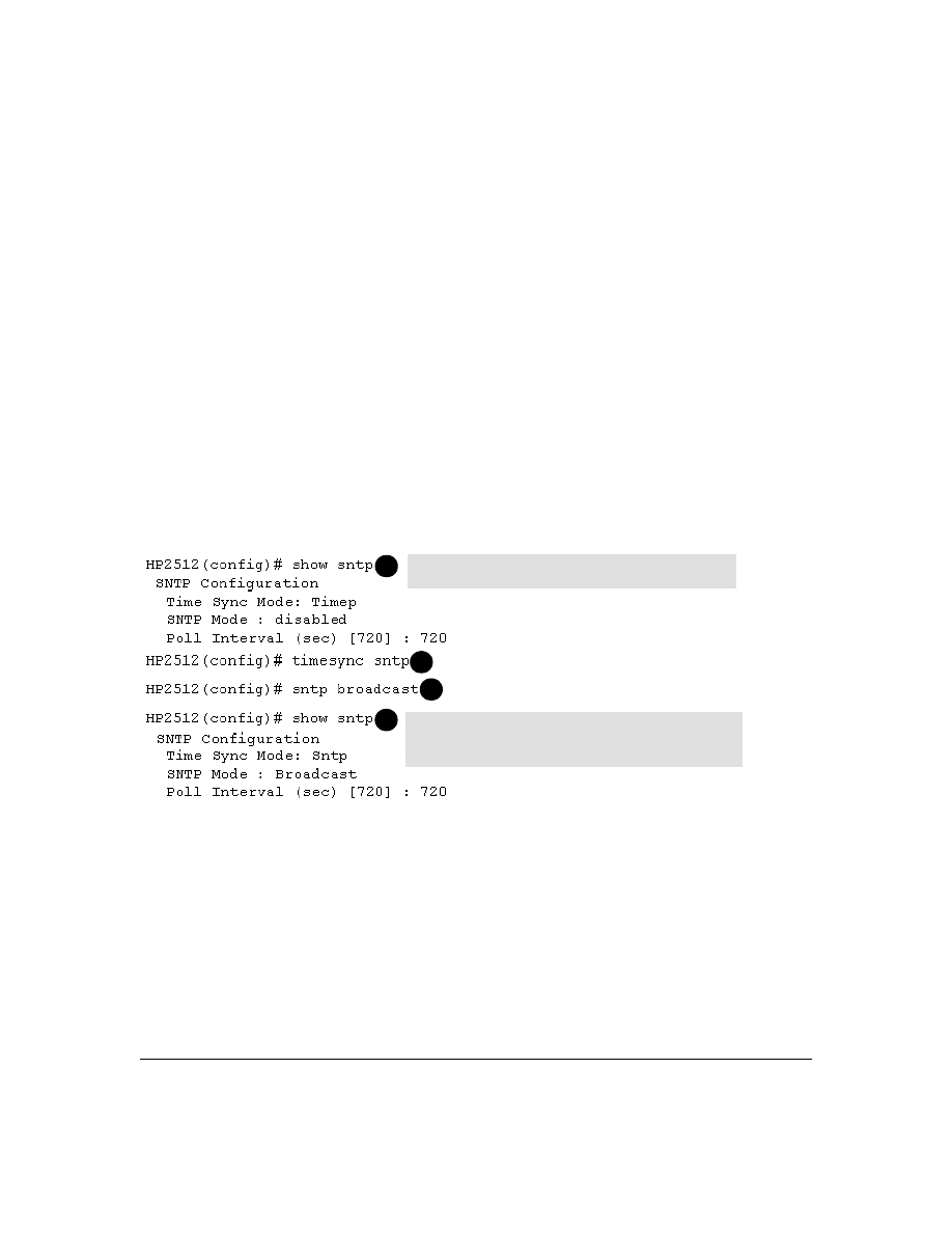
50
Enabling SNTP in Broadcast Mode.
Because the switch provides an SNTP polling interval
(default: 720 seconds), you need only these two commands for minimal SNTP broadcast configura-
tion:
Syntax:
timesync sntp
Selects SNTP as the time synchronization method.
sntp broadcast
Configures
Broadcast
as the SNTP mode.
For example, suppose:
■
Time synchronization is in the factory-default configuration (TimeP is the currently selected
time synchronization method).
■
You want to:
1. View the current time synchronization.
2. Select SNTP as the time synchronization mode.
3. Enable SNTP for Broadcast mode.
4. View the SNTP configuration again to verify the configuration.
The commands and output would appear as follows:
Figure 20. Example of Enabling SNTP Operation in Broadcast Mode
Enabling SNTP in Unicast Mode.
Like broadcast mode, configuring SNTP for unicast mode
enables SNTP. However, for Unicast operation, you must also specify the IP address of at least one
SNTP server. The switch allows up to three unicast servers. You can use the Menu interface or the
CLI to configure one server or to replace an existing Unicast server with another. To add a second
or third server, you must use the CLI. For more on SNTP operation with multiple servers, see “SNTP
Unicast Time Polling with Multiple SNTP Servers” on page 60.
show sntp displays the SNTP configuration and also shows
that TimeP is the currently active time synchronization mode.
1
2
3
show sntp again displays the SNTP configuration and shows that
SNTP is now the currently active time synchronization mode and is
configured for broadcast operation.
4
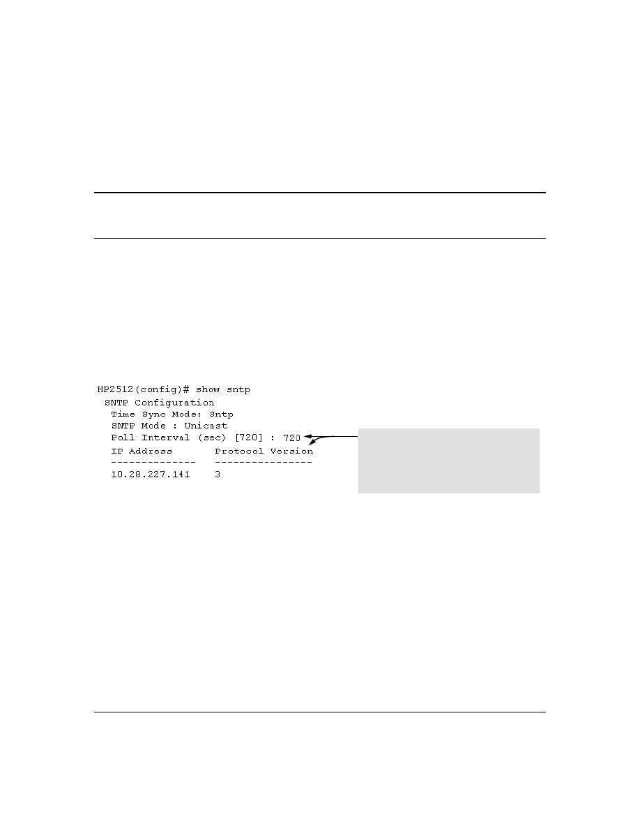
51
Syntax:
timesync sntp
Selects SNTP as the time synchronization method.
sntp unicast
Configures the SNTP mode for Unicast operation.
sntp server <ip-addr> [version]
Specifies the SNTP server. The default server version is
3.
no sntp server <ip-addr>
Deletes the specified SNTP server.
N o t e
Deleting an SNTP server when only one is configured disables SNTP unicast operation.
For example, to select SNTP and configure it with unicast mode and an SNTP server at 10.28.227.141
with the default server version (3) and default poll interval (720 seconds):
HP2512(config)# timesync sntp
Selects SNTP.
HP2512(config)# sntp unicast
Activates SNTP in Unicast mode.
HP2512(config)# sntp server 10.28.227.141
Specifies the SNTP server and accepts
the current SNTP server version
(default: 3)
.
Figure 21. Example of Configuring SNTP for Unicast Operation
If the SNTP server you specify uses SNTP version 4 or later, use the
sntp server command to specify
the correct version number. For example, suppose you learned that SNTP version 4 was in use on
the server you specified above (IP address 10.28.227.141). You would use the following commands
to delete the server IP address and then re-enter it with the correct version number for that server:
In this example, the Poll Interval and the Protocol
Version appear at their default settings.
Note: Protocol Version appears only when there is an
IP address configured for an SNTP server.
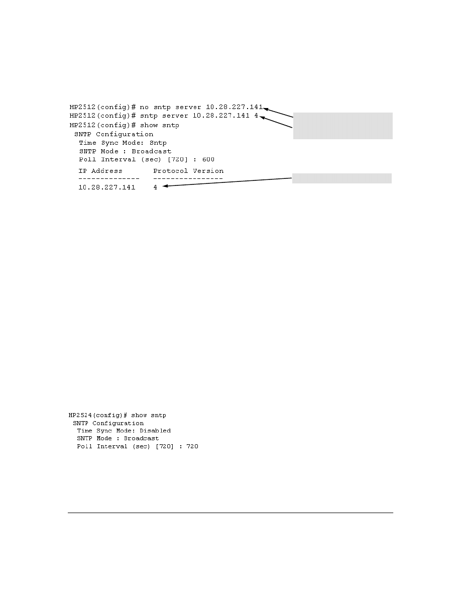
52
Figure 22. Example of Specifying the SNTP Protocol Version Number
Changing the SNTP Poll Interval.
This command lets you specify how long the switch waits
between time polling intervals. The default is 720 seconds and the range is 30 to 720 seconds. (This
parameter is separate from the poll interval parameter used for Timep operation.)
Syntax:
sntp poll-interval <30 . . 720>
For example, to change the poll interval to 300 seconds:
HP2512(config)# sntp poll-interval 300
Disabling Time Synchronization Without Changing the SNTP Configuration.
The recom-
mended method for disabling time synchronization is to use the
timesync
command. This halts time
synchronization without changing your SNTP configuration.
Syntax:
no timesync
For example, suppose SNTP is running as the switch’s time synchronization protocol, with
Broadcast
as the SNTP mode and the factory-default polling interval. You would halt time synchronization with
this command:
HP2512(config)# no timesync
If you then viewed the SNTP configuration, you would see the following:
Figure 23. Example of SNTP with Time Sychronization Disabled
Deletes unicast SNTP server entry.
Re-enters the unicast server with a non-
default protocol version.
show sntp displays the result.
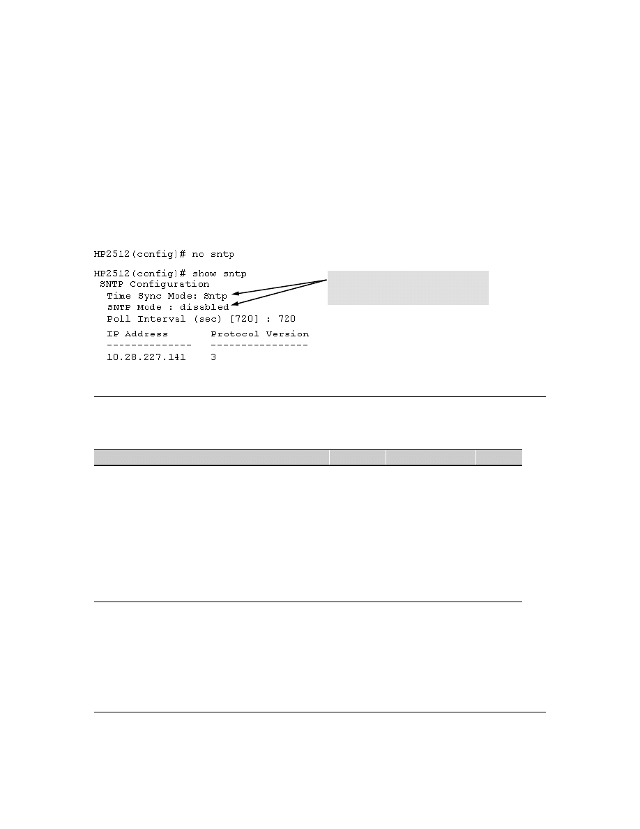
53
Disabling the SNTP Mode.
If you want to prevent SNTP from being used even if selected by
timesync
(or the Menu interface’s
Time Sync Method
parameter), configure the SNTP mode as disabled.
Syntax:
no sntp
Disables SNTP by changing the SNTP mode configuration to
Disabled
.
For example, if the switch is running SNTP in Unicast mode with an SNTP server at 10.28.227.141
and a server version of 3 (the default),
no sntp
changes the SNTP configuration as shown below, and
disables time synchronization on the switch.
Figure 24. Example of Disabling Time Synchronization by Disabling the SNTP Mode
TimeP: Viewing, Selecting, and Configuring
Timep Features
Feature
Default
Menu
CLI
Web
view the Timep time synchronization configuration
n/a
page 54
page 56
—
select Timep as the time syncronization method
TIMEP
page 53
pages 57
ff.
—
disable time synchronization
timep
page 55
page 59
—
enable the Timep mode
Disabled
—
DHCP
—
page 55
page 57
—
manual
—
page 55
page 58
—
none/disabled
—
page 55
page 60
—
change the SNTP poll interval
720 minutes
page 56
page 59
—
Even though the Time Sync Mode is set to Sntp,
time synchronization is disabled because no
sntp has disabled the SNTP Mode parameter.

54
Table 6. Timep Parameters
Menu: Viewing and Configuring TimeP
To View, Enable, and Modify the TimeP Protocol:
1.
From the Main Menu, select:
2. Switch Configuration...
1. System Information
SNTP Parameter Operation
Time Sync
Method
Used to select either TIMEP (the default), SNTP, or None as the time synchronization method.
Timep Mode
Disabled
The Default. Timep does not operate, even if specified by the Menu interface Time Sync Method
parameter or the CLI timesync command.
DHCP
When Timep is selected as the time synchronization method, the switch attempts to acquire a Timep
server IP address via DHCP. If the switch receives a server address, it polls the server for updates
according to the Timep poll interval. If the switch does not receive a Timep server IP address, it cannot
perform time synchronization updates.
Manual
When Timep is selected as the time synchronization method, the switch attempts to poll the specified
server for updates according to the Timep poll interval. If the switch fails to receive updates from the
server, time synchronization updates do not occur.
Server
Address
Used only when the TimeP Mode is set to Manual. Specifies the IP address of the TimeP server that
the switch accesses for time synchronization updates. You can configure one server.
Poll Interval
(minutes)
Default: 720 minutes. Specifies the interval the switch waits between attempts to poll the TimeP server
for updates.
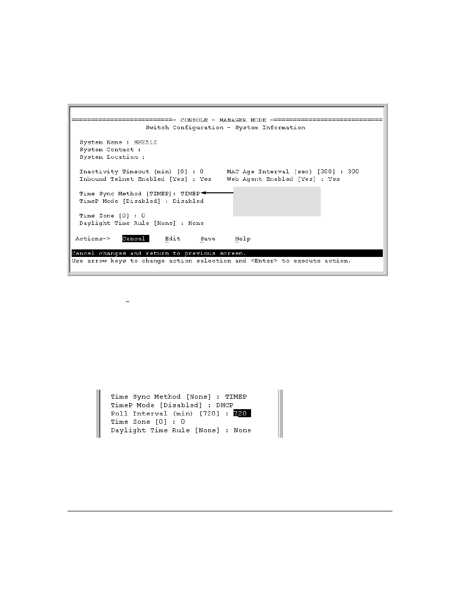
55
Figure 25. The System Information Screen (Default Values)
2.
Press
[E] (for
Edit
). The cursor moves to the
System Name
field.
3.
Use
[v] to move the cursor to the
Time Sync Method
field.
4.
If
TIMEP
is not already selected, use the Space bar to select
TIMEP
, then press
[v] once to display
and move to the
TimeP Mode
field.
5.
Do one of the following:
•
Use the Space bar to select the
DHCP
mode, then press
[v] to move the cursor to the
Poll
Interval
field, and go to step 6.
•
Use the Space bar to select the
Manual
mode.
i.
Press
[>] to move the cursor to the
Server Address
field.
ii.
Enter the IP address of the TimeP server you want the switch to use for time synchro-
nization.
Note:
This step replaces any previously configured TimeP server IP address.
Time Protocol Selection Parameter
– TIMEP (the default)
– SNTP
– None
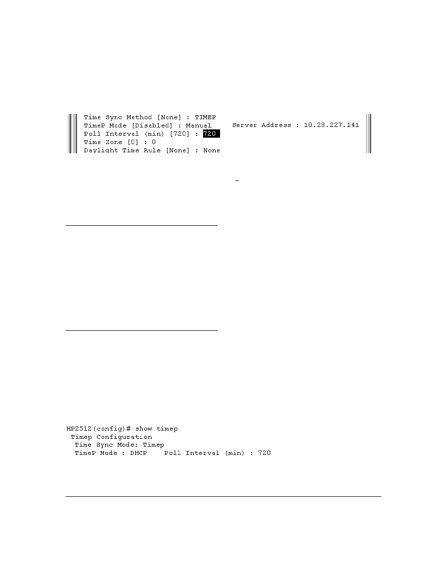
56
iii. Press
[>] to move the cursor to the
Poll Interval
field, then go to step 6.
6.
In the
Poll Interval
field, enter the time in minutes that you want for a TimeP Poll Interval.
Press
[Enter] to return to the Actions line, then [S] (for
Save
) to enter the new time protocol
configuration in both the startup-config and running-config files.
CLI: Viewing and Configuring TimeP
CLI Commands Described in this Section
This section describes how to use the CLI to view, enable, and configure TimeP parameters.
Viewing the Current TimeP Configuration
This command lists both the time synchronization method (TimeP, SNTP, or None) and the TimeP
configuration, even if SNTP is not the selected time protocol.
Syntax:
show timep
For example, if you configure the switch with TimeP as the time synchronization method, then enable
TimeP in DHCP mode with the default poll interval,
show timep
lists the following:
Figure 26. Example of TimeP Configuration When TimeP Is the Selected Time Synchronization Method
show timep
page 56
[no] timesync
ip timep
dhcp
page 57
manual
page 58
server <ip-addr>
page 58
interval
page 59
no ip timep
page 60
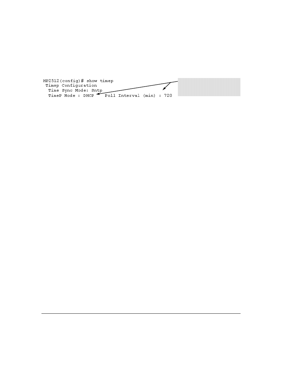
57
If SNTP is the selected time synchronization method ),
show timep
still lists the TimeP configuration
even though it is not currently in use:
Figure 27. Example of SNTP Configuration When SNTP Is Not the Selected Time Synchronization Method
Configuring (Enabling or Disabling) the TimeP Mode
Enabling the TimeP mode means to configure it for either broadcast or unicast mode. Remember
that to run TimeP as the switch’s time synchronization protocol, you must also select TimeP as the
time synchronization method by using the CLI timesync command (or the Menu interface
Time Sync
Method
parameter).
Syntax:
timesync timep
Selects TimeP as the time protocol.
ip timep < dhcp | manual >
Enables the selected TimeP mode.
no ip timep
Disables the TimeP mode.
no timesync
Disables the time protocol.
Enabling TimeP in DHCP Mode.
Because the switch provides a TimeP polling interval (default:
720 minutes), you need only these two commands for a minimal TimeP DHCP configuration:
Syntax:
timesync timep
Selects TimeP as the time synchronization method.
ip timep dhcp
Configures DHCP as the TimeP mode.
Even though, in this example, SNTP is the
current time synchronization method, the
switch maintains the TimeP
configuration.
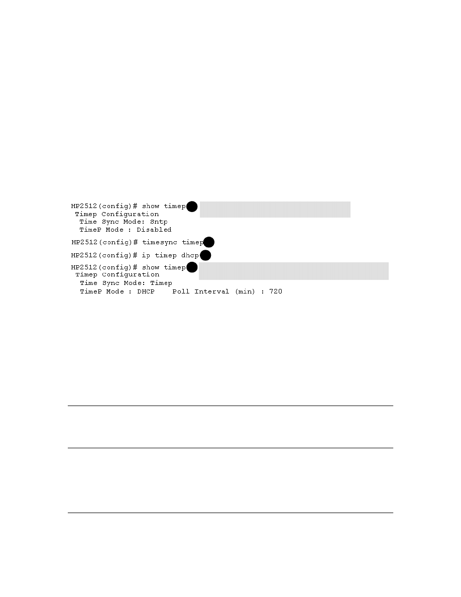
58
For example, suppose:
■
Time synchronization is configured for SNTP.
■
You want to:
1.View the current time synchronization.
2.Select TimeP as the time synchronization mode.
3.Enable TimeP for DHCP mode.
4.View the TimeP configuration.
The commands and output would appear as follows:
Figure 28. Example of Enabling TimeP Operation in DHCP Mode
Enabling Timep in Manual Mode.
Like DHCP mode, configuring TimeP for
Manual
mode enables
TimeP. However, for manual operation, you must also specify the IP address of the TimeP server.
(The switch allows only one TimeP server.) To enable the TimeP protocol:
Syntax:
timesync timep
Selects Timep.
ip timep manual <ip-addr>
Activates TimeP in Manual mode with a specified TimeP
server.
no ip timep
Disables TimeP
.
N o t e
To change from one TimeP server to another, you must (1) use the no ip timep command to disable
TimeP mode, and then reconfigure TimeP in Manual mode with the new server IP address.
For example, to select TimeP and configure it for manual operation using a TimeP server address of
10.28.227.141 and the default poll interval (720 minutes, assuming the TimeP poll interval is already
set to the default):
show timep displays the TimeP configuration and also shows
that SNTP is the currently active time synchronization mode.
1
2
3
4
show timep again displays the TimeP configuration and shows that TimeP is
now the currently active time synchronization mode.
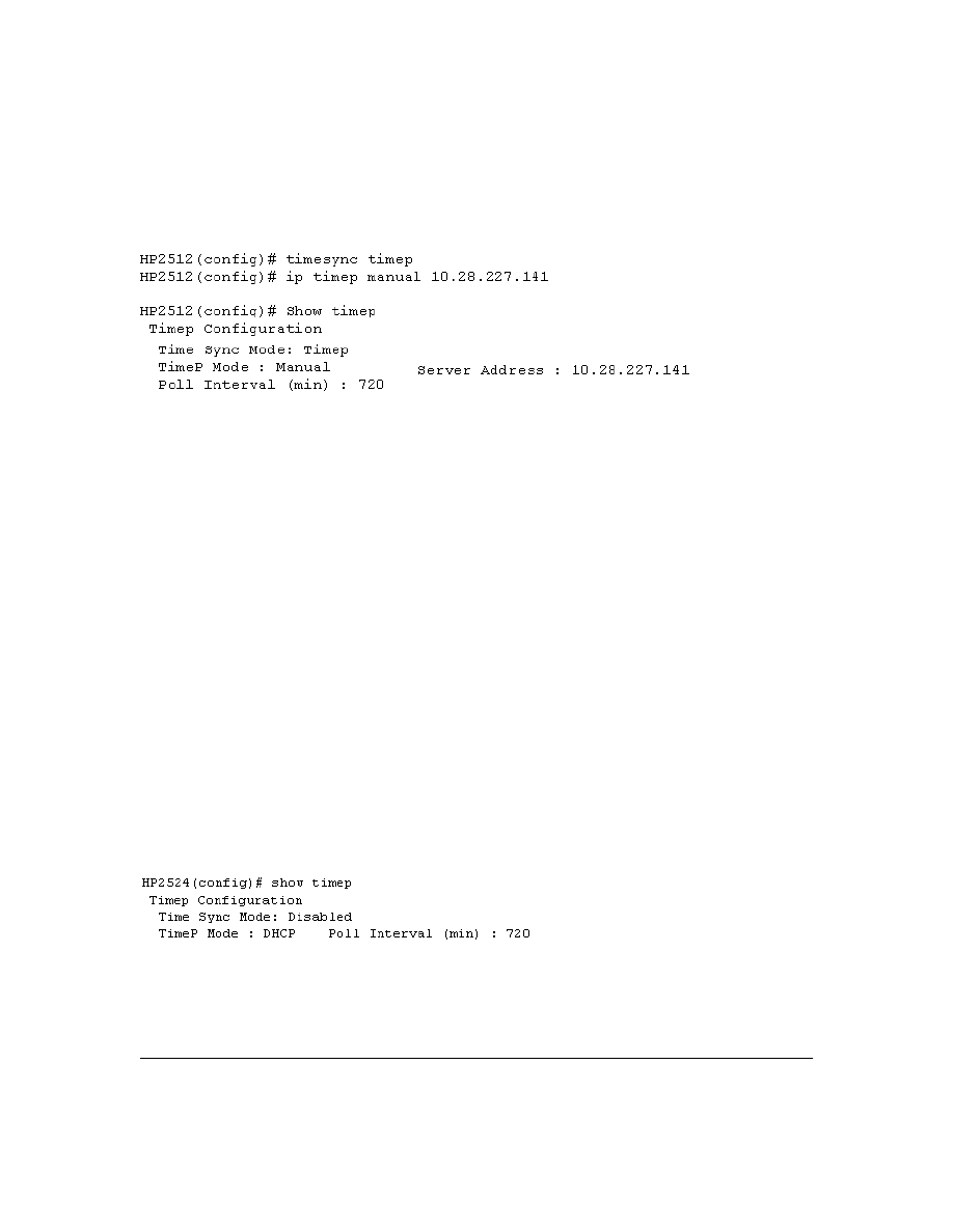
59
HP2512(config)# timesync timep
Selects TimeP.
HP2512(config)# ip timep manual 10.28.227.141
Activates TimeP in Manual mode.
Figure 29. Example of Configuring Timep for Manual Operation
Changing the TimeP Poll Interval.
This command lets you specify how long the switch waits
between time polling intervals. The default is 720 minutes and the range is 1 to 9999 minutes. (This
parameter is separate from the poll interval parameter used for SNTP operation.)
Syntax:
ip timep dhcp interval <1 . . 9999>
ip timep manual interval <1 . . 9999>
For example, to change the poll interval to 60 minutes:
HP2512(config)# ip timep interval 60
Disabling Time Synchronization Without Changing the TimeP Configuration.
The recom-
mended method for disabling time synchronization is to use the
timesync
command. This halts time
synchronization without changing your TimeP configuration.
Syntax:
no timesync
For example, suppose TimeP is running as the switch’s time synchronization protocol, with
DHCP
as
the TimeP mode, and the factory-default polling interval. You would halt time synchronization with
this command:
HP2512(config)# no timesync
If you then viewed the TimeP configuration, you would see the following:
Figure 30. Example of TimeP with Time Sychronization Disabled
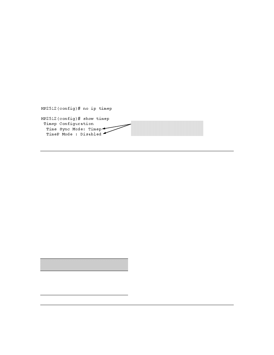
60
Disabling the TimeP Mode.
Disabling the TimeP mode means to configure it as disabled.
(Disabling TimeP prevents the switch from using it as the time synchronization protocol, even if it is
the selected
Time Sync Method
option.)
Syntax:
no ip timep
Disables TimeP by changing the TimeP mode configuration to
Disabled
.
For example, if the switch is running TimeP in DHCP mode,
no ip timep
changes the TimeP configura-
tion as shown below, and disables time synchronization on the switch.
Figure 31. Example of Disabling Time Synchronization by Disabling the TimedP Mode Parameter
SNTP Unicast Time Polling with Multiple SNTP Servers
When running SNTP unicast time polling as the time synchronization method, the switch requests a
time update from the server you configured with either the Server Address parameter in the menu
interface, or the primary server in a list of up to three SNTP servers configured using the CLI. If the
switch does not receive a response from the primary server after three consecutive polling intervals,
the switch tries the next server (if any) in the list. If the switch tries all servers in the list without
success, it sends an error message to the Event Log and reschedules to try the address list again after
the configured
Poll Interval
time has expired.
Address Prioritization
If you use the CLI to configure multiple SNTP servers, the switch prioritizes them according to the
decimal values of their IP addresses. That is, the switch compares the decimal value of the octets in
the addresses and orders them accordingly, with the lowest decimal value assigned as the primary
address, the second-lowest decimal value assigned as the next address, and the third-lowest decimal
value as the last address. If the first octet is the same between two of the addresses, the second octet
is compared, and so on. For example:
SNTP Server
IP Address
Server Ranking According to
Decimal Value of IP Address
10.28.227.141
Primary
10.28.227.153
Secondary
10.29.227.100
Tertiary
Even though the Time Sync Mode is set to Timep,
time synchronization is disabled because no ip
timep has disabled the TimeP Mode parameter.
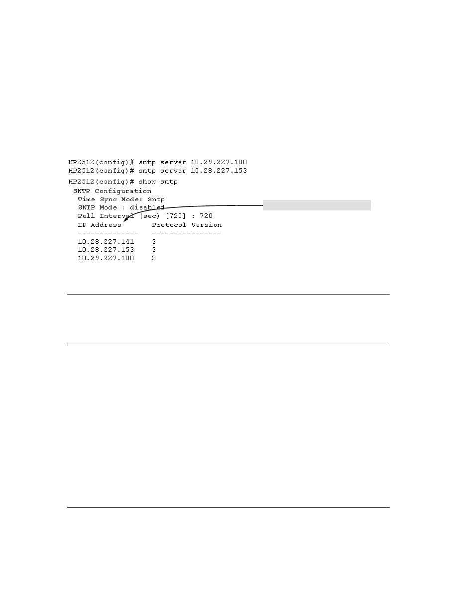
61
Adding and Deleting SNTP Server Addresses
Adding Addresses.
As mentioned earlier, you can configure one SNTP server address using either
the Menu interface or the CLI. To configure a second and third address, you must use the CLI. For
example, suppose you have already configured the primary address in the above table (10.28.227.141).
To configure the remaining two addresses, you would do the following:
Figure 32. Example of SNTP Server Address Prioritization
N o t e
If there are already three SNTP server addresses configured on the switch, and you want to use the
CLI to replace one of the existing addresses with a new one, you must delete the unwanted address
before you configure the new one.
Deleting Addresses.
To delete an address, you must use the CLI. If there are multiple addresses
and you delete one of them, the switch re-orders the address priority. (See “Address Prioritization”
on page 60.)
Syntax:
no sntp server <ip-addr>
For example, to delete the primary address in the above example (and automatically convert the
secondary address to primary):
HP2512(config)# no sntp server 10.28.227.141
Prioritized list of SNTP Server IP Addresses

62
Menu Interface Operation with Multiple SNTP Server Addresses Configured
When you use the Menu interface to configure an SNTP server IP address, the new address writes
over the current primary address, if one is configured. If there are multiple addresses configured, the
switch re-orders the addresses according to the criteria described under “Address Prioritization” on
page 60. For example, suppose the switch already has the following three SNTP server IP addresses
configured.
■
10.28.227.141 (primary)
■
10.28.227.153 (secondary)
■
10.29.227.100 (tertiary)
If you use the Menu interface to add 10.28.227.160, the new prioritized list will be:
SNTP Messages in the Event Log
If an SNTP time change of more than three seconds occurs, the switch’s event log records the change.
SNTP time changes of less than three seconds do not appear in the Event Log.
New Address List
Address Status
10.28.227.153
New Primary (The former primary, 10.28.227.141 was deleted when you used the menu to add
10.28.227.160.)
10.28.227.160
New Secondary
10.29.227.100
Same Tertiary (This address still has the highest decimal value.)

63
Operation and Enhancements for Multimedia
Traffic Control (IGMP)
How Data-Driven IGMP Operates
The information in this section supplements the information provided under "Multimedia Traffic
Control with IP Multicast (IGMP)" beginning on page 9-91 in the Management and Configuration
Guide included with your Series 2500 switch and also available at
http://www.hp.com/go/hpprocurve
.
This section uses the following terms to describe IGMP operation:
■
Querier:
A required IGMP device that facilitates the IGMP protocol and traffic flow on a
given LAN. This device tracks which ports are connected to devices (IGMP clients) that
belong to specific multicast groups, and triggers updates of this information. With IGMP
enabled, the Series 2500 switches use data from the Querier to determine whether to forward
or block multicast traffic on specific ports. When the switch has an IP address on a given
VLAN, it automatically operates as a Querier for that VLAN if it does not detect a multicast
router or another switch functioning as a Querier.
■
IGMP Device:
A switch or router running IGMP traffic control features.
■
IGMP Host:
An end-node device running an IGMP (multipoint, or multicast communication)
application.
Without IGMP enabled, the switch simply floods all IP multicast traffic it receives on a given VLAN
through all ports on that VLAN (except the port on which it received the traffic). This can result in
significant and unnecessary bandwidth usage in networks where IP multicast traffic is a factor. Data-
Driven IGMP reduces this problem by authorizing the switch to restrict multicast traffic only to ports
where a given multicast group should flow.
Series 2500 switches (all software versions) use data-driven IGMP to better control IP multicast
traffic.
An IP multicast packet includes the multicast group (address) to which the packet belongs. When an
IGMP client connected to a switch port needs to receive multicast traffic from a specific group, it
joins the group by sending an IGMP report (join request) to the network. (The multicast group
specified in the join request is determined by the requesting application running on the IGMP client.)
When a networking device with IGMP enabled receives the join request for a specific group, it
forwards any IP multicast traffic it receives for that group through the port on which the join request
was received. To reduce unnecessary traffic, the networking device does not forward a given group’s
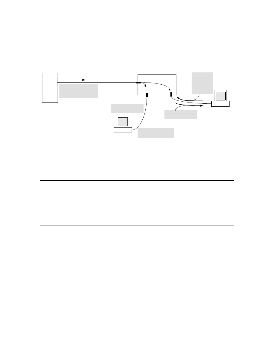
64
multicast packets to ports from which a join request for that group has not been received. (If the
switch or router has not received any join requests for a given multicast group, it drops the traffic it
receives for that group.)
Figure 33. Example of Data-Driven IGMP Operation
Thus, after you enable IGMP on a VLAN configured in the switch, it continually listens for IGMP
messages and IP multicast traffic on all ports in the VLAN, and forwards IGMP traffic for a given
multicast address only through the port(s) on that VLAN where an IGMP report (join request) for
that address was received from an IGMP client device.
N o t e
IP multicast traffic groups are identified by IP addresses in the range of 224.0.0.0 to 239.255.255.255.
Incoming IGMP packets intended for reserved, or "well-known" multicast addresses automatically
flood through all ports (except the port on which the packets entered the switch). For more on this
topic, see “The Switch Excludes Well-Known or Reserved Multicast Addresses from IP Multicast
Filtering” on page 70.
New: IGMP Now Operates With or Without IP Addressing
Formerly, IGMP operation on the Series 2500 switches required an IP address and subnet mask for
each VLAN running IGMP. Beginning with release F.02.xx, you can configure IGMP on VLANs that
do not have IP addressing. The benefit of IGMP without IP addressing is a reduction in the number
of IP addresses you have to use and configure. This can be significant in a network with a large
number of VLANs. The limitation on IGMP without IP addressing is that the switch cannot become
Querier on any VLANs for which it has no IP address—so the network administrator must ensure
that another IGMP device will act as Querier and that an additional IGMP device is available as a
backup Querier.
Video
Server
Series 2500 Switch
Host "A1"
Outbound Multicast
Traffic from Video Server
for Group "A" on VLAN 3
Drop
Join Request
for group "A"
from Host A1
on VLAN 3
Host "A2"
Group "A" Multicast
Traffic for Host "A1"
No Join Request from
Host A2 on VLAN 3
No Group "A" Multicast
Traffic for Host "A2"
Forward

65
Fast-Leave IGMP
IGMP Operation Presents a "Delayed Leave" Problem.
Where multiple IGMP clients are
connected to the same port on an IGMP device (switch or router), if only one IGMP client joins a
given multicast group, then later sends a Leave Group message and ceases to belong to that group,
the IGMP device retains that IGMP client in its IGMP table and continues forwarding IGMP traffic to
the IGMP client until the Querier triggers confirmation that no other group members exist on the
same port. This means that the switch continues to transmit unnecessary multicast traffic through
the port until the Querier renews multicast group status.
Fast-Leave IGMP Reduces Leave Delays.
Fast-Leave IGMP operates on a port if an IGMP client
connects to the port and there are no other end nodes detected on that port. In this case, when the
client leaves a multicast group, Fast-Leave IGMP automatically accelerates the blocking of further,
unnecessary multicast traffic from that group to the former IGMP client. This improves performance
by reducing the amount of multicast traffic going through the port to the IGMP client after the client
leaves a multicast group. IGMP in the Series 2500 switches automatically uses this Fast-Leave feature.
IGMP Function Available With IP Addressing
Configured on the VLAN
Available
Without IP
Addressing?
Operating Differences Without an IP Address
Drop multicast group traffic for which there
have been no join requests from IGMP clients
connected to ports on the VLAN.
Yes
None
Forward multicast group traffic to any port on
the VLAN that has received a join request for
that multicast group.
Yes
None
Forward join requests (reports) to the Querier.
Yes
None
Configure individual ports in the VLAN to Auto
(the default)/Blocked, or Forward.
Yes
None
Configure IGMP traffic forwarding to normal or
high-priority forwarding.
Yes
None
Age-Out IGMP group addresses when the last
IGMP client on a port in the VLAN leaves the
group.
Yes
Requires that another IGMP device in the VLAN has an IP
address and can operate as Querier. This can be a multi-
cast router or another switch configured for IGMP oper-
ation. (HP recommends that the VLAN also include a
device operating as a backup Querier in case the device
operating as the primary Querier fails for any reason.
Support Fast-Leave IGMP (below) and Forced
Fast-Leave IGMP (page 67).
Yes
Support automatic Querier election.
No
Querier operation not available.
Operate as the Querier.
No
Querier operation not available.
Provide a backup Querier.
No
Querier operation not available.
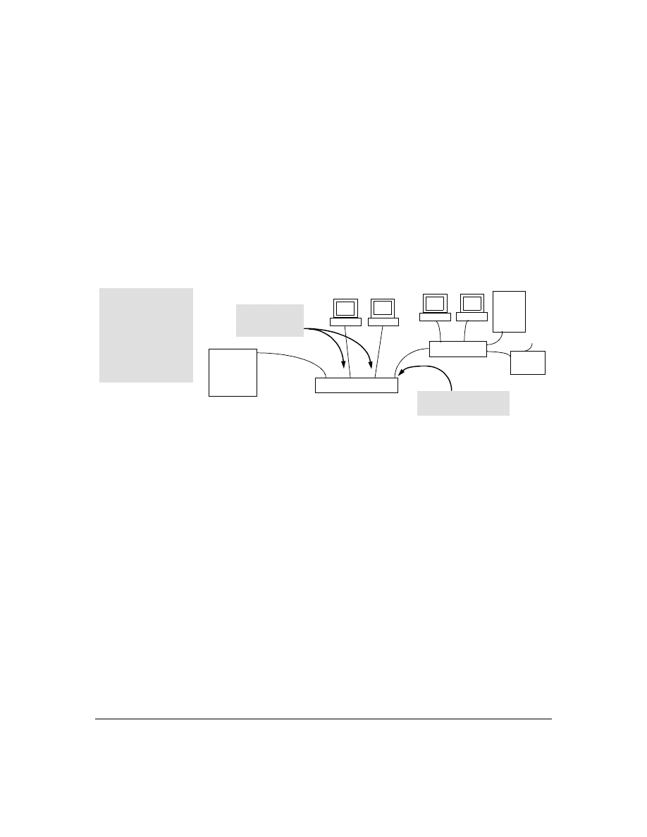
66
Automatic Fast-Leave Operation.
If a Series 2500 switch port is :
a.
Connected to only one end node
b.
The end node currently belongs to a multicast group; i.e. is an IGMP client
c.
The end node subsequently leaves the multicast group
Then the switch does not need to wait for the Querier status update interval, but instead immediately
removes the IGMP client from its IGMP table and ceases transmitting IGMP traffic to the client. (If
the switch detects multiple end nodes on the port, automatic Fast-Leave does not activate—
regardless of whether one or more of these end nodes are IGMP clients.)
In the next figure, automatic Fast-Leave operates on the switch ports for IGMP clients "3A" and "5B",
but not on the switch port for IGMP clients "7A" and 7B, Server "7C", and printer "7D".
Figure 34. Example of Automatic Fast-Leave IGMP Criteria
When client "3A" running IGMP is ready to leave the multicast group, it transmits a Leave Group
message. Because the Series 2500 switch knows that there is only one end node on port 3, it removes
the client from its IGMP table and halts multicast traffic (for that group) to port 3. If the switch is not
the Querier, it does not wait for the actual Querier to verify that there are no other group members
on port 3. If the switch itself is the Querier, it does not query port 3 for the presence of other group
members.
Note that Fast-Leave operation does not distinguish between end nodes on the same port that belong
to different VLANs. Thus, for example, even if all of the devices on port 7 in figure 34 belong to
different VLANs, Fast-Leave does not operate on port 7.
Routing
Switch
Acting as
Querier
Series 2500 Switch
Server
7C
Switch 7X
3A
5A
7A
Fast-Leave IGMP
automatically operates on
the ports connected to
IGMP clients 3A and 5A,
but does not operate on
the port connected to
Switch 7X because the
Series 2500 switch
detects multiple end
nodes on that port.
Fast-Leave IGMP does
not activate on this port.
Fast-Leave IGMP
activates on these
two ports.
1
3
5
7
Printer
7D
7B

67
New: Forced Fast-Leave IGMP
Forced Fast-Leave IGMP Features
Forced Fast-Leave IGMP speeds up the process of blocking unnecessary IGMP traffic to a switch
port that is connected to multiple end nodes. (This feature does not activate on ports where the switch
detects only one end node. Instead, the regular Fast Leave described in the preceding section
activates.) For example, in figure 34, even if you configured Forced Fast-Leave on all ports in the
switch, the feature would activate only on port 7 (which has multiple end nodes) when a Leave Group
request arrived on that port.
When a port having multiple end nodes receives a Leave Group request from one end node for a given
multicast group "X", Forced Fast-Leave activates and waits a small amount of time to receive a join
request from any other group "X" member on that port. If the port does not receive a join request for
that group within the forced-leave interval, the switch then blocks any further group "X" traffic to the
port.
Configuration Options for Forced Fast-Leave
CLI: Listing the Forced Fast-Leave Configuration
The Forced Fast-Leave configuration includes the state (enabled or disabled) for each port and the
Forced-Leave Interval for all ports on the switch.
To list the Forced Fast-Leave state for all ports in the switch:
Syntax:
HP2512# walkmib hpSwitchIgmpPortForcedLeaveState.1
or
HP2512# walkmib 1.3.6.1.4.1.11.2.14.11.5.1.7.1.15.3.1.5.1
Feature
Default
Menu
CLI
Web
view the Forced Fast-Leave configuration
view the switch’s Forced Fast-Leave state
n/a
—
page 67
—
configure Forced Fast-Leave
configure Forced Fast-Leave for an individual port
2 (disabled)
—
page 68
—
Feature
Default
Settings
Function
Forced Fast-
Leave state
2 (disabled) 1 (enabled)
2 (disabled)
Uses the setmib command to enable or disable Forced Fast-Leave on
individual ports. When enabled on a port, Forced Fast-Leave operates only if
the switch detects multiple end nodes (and at least one IGMP client) on that
port.
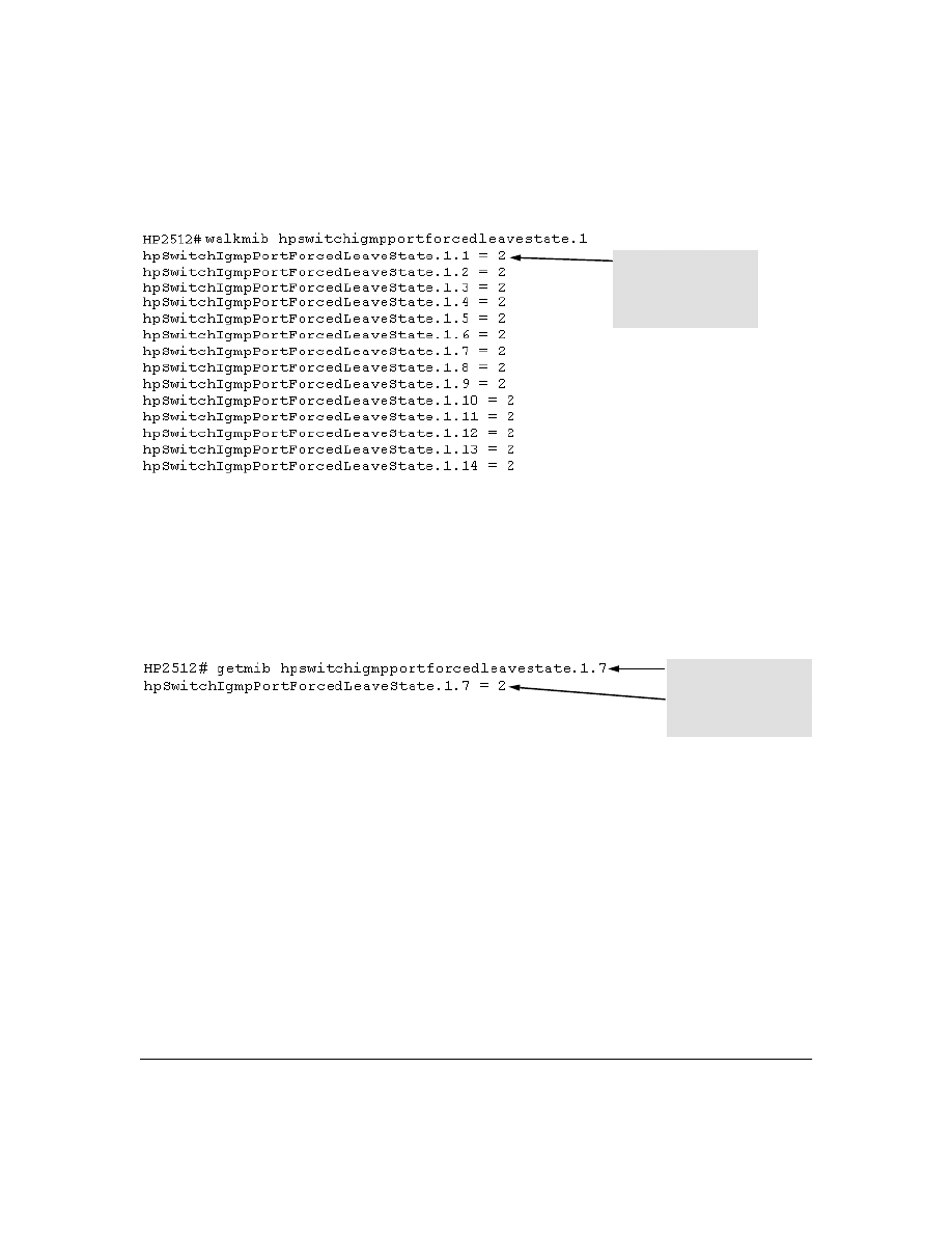
68
For example:
Figure 35. Listing the Forced Fast-Leave State for Ports in an HP2512 Switch
To list the Forced Fast-Leave state for a single port.
Syntax:
getmib hpSwitchIgmpPortForcedLeaveState.1. <port-number>
(Not case-sensitive.)
getmib 1.3.6.1.4.1.11.2.14.11.5.1.7.1.15.3.1.5.1. <port-number>
For example, to use either of the above command versions to list the state for port 7:
Figure 36. Listing the Forced Fast-Leave State for a Single Port
CLI: Configuring Per-Port Forced Fast-Leave IGMP
In the factory-default configuration, Forced Fast-Leave is disabled for all ports on the switch. To
enable (or disable) this feature on individual ports, use the switch’s MIB commands, as shown below.
Syntax:
setmib hpSwitchIgmpPortForcedLeaveState.1.<port-number> -i < 1 | 2 >
or
setmib 1.3.6.1.4.1.11.2.14.11.5.1.7.1.15.3.1.5.1.<port-number> -i < 1 | 2 >
where
:
1 = Forced Fast-Leave enabled
2 = Forced Fast-Leave disabled
In this example, the
2
at the
end of each port listing
shows that Fast Forced-
Leave is disabled on all
ports in the switch.
The
7 specifies port 7.
The 2 shows that Fast
Forced-Leave is disabled on
port 7.
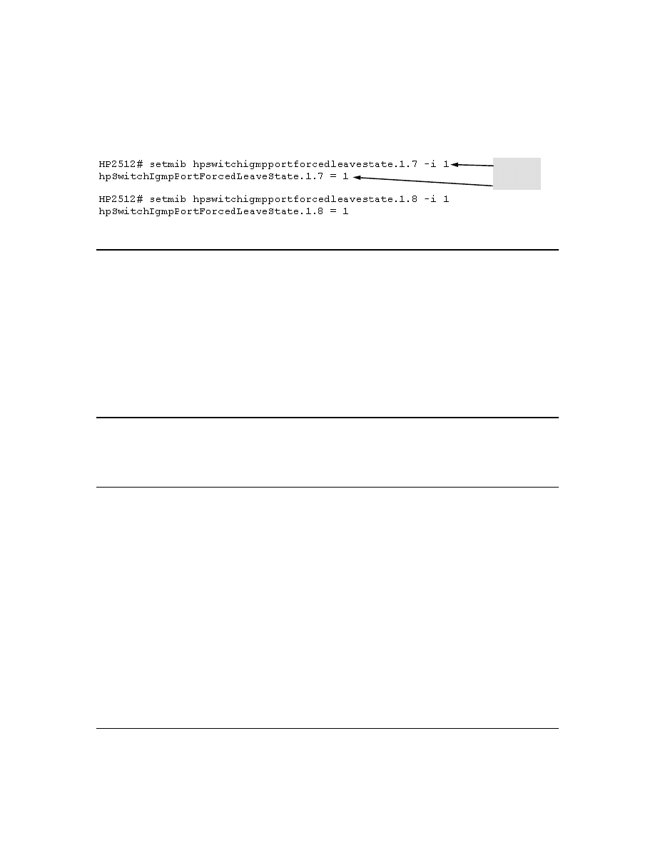
69
For example, to enable Forced Fast-Leave on ports 7 and 8:
Figure 37. Example of Changing the Forced Fast-Leave Configuration on Ports 7 and 8
Querier Operation
The function of the IGMP Querier is to poll other IGMP-enabled devices in an IGMP-enabled VLAN
to elicit group membership information. The switch performs this function if there is no other device
in the VLAN, such as a multicast router, to act as Querier. Although the switch automatically ceases
Querier operation in an IGMP-enabled VLAN if it detects another Querier on the VLAN, you can also
use a CLI command to disable the Querier function for that VLAN. For example, to disable the Querier
function on VLAN 1 in a Series 2500 switch:
HP2512(config)# no vlan 1 ip igmp querier
Disables Querier function on VLAN 1.
HP2512(vlan-1)# no ip igmp querier
Disables Querier function on VLAN 1
from within the VLAN 1 context.
N o t e
A Querier is required for proper IGMP operation. For this reason, if you disable the Querier function
on a Series 2500 switch, ensure that there is an IGMP Querier (and, preferably, a backup Querier)
available on the same VLAN.
If the switch becomes the Querier for a particular VLAN (for example, the DEFAULT_VLAN), then
subsequently detects queries transmitted from another device on the same VLAN, the switch ceases
to operate as the Querier for that VLAN. If this occurs, the switch Event Log lists a pair of messages
similar to these:
I 01/15/01 09:01:13 igmp: DEFAULT_VLAN: Other Querier detected
I 01/15/01 09:01:13 igmp: DEFAULT_VLAN: This switch is no longer Querier
In the above scenario, if the other device ceases to operate as a Querier on the default VLAN, then
the switch detects this change and can become the Querier as long as it is not pre-empted by some
other IGMP Querier on the VLAN. In this case, the switch Event Log lists messages similar to the
following to indicate that the switch has become the Querier on the VLAN:
I 01/15/01 09:21:55 igmp: DEFAULT_VLAN: Querier Election in process
I 01/15/01 09:22:00 igmp: DEFAULT_VLAN: This switch has been elected as
Querier
Command
Verification

70
The Switch Excludes Well-Known or Reserved Multicast Addresses
from IP Multicast Filtering
Each multicast host group is identified by a single IP address in the range of 224.0.0.0 through
239.255.255.255. Specific groups of consecutive addresses in this range are termed "well-known"
addresses and are reserved for predefined host groups. IGMP does not filter these addresses, so any
packets the switch receives for such addresses are flooded out all ports assigned to the VLAN on
which they were received (except the port on which the packets entered the VLAN). The following
table lists the 32 well-known address groups (8192 total addresses) that IGMP does not filter on the
Series 2500 switches.
Table 7. Well-Known IP Multicast Address Groups Excluded from IGMP Filtering
Switch Memory Operation
If you are using the CLI to change the switch configuration, HP recommends that you use the
write
memory
command to permanently save the changes (to the startup-config file) before exiting from the
CLI. CLI configuration changes are not saved from the Menu interface to the startup-config file unless
you make a configuration change in the Menu interface before using the
Save
command. That is, if
you use the CLI to make a change to the running-config file and then go to the Menu interface and
execute a
Save
command without making a configuration change in the Menu interface, the CLI
change made to the running-config file is not saved to the startup-config file. (You can still save the
change by returning to the global configuration level in the CLI and executing
write memory
). For more
on memory operation, see appendix C, "Switch Memory and Configuration" in the HP Procurve Series
2500 Switches Management and Configuration Guide
shipped with your switch and also available
at http://www.hp.com/go/hpprocurve. (Click on technical support, then manuals.) See also "Incom-
plete Information on Saving Configuration Changes" on page 78.
Groups of Consecutive
Addresses in the Range of
224.0.0.X to 239.0.0.X*
Groups of Consecutive
Addresses in the Range of
224.128.0.X to 239.128.0.X*
224.0.0.x
232.0.0.x
224.128.0.x
232.128.0.x
225.0.0.x
233.0.0.x
225.128.0.x
233.128.0.x
226.0.0.x
234.0.0.x
226.128.0.x
234.128.0.x
227.0.0.x
235.0.0.x
227.128.0.x
235.128.0.x
228.0.0.x
236.0.0.x
228.128.0.x
236.128.0.x
229.0.0.x
237.0.0.x
229.128.0.x
237.128.0.x
230.0.0.x
238.0.0.x
230.128.0.x
238.128.0.x
231.0.0.x
239.0.0.x
231.128.0.x
239.128.0.x
* X is any value from 0 to 255.

71
Port Security: Changes to Retaining Learned Static
Addresses Across a Reboot
Recommended Port Security Procedures
■
Before configuring port security, use the switch’s TFTP features to save a copy of the
configuration. In the event that you later want to remove the switch’s port security configu-
ration (including MAC addresses the switch has authorized) and reconfigure port security,
your task will be easier.
■
If you want to manually configure the authorized MAC addresses for a port (instead of
allowing the switch to learn whatever MAC addresses it detects first on the port), then prior
to configuring the Static learn mode on a port, remove the LAN link from the port. This
prevents the port from automatically learning MAC addresses that you do not want to include
in the authorized list. After you use the
port-security <port-list> mac-address <mac-addr>
command
to configure the authorized addresses you want in the list, reconnect the link.
■
After you configure the authorized MAC addresses you want on a port, execute the write
memory command to make these addresses permanent in the switch’s configuration. (See
the "Assigned/Authorized Address" bullet under "Retention of Static Addresses" in the next
subsection.)
Retention of Static Addresses
Beginning with release F.02.xx, port security operation has changed to the operation described below.
These changes affect information provided in Table 7-1, "Port Security Parameters" on pages 7-14 and
7-15 in the Management and Configuration Guide (p/n 5969-2354) provided for the Series 2500
switches.
■
Learned Addresses:
In the following two cases, a port in Static learn mode retains a learned
MAC address even if you subsequently reboot the switch or disable port security for that port:
•
The port learns a MAC address after you configure the port for Static learn mode in both
the startup-config file and the running-config files (by executing the
write memory
command).
•
The port learns a MAC address after you configure the port for Static learn mode in only
the running-config file and, after the address is learned, you execute
write memory
to
configure the startup-config file to match the running-config file.

72
To remove an address learned using either of the preceding methods, do one of the following:
•
Delete the address by using the
no port-security <port-number> mac-address <mac-addr>
command.
•
Download a previously saved configuration file that does not include the unwanted MAC
address assignment.
•
Reset the switch to its factory-default configuration.
■
Assigned/Authorized Address:
If you manually assign a MAC address (using the
port-
security <port-number> address-list <mac-addr>
command) and then you execute a
write memory
command, the assigned MAC address remains in memory until you do one of the following:
•
Delete it by using the
no port-security <port-number> mac-address <mac-addr>
command.
•
Download a previously saved configuration file that does not include the unwanted MAC
address assignment.
•
Reset the switch to its factory-default configuration.
Disabling port security on a port does not remove an assigned MAC address from the port security
configuration for that port.
Username Assignment and Prompt
Prior to release F.02.xx, assigning a manager or operator username to the switch required you to use
the web browser interface. Also, only the web browser interface required you to enter a username
at logon if one was configured for the privilege level you were accessing. Beginning with release
F.02.xx you can use the CLI
password
command to assign a manager- and/or operator-level username,
and the CLI and web browser interface will require you to enter a username at logon if one is
configured.
N o t e
On the series 2500 switches, a username is optional.
Syntax:
password <manager | operator> [user-name <user-name-str>]
For example, to use the CLI to configure a manager user name of
sysman1
and a manager password
of
top1mgr
:

73
HP2512(config# password manager user-name sysman1
New password: *******
Please retype new password: *******
To use the CLI to remove all user name and password protection from the switch:
HP2512(config)# no password
Series 2500 FAQs from the HP Procurve Website
Q1: Is 10/100Mbps auto-negotiation the same as Plug-n-Play?
A:
No. The following configuration will cause severe network problems:
The hub, switch, or router will correctly sense (not auto-negotiate) the 10Mbps or 100Mbps speed.
Since the end node was configured for a specific speed and duplex state and therefore does not
negotiate, the hub, switch, or router will choose the communication mode specified by the 802.3u
standard, namely half-duplex.
With one device running at half-duplex and the device on the other end of the connection at full-
duplex, the connection will work reasonably well at low levels of traffic. At high levels of traffic the
full-duplex device (end node, in this case) will experience an abnormally high level of CRC or
alignment errors. The end users usually describe this situation as, "Performance seems to be
approximately 1Mbps!" Often, end nodes will drop connections to their servers.
In this same situation, the half-duplex device will experience an abnormally high level of late
collisions.
The network administrator must take care to verify the configuration of each network device during
installation. Also, check the operational mode of each network device. That is, check both how you
configured it and also that it comes up as you expect, for example, at 10Mbps/half-duplex.
Q2: When I connected my new HP Procurve Series 2500 switch to my HP Procurve Switch
4000M using a Gigabit-SX or Gigabit-LX connection, the link did not come up. Why not?
A:
The HP Procurve Gigabit-SX module used in the HP Procurve Switch 4000M, 8000M, 1600M, 2424M
and 2400M is set by factory-default to "1000 Fdx" whereas the factory-default setting for the HP
Procurve Gigabit-SX transceiver used in the HP Procurve Series 2300 and 2500 switches is "Auto".
The configuration must be set to match on both ends to provide Gigabit connectivity.
10/100 Hub/Switch/Router/Etc. with
Port Configured for Auto-Negotiation
End-Node Configured for
100Mbps/Full-Duplex
or 10Mbps/Full-Duplex

74
Q3: By default, VLAN support on the HP Procurve Series 2500 switches is enabled. Can you
disable VLAN support like you can on the HP Procurve Switch 4000M?
A:
No. VLAN support cannot be disabled on the HP Procurve Series 2500 switches. By default, all
ports are configured in the default VLAN (DEFAULT_VLAN). The following table shows the differ-
ences between the HP Procurve Switch 4000M, 8000M, 1600M, 2424M and 2400M and the HP Procurve
Series 2500 switches with respect to VLAN support:
Q4: My HP Procurve Series 2500 switch is configured with multiple VLANs and I want to
use DHCP to learn its IP address and default gateway for each VLAN.
Since the HP Procurve
Series 2500 switches support a single global default gateway, which of the DHCP supplied default
gateway addresses will the switch use?
A:
The Series 2500 switches will use the DHCP information received for the VLAN configured as the
"Primary VLAN". In the factory-default configuration, the switch designates the default VLAN
(DEFAULT_VLAN) as the "Primary VLAN". However, you can designate another VLAN as the "Primary
VLAN" using the "Primary VLAN" configuration option. For more information, refer to chapter 9 of
the HP Procurve Series 2500 Switches Management and Configuration Guide.
Q5: When I start a console session on my new HP Procurve Series 2500 switch, I get the
prompt "HP Procurve Switch 2524#." How do I access the menu interface?
A:
The default interface for the HP Procurve Series 2500 switches is the Command Line Interface
(CLI). The CLI is a full-featured interface that can be used to get status information (show commands)
and perform configuration changes (configuration context). To access the menu interface, issue the
command "menu" from the CLI. Also, using the "setup" command from the CLI or menu interface
allows you to configure most of the basic options on the switch such as IP addressing and passwords.
Q6: When STP is configured off, do the Switch 2512 and Switch 2524 forward STP BPDUs
that they receive?
A:
Yes. Note that the Switches 1600M, 2400M, 2424M, 4000M, and 8000M do not forward STP BPDUs
when STP is configured off in those switches.
Q7: How can I set the time or date?
A:
Use the global configuration mode time command in the Command Line Interface.
Feature
Switches 4000M, 8000M,
1600M, 2424M, and 2400M
Switch 2512 and 2524
VLAN Support
Options
Disable (default)
Enable
Always enabled
(cannot disable)
Default VLAN
Can change VID.
Cannot change VID.
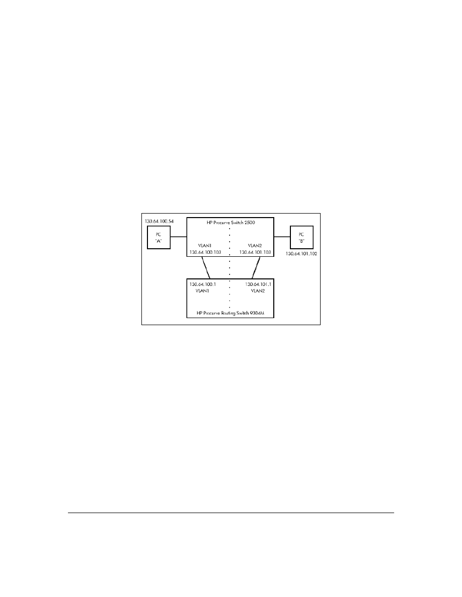
75
Q8: Is Gigabit Ethernet auto-negotiation the same as Plug-n-Play?
A:
No. By the time the IEEE issued the 802.3z specification, they knew about the 10/100Mbps auto-
negotiation problem . (See the FAQ "Is 10/100Mbps auto-negotiation the same as Plug-n-Play?"—page
73.) To prevent it, 802.3z auto-negotiation requires that, if one side of a connection is configured to
auto-negotiate, the other side must also auto-negotiate if the connection is to come up. In other words,
if a switch is configured to auto-negotiate and its attached end node is configured to, say, 1000Mbps/
full-duplex, the 803.2z spec requires that the switch NOT allow the link to come up.
Q9: What is the recommended way to connect multiple VLANs between a routing switch
and a layer 2 switch?
The diagram below illustrates the question.
A:
The following HP switches provide VLANs and have a single MAC/Ethernet address (filtering)
table: Switch 800T, 2000, 1600M, 2400M, 2424M, 2512, 2524, 4000M, 8000M. In the diagram above we
show a Switch 2500, but the following discussion applies to all of the switches listed in the previous
sentence. The HP Procurve Routing Switch 9304M, 9308M, or 6308M-SX, as a default gateway, has a
single MAC address (for all of its VLANs) if using virtual Ethernet interfaces. In the diagram above
we show a 9304M, but this could be a 9308M or 6308M-SX as well.
Let's consider PC "A" attempting to send an IP packet to PC "B". PC "A" will send the 2500 a packet
with the 9304M's MAC address in the destination field. If the 2500 has not yet learned this MAC
address, the 2500 will flood the packet out all of its VLAN1 ports, including the VLAN1 link to the
9304M. The 9304M will then route the packet toward PC "B" via its link with the 2500's VLAN2
connection. The 2500 will enter the 9304M's MAC address into its MAC address table as located in
VLAN2. The 2500 will also forward the packet to PC "B".
Let's consider a second packet that PC "A" sends to PC "B". PC "A" sends the packet, again addressed
to the 9304M's MAC address, to the 2500. The 2500 will check its address table and find that the 9304M
appears to be located on VLAN2. Since the 2500 believes that this MAC address is not located on
VLAN1, the switch will discard the packet.
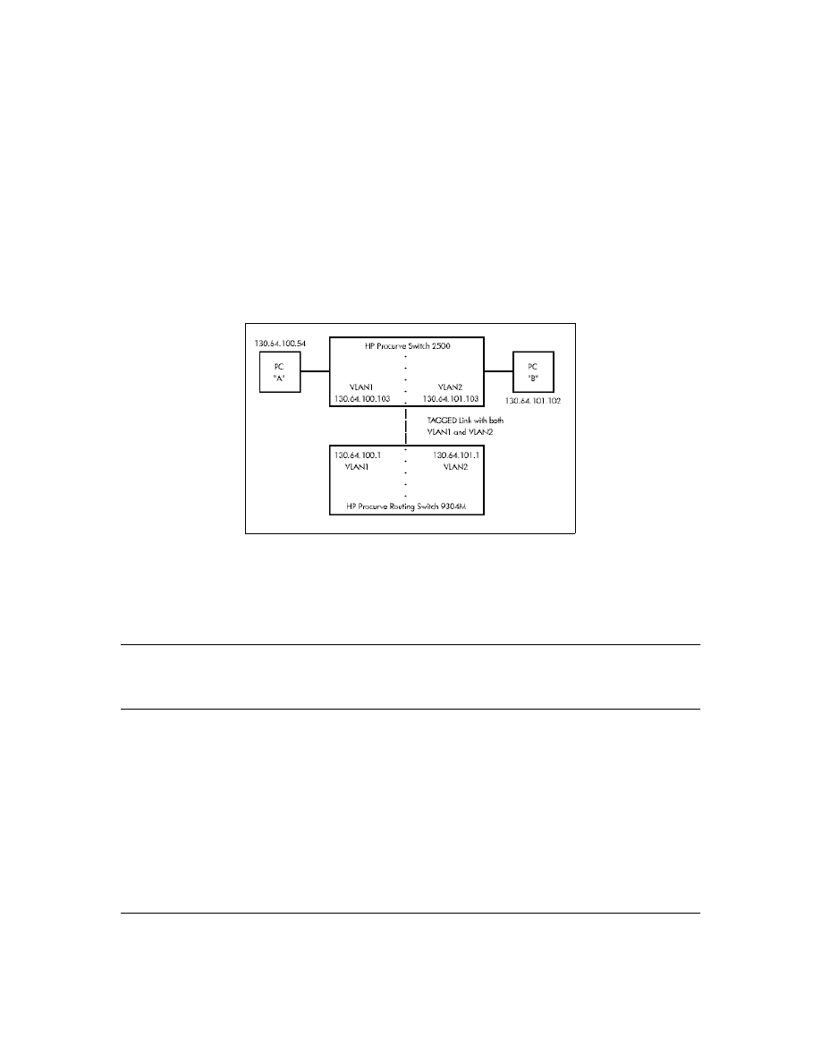
76
Later, when the 9304M transmits a packet to the 2500 via the VLAN1 link, the 2500 will update its
address table to indicate that the 9304M’s MAC address is located in VLAN1 instead of VLAN2. As
you can see, the 2500’s location information for the 9304M’s MAC address will vary over time between
VLAN1 and VLAN2. For this reason, some packets directed through the 2500 for the 9304M’s MAC
address will be discarded. Performance may appear to be poor or connectivity may appear to be
broken.
To avoid this issue, simply use one cable between the 2500 and the 9304M instead of two, making
sure that the two VLANs use tags on that link, as shown below.
Updates and Corrections for the Management and
Configuration Guide
This section lists updates to the Management and Configuration Guide (p/n 5969-2354; August 2000)
that was shipped with your Series 2500 switch.
Time Protocol Changes
Because the switch now offers both TimeP and SNTP (Simple Network Time Protocol) as time
synchronization methods, the TimeP configuration information on pages 5-3 through 5-10 has
changed. See “New Time Synchronization Protocol Options” on page 43.

77
Error in Command Shown for Viewing the Current Configuration Files
On page C-4, the manual incorrectly states that show
startup-config displays the current startup-config
file. Instead, the following is true:
■
show config: Displays a listing of the current startup-config file.
■
show run
: [Same as show config run, below. See R.S. doc.]
■
show config run: Displays a listing of the current running-config file.
■
write terminal: Displays a listing of the current running-config file.
Change in Command Line Operation
For the (port) Interface and VLAN commands, the command line accepts only one parameter at a
time. For example, for port 1, you would use either of the following two command sets to configure
duplex, flow control, and broadcast limit (instead of combining them all in one command).
At the Interface Context Level
HP2512(eth-1)# enable speed-duplex auto
HP2512(eth-1)# enable flow-control
HP2512(eth-1)# enable broadcast-limit 50
At the Global Configuration Level
HP2512(config)# int e 1 enable speed-duplex auto
HP2512(config)# int e 1 enable flow-control
HP2512(config)# int e 1 enable broadcast-limit 50
This change affects the following commands:
Interface
Commands
VLAN Commands
broadcast-limit
disable
enable
flow-control
lacp
monitor
speed-duplex
unknown-vlans
forbid
tagged
untagged

78
Restoring the Factory-Default Configuration
Page 11-20 in the Management and Configuration guide incorrectly implies that the
erase startup-config
command clears passwords. This command does reset the switch to its factory-default configuration,
but does not remove any user names or passwords (Manager or Operator) configured in the switch
.
To remove user names and passwords, do any one of the following:
■
Execute the
no password
command in the CLI.
■
Select the
Delete Password Protection
option in the "Set Password" menu screen.
■
Press and hold the Clear button on the switch for one second.
■
Restore the factory-default configuration by using the Clear/Reset button combination, as
described under "Restoring the Factory Default Configuration" in the "Troubleshooting"
chapter of the Installation and Getting Started Guide you received with the switch.
Incomplete IP Multicast (IGMP) Filtering Data
The Note on page 9-92 in the Management and Configuration Guide states that "IGMP requires an
IP address and subnet mask for any VLAN used for IGMP traffic." This is no longer true. See “New:
IGMP Now Operates With or Without IP Addressing” on page 64.
The second paragraph in the note on page 9-101 in the Management and Configuration Guide
provides incomplete data on the "well-known" or reserved IP multicast addresses that IGMP does
not filter in the Series 2500 switches. See “The Switch Excludes Well-Known or Reserved Multicast
Addresses from IP Multicast Filtering” on page 70 of this document.
GVRP Does Not Require a Common VLAN
Delete the note at the top of page 9-78 in the Management and Configuration Guide. GVRP does
not require a common VLAN (VID) connecting all of the GVRP-aware devices in the network to carry
GVRP packets.
Incomplete Information on Saving Configuration Changes
Using the CLI to make a configuration change to the running-config file, then going to the Menu
interface and making another configuration change, and then executing the Menu interface
Save
command saves all of your changes to the startup-config file. (At this point, the startup-config file
and the running-config file will have identical configurations, and will contain all of the changes that
you made in both interfaces.)
The second paragraph of the Note on page C-6 in the Management and Configuration Guide states
that "Using the Save command in the menu interface will not save a change made to the running
config by the CLI
." This statement is true where you:
1.
Make configuration changes in the CLI
2.
Move to the Menu interface, but make no configuration changes while using the Menu interface.

79
3.
Execute the
Save
command in a Menu interface screen.
However, the statement is not true if you make a configuration change in the Menu interface before
going to step 3, above. See also "Switch Memory Operation" on page 70.
Update to Information on Duplicate MAC Addresses Across VLANs
On page 9-75 of the Management and Configuration Guide , the following information replaces the
text in the fourth bullet from the top and the Note:
Duplicate MAC addresses on different VLANs are not supported and can cause VLAN operating
problems. These duplicates are possible and common in situations involving Sun workstations with
multiple network interface cards, with DECnet routers, the Procurve routing switches (9304M,
9308M, and 6308M-SX), and with certain Hewlett-Packard routers using OS versions earlier than
A.09.70 where any of the following are enabled: IPX, IP Host-Only, STP, XNS, DECnet, and possibly
others. When in doubt, ask your router vendor under what conditions, if any, the router uses the same
MAC address on more than one interface. Regarding the HP Procurve routing switches, see the FAQ
"Q8: What is the recommended way to connect multiple VLANs between a routing switch and a layer
2 switch?" on page 75.
N o t e
Duplicate MAC addresses are likely to occur in VLAN environments where XNS and DECnet are
used. For this reason, using VLANs in XNS and DECnet environments is not currently supported.
On page 11-10 of the Management and Configuration Guide, under "Duplicate MAC Addresses
Across VLANs", the text suggests that duplicate MAC addresses on separate VLANs can cause VLAN
operating problems. However, duplicate MAC addresses on different VLANs may cause operating
problems that have no apparent connection to VLAN operation. Thus, in the paragraph under
"Duplicate MAC Addresses Across VLANs", delete the word "VLAN" from the first sentence. That is,
the sentence should be: "Duplicate MAC addresses on different VLANs are not supported and can
cause operating problems."
Incorrect Command Listing for Viewing Configuration Files
On page C-4 of the Management and Configuration Guide, under "How To Use the CLI To View the
Current Configuration Files", the
show startup config
command is incorrect. Use the following "
show
"
methods for listing configuration files:
■
show config
: Displays the startup-config file.
■
show config run
: Displays the running-config file.
(The
write terminal
command also displays the running-config file.)

80
The
show config
,
show config run
, and
write terminal
commands list the following configuration data:
■
Daylight Time Rule setting
■
Hostname (system name)
■
SNMP server community name and status
■
The default VLAN and its IP address setting
■
Any other configuration settings that differ from the switch’s factory-default configuration.
Incorrect Information for Restoring the Factory-Default Configuration
The text on page 11-20 in the Management and Configuration Guide implies that the
erase startup-
configuration
command for restoring the factory-default configuration clears any usernames and
passwords configured in the switch. The only method for simultaneously resetting the switch to the
factory-default configuration and removing any usernames and passwords configured in the switch
is to use the Clear/Reset button combination described under "Clear/Reset: Resetting to the Factory-
Default Configuration" at the bottom of page 11-20.
New and Corrected Information on Primary VLAN Usage
The second bulleted item on page 9-54 incorrectly states that "The switch reads DHCP responses on
the primary VLAN instead of on the default VLAN." The switch reads DHCP (and Bootp) responses
received on all VLANs. The restriction is that the switch only honors default gateway addresses,
TimeP server addresses, and IP TTL values learned from DHCP or Bootp packets received on the
primary VLAN.
Also on page 9-54, add the following item to the bulleted list:
■
When TimeP is enabled and configured for DHCP operation, the switch learns of TimeP
servers from DHCP and Bootp packets received on the primary VLAN.
Misleading Statement About VLANs
On page 9-56 in the Management and Configuration Guide, the last sentence in item 1 implies that by
default the switch is configured for eight VLANs. The sentence should read as follows:
"By default, VLAN support is enabled to support up to eight VLANs, and the switch is configured for
one VLAN (the default VLAN). By changing the Maximum VLANs to support parameter, you can
configure up to 29 VLANS."

81
This page is intentionally blank.

82
This page is intentionally blank.

83

© 2001 Hewlett-Packard Company. All
rights reserved. Reproduction, adaptation,
or translation without prior written permis-
sion is prohibited except as allowed under
the copyright laws.
HP Part Number: 5969-2371
Edition 1, January 2001
*5969-2371*
The information contained in this document is subject to change
without notice.
Document Outline
- Software Update F.02.xx Release Notes for the HP ProCurve Series 2500 Switches
- Notices
- Contents
- TACACS+ Authentication for Centralized Control of Switch Access Security
- Series 2500 Switch Authentication Options
- Terminology Used in TACACS Applications:
- General System Requirements
- TACACS+ Operation
- General Authentication Setup Procedure
- Configuring TACACS+ on the Switch
- How Authentication Operates
- Using the Encryption Key
- Controlling Web Browser Interface Access When Using TACACS+ Authentication
- Messages
- Operating Notes
- Troubleshooting TACACS+ Operation
- All Users Are Locked Out of Access to the Switch
- No Communication Between the Switch and the TACACS+ Server Application
- Access Is Denied Even Though the Username/Password Pair Is Correct
- Unknown Users Allowed to Login to the Switch
- System Allows Fewer Login Attempts than Specified in the Switch Configuration
- CDP
- Introduction
- CDP Terminology
- General CDP Operation
- Configuring CDP on the Switch
- Effect of Spanning Tree (STP) On CDP Packet Transmission
- How CDP Selects the CDP Neighbor’s IP Address When Multiple VLANs Are Present
- CDP Neighbor Data and MIB Objects
- Operating Notes
- Troubleshooting CDP Operation
- New Time Synchronization Protocol Options
- TimeP Time Synchronization
- SNTP Time Synchronization
- Overview: Selecting a Time Synchronization Protocol or Turning Off Time Protocol Operation
- SNTP: Viewing, Selecting, and Configuring
- TimeP: Viewing, Selecting, and Configuring
- SNTP Unicast Time Polling with Multiple SNTP Servers
- SNTP Messages in the Event Log
- Operation and Enhancements for Multimedia Traffic Control (IGMP)
- Switch Memory Operation
- Port Security: Changes to Retaining Learned Static Addresses Across a Reboot
- Username Assignment and Prompt
- Series 2500 FAQs from the HP Procurve Website
- Updates and Corrections for the Management and Configuration Guide
- Time Protocol Changes
- Error in Command Shown for Viewing the Current Configuration Files
- Change in Command Line Operation
- Restoring the Factory-Default Configuration
- Incomplete IP Multicast (IGMP) Filtering Data
- GVRP Does Not Require a Common VLAN
- Incomplete Information on Saving Configuration Changes
- Update to Information on Duplicate MAC Addresses Across VLANs
- Incorrect Command Listing for Viewing Configuration Files
- Incorrect Information for Restoring the Factory-Default Configuration
- New and Corrected Information on Primary VLAN Usage
- Misleading Statement About VLANs
- Notices, Part Number, and Edition
Wyszukiwarka
Podobne podstrony:
F 02 11 Release Notes
FISC Misc 13 02 Release Unclass Opinion Parts
CDM 2 08 02 Release Info
F 04 08 Release Notes
P2 53 5 Release Notes ISTA P ENG
SK6211 090411 Release Notes
191 07 Win7 Desktop Release Notes
DWL G700AP v2 31 release notes
185 85 WinXP GeForce Release Notes
videocapture release notes DVI7MFSN26EW6G2L7YD2U6M35ZLWDV3TQXDXQII
vegasvideo release notes WSFB47OPARMFHILPMPIR37S3HSPX53U3EJNQK4I
F 04 08 Release Notes
P2 53 5 Release Notes ISTA P ENG
Release Notes PC SDK 5 13
release notes 2 0 6 ru
BC HCE v2 70 Release Notes
Release Notes RobotWare Machining FC GUI v5 13
więcej podobnych podstron