
Release Notes
Version 2.70
November 2012

Corporate Office
Trimble Navigation Limited
Engineering and Construction Division
935 Stewart Drive
Sunnyvale, California 94085
U.S.A.
Phone: +1-408-481-8000
Toll free (in USA) +1-800-874-6253
Fax: +1-408-481-7744
www.trimble.com
Copyright and Trademarks
© 2005-2012, Trimble Navigation Limited.
All rights reserved.
The Globe & Triangle logo and Trimble are
trademarks of Trimble Navigation Limited.
All other trademarks are the property of
their respective owners.
CAT, CATERPILLAR, their respective
logos, AccuGrade and Caterpillar Yellow, as
well as corporate and product identity used
herein, are trademarks of Caterpillar and
may not be used without permission.
This application incorporates Teigha
®
software pursuant to a license agreement
with Open Design Alliance. Teigha
®
for
.dwg files. Copyright
©
2003-2011 by Open
Design Alliance. All rights reserved.
Release Notice
These are the release notes for version 2.70
of Business Center - HCE software.

Release Notes
1
Product Overview
Welcome to the version 2.70 update of
Business Center - HCE
, one of the suite of
office software products contributing to Trimble’s Connected Site™ solutions.
This software is designed, in part, for construction contractors and engineers
managing data for a connected construction site, and employing Trimble Grade
Control Systems (GCS), Paving Control Systems (PCS), and Site Positioning
Systems (SPS) that use Site Controller Software (SCS), including the Tablet
Edition.
Business Center - HCE facilitates the management of data for multiple field crews
operating on a job site. You can import, review, and analyze digital designs, and
then assign, manage, and track that information through the lifecycle of a
construction project. Ask your dealer for the complete list of current features that
come in the core product and in licensed add-on modules.
Languages
The program and its documentation are available in these languages:
British English
Chinese (Simplified)
Dutch
French
Finnish
German
Italian
Japanese
Portuguese (Brazil)
Russian
Spanish
Swedish
US English

Release Notes
2
New in Version 2.70
Ease-of-use Features
Recent Commands - You can now access the last five commands you opened
on the right side of the right click context menu. The number of recent
commands that appear on the context menu can be increased to 20.
(See the
Context Menu Options
help topic.)
Command Pane persistence – The command pane no longer closes with the
[ESC]
key. This improves the experience for users who wish to enter
commands from the keyboard and eliminates the resizing of the graphics area
when ending one command and starting another. The command pane can be
closed by selecting the
Close
icon for the pane.
Space bar repeats the last command – When the command pane is open,
pressing the space bar repeats the last command.
(See the
Run the Previous Command
help topic.)
Run Last Command - Using a shortcut key, you can now use
Run Last
Command
to quickly launch the previously-run command or to run a command
multiple times in a row without having to keep the command pane open.
(See the
Run the Previous Command
help topic.)
Context menu enhancements – Additional related commands have been
added to many context menus so the commands you need are easier to access.
Simplified default toolbar – The default toolbar has been shortened to
provide more graphics space by presenting the commands most used
throughout the program. Many users have found it easier to have fewer icons
to learn, select commands from the menus, and make specific toolbars as
needed. Users may, of course, still load the previous full toolbars or make
their own configurations. (See the
Set a Menu Layout
help topic.)
Layer warning - When you are specifying a layer for a new object (in the
Command Pane
), a warning now appears if the layer you choose is hidden in all
of your views.
Layer persistence - For most commands, the layer you selected the last time
you used the command now persists so it is the default layer the next time you
use the command.
Toggle background color - You can now use the
Toggle Backgorund Color
icon
on the
Status bar
to quickly invert the background color (black or white) for all
graphic views. (See the
Status Bar
or
Startup and Display Options
help topic.)
Usability enhancements - Many small improvements have been made to
increase the program's ease-of use.
Performance-related Features
Graphics performance – Many improvements have been made in the
management and speed of the graphics. These improvements affect how
images and point cloud data are stored and displayed.

Release Notes
3
View filter enhancements:
Quick filters- In the
View Filter Manager
, you can now use two options to
quickly filter your data in a graphic view:
View only layers of selected objects
and
Hide layers of selected objects
. In addition, you can now cull your Layers
list in the manager by clicking
Hide non-visible layers
.
(See the
View Filter Manager Options
help topic.)
Speed improvement – When toggling layers on and off within the
View
Filter Manager
, the drawing of the graphics has been optimized to be much
faster.
Surface properties in View Filter Manager – You can now access
properties for any surface from the
View Filter Manager
by right-clicking the
surface name and selecting
Properties
in the context menu.
Toggle layer visibility and selectability – In the
View Filter Manager
, you
can now select multiple layers and press
[spacebar]
to toggle their visibility
on/off. In the
Advanced View Filter Settings
dialog, you can now select
multiple layers in the
Selectable
column and press
[spacebar]
to toggle their
selectability on/off.
Data Exchange-related Features
Nordic software file import (new formats and enhancements) - You can now
import many more file types created in SBG Geo™, ViaNova Novapoint, and
Mesta Anleggspakken and WinAnfelt software, including .lmd, .geo, .apd, .gt,
.vgp, and .xml (for tunnels). In addition, many of the existing importers for
Nordic software formats (.kof, .lin, .nyl .prf, .pxy, .sec, .tit) have been
improved. (See the
Import Nordic Data Exchange Files
help topic.)
MicroStation file import (enhancements) - The current DGN importer
(DGNDirect) has been replaced with the latest TeighaNET library, which is
available in both 32-bit and 64-bit versions.
(See the
Import MicroStation Files
help topic.)
SketchUp file import - Import points, lines, and surfaces in a SketchUp file
(.skp) from Trimble SketchUp. (See the
Import SketchUp Files
help topic.)
CAiCE file import – You can now import horizontal alignment and cross-
section data in CAiCE file format (.txt)., the standard for the Georgia
Department of Transportation.
SketchUp file export - Export points, lines, and surfaces to a SketchUp file
(.skp) that can be opened in
Trimble SketchUp
.
(See the
Export SketchUp Files
help topic.)
Point-related Features
Convert CAD Points – You can now use the
Convert CAD Points
command to
make survey points (with latitude, longitude, height , and quality) from
imported CAD points. (See the
Convert CAD Points to Points
help topic.)

Release Notes
4
Line-related Features
Create Circle - You can now use the
Create Circle
command to draw a 360°
arc at a constant elevation. Using the auto-advance mode, you can quickly
create multiple circles with the same radius. (See the
Create a Circle
help topic.)
Surface-related Features
Surface Info Report enhancements - In the
Surface Information Report
, you
can now choose to include information on the surface's area sorted by
elevation/depth range and by slope range. In addition, you can specify a
boundary in the report to limit the portion of the surface on which you get
statistics. (See the
Run a Surface Information Report
help topic.)
Drape Objects on Surface - In addition to polylines and linestrings, you can
now use the
Drape Object on Surface
command to vertically project points onto a
surface. A draped point is dependent on the location (X,Y or latitude,
longitude) of the reference point and the surface's topography. (See the
Drape a
Point of Line on a Surface
help topic.)
Offset a Draped Line - Once you have created a draped line, you can use the
Properties
pane to add a horizontal offset from the reference line to the draped
line and to add a vertical offset from the dependent surface to the draped line.
(See the
Drape a Point of Line on a Surface
help topic.)
Surface shadows - You can now show/hide a surface's shadows in the
Properties
pane.
Surface Name and Slope in the Coordinates scroll - In the
Coordinates
scroll, you can now choose to show the slope of any surface triangle and the
name of the surface you are hovering over in the
Plan View
.
Surface properties from View Filter Manager – You can now access
properties for any surface from the
View Filter Manager
by right-clicking the
surface name and selecting
Properties
in the context menu.
Surface transparency – You can now control the transparency of a surface in
the
Properties
pane for the surface. This enables you make objects, such as an
image of a site plan, visible behind the surface.
Drape cut/fill colors on Finished Design surface – In the
Properties
pane for
a cut/fill map, you can now set
Drape surface
to
Yes
to display the cut and fill
colors on the surface selected as the
Final
surface in the
Create Cut/Fill Map
command.
Corridor-related Features
Icon for dependent corridor templates - Corridor templates that were
copied from other templates or that reference other templates are now
indicated by a distinct icon in the
Project Explorer
.
(See the
Create Corridor Templates
help topic.)

Release Notes
5
Slope for corridor template instructions - You can now use
Project Settings
(
Project > Project Settings > View > Corridor Template View > Instruction slope
) to
show/hide slope values (in % or ratio) for the active instruction in a corridor
template. (See the
Edit and Delete Corridor Template Instructions
help topic.)
Corridor template instructions by material layer - You can now use the
View Options
within the
Corridor Template View
to filter the view so it shows only
the instructions for a specific material layer.
(See the
Edit and Delete Corridor Template Instructions
help topic.)
Alignment Name in the Coordinates scroll - In the
Coordinates
scroll, you
can now choose to show the name of the alignment you are hovering over in
the
Plan View
.
NSW Spiral type – The
Australian NSW
(New South Wales) cubic parabola
spiral type for railway transition curves is now supported in alignments.
Drafting-related Features
Create Alignment Labels - Use the
Create Horizontal Alignment Labels
command to display values for stations, station equations, horizontal
alignment (HAL) points, and abbreviations for other key points along an
alignment. These values will be included in output when you print views that
show them. (See the
Label an Alignment
help topic.)
Area by elevation in legend - You can now use the
Properties
pane to convert
the legend to a table showing the area for each surface elevation band
represented in the legend. (See the
Add a Legend to a Surface or Map
help topic.)
Copy plotbox image to clipboard - You can now copy a screen image of a
plotbox's contents to the clipboard so it can be pasted into another program,
such as
Trimble SketchUp
.
(See the
Create a Plotbox and Print its Contents
help topic.)
Image-related Features
Image transparency - You can now specify the transparency on an image in
the
Properties
pane for the image.
Copy graphic view image to clipboard - You can now copy a screen image
of a graphic view's contents to the clipboard so it can be pasted into another
program, such as
Trimble SketchUp
.
(See the
Create a Plotbox and Print its Contents
help topic.)
Data Prep-related Features
Explode Object enhancements - You can now use the
Explode
command to
break apart additional object types that contain components that you want to
move, modify, delete, or export individually. Objects that you can explode
include blocks, corridors, cut/fill map grids, surface elevation grids, surface
ties, contour lines, and draped lines. When you explode a cut/fill map, CAD
points are created at the tick mark locations. When you explode a densified
corridor, the resulting linework reflects the densification (
with rare exceptions).

Release Notes
6
Site Takeoff-related Features
A major change has been made in how site improvements are assigned. The new
method described below is much faster, eliminates many user errors and provides
instant feedback of how the improvement will be applied. Although the previous
method is still supported, it is highly recommended that users review the updated
Takeoff training guides and adopt the new method.
(See the
Understanding Area-based Site Improvements
help topic.)
Assign Site Improvement - You can now use the
Assign Site Improvements
command to create area-based site improvements more easily and with greater
certainty that they are calculating the intended area. In addition, the slope area
(not just the planimetric) is now calculated for the site improvement areas
assigned using this method.
(See the
Assign Site Improvements to Takeoff Layers
help topic.)
The benefits of this new method include:
When site improvements abut, you no longer need to have coincidental
boundaries. A single line can serve as a boundary between site
improvements. This can eliminate issues caused by small gaps and
overlaps in the individual boundaries of adjoining site improvements.
You no longer have to make closed areas to contain site improvements.
Closed areas can still be used automatically or manually.
You can use 2D and 3D linework.
You get immediate feedback and shading of the resulting area.
If you pick a point and the area is not enclosed, you get a warning.
Minor drafting imperfections, such as gaps that keep multiple lines from
forming the intended enclosed area, can be ignored via a tolerance,
allowing the site improvement to be formed in spite of that issue.
Additionally, such data imperfections have become clear, allowing you to
fix those problems as a part of a data preparation process.
Copying materials and site improvements - You can now copy materials
and site improvements within a category or library or from either library to the
other library by selecting an item or category and dragging-and-dropping it to
a new location.
(See the
Copy from the External Library to Your Project Library
help topic.)
Distinguish between earthen materials - You can now distinguish between
earthen materials for mass earthworks and those for select operations in
Material and Site Improvement Manager
when you are preparing to do takeoff
calculations. (See the
Create and Edit Earthen Materials
help topic.)
Earthen (Mass earthworks) Materials - Earthen materials found within
the project site’s subsurface earthen material strata or off-site borrow pits
that contribute to the analysis of mass earthworks.
Earthen (Select) Materials - Earthen materials of a select nature that may
be required for specific purposes. These include mined, manufactured or
otherwise processed materials.

Release Notes
7
Drillhole display - Now each drillhole's name is shown and the point
symbol's size has been increased in graphic views.
Perpendicular offset for site improvements - You can now specify whether
you want to use vertical or perpendicular offset for each area-based site
improvement (defaults to perpendicular). This enables you to calculate site
improvement quantities based on perpendicular offsets.
(See the
Area Site Improvement Options
help topic.)
Takeoff Report enhancements: (See the
Run a Takeoff Report
help topic.)
Separated units - Supplemental measurement units have been separated
from actual units, and units have been separated from quantities. This
enables you to cut-and-paste the values elsewhere.
Slope lengths and areas - The report can now show slope lengths for
linear site improvements (for which the
Slope length
quantification basis is
used in the definition of the site improvement) and slope areas for area-
based site improvements (for which the
Surface area
quantification basis is
used).
Site Mass Haul-related Features
Create Earthworks Site - You can now use the
Create Earthworks Site
command to create a borrow pit or waste site at a known location for a site
mass haul. The
Site Mass Haul Analysi
s command can then be used to determine
the optimal way to distribute earthworks. If a haul road connects the
earthworks site to the construction site, the mass haul analysis will consider
hauling material to and from this site.
(See the
Create Earthwork Sites
help topic.)
Create Haul Road – Use the
Create Haul Road
command to connect
earthworks sites to the construction site. A valid haul road can now have an
end point outside of a zone.
(See the
Create and Edit Haul Roads for Mass Haul
help topic.)
View balance properties – In the
Plan View
, you can now select a balance
between two zones, and view the balance details on the balance page. Balance
details include the volume of material moved and the cost to move the
material. (See the
Understanding Balancing in Mass Haul
help topic.)
Haul road costs - Costs for haul roads are now displayed and entered as
cost/volume unit/mile or cost/volume unit/kilometer.
(See the
Create and Edit Haul Roads for Mass Haul
help topic.)
Haul routes - Route calculations and object properties have been improved
for site mass haul.

Release Notes
8
Corridor Mass Haul-related Features
Show grade points - In the properties of a corridor mass haul analysis, you
can now select
Yes
in the
Show grade points
box to display grade points on the
usable ordinate in the
Mass Haul Diagram
. Maximum grade points (blue) display
where the mass haul changes from having excess cut to excess fill. Minimum
grade points (red) display where the mass haul changes from having excess
fill to excess cut.
(See the
View and Interpret a Corridor Mass Haul Diagram
help topic.)
Refresh button – In the
Mass Haul Diagram
, you can now easily refresh the
mass haul analysis by clicking the
Refresh
button.
(See the
Refresh a Corridor Mass Haul Analysis
help topic.)
Balanced Cut/Fill Zones – When a corridor mass haul is balanced, the
balanced cut/fill zones now appear on the corridor in the
Plan View
. In the
Corridor Mass Haul Diagram
, when you select a balance line, the footprint of the
balanced cut/fill zone is highlighted in the
Plan View
.
(See the
Analyze Mass Haul Needs for a Corridor
help topic.)
Haul road costs - Costs for haul roads are now displayed and entered as
cost/volume unit/mile or cost/volume unit/kilometer.
(See the
Create and Edit Haul Roads for Mass Haul
help topic.)
Mass haul ordinates in the View Filter Manager - Once you have created a
corridor mass haul and a
Corridor Mass Haul Diagram
, a
Mass Ordinates
group
appears in the
View Filter Manager
so you can show/hide your ordinates for haul,
cut, fill, and material volumes in the diagram.
(See the
View and Interpret a Corridor Mass Haul Diagram
help topic.)
Field Data-related Features
Support for SCS900 version 3 - You can now export and re-import field data
files to version 3 of SCS900.
Export sub-alignments to GCS Machines - You can now include named
sub-alignments when you export to GCS machines. This enables you to see a
corridor's named cross-section nodes in GCS900.
(See the
Export GCS Machine Job Site Design Files
help topic.)
VisionLink and TCC Login Pages - You can now access the
Connected
Community
(TCC) and
VisionLink
from the
Tools
menu in the program. (See the
VisionLink
and
Connected Community
help topics.)

Release Notes
9
Survey-related Features
Trimble R10 receiver
RTK tilt - Import RTK tilt magnitude and quality data, including the tilt
calibration date, from a Trimble Access Job or JobXML file and display it in
the
RTK Vector Properties
pane and
Vector Spreadsheet
. Specify tilt tolerances in
Project Settings
. Export RTK tilt data using the Custom Exporter.
PPK tilt - Import PPK tilt magnitude and quality data, including the tilt
calibration date, from a combination of a Trimble Access Job or JobXML file
and a T02 file and display this information in the
PPK Vector Properties
pane
and
Vector Spreadsheet
. Specify tilt tolerances in
Project Settings
. Export PPK tilt
data using the Custom Exporter.
RTCM age - View "RTCM age" as a property of an RTK vector in the
RTK
Vector Properties
pane and
Vector Spreadsheet
. Export RTCM age data using the
Custom Exporter. (Radio Technical Commission for Maritime Services
(RTCM) is an international communication/corrections format that is not
manufacturer-specific.)
Trimble xFill observations - Import Trimble Access Job or JobXML files
containing xFill observations. xFill observations will import as RTK vectors
with solution type "xFill" and can be processed, reported, and exported along
with standard RTK observations.
QZSS - Import raw GNSS data that includes observables from the QZSS
constellation, select to use or not use data from satellites in this constellation
in baseline processing, view QZSS tracking in the session editor, and review
QZSS processing in the
Baseline Processing Report
.
Images and scanned data
Import/export point cloud data - Import and export point cloud data in a
variety of popular formats (.e57, .las, .pts, .ptx, .xyz, and .yxz).
(See "
Import Point Cloud Files
" and "
Export Point Cloud Files
" in the online Help.)
3D walk-through – With a 3D view open, use the new
Walk Through
command
to simulate walking through 3D data, including point cloud data. Use the
interface pane, mouse, or keyboard to control your position, speed, movement,
view direction, and elevation. (See "
Walk Through View
" in the online Help.)
Station view field-of-vision indicator - When using the
Plan View
, view
which
Station Views
are open and in which direction they are facing. Control
the size and transparency of the status cones in
Tools > Options >
Photogrammetry
. (See "S
tation View (Referenced Images)
" in the online Help.)
Frame rate - Models display more smoothly and the screen refreshes more
quickly due to an enhanced frame rate, resulting in a more seamless viewing
experience when working with large data sets.

Release Notes
10
Features data
Update feature codes - Feature codes are automatically updated when you
modify processed features. There is no need to undo and redo feature code
processing to update the codes.
(See "
Process Feature Codes
" in the online Help.)
Corridors
RXL spiral support - Import and export Bloss and Cubic spirals and Korean
Cubic Parabolas.
Data exchange support
Export data to ArcGIS 9.3.1 - Use the Geodatabase XML exporter to export
data to ArcGIS 9.3.1.
AutoCAD units export - Export AutoCAD files with specified units.
GeoXR monopole - Import and process data gathered using the new Trimble
GeoXR monopole.
Spectra Precision Survey Pro 5.2 - Import files from Spectra Precision's
Survey Pro 5.2. Also, export lines and alignments to Survey Pro.
FAST Survey - Import FAST Survey formatted files with local coordinate
systems support.
General
Laser observations - View laser observations in the
Optical Spreadsheet
.
Check-for-updates MSMs - View installed MSMs included in the "Installed
Version" list in the
Check for Updates
dialog so you do not need to re-install.
Documentation
Enterprise Deployment Guide -The guide has been updated to include
instructions for deploying software updates using Msiexec.exe.
Additional Workflow Wizards - You can now use new workflow guides,
wizards, and help topics to understand and work through the workflows for
site mass haul, corridor data prep, corridor mass haul, and others.
(See the
Follow Workflow Guides
help topic.)
Miscellaneous Features
Warranty expiration alert - You are now alerted to your impending
warranty expiration data 60, 30, and 5 days before it happens.
(See the
Register and Warranty this Software
help topic.)
Microsoft® Windows® 8 - The software will run on the Windows 8
operating system.
Release Notes
11
Enhancements from the BC -HCE 2.61 and 2.62 Patches
Printing and plotting – When printing or plotting (in landscape orientation) a
plotbox that contains an image, the image is no longer stretched. In addition,
any gridlines within the plotbox now appear in the correct locations when
printed or plotted.
New snaps - Three snap commands have been added:
Station from Segment Snap enables you to calculate a station value from
a point along a specific segment of an alignment or line.
(See the
Station from Segment Snap
help topic.)
Bearing of Segment Snap enables you to specify a bearing by picking a
segment with the desired bearing in the
Plan View
.
(See the
Bearing of Segment Snap
help topic.)
Length of Segment Snap enables you to specify a length or distance by
picking a segment with the desired length in the
Plan View
.
(See the
Length of Segment Snap
help topic.)
Note: You can also press
[Shift]
and click a line segment when you are in either a
bearing or distance box to derive the appropriate value from the segment.
Intersection of Lines snap – When snapping to the ‘intersection’ of two
lines, if the lines do not actually touch, the intersection is computed by
projecting one or both of the lines to their nearest intersection.
(See the
Intersection of Lines Snap
help topic.)
Edit Linestring - When you are editing a linestring (using the
Edit Linestring
command), the segment you are editing is highlighted in both the
Plan View
and
3D View
. In addition, you can now pick linestring segments and vertical
points of intersection (VPIs) in the
3D View
.
Offset Line - The command’s boxes have been rearranged and an auto-
advance option has been added to the offset boxes. These improvements allow
you to simply pick the line to offset and then the side on which to create the
offset line once you have specified the name, layer, and offset distances; this
helps you to create multiple offset lines more efficiently.
Float View - You can now separate (‘float’) browser page views (such as the
Start Page
,
Workflow Guides
, and reports) from your program window so you
can move them onto a second monitor.
Trim/Extend Lines – If a line crosses over itself, you can now trim the line
back to the point at which it self-intersects by picking the line as its own
bounding line.
Line highlighting – Selected lines now highlight consistently in all graphic
views (using the highlight color and line width defined in program options).
CAD block import – When you convert blocks to 3D points during a
.dxf/.dwg file import, points are no longer created for blocks at 0,0; often,
these were invalid points geographically separated from your actual data.

Release Notes
12
Corridor mass haul – Balance lines for a corridor mass haul analysis now
include a
No haul
property to indicate earthwork volumes that are neither
balanced nor cross-hauled. This will occur in cases where at one station there
is a distributed import/borrow that gets used as fill at that station (therefore
not altering the cumulative usable ordinate or being accounted for in the
balance volume).
Graphics performance – Rendering speed in the graphic views has been
improved for several functions, such as editing unusually long linestrings.
Create Linestring enhancements - When you are creating new segments at
the end of a linestring, you can now lock the
Elevation
box so that all
subsequent segments use the same elevation. This enables you to quickly
create a linestring by simply picking points in the
Plan View
(similar to the
Create Polyline
command).
Release Notes
13
Notes from the 2.60 Read Me File
Feature Definition Manager v2.10
There are no new issues at this time.
Business Center - HCE v2.60
Tours and tutorials - Due to their cumulative size, the tours, tutorials, and
sample data have been moved online to:
https://www.myconnectedsite.com/site/TrimbleHHCommunity/BC-
HCEToursandTutorials/
Tunnel Shape Editor
– A
Type
setting has been added for segment-based shapes.
It include these two options to accommodate users exporting a tunnel to
SCS900:
Profile
- Leave this as the default for segments that define the tunnel
walls and ceiling.
Floor
- For users exporting a tunnel to SCS900, select this for the two
segment end points that are intended to connect to the corridor surface
(the floor). These are typically the first and last rows in a
Segment
shape.
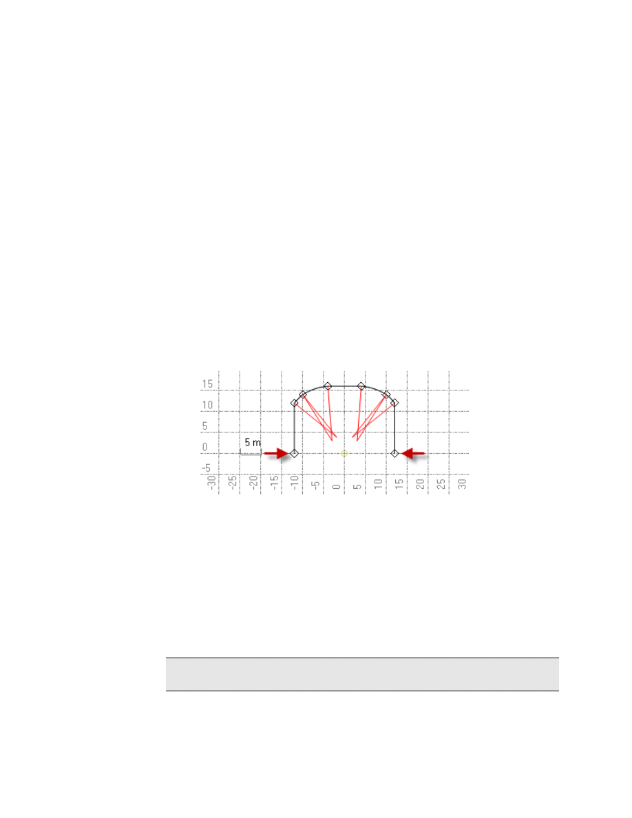
Create Tunnel Surfaces – This item was added to the Release Notes after
translation:
Use the
Create Tunnel Surface
command to build a radial surface from scanned
tunnel data (point clouds). Unlike other types of surfaces, a tunnel surface
allows vertices at the same X,Y, but different Z. The program achieves this by
internally 'unrolling' the scanned data using a coordinate system based on the
angle and distance from an alignment, creating the surface, and then re-rolling
the surface into the tunnel shape. For this reason, you need to specify an
alignment (HAL and VAL) and a vertical offset (radius center point) around
which the unrolling will occur to form the best surface possible.
Note: This command is unrelated to the commands in the tunnel creation
workflow.
Release Notes
14
System Requirements
The following computer configuration recommendations are based in part on
subjective evaluations in regard to what constitutes acceptable and desirable
performance. The configuration addressing minimum acceptable performance
should be used in assessing the suitability of a system that you already own. The
configuration addressing minimum desirable performance should be considered,
along with other factors related to intended usage, in making decisions leading to
the upgrading of your system or the purchase of a new system.
The subjective evaluation related to the assessment of a solution for minimum
desirable performance is based in part on consideration of incremental cost
factors, wherein additional advantage can be gained for little additional cost. As in
all matters leading to such purchasing decisions, consideration should be given to
future needs as both operating systems and application software are further
developed and computation power and storage capacity requirements continue to
increase. We can offer little guidance in predicting future trends, other than to
note the need to consider the recent past and to act accordingly.
For Recommended Performance:
Operating system:
Microsoft
®
Windows
®
XP (32-bit with Service Pack 3; 64-bit with
SP2), Windows Vista (with SP1), Windows 7, or Windows 8
Processor:
Dual-Core 1.80 GHz
Random access
memory:
2 GB or greater
Hard disk space
available:
5 GB
Graphics memory:
Mid-range, discrete graphics card with minimum 256 MB and support
for DirectX
®
9.0 (avoid integrated graphics if possible)
Monitor:
1024 x 768 or higher resolution with 256 colors
This assumes that your DPI setting is Normal (96 DPI) and that your
font size is also set to Normal.
I/O Ports:
USB 2.0 port for synchronizing data on a controller
Other:
Internet access is required for
licensing
(see "
), the Check for Updates command, and the
Internet Download command.
Microsoft .Net Framework 4.0
Note: The program runs as a 32-bit program, even if the operating
system is 64-bit.
Release Notes
15
Installation
This software requires Microsoft .NET Framework version 4.0. The installation
wizard will inform you if the required software is missing from your computer. If
you need to install this software, it is available as a free download from the
Microsoft downloads web page at:
http://www.microsoft.com/downloads/
.
To transfer data between this software and a site controller, Microsoft ActiveSync
version 4.1 or later is required. If you need to install Microsoft ActiveSync, it is
also available as a free download from Microsoft.
Note: For Microsoft Windows Vista and Windows 7 users, ActiveSync
technology is not required. The communication functionality needed is included
with Vista.
Notable Licensing Conditions
Note that the End User License Agreement for Business Center - HCE allows the
licensed user the following freedoms (as excerpted from that agreement) in regard
to the installation and use of the software on multiple computers.
You are allowed to install and use and to allow others to install and use the
Business Center - HCE software in its “Core Product” configuration on any
number of personal computers or network servers, including those of your
employees, subcontractors and independent consultants, but solely for your
internal business needs in connection with your use of Trimble products.
You are referred to the entirety of the End User License Agreement for additional
details, and that agreement shall take precedence over the characterizations made
herein. It is available from within the software’s user interface by picking
Help >
About Business Center - HCE
from the menu and then clicking
View the End-User
License Agreement
.
The intention of this provision is to allow and encourage those who have licensed
the software to deploy it freely throughout their organization as needed to
effectively support the Trimble products and systems with which it serves as an
integral component. You are additionally allowed and encouraged to share the
software as needed with third parties with whom you do business, where there is a
need for data exchange or other form of software interoperability in connection
with your use of Trimble products.
Any such third party will be required to accept the terms of the End User License
Agreement during the installation of the Business Center - HCE software on that
party’s computer.
Release Notes
16
Installing Licensed Modules
Licensed modules with added functionality are available for
Business Center - HCE
.
For a description of the features available in each module, see Licensed Features
in the help system.
Licensing information is contained in either a HASP
®
hardware key (single-user
license) connected to your computer, or a HASP network key (multi-user license)
installed on your network. If no license has been installed, you can use only
unlicensed features. For installation or upgrade instructions, see the appropriate
section below.
To install a single-user license:
Note: Do not insert the new HASP hardware key included in your installation
package until instructed to do so in step 2.
1. Install BC-HCE from the installation DVD.
2. Before running the program, insert the new HASP hardware key you received
in your installation package into an available USB port on your computer.
All licensed features for your version of BC-HCE will be available when you
run the software. Your 1-year warranty begins the first time you run the
program.
To install a multi-user license:
Note to Administrators: For instructions on installing a HASP network key
(multi-user license) and viewing and managing license information, select
Network Licensing Read Me
on the
Tools
menu of the installation DVD.
If you intend to use a multi-user license installed on your network, follow these
steps:
1. Ensure the following:
Your computer can connect to the network server where the HASP multi-
user network license is installed.
There are no SuperPro or HASP hardware keys connected to your
computer.
2. Install BC-HCE from the installation DVD.
3. Run the program.
The software automatically searches the network for a HASP network key. If
a HASP network key is found and the multi-user license limit has not been
exceeded, the license is available for use and all of its licensed features in BC-
HCE are available. If a HASP network key is not found or the multi-user
license limit has been exceeded, the licensed features are not available and an
appropriate message is displayed when you attempt to use them.
Release Notes
17
Optionally, you can verify whether or not you have access to the multi-user
license by selecting
Help > About Business Center
and then clicking the
License
button. For more information on using the
License Manager
dialog, press
[F1]
with the dialog open.
Note: Each time you run the software, it will need to automatically access the
multi-user license installed on the network.
Related Utilities
SCS Data Manager and Office Synchronizer are two additional programs installed
with Business Center - HCE.
Registration
The first time you start this software, you will be asked to register with the
MyTrimble system. Although it is not required that you register, doing so will
enable Trimble to contact you with information about the product. If your
company has an existing account, enter the appropriate email address. If this
email address is not recognized, and you need to create an account, the next
dialog box will allow you to enter the required information for your new account.
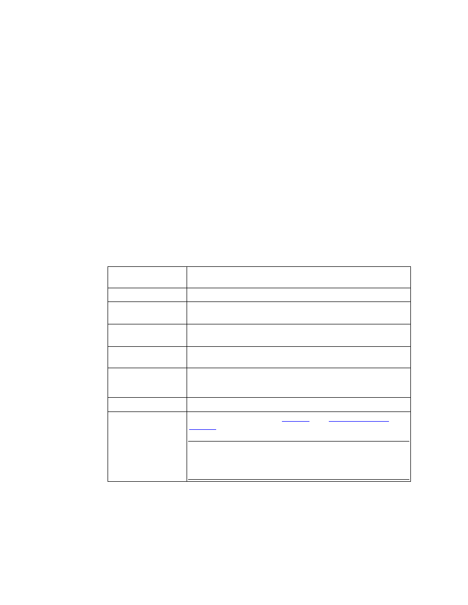
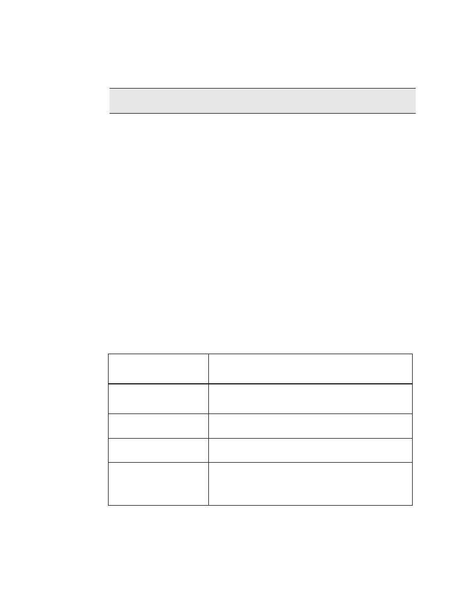
Retaining User Settings When Upgrading
As you use the program, many of your settings and other customizations are saved
as files in an application data folder. These settings, which remain constant
regardless of which project is open, include:
Application settings
These program-wide settings include startup preferences, default
file locations, and display properties. Application settings are
primarily found in the Options dialog.
Custom Import and Export
Format Definitions
These include changes to how file formats are defined in the
Import Format Editor and
Export Format Editor.
Project Templates
These include project settings, coordinate systems, view filters,
selection sets, and data that you have saved as project templates.
Internet Download
Configurations
These include new data provider groups and Internet sites that
you have added to the Internet Download command.
Baseline Processing and
Network Adjustment Styles
These include combinations of project settings that you have
defined as templates for baseline processing and network
adjustment.
When you upgrade from your current version of the program to a newer version,
the installation program searches for previous files containing these settings and
customizations. If any are found, the
Copy Settings
dialog appears.

Release Notes
18
To retain previous settings and c ustomizations:
1. In the
Copy
column, uncheck the box for each old file that you do not want to
retain in the upgrade.
2. Check the box for each old file that you do want to use to overwrite the new
file.
3. Click
Copy Selected Files
. The previous settings and customizations that you
selected are copied to the new installation.
Note: Any files that conflict with the files in the new installation are marked with
a red flag and are not selected by default.
Note: It is always a good idea to confirm your project and application settings in
the new installation to make sure that any new options in the current version are
set to the defaults you want.
Note: Customized menus and toolbars cannot be saved when you upgrade.
Document Outline
- Corporate Office
- Copyright and Trademarks
- Product Overview
- Languages
- New in Version 2.70
- Ease-of-use Features
- Performance-related Features
- Data Exchange-related Features
- Point-related Features
- Line-related Features
- Surface-related Features
- Corridor-related Features
- Drafting-related Features
- Image-related Features
- Data Prep-related Features
- Site Takeoff-related Features
- Site Mass Haul-related Features
- Corridor Mass Haul-related Features
- Field Data-related Features
- Survey-related Features
- Documentation
- Miscellaneous Features
- Enhancements from the BC-HCE 2.61 and 2.62 Patches
- Notes from the 2.60 Read Me File
- System Requirements
- Installation
- Notable Licensing Conditions
- Installing Licensed Modules
- Related Utilities
- Registration
- Retaining User Settings When Upgrading
Wyszukiwarka
Podobne podstrony:
DWL G700AP v2 31 release notes
GDD Release Notes v2 0 1 10
F 04 08 Release Notes
P2 53 5 Release Notes ISTA P ENG
F 02 02 Release Notes
SK6211 090411 Release Notes
191 07 Win7 Desktop Release Notes
185 85 WinXP GeForce Release Notes
F 02 11 Release Notes
videocapture release notes DVI7MFSN26EW6G2L7YD2U6M35ZLWDV3TQXDXQII
vegasvideo release notes WSFB47OPARMFHILPMPIR37S3HSPX53U3EJNQK4I
F 04 08 Release Notes
P2 53 5 Release Notes ISTA P ENG
Release Notes PC SDK 5 13
release notes 2 0 6 ru
Release Notes RobotWare Machining FC GUI v5 13
Red Hat Enterprise Linux 5 5 4 Release Notes en US
Red Hat Enterprise Linux 6 6 0 Release Notes en US
Red Hat Enterprise Linux OpenStack Platform 2 Release Notes en US
więcej podobnych podstron