INSTRUMENT PANEL
INDICATORS AND
SENDERS
H8.00-12.00XM (H170-280HD) [F007];
H13.00-16.00XM (H300-360HD) [E019];
H10.00-12.00XM-12EC (H360HD-EC) [E019]
PART NO. 1494143
2200 SRM 939

SAFETY PRECAUTIONS
MAINTENANCE AND REPAIR
• When lifting parts or assemblies, make sure all slings, chains, or cables are correctly
fastened, and that the load being lifted is balanced. Make sure the crane, cables, and
chains have the capacity to support the weight of the load.
• Do not lift heavy parts by hand, use a lifting mechanism.
• Wear safety glasses.
• DISCONNECT THE BATTERY CONNECTOR before doing any maintenance or repair
on electric lift trucks. Disconnect the battery ground cable on internal combustion lift
trucks.
• Always use correct blocks to prevent the unit from rolling or falling. See HOW TO PUT
THE LIFT TRUCK ON BLOCKS in the Operating Manual or the Periodic Mainte-
nance section.
• Keep the unit clean and the working area clean and orderly.
• Use the correct tools for the job.
• Keep the tools clean and in good condition.
• Always use HYSTER APPROVED parts when making repairs. Replacement parts
must meet or exceed the specifications of the original equipment manufacturer.
• Make sure all nuts, bolts, snap rings, and other fastening devices are removed before
using force to remove parts.
• Always fasten a DO NOT OPERATE tag to the controls of the unit when making repairs,
or if the unit needs repairs.
• Be sure to follow the WARNING and CAUTION notes in the instructions.
• Gasoline, Liquid Petroleum Gas (LPG), Compressed Natural Gas (CNG), and Diesel fuel
are flammable. Be sure to follow the necessary safety precautions when handling these
fuels and when working on these fuel systems.
• Batteries generate flammable gas when they are being charged. Keep fire and sparks
away from the area. Make sure the area is well ventilated.
NOTE: The following symbols and words indicate safety information in this
manual:
WARNING
Indicates a condition that can cause immediate death or injury!
CAUTION
Indicates a condition that can cause property damage!

Instrument Panel Indicators and Senders
Table of Contents
TABLE OF CONTENTS
General ...............................................................................................................................................................
Description .........................................................................................................................................................
General ...........................................................................................................................................................
Instrument Panel Meters, Indicators, and LCD Display ............................................................................
Error Code Display, Transmission ................................................................................................................
Error Code Display, Engine...........................................................................................................................
Connector .......................................................................................................................................................
Seat Switch Logic ......................................................................................................................................
Central Warning Light Output.................................................................................................................
Buzzer Output ...........................................................................................................................................
Engine Shutdown Output .........................................................................................................................
Instrument Panel Component Replacement ....................................................................................................
Instrument Panel...........................................................................................................................................
Remove.......................................................................................................................................................
Light ...............................................................................................................................................................
Replace .......................................................................................................................................................
Sender Replacement ..........................................................................................................................................
Fuel Level Sender ..........................................................................................................................................
Transmission Pressure and Temperature Sender, Tier 1 ............................................................................
Pressure Sender, Tier 2 .................................................................................................................................
Temperature Sender, Tier 2 ..........................................................................................................................
Low Coolant Sender.......................................................................................................................................
Vacuum Switch ..............................................................................................................................................
Crankshaft Position Sensor ..........................................................................................................................
Specifications......................................................................................................................................................
Troubleshooting..................................................................................................................................................
This section is for the following models:
H8.00-12.00XM (H170-280HD) [F007];
H13.00-16.00XM (H300-360HD) [E019];
H10.00-12.00XM-12EC (H360HD-EC) [E019]
©2004 HYSTER COMPANY
i

"THE
QUALITY
KEEPERS"
HYSTER
APPROVED
PARTS
2200 SRM 939
Description
General
Meters provide information to the operator on the
condition of various systems. Gauges may be either
direct reading (mechanical) or indirect (electrical).
Unlike mechanical gauges, electrical gauges have
electrical meter movements, light emitting diodes
(LEDs), or digital displays inside the case. These me-
ters receive an electrical signal from a sender unit,
usually in the engine or transmission case.
This
section only describes electrical meters, senders, and
instrument panel displays.
Meters and displays are used to provide operator
information on the status of many systems, includ-
ing engine oil pressure, fuel level, transmission oil
pressure, engine coolant temperature, transmission
oil temperature, and hour display, and transmission
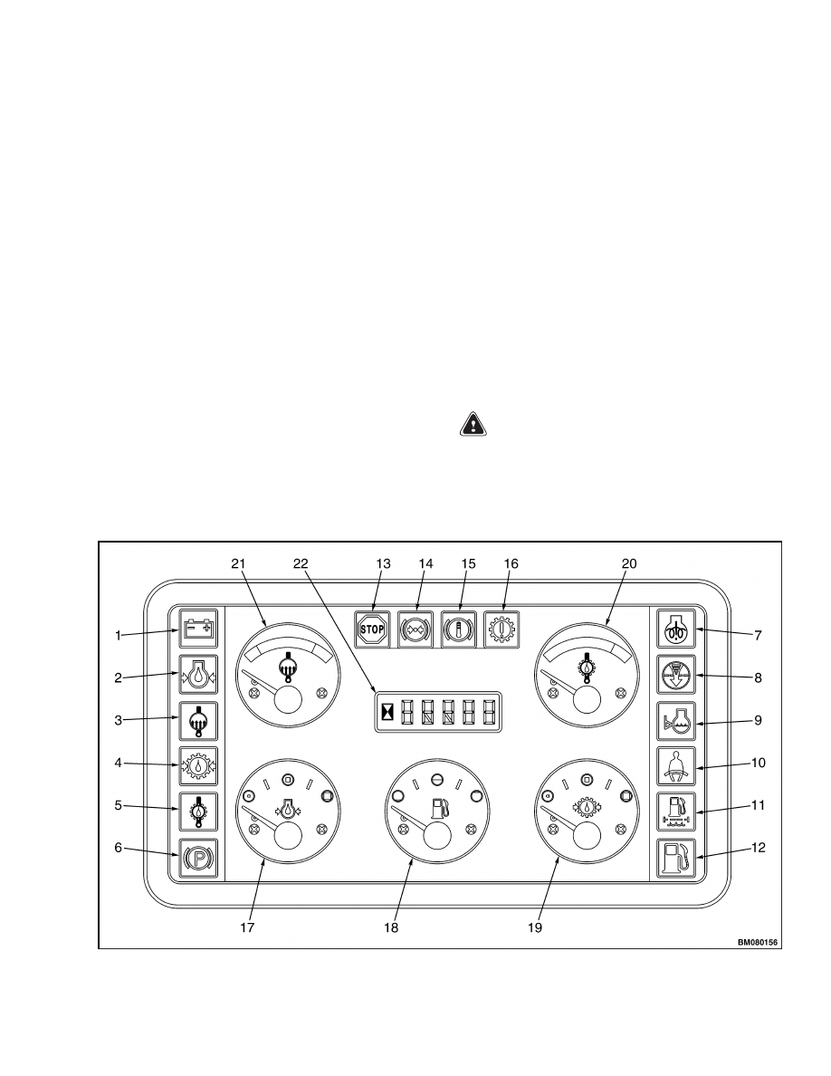
fault codes. For further data, see Figure 1.
Description
GENERAL
Many meters have meter movements that move an
indicating needle attached to a shaft (or pin). The
shaft rotates to swing the needle. Shaft rotation of a
meter is limited to less than one full revolution. Me-
ter faces are calibrated to indicate a range of values.
For examples of meter faces and indicators, see Fig-
ure 1.
Many meters and displays require a separate sender.
INSTRUMENT PANEL METERS,
INDICATORS, AND LCD DISPLAY
WARNING
If any of the instruments do not operate as de-
scribed in the following tables, DO NOT oper-
ate lift truck until problem is corrected.
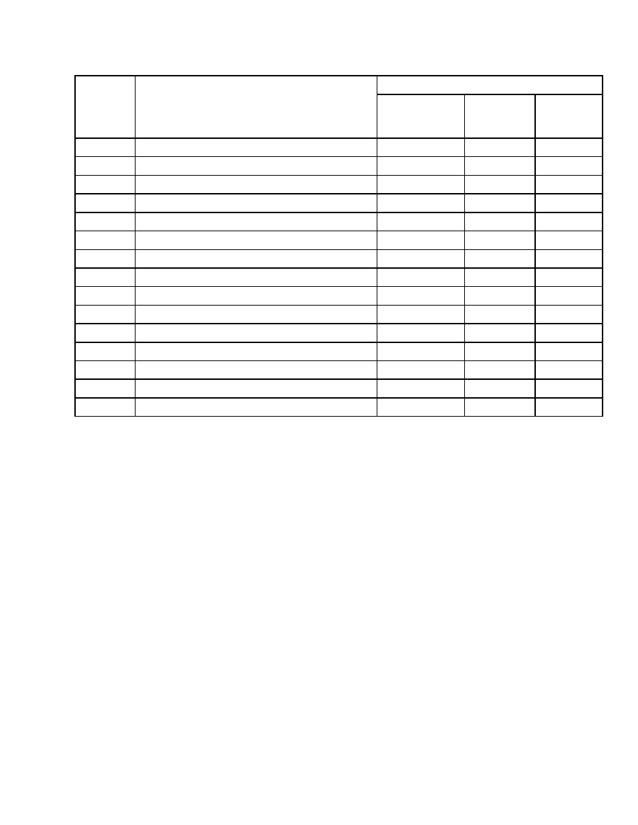
Figure 1. Instrument Panel and Indicators
1
Description
2200 SRM 939
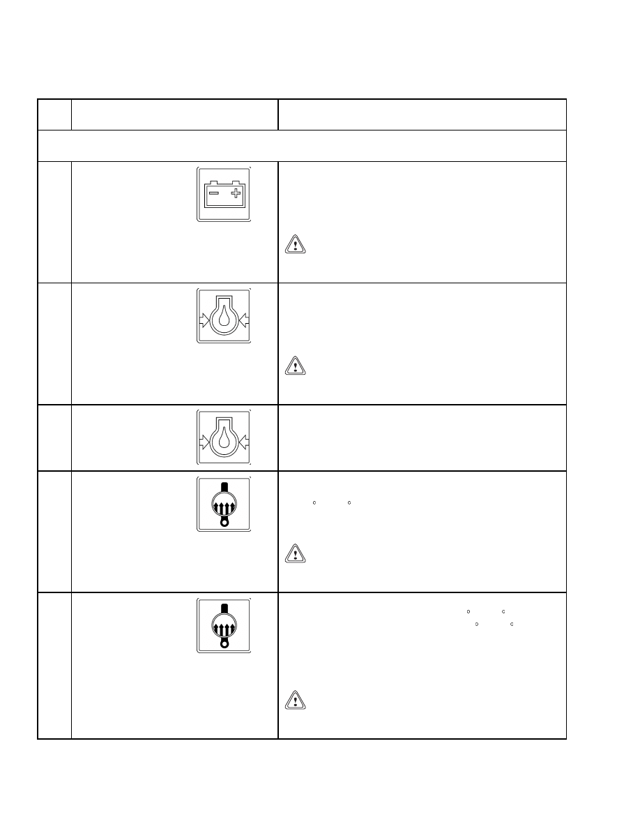
Table 1. Instrument Panel and Indicators
Item
No.
Item
Function
NOTE: For all warning lights, except the battery warning light and the cold start warning
light, there is a light check after power-up.
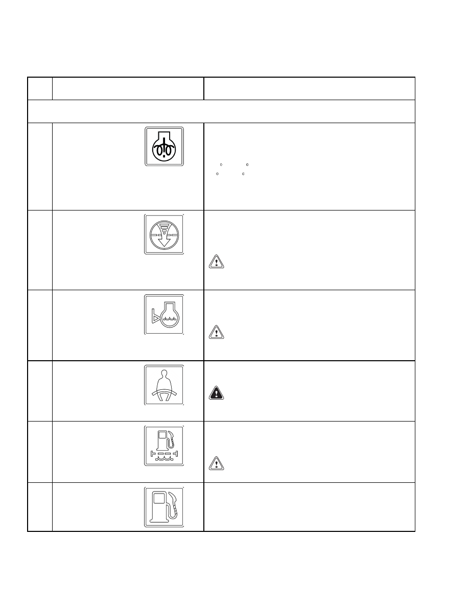
1
Battery Charging
Condition Warning
Light
The light will NOT come ON when the key is placed in
the ON position and the engine is not running. The light
must be OFF while the engine is running. If the light
comes ON during operation, there is a problem that must
be checked immediately.
CAUTION
Do not continue to operate the lift truck if the red
light is ON at engine speeds above idle.
2
Low Engine Oil
Pressure Warning
Light, Tier 1
The red light must be OFF when the engine is running.
If the engine oil pressure is less than or equal to 69 kPa
(10 psi), the red light will come ON, and a buzzer will
sound. The central warning light will also come ON, and
30 seconds later, the engine will shut down.
CAUTION
Stop the engine immediately if the red light is ON
while the engine is running.
2
Low Engine Oil
Pressure Warning
Light, Tier 2
The red light must be OFF, when the engine is
running. When the engine oil pressure gets below
200 kPa (29 psi)above 950 rpm, or gets below 150 kPa
(22 psi)below 950 rpm, the red light will be ON.
3
Coolant Temperature
Warning Light, Tier 1
The red light must be OFF when the engine is running.
If the engine coolant temperature is more than or equal
to 120 C (248 F), the red light will come ON, and a buzzer
will sound. The central warning light will also come ON,
and 30 seconds later, the engine will shut down.
CAUTION
Do not continue to operate the lift truck when the
light is ON. This indicates that the engine is too hot.
3
Coolant/Intake Air
Temperature Warning
Light, Tier 2
The red light must be OFF when the engine is running.
If the engine cooling is more than 110 C (230 F), or the
intake air temperature is more than 76 C (169 F), the
red light will come ON, and a buzzer will sound. The
central warning light will also come ON and the start
aid/diagnostic/engine warning light will flash. The engine
may be de-rated.
CAUTION
Do not continue to operate the lift truck when the
light is ON. This indicates that the engine is too hot.
2
2200 SRM 939
Description
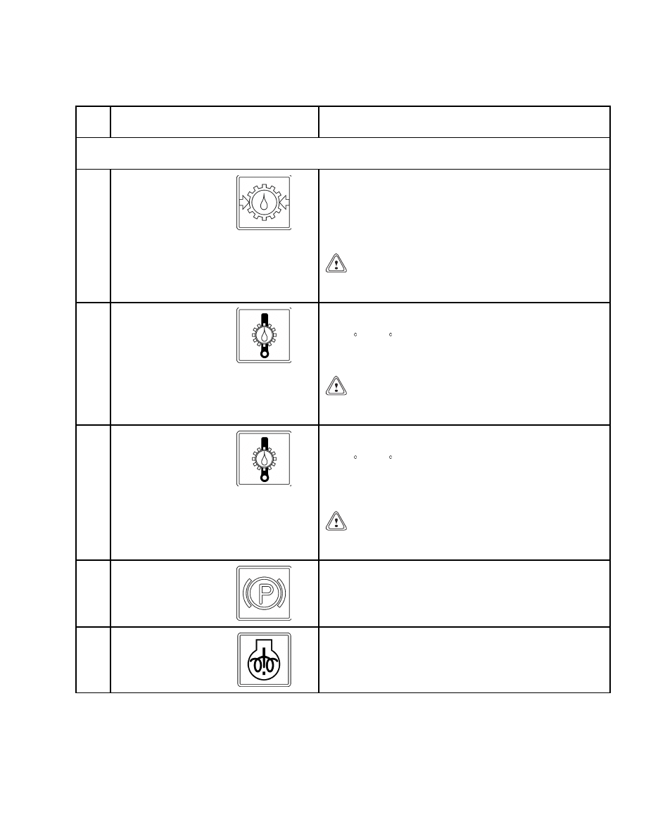
Table 1. Instrument Panel and Indicators (Continued)
Item
No.
Item
Function
NOTE: For all warning lights, except the battery warning light and the cold start warning
light, there is a light check after power-up.
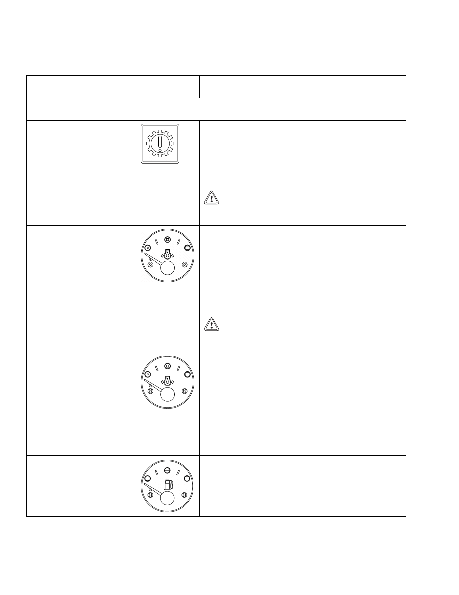
4
Transmission Oil
Pressure Warning
Light
The red light is ON when the key switch is in the START
position and must go OFF when the engine is running.
If the transmission oil pressure is less than or equal to
1000 kPa (145 psi), the red light will come ON, and a
buzzer will sound. The central warning light will also
come ON.
CAUTION
Do not continue to operate the lift truck if the red
light is ON.
5
Transmission Oil
Temperature Warning
Light, Tier 1
The red light must be OFF when the engine is running.
If the transmission oil temperature is more than or equal
to 132 C (270 F), the red light will come ON, and a buzzer
will sound. The central warning light will also come ON,
and 30 seconds later, the engine will shut down.
CAUTION
Do not continue to operate the lift truck if the red
light is ON.
5
Transmission Oil
Temperature Warning
Light, Tier 2
The red light must be OFF when the engine is running.
If the transmission oil temperature is more than or equal
to 132 C (270 F), the red light will come ON, and a buzzer
will sound. The central warning light will also come ON,
the stop engine warning light will flash and, the engine
may be derated.
CAUTION
Do not continue to operate the lift truck if the red
light is ON.
6
Park Brake Warning
Light
The light is ON when the park brake is applied or when
there is not enough pressure to release the parking brake.
7
Cold Start Warning
Light, Tier 1
The cold start warning light is ON when the cold start
button (Perkins Engine Only) is depressed to aid in
starting the engine.
3
Description
2200 SRM 939
Table 1. Instrument Panel and Indicators (Continued)
Item
No.
Item
Function
NOTE: For all warning lights, except the battery warning light and the cold start warning
light, there is a light check after power-up.
7
Start Aid/Diagnostic/
Engine Warning
Light, Tier 2
The start aid/diagnostic/engine warning light is ON
before the engine is cranked and the cold start aid
is activated. The start aid/diagnostic/engine warning
light flashes when the coolant temperature is over
110 C (230 F), or the intake air temperature is over
76 C (169 F). The engine may be derated. If the start
aid/diagnostic/engine warning light is ON when the
engine is running, or has been shut down, an electrical
fault has been detected.
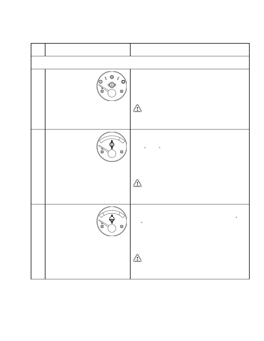
8
Engine Air Filter
Warning Light
The red light must be OFF when the engine is running.
The engine air filter warning light is ON when the engine
air filter is dirty or has an obstruction. If the light is ON,
replace the air filter element.
CAUTION
Do not operate the lift truck when the light is ON.
Stop the truck immediately.
9
Coolant Level
Warning Light
The red light must be OFF when the engine is running.
If the engine coolant is low, the red light will come on.
The central warning light will also come on.
CAUTION
Do not continue to operate the lift truck when the
light is ON. This indicates that the engine is too hot.
10
Seat Belt Warning
Light
This orange light is ON for 10 seconds after the key is
placed in the ON position.
WARNING
Before driving the lift truck, always fasten your
safety belt.
11
Fuel Filter Warning
Light
The orange light must be OFF when the engine is
running. The orange fuel filter warning light is ON when
the fuel filter is dirty or has an obstruction.
CAUTION
Clean or replace the fuel filter immediately.
12
Fuel Reserve Warning
Light
The orange light must be OFF when the engine is
running. The orange fuel reserve warning light is ON
when the fuel level is below 10% of the fuel tank capacity.
The central warning light will also come ON.
4

2200 SRM 939
Description
Table 1. Instrument Panel and Indicators (Continued)
Item
No.
Item
Function
NOTE: For all warning lights, except the battery warning light and the cold start warning
light, there is a light check after power-up.
13
STOP Engine Warning
Light, Tier 1
The red light must be OFF when the engine is running.
When either the engine coolant temperature, the
transmission oil temperature, or the engine oil pressure
reaches the alarm values, the STOP light, the central
light, and buzzer will be activated. After 30 seconds, the
truck will automatically shut down. This can be reset by
turning the key switch to OFF and back ON, which will
allow the driver 30 seconds to move the truck.
CAUTION
When the light is ON, immediately STOP the lift
truck.
13
STOP Engine Warning
Light, Tier 2
The red light must be OFF when the engine is running.
When the transmission oil temperature gets above 132 C
(270 F) the STOP light flashes, the central light and
buzzer will be activated, and the engine may be derated.
When the engine oil pressure, above 950 rpm, gets below
200 kPa (29 psi) but above 150 kPa (22 psi) the STOP
light will be ON Below 150 kPa (22 psi) the STOP light
will Flash, the central light and buzzer will be activated,
and the engine may be derated. When the engine oil
pressure, below 950 rpm, gets below 150 kPa (22 psi), the
STOP light will flash, the central light and buzzer will be
activated, and the engine may be derated.
14
Low Brake Pressure
Warning Light
The red light must be OFF when the engine is running.
The red light is ON when the pressure in the brake
system is too low. The central warning light will also
come ON.
WARNING
Do not operate the lift truck when the light is ON.
15
High Brake
Temperature Warning
Light
The red light must be OFF when the engine is running.
This red light is ON when the temperature in the brake
system is higher than normal operating temperature for
brake system. The central warning light will also come
on.
WARNING
Do not operate the lift truck when the light is ON.
5
Description
2200 SRM 939
Table 1. Instrument Panel and Indicators (Continued)
Item
No.
Item
Function
NOTE: For all warning lights, except the battery warning light and the cold start warning
light, there is a light check after power-up.
16
Transmission Failure
Warning Light
The red light must be OFF when the engine is running.
This red light comes ON (solid or flashes) when a
transmission error occurs. At the same time, an error
code is displayed in the hourmeter display. The central
warning light will also come ON, when the red light is
ON (solid). Sometimes a buzzer will sound. For further
reference see Error Code Display, Transmission.
CAUTION
Do not continue to operate the lift truck if the red
light is ON.
17
Engine Oil Pressure
Gauge, Tier 1
Gauge indicates normal engine oil pressure when the
needle is approximately in the middle of the scale. If the
engine oil pressure drops to less than or equal to 69 kPa
(10 psi), the red light will come ON and a buzzer will
sound. The central warning light will also come ON, and
30 seconds later, the engine will shut down. The engine
shutdown can be reset by turning the key switch to OFF
and back ON, which will allow the driver 30 seconds to
move the truck.
CAUTION
Stop the engine immediately if the red light is ON
while the engine is running.
17
Engine Oil Pressure
Gauge, Tier 2
When the engine is running the gauge indicates normal
engine oil pressure when the needle is approximately in
the middle of the scale. When the engine oil pressure,
above 950 rpm, gets below 200 kPa (29 psi) but above
150 kPa (22 psi) the STOP light will be ON. Below
150 kPa (22 psi) the STOP light will flash, the central
light and buzzer will be activated, and the engine may be
derated. When the engine oil pressure, below 950 rpm,
gets below 150 kPa (22 psi), the STOP light will flash,
the central light and buzzer will be activated, and the
engine may be derated.
18
Fuel Level Gauge
This gauge indicates the level of fuel in the fuel tank.
When the fuel level is 10% or less of the tank capacity,
the orange warning light will come ON and the central
warning light also will come ON.
6
2200 SRM 939
Description
Table 1. Instrument Panel and Indicators (Continued)
Item
No.
Item
Function
NOTE: For all warning lights, except the battery warning light and the cold start warning
light, there is a light check after power-up.
19
Transmission Oil
Pressure Gauge
Gauge indicates the transmission oil pressure while the
engine is running. During normal operation, the gauge
needle is approximately in the middle of the scale. If
the pressure drops to 1000 kPa (145 psi) or less, the red
warning light will come ON, the buzzer will sound, and
the central warning light will come ON.
CAUTION
Do not continue to operate the lift truck when the
gauge indicates that the transmission oil pressure
is too low.
20
Transmission Oil
Temperature Gauge
Gauge indicates the transmission oil temperature while
the engine is running. During normal operation, the
gauge needle will be in the green zone. If the temperature
is 132 C (270 F) or greater, the red warning light will
come ON, the buzzer will sound, the central warning light
will come ON, and the engine will shut down 30 seconds
later. The engine shutdown can be reset by turning the
key switch to OFF and back ON, which will allow the
driver 30 seconds to move the truck.
CAUTION
Do not continue to operate the lift truck when the
gauge indicates that the transmission oil tempera-
ture is too high (needle in the red zone).
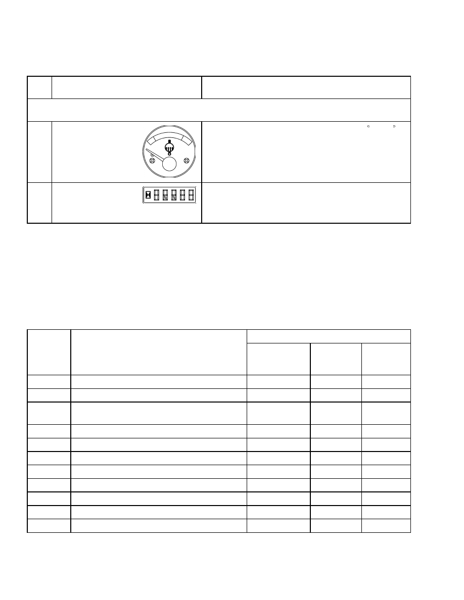
21
Coolant Temperature
Gauge, Tier 1
Gauge indicates engine coolant temperature when key
switch is ON. During normal operation, the gauge needle
will be in the green zone. If the temperature is 120 C
(248 F) or greater, the red warning light will come ON,
the buzzer will sound, the central warning light will come
ON, and the engine will shut down 30 seconds later. The
engine shutdown can be reset by turning the key switch
to OFF and back ON, which will allow the driver 30
seconds to move the truck.
CAUTION
Do not continue to operate the lift truck when the
gauge indicates that the engine is too hot (needle in
the red zone).
7
Description
2200 SRM 939
Table 1. Instrument Panel and Indicators (Continued)
Item
No.
Item
Function
NOTE: For all warning lights, except the battery warning light and the cold start warning
light, there is a light check after power-up.
21
Coolant Temperature
Gauge, Tier 2
When the coolant Temperature gets above 110 C (230 F),
the start aid/diagnostic/engine warning light flashes,
red warning light will be ON, the buzzer will sound, the
central warning light will come ON, and the engine will
be derated.
22
Hourmeter and Error
Code Indicator
The hourmeter operates while the engine is running.
Periodic Maintenance recommendations are based on
these hours. It also displays transmission error codes to
alert the driver of any problems with the transmission.
ERROR CODE DISPLAY, TRANSMISSION
Transmission system error codes take precedence
over hourmeter and will display error codes listed
below as required. If multiple errors occur simul-
taneously, error codes will continually scroll every
3 seconds until error condition is resolved. When
multiple errors exist, truck functionality responds
to worst case error condition. Transmission system
exceeded parameters (error codes 1 through 6) are
self-correcting error conditions and will return truck
to normal functionality when parameter require-
ments are satisfied. Error codes 30 through 41 occur
when equipment failure creates a condition that
could lead to possible safety issues and/or equip-
ment damage and requires component repair or
replacement and a system reset to resume normal
truck functionality. Normal hourmeter display will
return when error conditions are corrected and truck
functionality restored.
Display Output
Error
Code
Description
Transmission
Warning
Light
Central
Warning
Light
Buzzer
ERR01
Reversal speed exceeded
Flash
ERR02
Downshift speed exceeded
Flash
ERR03
High engine. rpm. Prevents transmission
engage
Flash
ERR04
Open
Flash
ERR05
Lift height exceeded (factory setting)
Solid
Solid
ERR06
Lift height exceeded
Solid
Solid
ON
ERR07
Controller communication failure
Flash
ERR08
Transmission speed sensor-downshift inhibit
Flash
ERR09
Open
Flash
ERR10
Open
Flash
ERR11
Open
Solid
8
2200 SRM 939
Description
Display Output
Error
Code
Description
Transmission
Warning
Light
Central
Warning
Light
Buzzer
ERR12
Open
Flash
ON
ERR30
Transmission low oil pressure
Solid
Solid
ON
ERR31
Transmission high oil temperature
Solid
Solid
ERR32
Transmission speed sensor
Solid
Solid
ERR33
Engine speed sensor
Solid
Solid
ERR34
Throttle position switch
Solid
Solid
ERR35
Forward solenoid
Solid
Solid
ERR36
Reverse solenoid
Solid
Solid
ERR37
First gear solenoid
Solid
Solid
ERR38
Second gear solenoid
Solid
Solid
ERR39
Fwd/Rev selected at the same time
Solid
Solid
ERR40
Multiple range shifter positions
Solid
Solid
ERR41
Transmission controller failure
Solid
Solid
ERR42
Open
Solid
Solid
ON
ERR43
Open
Solid
Solid
ON
ERROR CODE DISPLAY, ENGINE
The start aid/diagnostic/engine warning light can
be used to identify a diagnostic code. The code will
identify the component, but cannot identify the fault
within the component.
After the code has been
flashed there will be a delay of five seconds before
the next code is flashed. The sequence of flashing
may be restarted at any time by reactivating the
cycling of the key switch.
To identify the fault codes, proceed as follows:
NOTE: The start aid/diagnostic/engine warning light
will flash in a sequence that will identify the diag-
nostic code. For example, flash code 517 will be five
flashes, a delay, one flash, a delay, and seven flashes.
Each flash will be 0.5 seconds long and the delay be-
tween flashes is 0.3 seconds. The delay between each
digit of the code will be 2 seconds. See Table 2 for
identification of fault codes.
For more in-depth fault finding, use diagnostic code
reader (hand held service tool).
1.
Cycle the key switch OFFand ON twice within 3
seconds.
2.
Wait for 2 seconds.
3.
Count the number of flashes and write down the
code.
NOTE: Future changes to the diagnostic software are
as follows:
• The stop engine warning light will flash once to
indicate the start of the active fault codes.
• The start aid/diagnostic/engine warning light will
flash repeatedly indicating the active fault codes in
the same manner as current.
• If there are no active fault codes, then the start
aid/diagnostic/engine warning light will give code
111. If there is more than one active code, the stop
engine warning light will flash once to indicate the
end of one code and the start of another.
9

Description
2200 SRM 939
• After all of the active fault codes have flashed, the
stop engine warning light will flash twice to indi-
cate the start of logged fault codes. The flash se-
quence of logged codes is the same for that of active
codes. Once all the logged fault codes have flashed,
the start aid/diagnostic/engine warning light will
flash three times. Cycling the key switch twice
within three seconds will start the process again.
• All fault codes will flash in chronological order,
rather than numerical order.
Table 2. Engine Error Code Descriptions
CID Number
Description
Flash Code
0041
8 volt power supply
517
0091
Throttle position sensor
154
0100
Engine oil pressure sensor
157
0102
Intake manifold pressure sensor
135
0105
Intake manifold air temperature
sensor
133
0110
Engine coolant temperature
sensor
168
0174
Fuel temperature sensor
165
0247
J1939 data link
514
0253
Personality module
416
0262
5 volt power supply
516
0320
Engine speed/Timing sensor
141
0342
Secondary engine speed sensor
142
0774
Secondary throttle position sensor
155
1684
Fuel injection pump
158
1743
Mode selector switch for engine
operation
144
1894
Cruise control status switch
427
1895
Toggle switch for cruise control
speed
428
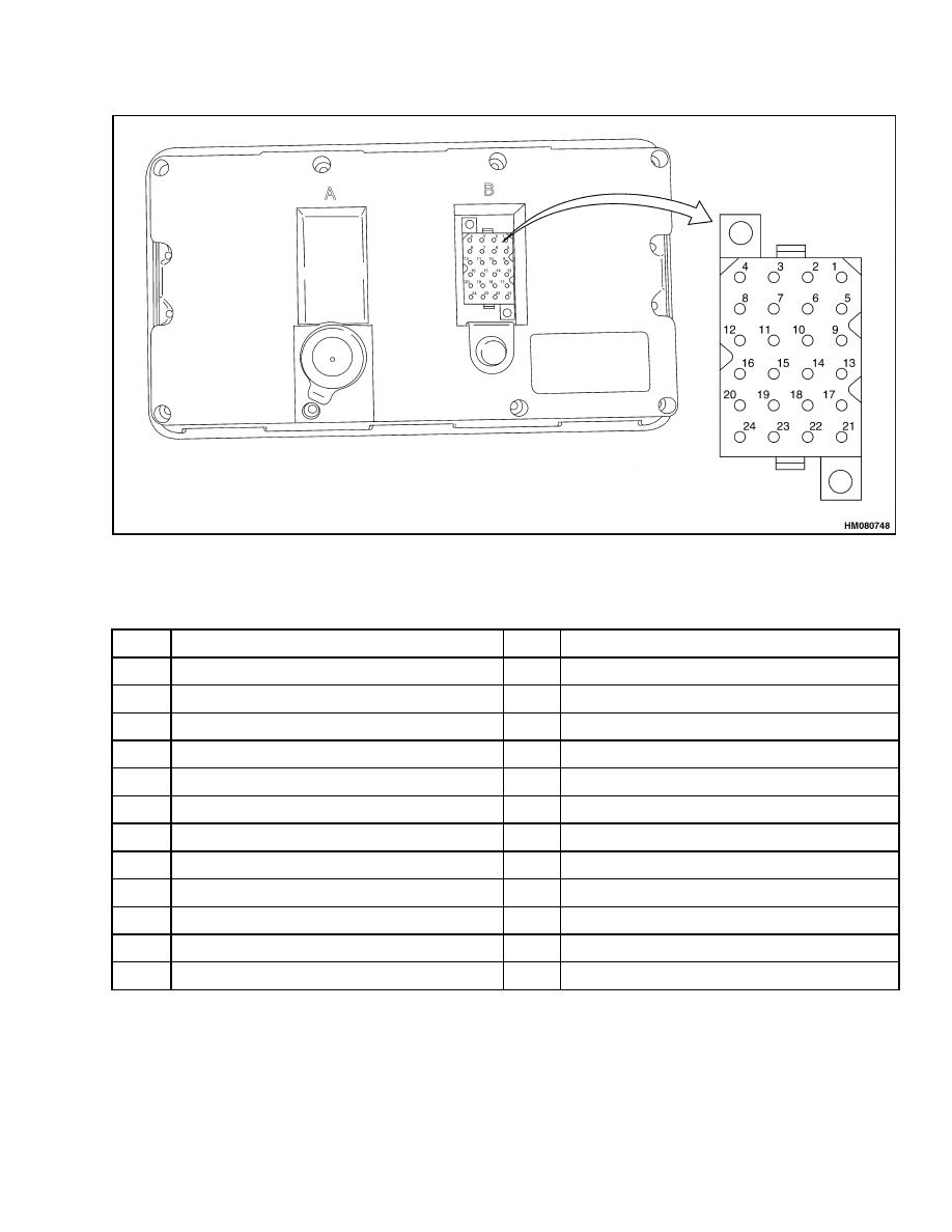
CONNECTOR
Instrument panel is connected to the system by
means of one connector. Connector is located at rear
of instrument panel. See Figure 2 and Table 3.
Seat Switch Logic
This function warns the operator when leaving the
seat without applying park brake. Two and one-half
seconds after having detected this condition, buzzer
is activated and stays ON for 10 seconds.
The seat switch is connected to pin number 2. When
seat is occupied, pin number 2 is connected to ground.
When seat is not occupied, input to pin number 2 is
open.
10
2200 SRM 939
Description
Figure 2. Connector
Table 3. Pin Description
Pin
Description
Pin
Description
1
Battery positive input
13
Brake system pressure light input
2
Seat switch input
14
RS-232 Receive input
3
Battery charging light input
15
RS-232 Transmission output
4
Ground
16
RS-232 Ground
5
Engine coolant level light input
17
Buzzer output
6
Brake system temperature light input
18
Shutdown output
7
Park brake monitor input
19
Central light output
8
Start aid/Engine warning light input
20
Engine coolant temperature gauge input
9
Engine combustion air filter input
21
Engine oil pressure gauge input
10
Fuel filter light input
22
Transmission oil pressure gauge input
11
Neutral gear input
23
Transmission oil temperature gauge input
12
Stop engine light input, Tier 2 only
24
Fuel level gauge input
11
Description
2200 SRM 939
Central Warning Light Output
This output is at pin number 19 and switches to
ground when any of the following conditions occur:
• Engine oil pressure is too low
• Engine coolant temperature is too high
• Transmission oil pressure is below 999 kPa
(145 psi)
• Transmission oil temperature is above 132 C
(269 F)
• Fuel level is below 10% of the capacity
• Brake system pressure warning light is ON
• Brake system temperature warning light is ON
• Engine coolant level warning light is ON
• Transmission errors activating the central warn-
ing light (refer to error code display in the LCD)
• Intake manifold air temperature is high
Buzzer Output
This output is at pin number 17 and switches to
ground when any of the following conditions occur:
• Low engine oil pressure
• High engine coolant temperature
• Transmission oil pressure is below 1000 kPa
(145 psi)
• Transmission oil temperature is above 132 C
(270 F)
• Transmission errors activating the buzzer (refer to
error code display in the LCD)
• When the operator is not present and park brake is
not applied, the buzzer will sound for 10 seconds.
• High intake manifold air temperature
Engine Shutdown Output
NOTE: For Tier 2 engines, light 13 flashes.
This output is at pin number 18 and switches to
ground after a shutdown condition occurs.
When
either the engine coolant temperature (Tier 1),
transmission oil temperature, or engine oil pressure
reaches the alarm values, light 13 and the central
warning light will turn ON, and the buzzer will
sound, indicating shutdown condition.
Shutdown
output switches to ground and after a delay, the
engine is stopped.
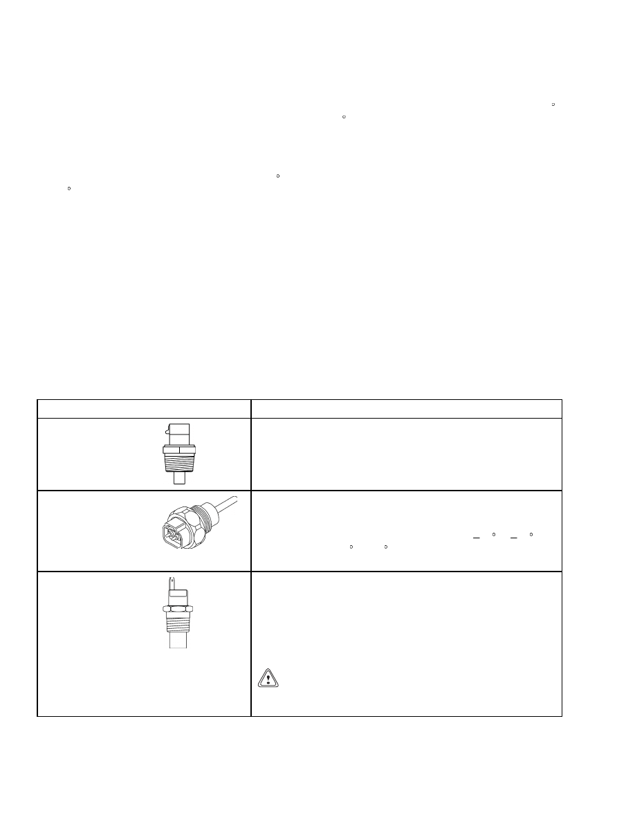
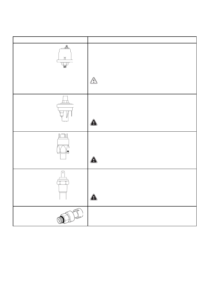
Table 4. Sender Description
Item
Function
Water Temperature
Sender, Tier 1
The water temperature sender is mounted in the engine block
and senses the water temperature. If the water temperature
exceeds the specified temperature, the sender sends a signal to
the control panel and lights the coolant temperature indicator.
This signal also drives the coolant temperature gauge.
Water Temperature
Sender, Tier 2
The water temperature sender used with a Tier 2 engine is a
thermistor type sensor with an output between 0 and 5 volts.
The ECM will detect a fault condition, if the voltage from the
sensor is not within the range of 0.2 volts at
40 C ( 40 F)
and 4.9 volts at 150 C (302 F), and the fault is present for more
than 8 seconds continuously.
Transmission Oil
Temperature Sender
The transmission oil temperature sender unit is mounted
in the transmission oil sump and senses the transmission
fluid temperature. When the transmission temperature
exceeds system specifications, the sender sends a signal to the
instrument panel and lights the transmission oil temperature
warning light. This signal also drives the transmission oil
temperature gauge.
CAUTION
Do not continue to operate the lift truck when the gauge
indication is in the red area of the gauge.
12
2200 SRM 939
Description
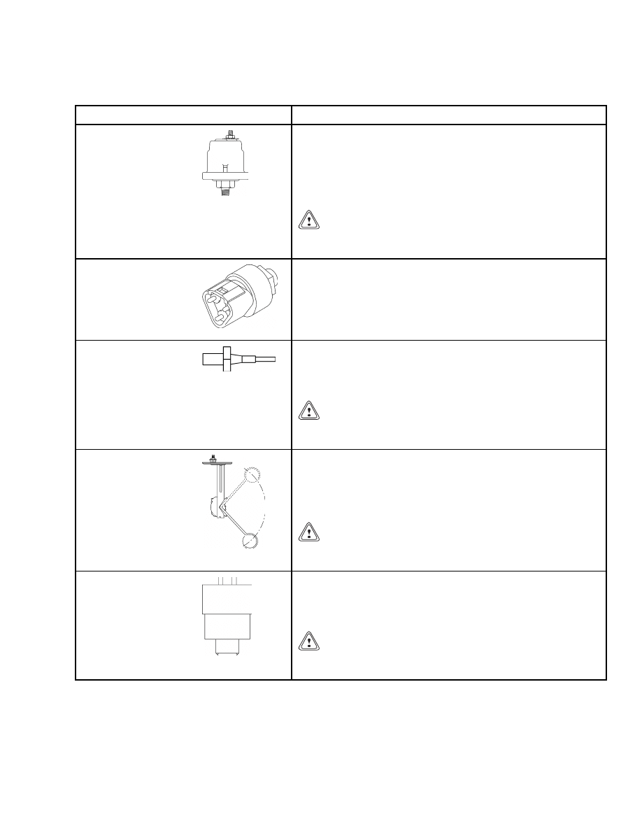
Table 4. Sender Description (Continued)
Item
Function
Engine Oil Pressure
Sender, Tier 1
The engine oil pressure sender is located on the side of the
engine block and senses the engine oil pressure. If the oil
pressure drops lower than specifications, the sender sends a
signal to the control panel and lights the engine oil pressure
indicator. The engine oil pressure sender signal also drives
the engine oil pressure gauge.
CAUTION
Do not continue to operate the lift truck at engine speeds
above idle if the red light is ON.
Engine Oil Pressure
Sender, Tier 2
The engine oil temperature sender used with a Tier 2 engine
is a active sensor with an output between 0 and 5 volts. The
ECM will detect a fault condition, if the voltage from the
sensor is not within the range of 0.5 volts representing 106 kPa
(15 psi)and 4.5 volts representing 795 kPa (115 psi), and the
fault is present for more than 8 seconds continuously
Low Coolant Sender
The low coolant sender is mounted in the coolant system
radiator near the top of the tank. It senses the fluid level and,
when low, sends a signal to the control panel and lights the
coolant system fluid low warning indicator.
CAUTION
Do not continue to operate the lift truck if the orange
light is ON during operation.
Fuel Level Sender
The fuel level sender is installed in the fuel tank and indicates
when the fuel is low. An internal float sends a signal to the
control panel and lights the fuel level low warning indicator.
A signal is also sent to the fuel level gauge to indicate the
amount of fuel remaining in the tank.
CAUTION
Do not continue to operate the lift truck if the orange
light is ON during operation.
Vacuum Switch
The vacuum switch is mounted on the air filter housing (left
side of the truck). It senses the air intake pressure and sends
a signal to the instrument panel. It switches warning light 8
ON when the air intake pressure drops below 6.4 kPa (0.9 psi).
CAUTION
Lift truck performance will be limited when the red light
is ON.
13
Description
2200 SRM 939
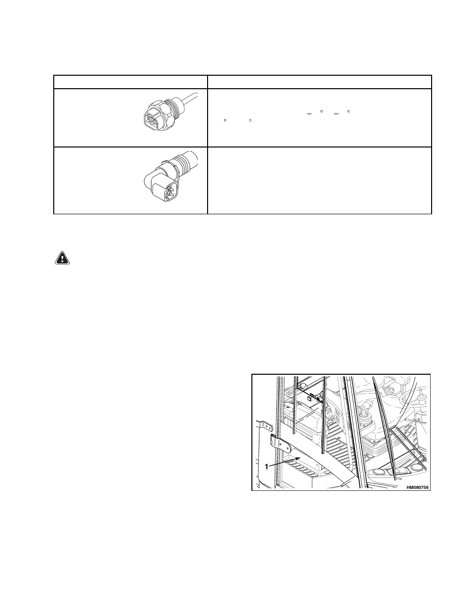
Table 4. Sender Description (Continued)
Item
Function
Transmission Oil
Pressure Sender
The transmission oil pressure sender unit is mounted in the
transmission on the engine side and senses the transmission
fluid pressure. When the transmission oil pressure drops below
specifications, the sender sends a signal to the instrument
panel and lights the transmission oil pressure warning light
4. The transmission oil pressure sender also drives the
transmission oil pressure gauge.
CAUTION
Do not continue to operate the lift truck when the red
light is ON at engine speeds above idle.
Low Pressure Sender
(Air Brakes Only)
The low pressure sender is mounted in the manifold on the
cab tilt frame and senses the brake system pressure. When
pressure drops below specified value, the sender sends a signal
to the instrument panel and lights the low pressure warning
light 14.
WARNING
Never operate a truck with a brake malfunction.
Low Pressure Sender
(Wet Brakes Only)
The low pressure sender is mounted in the manifold on the
cab tilt frame and senses the brake system pressure. When
pressure drops below specified value, the sender sends a signal
to the instrument panel and lights the low pressure warning
light 14.
WARNING
Never operate a truck with a brake malfunction.
Brake Temperature
Sender (Wet Brakes
Only)
The brake temperature senders are mounted in the wheel
hubs (one on the left-side and one on the right-side hub) and
sense the brake fluid temperature. If the fluid temperature
exceeds high temperature specifications, the senders send a
signal to the instrument panel and lights warning light 15.
WARNING
Never operate a truck with a brake malfunction.
Intake Manifold
Pressure Sensor, Tier 2
This is an active sensor with and output between 0 and 5 volts.
The ECM will recognize the output to be valid if it is between
0.5 volts representing 52 kPa (8 psi) and 4.5 volts representing
306 kPa (44 psi).
14
2200 SRM 939
Instrument Panel Component Replacement
Table 4. Sender Description (Continued)
Item
Function
Intake Manifold
Temperature Sensor,
Tier 2
This is a thermistor type sensor with an output between 0
and 5 volts. The ECM will recognize the output to be valid
if it is between 0.2 volts at
40 C ( 40 F) and 4.9 volts at
150 C (302 F). Sensor diagnostics will detect a fault if the
input voltage is outside this range for more than 2 seconds
continuously.
Crankshaft Position
Sensor, Tier 2
This is a magnetic type sensor that measures both crankshaft
speed and position. The sensor will measure speeds above
246 rpm when the output will be greater than 0.4 volts peak
to peak. The sensor detects the passing of teeth on a wheel.
These teeth are spaced at 1/36 intervals of the wheel. One
tooth is missing to facilitate the position measurement. There
are a total of 36 teeth.
Instrument Panel Component Replacement
WARNING
Before replacing any components, fully lower
all parts of the mast and tilt it forward until the
tips of the forks touch the ground. This action
will prevent the mast from lowering suddenly
if the control lever is accidently moved.
ALWAYS disconnect the battery and remove op-
erator key before replacing components.
Never have any metal on your fingers, arms, or
neck. These metal items can accidentally make
an electrical connection and may cause an in-
jury.
Meters, display panels, most indicators, and senders
are not repairable items. The most accurate and usu-
ally easiest check for proper operation of individual
meters, indicators, or senders is direct replacement.
The most common cause of failure is poor connections
or damaged or improper wiring, and not the meter
indicator or sender. This section only has the re-
placement procedures. Before a meter, display panel,
indicator, or sender is replaced, make the following
checks.
1.
Check that other meters and electrical circuits
operate correctly.
2.
Check that the battery is fully charged and has a
good ground, and cable terminals are clean and
tight.
3.
Check that the wiring and connections to meter,
indicator, or sender are tight and in good condi-
tion.
INSTRUMENT PANEL
Remove
NOTE: The only replaceable parts of the instrument
panel are the lights.
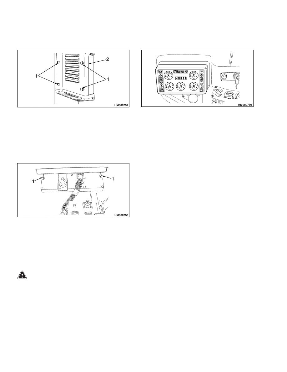
1.
Locate the fuse panel. See Figure 3.
2.
Disconnect ground lead of battery.
1.
FUSE PANEL
Figure 3. Fuse Panel Location
15
Sender Replacement
2200 SRM 939
3.
Loosen four retaining screws and remove the fuse
panel cover. See Figure 4.
1.
RETAINING SCREWS
2.
FUSE PANEL COVER
Figure 4. Fuse Panel Screws
4.
From the fuse panel side, using a flat blade
screwdriver, depress clips holding instrument
panel in place. Left side first, then right side.
See Figure 5.
1.
PANEL CLIPS
Figure 5. Fuse Panel Clips
5.
Pull instrument panel away from the console.
See Figure 6.
Figure 6. Instrument Panel Removal
6.
Disconnect plug from socket.
7.
Loosen 12 screws at rear of instrument panel.
8.
Remove rear cover from instrument panel.
LIGHT
Replace
1.
Turn light holder counterclockwise and remove.
2.
Insert replacement light holder.
3.
Turn replacement light holder clockwise and
tighten.
4.
Mount cover.
Sender Replacement
FUEL LEVEL SENDER
WARNING
Before replacing any components, fully lower
all parts of the mast and tilt it forward until the
tips of the forks touch the ground. This action
will prevent the mast from lowering suddenly
if the control lever is accidently moved.
ALWAYS disconnect the battery and remove op-
erator key before replacing components.
Never have any metal on your fingers, arms, or
neck. These metal items can accidentally make
an electrical connection and may cause an in-
jury.
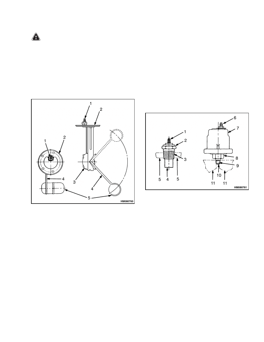
The fuel level sending unit is mounted to fuel tank
surface (usually top surface) with screws through
the sender plate and gasket. See Figure 7. Correct
sender operation and screw hole alignment can only
be obtained with plate mounted in one position.
Replace sender as follows:
16
2200 SRM 939
Sender Replacement
WARNING
All fuel vapors are extremely explosive. Do not
have sparks or flames around vehicles or fuel
storage and service areas. Make sure there is
no source of open flame or sparks in the vicin-
ity. Use caution to prevent sparks from tools.
1.
Turn key switch to OFF position. Disconnect
battery positive cable at battery. Install a lock
or tag on connector to prevent connection.
2.
Disconnect sender wire at sender.
1.
ELECTRICAL
TERMINAL
2.
PLATE
3.
SENDER UNIT
4.
FLOAT ARM
5.
FLOAT
Figure 7. Fuel Level Sender
3.
Remove screws that fasten sender plate to tank.
4.
Remove sender.
5.
Carefully install new sender. Use a new gasket.
6.
Verify screw holes are aligned and install screws.
Tighten screws enough to partially compress gas-
ket to prevent leaks.
7.
Remove tape from wire connector and install con-
nector on sender terminal.
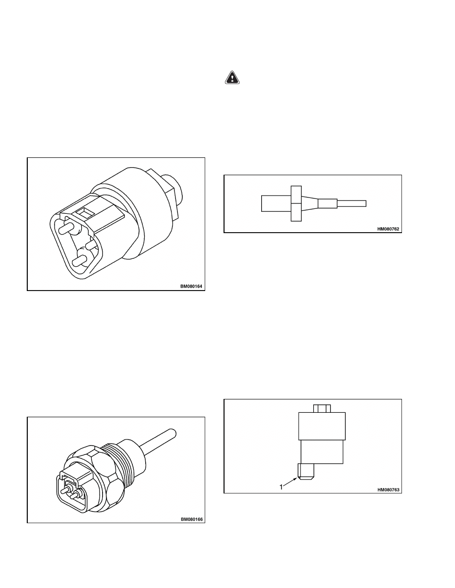
TRANSMISSION PRESSURE AND
TEMPERATURE SENDER, TIER 1
Some pressure senders have a hollow threaded fit-
ting fastened to the base. See Figure 8. This makes it
possible for sender to sense pressure and also to fas-
ten sender to the equipment. It is possible to tighten
or loosen sender using a wrench on flats of fitting.
The body of temperature sender has threads to fit a
threaded hole in the equipment. This sender also has
a hex shape for tightening or loosening sender. Re-
place senders as follows:
1.
ELECTRICAL TERMINAL
2.
SENDER
3.
THREADED BODY
4.
SENSOR ELEMENT
5.
CASE OF ENGINE OR TRANSMISSION
6.
ELECTRICAL TERMINAL
7.
SENDER
8.
HEX NUT
9.
THREADED FITTING
10. HOLE TO SENSOR ELEMENT
11. CASE OF ENGINE OR TRANSMISSION
Figure 8. Typical Pressure and Temperature
Senders
17
Sender Replacement
2200 SRM 939
PRESSURE SENDER, TIER 2
NOTE: If applicable, replace O-ring when replacing
sender.
1.
Turn key switch to OFF position.
2.
Disconnect electrical connector.
3.
Remove pressure sender. See Figure 9.
4.
Install new pressure sender.
Figure 9. Pressure Sender, Tier 2
TEMPERATURE SENDER, TIER 2
NOTE: If applicable, replace O-ring when replacing
sender.
1.
Turn key switch to OFF position.
2.
Disconnect electrical connector.
3.
Remove temperature sender. See Figure 10.
4.
Install new temperature sender.
Figure 10. Temperature Sender, Tier 2
LOW COOLANT SENDER
WARNING
High temperature risk. Radiator temperature
may be high and radiator may be pressurized.
NOTE: Verify system fluid is drained so that level
is below sender to prevent leakage when sender is
removed.
1.
Turn key switch to OFF position.
2.
Disconnect sender wire. See Figure 11.
Figure 11. Low Coolant Sender
3.
Turn sender counterclockwise and remove.
4.
Install a new sender.
Use Teflon tape.
Turn
clockwise and tighten. Torque 5.6 ±0.6 N•m (50
±5 lbf in).
5.
Connect sender wire.
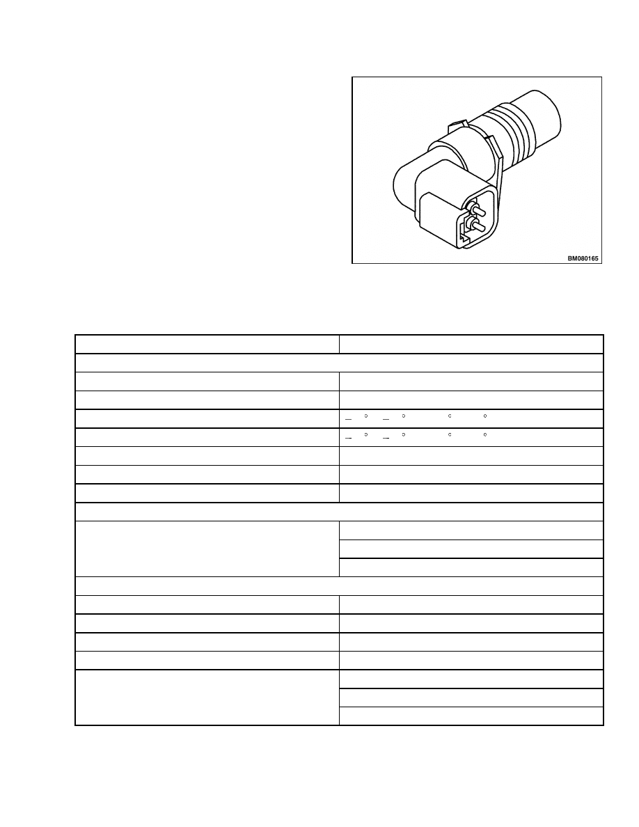
VACUUM SWITCH
1.
Turn key switch to OFF position.
2.
Disconnect amp connector. See Figure 12.
3.
Remove vacuum switch.
4.
Install a new vacuum switch.
1.
AMP CONNECTOR
Figure 12. Vacuum Switch
18
2200 SRM 939
Specifications
CRANKSHAFT POSITION SENSOR
NOTE: If applicable, replace O-ring when replacing
sensor.
1.
Turn key switch to OFF position.
2.
Disconnect electrical connector.
3.
Remove crankshaft position sensor.
See Fig-
ure 13.
4.
Install new crankshaft position sensor.
Figure 13. Crankshaft Position Sensor
Specifications
Item
Design Data
Instrument Panel
Supply voltage
22-32 Vdc
Nominal and test voltage
26 Vdc
Working temperature
25 C ( 13 F) to +65 C (149 F)
Storage temperature
40 C ( 40 F) to +80 C (176 F)
Transparent surface
Glass
Warning lights (except battery charging)
24 Vdc 1.2W
Warning light battery charging
24 Vdc 2W
Gauges
Actuator: coil type or PWM coil type
Needle stroke: 90 degrees
Instrument panel gauges
Reading tolerances: ±4 degrees
Hourmeter/Error LCD Display
View angle
12 o’clock
Polarized
Transflective. Positive
Drive method
1/2 Duty
Driving voltage
5.0 Vdc
Engine running hours
Maximum 99,999 hours
Indication
Error codes indication
19

Specifications
2200 SRM 939
Item
Design Data
Senders
Operating voltage
24 Vdc
Water temperature sender, Tier 1
Body threads
5/8-18 UNF-2A
Hex (across flats)
20 mm (0.787 in.)
Water temperature sender, Tier 2
Body threads
M18x1.5
Transmission oil temperature sender
Body threads
1/2-14 NPTF
Hex (across flats)
22 mm (0.866 in.)
Engine oil pressure sender, Tier 1
Body threads
1/8-27 NPTF
Hex (across flats)
17 mm (0.670 in.)
Engine oil pressure sender, Tier 2
Body threads
M12x1.5
Transmission oil pressure
Body threads
1/8-27 NPTF
Hex (across flats)
22 mm (0.866 in.)
Low coolant sender
Body threads
1/8-27 NPTF
Hex (across flats)
22 mm (0.866 in.)
Sender terminal threads
Fits connector type Delphi P/N 121521193
Fuel sender plate
Number of holes
5
Hole size
5.1 mm
Low pressure sender (air brakes only)
Body threads
1/8-27 NPTF
Hex (across flats)
11 mm (0.44 in.)
Low pressure sender (wet brakes only)
Body threads
1/4" NPT
Hex (across flats)
27 mm (1.062 in.)
Brake temperature sender (wet brakes only)
Body threads
3/8" NPTF
Vacuum switch
Body threads
1/8-27 NPTF
20

2200 SRM 939
Troubleshooting
Item
Design Data
Intake manifold pressure sensor
Body threads
M14x1.5
Intake manifold temperature sensor
Body threads
M18x1.5
Troubleshooting
PROBLEM
POSSIBLE CAUSE
PROCEDURE OR ACTION
No Indication - All Meters
Battery disconnected.
Clean the battery terminals and bat-
tery cable connectors. Install connec-
tors.
Battery malfunction or discharged.
Charge or replace battery.
Wiring group connector or connec-
tors not connected.
Fasten the connector or connectors.
No Indication - Only One
Meter
Meter wires damaged or not con-
nected.
Replace display connectors. Install
connectors on proper meter termi-
nals.
Separate sender wire damaged or
not connected.
Replace broken wire or connector. In-
stall connector on sender terminal.
Meter malfunction. Voltage is at ter-
minal.
Replace fault display.
Sender malfunction. No voltage is at
terminal.
Replace sender.
Incorrect Indication
Battery is discharged.
Charge battery.
Meter movement or needle is dam-
aged or has a malfunction.
Replace fault display.
Separate sender malfunction.
Replace sender.
Sender will not sense because sys-
tem has corrosion.
Clean and flush system. Check for
bent or cracked sensor tubing.
21

NOTES
____________________________________________________________
____________________________________________________________
____________________________________________________________
____________________________________________________________
____________________________________________________________
____________________________________________________________
____________________________________________________________
____________________________________________________________
____________________________________________________________
____________________________________________________________
____________________________________________________________
____________________________________________________________
____________________________________________________________
____________________________________________________________
____________________________________________________________
____________________________________________________________
____________________________________________________________
____________________________________________________________
____________________________________________________________
____________________________________________________________
22


TECHNICAL PUBLICATIONS
2200 SRM 939
12/04 (7/03)(2/03)(11/00) Printed in United Kingdom
Document Outline
- toc
- tables
Wyszukiwarka
Podobne podstrony:
1538373 2200SRM1065 (02 2004) UK EN
1559550 2200SRM1097 (10 2004) UK EN
Alternator 2200SRM0002 (12 2004) US EN
1494141 1800SRM0937 (12 2003) UK EN
1519772 2200SRM1016 (10 2004) UK EN
897495 2200SRM0514 (01 2004) UK EN
910110 2200SRM0143 (08 2004) UK EN
1564268 2200SRM1106 (01 2004) UK EN
1578950 2200SRM1119 (08 2004) UK EN
1565183 2200SRM1110 (08 2004) UK EN
897928 2200SRM0625 (12 1996) UK EN
910442 8000SRM0231 (12 2004) UK EN
1556871 2200SRM1105 (01 2004) UK EN
więcej podobnych podstron