ALTERNATOR WITH
REGULATOR
COVERS DELCO, MOTOROLA, AND
LEECE-NEVILLE ALTERNATORS USED
ON HYSTER LIFT TRUCKS
PART NO. 899784
2200 SRM 2

SAFETY PRECAUTIONS
MAINTENANCE AND REPAIR
• When lifting parts or assemblies, make sure all slings, chains, or cables are correctly
fastened, and that the load being lifted is balanced. Make sure the crane, cables, and
chains have the capacity to support the weight of the load.
• Do not lift heavy parts by hand, use a lifting mechanism.
• Wear safety glasses.
• DISCONNECT THE BATTERY CONNECTOR before doing any maintenance or repair
on electric lift trucks.
• Disconnect the battery ground cable on internal combustion lift trucks.
• Always use correct blocks to prevent the unit from rolling or falling. See HOW TO PUT
THE LIFT TRUCK ON BLOCKS in the Operating Manual or the Periodic Mainte-
nance section.
• Keep the unit clean and the working area clean and orderly.
• Use the correct tools for the job.
• Keep the tools clean and in good condition.
• Always use HYSTER APPROVED parts when making repairs. Replacement parts
must meet or exceed the specifications of the original equipment manufacturer.
• Make sure all nuts, bolts, snap rings, and other fastening devices are removed before
using force to remove parts.
• Always fasten a DO NOT OPERATE tag to the controls of the unit when making repairs,
or if the unit needs repairs.
• Be sure to follow the WARNING and CAUTION notes in the instructions.
• Gasoline, Liquid Petroleum Gas (LPG), Compressed Natural Gas (CNG), and Diesel fuel
are flammable. Be sure to follow the necessary safety precautions when handling these
fuels and when working on these fuel systems.
• Batteries generate flammable gas when they are being charged. Keep fire and sparks
away from the area. Make sure the area is well ventilated.
NOTE: The following symbols and words indicate safety information in this
manual:
WARNING
Indicates a condition that can cause immediate death or injury!
CAUTION
Indicates a condition that can cause property damage!

Alternator with Regulator
Table of Contents
TABLE OF CONTENTS
General ...............................................................................................................................................................
Description .........................................................................................................................................................
Alternator Repair...............................................................................................................................................
Alternator Type A ..........................................................................................................................................
Remove and Disassemble..........................................................................................................................
Clean ..........................................................................................................................................................
Assemble ....................................................................................................................................................
Install .........................................................................................................................................................
Alternator Type B ..........................................................................................................................................
Remove and Disassemble..........................................................................................................................
Clean ..........................................................................................................................................................
Assemble ....................................................................................................................................................
Install .........................................................................................................................................................
General Check and Adjustment ........................................................................................................................
Low Output Check (Type A or Type B) .............................................................................................................
High Output Check (Type A or Type B) ............................................................................................................
Brushes Circuit Check.......................................................................................................................................
Delco Alternators ...........................................................................................................................................
Motorola Alternators .....................................................................................................................................
Diodes Check ......................................................................................................................................................
Diode Bridge Check ...........................................................................................................................................
Delco and Leece-Neville Alternators ............................................................................................................
Motorola Alternators .....................................................................................................................................
Rotor Field Winding Check ...............................................................................................................................
Stator Windings Check ......................................................................................................................................
Voltage Regulator Check ...................................................................................................................................
Troubleshooting..................................................................................................................................................
This section is for the following models:
Covers Delco, Motorola, and Leece-Neville alternators used
on Hyster lift trucks
©2004 HYSTER COMPANY
i

"THE
QUALITY
KEEPERS"
HYSTER
APPROVED
PARTS
2200 SRM 2
Description
General
CAUTION
When using an arc welder, always disconnect
the ground lead from the lift truck battery to
prevent alternator or battery damage. Attach
the welding ground clamp as close to the weld
area as possible to prevent welding current
from damaging the bearings.
The diodes and resistors in the electrical sys-
tem can be damaged if the following cautions
are not followed:
• Do not disconnect the battery when the en-
gine is running. The voltage surge can dam-
age the diodes and resistors in the electrical
system.
• Do not disconnect an electric wire before the
engine is stopped and the switches are OFF.
• Do not cause a short circuit by connecting the
electric wires to the wrong terminals. Make
sure a correct identification is made of the
wire before it is connected.
• Make sure a battery is the correct voltage and
polarity before it is connected.
• Do not check for current flow by making a
spark because the electronic components can
be damaged.
NOTE: Information on alternators manufactured
outside the United States is in the SRM (Service
Repair Manual) sections for lift trucks that use those
alternators.
This section has a description and the repair proce-
dures for the alternator with a voltage regulator as
part of the alternator.
Description
NOTE: For this SRM section, the alternators are in
two groups: Type A and Type B. The two types are
very similar, but the Type A alternators have a set of
three diodes (diode set) as well as the diode bridge.
The Type B alternator has zener diodes as part of
the diodes in the diode bridge. This alternator does
not have a diode set, but does have an additional fan
inside the rear housing. The basic operation of both
types is very similar.
The alternator generates an alternating current
when the engine is running. The alternator is either
ON or OFF. The alternator generates maximum
current when it is ON and no current when it is
OFF. The regulator switches the alternator between
ON and OFF to get the average current needed
to charge the battery. Alternator output is directly
changed by engine speed and rotor field current. The
alternating current is changed to a direct current by
the diode bridge inside the alternator.
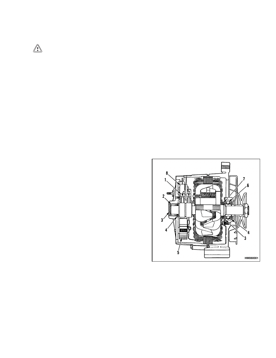
The alternator has these parts (see Figure 1 and Fig-
ure 2):
A stator
A rotor
A diode bridge
A diode set (Type A only)
Two end housings or frame halves
A solid-state voltage regulator
NOTE: DELCO TYPE A SHOWN.
1.
BRUSH ASSEMBLY
2.
ROLLER BEARING
3.
GREASE
RESERVOIR
4.
LIP SEAL
5.
DIODE BRIDGE
6.
BALL BEARINGS
7.
FELT SEAL
8.
REGULATOR
Figure 1. Alternator Cross Section
1
Description
2200 SRM 2
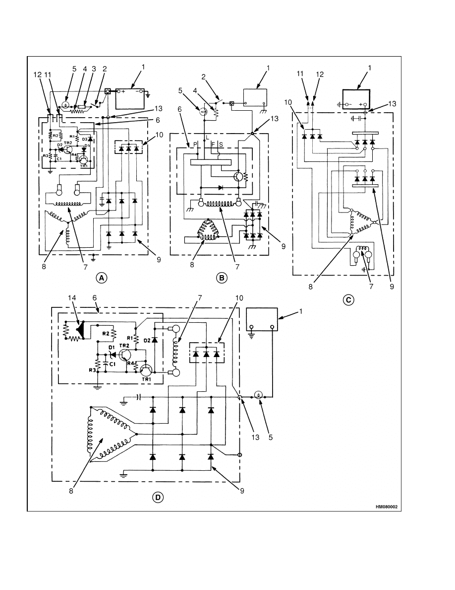
Figure 2. Alternator Schematics
2

2200 SRM 2
Alternator Repair
Legend for Figure 2
NOTE: LEECE-NEVILLE NOT AVAILABLE, SIMILAR TO THOSE SHOWN.
A. DELCO TYPE A (SMALL CAPACITY LIFT
TRUCKS)
B. DELCO TYPE B
C. MOTOROLA TYPE A
D. DELCO TYPE A (LARGE CAPACITY LIFT
TRUCKS)
1.
BATTERY
2.
KEY SWITCH
3.
FUSE
4.
RESISTOR
5.
INDICATOR LIGHT OR AMMETER
6.
VOLTAGE REGULATOR
7.
ROTOR FIELD
8.
STATOR
9.
DIODE BRIDGE
10. DIODE SET
11. FIELD TERMINAL
12. REGULATOR TERMINAL
13. OUTPUT (BAT) TERMINAL
14. VOLTAGE ADJUSTMENT
The direct current from the diodes of the diode bridge
flows to the output or BAT terminal. A capacitor be-
tween the BAT terminal and the electrical ground re-
moves any remaining alternating current from the
direct current. The capacitor also protects the diodes
from high voltages. The voltage is controlled by the
amount of current flowing through the field winding
in the alternator and the rpm of the rotor. The volt-
age regulator, inside the housing, contains a transis-
tor, diodes, resistors, and capacitor. The voltage reg-
ulator cannot be repaired.
NOTE: On some large capacity lift trucks, the alter-
nator has an external voltage adjustment.
The voltage regulator controls the alternator to
charge the battery. The voltage is set by the man-
ufacturer and is not usually adjustable.
Battery
voltage decreases as the starting circuit and other
circuits take energy from the battery.
When the
key switch is put in the IGN position, the voltage
regulator is energized. A positive current flows to
the field terminal (F or 1) on Type A alternators
and (L) on Type B alternators. The battery sends a
positive current to the regulator terminal (Type A R
or 2) and the BAT terminal. The regulator senses a
decrease in battery voltage and increases the alter-
nator output to charge the battery.
Alternator Repair
ALTERNATOR TYPE A
Remove and Disassemble
WARNING
Always disconnect the battery ground cable be-
fore making repairs to prevent possible dam-
age and injury. Install a tag on the battery ter-
minal so that no one connects the cable on the
terminal.
NOTE: Use Troubleshooting and General Check and
Adjustment, Low Output Check (Type A or Type B),
High Output Check (Type A or Type B), Brushes Cir-
cuit Check, Diodes Check, Diode Bridge Check, Rotor
Field Winding Check, Stator Windings Check, and
Voltage Regulator Check procedures of this SRM be-
fore starting any repair procedures. Make sure that
repair or replacement of that part is necessary before
removal, disassembly, or replacement of the part.
NOTE: There are some checks of the alternator that
are done with the alternator on the engine.
See
General Check and Adjustment, Low Output Check
(Type A or Type B), High Output Check (Type A
or Type B), Brushes Circuit Check, Diodes Check,
Diode Bridge Check, Rotor Field Winding Check,
Stator Windings Check, and Voltage Regulator
Check procedures of this SRM before starting any
removal or repair procedures.
NOTE: Many parts of the Leece-Neville alternator
can be replaced without disassembling the alterna-
tor. See Figure 5. The alternator must be disassem-
bled to replace only the diode bridge, filter capacitor,
rotor, stator, or bearings.
1.
Disconnect the battery ground cable. See Fig-
ure 3, Figure 4, and Figure 5. Install labels and
disconnect the wires at the alternator. Loosen
the alternator mount capscrews and remove the
drive belt. Remove the capscrews that hold the
alternator to the engine.
3
Alternator Repair
2200 SRM 2
2.
On
Leece-Neville
alternators,
remove
the
brushes, voltage regulator, or diode set.
In-
stall labels on all wires for correct connection
during installation.
3.
Put a mark on each housing and on the stator for
correct alignment during assembly. Remove the
bolts that hold the housings together. Separate
the housings and stator.
4.
Put the rotor in a vise that has soft jaws. Do not
tighten the vise to cause rotor distortion. Use a
socket wrench to remove the pulley nut. Remove
the pulley, fan, collar, spacer, shield, or other
parts between the fan and housing. Remove the
front housing from the rotor.
5.
Remove any nuts or screws that fasten parts in-
side to the rear housing. Then, remove the sta-
tor assembly from the rear housing so that the
other parts can be removed. Remove the screws
for the capacitor, diode bridge, diode set, brushes,
and other parts as necessary. If the stator will
be removed from the diode bridge, make sure the
wires have tags for correct connection during as-
sembly.
6.
Mark the stator to show the position of the
brushes and connector or diode bridge assembly.
Use pliers as a heat sink to keep heat from the
diodes. Use a soldering iron to remove the stator
leads from the diode assembly.
7.
Remove the bearings from the housings only if
they will be replaced.
Clean
WARNING
Compressed air can move particles so that they
cause injury to the user or to other personnel.
Make sure that the path of the compressed air
is away from all personnel.
Wear protective
goggles or a face shield to prevent injury to the
eyes.
CAUTION
Never use solvent on the parts of the alternator.
NOTE: If necessary, use fine abrasive cloth to polish
the slip rings. The abrasive cloth must be number
500 to 600. Remove all dust. Turn the rotor while
polishing the slip rings.
Use compressed air to remove dirt from the alterna-
tor. Clean the brushes and slip rings with a clean,
dry cloth.
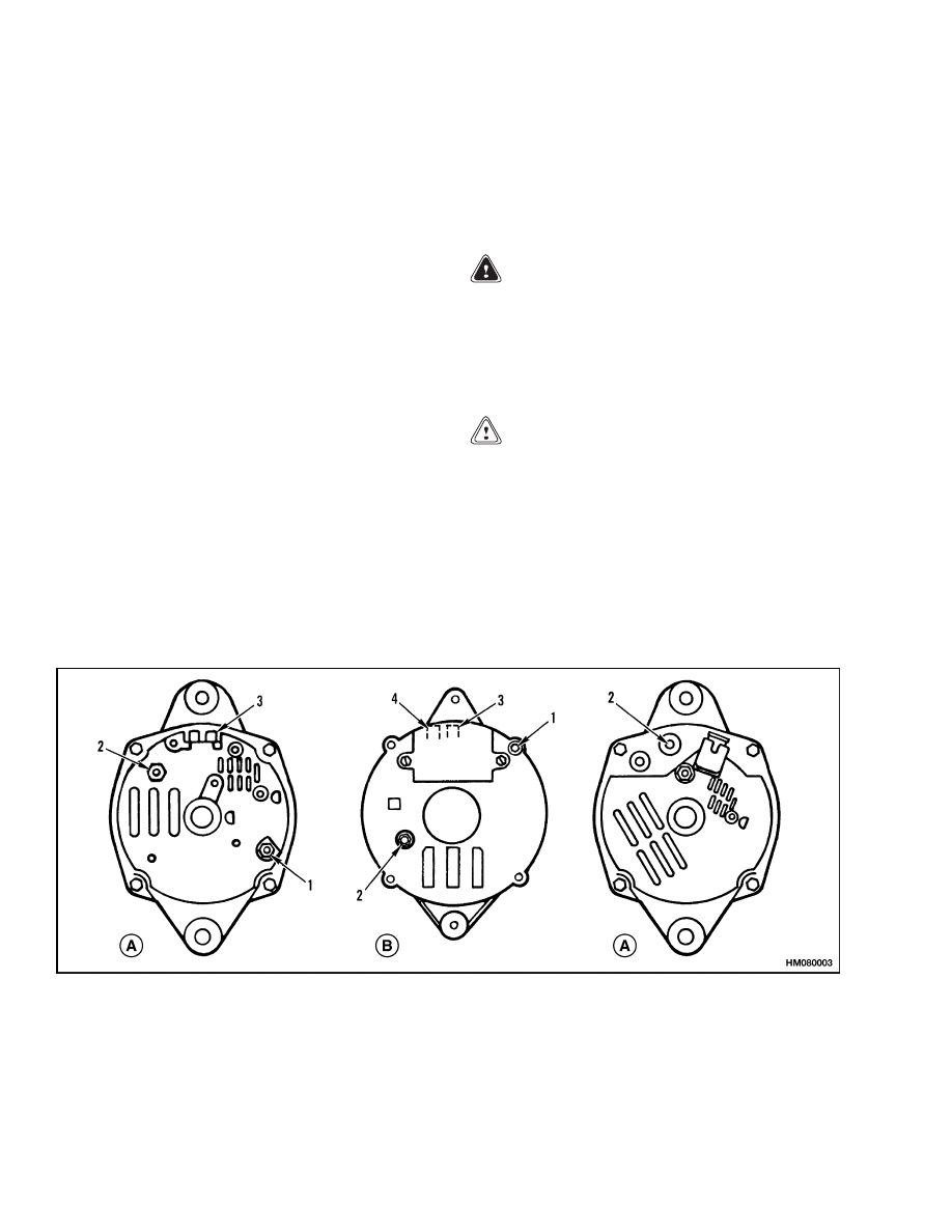
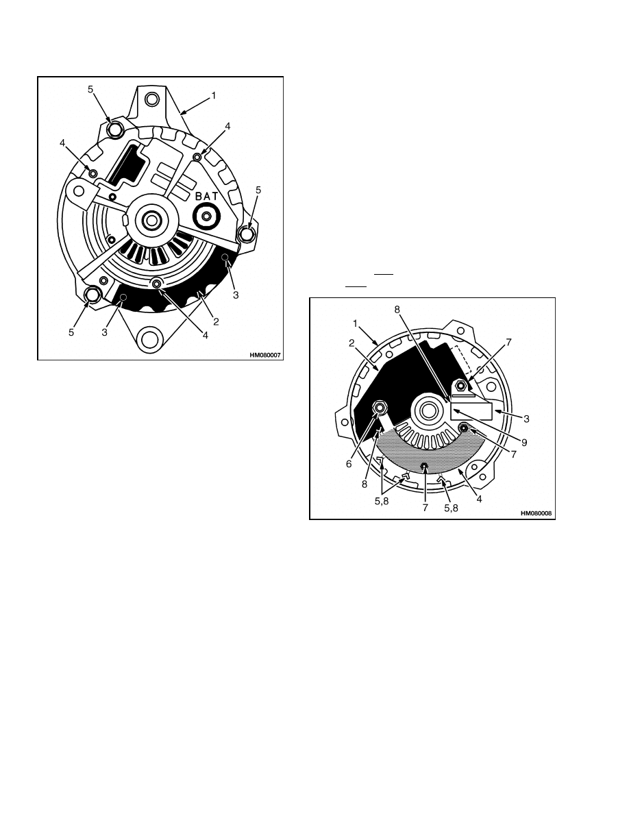
A. DELCO
B. MOTOROLA
1.
GROUND TERMINAL
2.
BATTERY TERMINAL (BAT OR +)
3.
FIELD TERMINAL
4.
REGULATOR TERMINAL
Figure 3. Type A Alternators, Rear Views
4

2200 SRM 2
Alternator Repair
Assemble
1.
For Delco (Type A) alternators, install a new
bearing(s) in the housing as follows (see Fig-
ure 3, Figure 4, and Figure 5):
a. Install a new plug and seal in the rear hous-
ing. Push the bearing from the outside of the
housing until the top of the bearing is even
with the outside of the housing. Hold the
housing with the collar on the inside of the
housing. Keep the lip of the seal away from
the bearing. Lubricate the bearing area with
non-conductive grease.
b. Install a new bearing in the front housing.
Fill one quarter of the grease reservoir with
non-conductive grease. Move the grease so
that it touches the bearing when the retainer
plate is installed.
c.
Add the same type of grease to fill the area
between the retainer plate and the bearing.
Install the spacer, gasket, and retainer plate
on the bearing. Fasten the retainer plate in
position with the three screws and lockwash-
ers.
2.
For Motorola and Leece-Neville alternators, use
a press to install the rear bearing on the rotor.
Install the bearing and bearing retainer in the
front housing. If used, install the spacer on the
bearing.
CAUTION
Hold the rotor in a vise that has soft jaws. Do
not tighten the vise more than necessary.
3.
Install the front housing on the rotor. If used, in-
stall the spacer or shield, shaft key, and washer.
Install the fan, pulley, lockwasher, and nut.
Tighten the nut to 54 to 81 N•m (40 to 60 lbf ft).
CAUTION
Be sure to install the insulators. Make sure the
heat sink does not touch the housing.
4.
Install the diode bridge and heat sink in the re-
verse order of disassembly. Make sure the insu-
lators and washers are in the correct positions.
Install the capacitor.
5.
On Delco alternators, install parts as follows:
a. Install the brush and holder, voltage regula-
tor, and diodes from the inside of the alterna-
tor. Make sure the insulator sleeves are on
the screws for the brush holder. Install the
capacitor.
b. Install the stator in the rear housing. Con-
nect the three wires from the stator to the
diode bridge and fasten at the studs. Con-
nect the wires from the diodes to the studs
on the diode bridge. Install and tighten the
three lockwashers and nuts.
c.
Install the brushes in the brush holders.
To hold the brushes in position, put a pin
through the hole in the brush holders. Apply
a thin layer of oil to the lip of the seal for the
bearing.
6.
On Motorola alternators, install parts as follows:
a. Install the diode bridge on the stator. Use
pliers to keep the heat from the soldering iron
away from the diodes.
b. Install the capacitor, diode set, and termi-
nal on the diode bridge.
Align the marks
made during removal and install the stator
and bridge assembly in the rear housing.
7.
Align the marks made during disassembly. Care-
fully install the stator and the rear housing over
the rotor. Do not damage the seal while sliding
the housing over the rotor shaft. Install the front
housing.
8.
Install the four screws to hold the alternator to-
gether. On Delco alternators, remove pin to re-
lease the brushes.
9.
On Motorola alternators, install the brush holder
and brushes. Make sure the washer is on the
right-hand screw. Install the voltage regulator
and tighten the screws.
10. On
Leece-Neville
alternators,
install
the
brushes, voltage regulator, or diode set in the
reverse order of removal.
Install
1.
Install the alternator in the bracket on the en-
gine and adjust the tension of the belt.
5
Alternator Repair
2200 SRM 2
2.
Connect all wires and the connector according to
the labels made during removal. Also see the
schematic diagram for your alternator in Fig-
ure 2. Make sure all wires are connected cor-
rectly and all fasteners are tight. See Figure 3.
3.
Check the indicator light or the ammeter to check
the operation of the alternator. The indicator
light for Type A alternators will only be ON if the
battery is discharged.
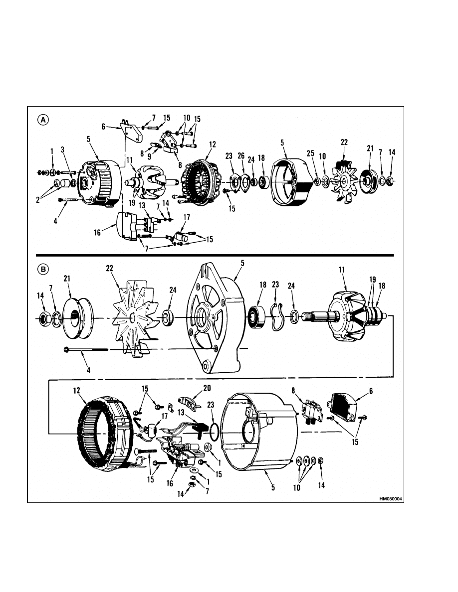
Figure 4. Type A Alternators, Exploded Views
6
2200 SRM 2
Alternator Repair
Legend for Figure 4
A. DELCO
B. MOTOROLA
1.
INSULATOR
2.
PLUG AND BEARING
3.
BEARING SEAL
4.
BOLT
5.
HOUSING
6.
VOLTAGE REGULATOR
7.
LOCKWASHER
8.
BRUSH AND HOLDER
9.
BRUSH SPRING
10. WASHER
11. ROTOR
12. STATOR
13. DIODES
14. NUT
15. SCREW
16. DIODE BRIDGE
17. CAPACITOR
18. BEARING
19. SLIP RINGS
20. TERMINAL
21. PULLEY
22. FAN
23. RETAINER
24. SPACER
25. SHIELD
26. GASKET
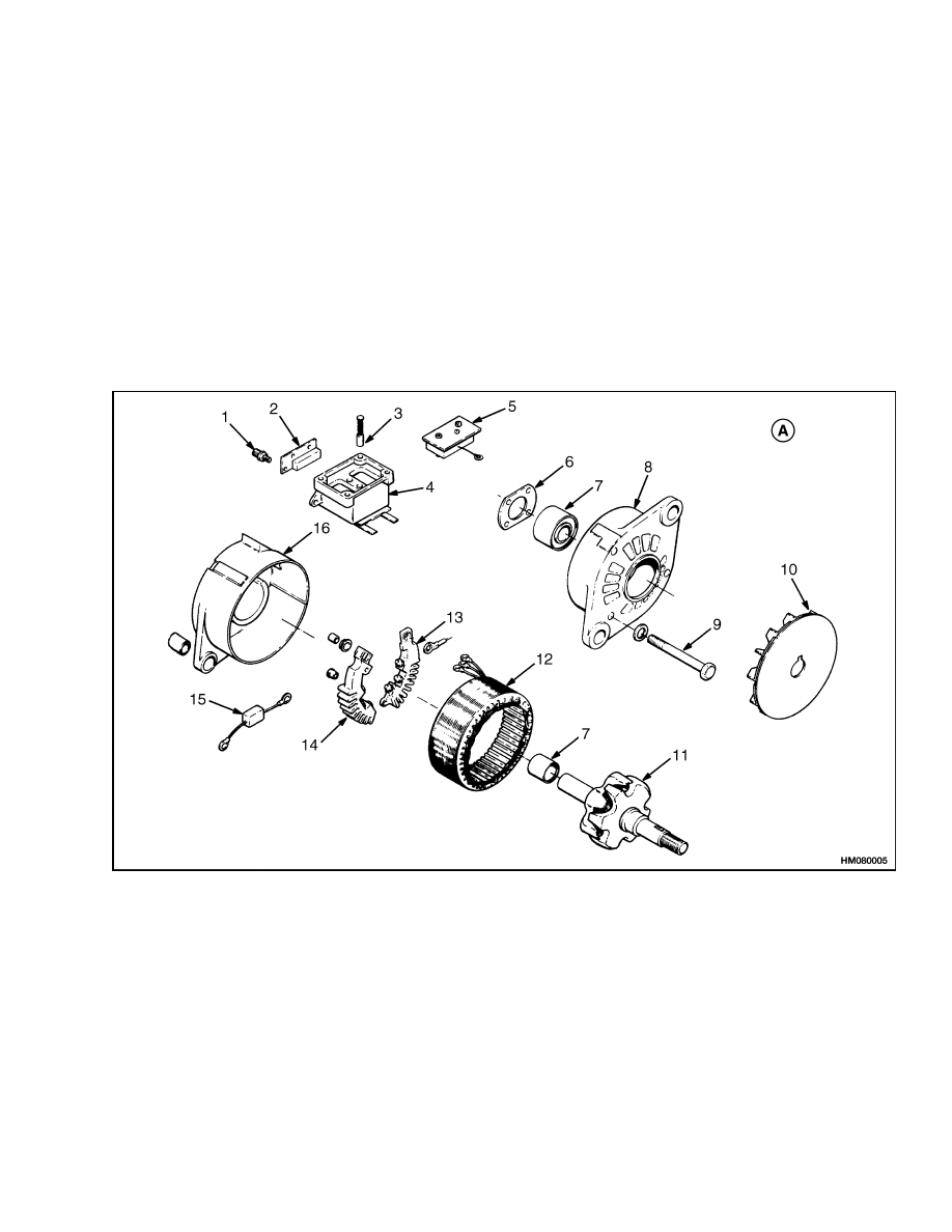
A. LEECE-NEVILLE
1.
TERMINAL
2.
DIODE SET
3.
BRUSH AND SPRING
4.
BRUSH HOLDER
5.
VOLTAGE REGULATOR
6.
BEARING RETAINER
7.
BEARING
8.
FRONT HOUSING
9.
BOLT
10. FAN
11. ROTOR
12. STATOR
13. NEGATIVE DIODE BRIDGE
14. POSITIVE DIODE BRIDGE
15. FILTER CAPACITOR
16. REAR HOUSING
Figure 5. Type A Alternator, Exploded View
7
Alternator Repair
2200 SRM 2
ALTERNATOR TYPE B
Remove and Disassemble
WARNING
Always disconnect the battery ground cable be-
fore making repairs to prevent possible dam-
age and injury. Install a tag on the battery ter-
minal so that no one connects the cable on the
terminal.
NOTE: Use the Troubleshooting and General Check
and Adjustment, Low Output Check (Type A or Type
B), High Output Check (Type A or Type B), Brushes
Circuit Check, Diodes Check, Diode Bridge Check,
Rotor Field Winding Check, Stator Windings Check,
and Voltage Regulator Check procedures of this SRM
before starting any repair procedures. Make sure
that repair or replacement of that part is necessary
before removal, disassembly, or replacement of the
part.
NOTE: There are some checks of the alternator that
are done with the alternator on the engine.
See
General Check and Adjustment, Low Output Check
(Type A or Type B), High Output Check (Type A
or Type B), Brushes Circuit Check, Diodes Check,
Diode Bridge Check, Rotor Field Winding Check,
Stator Windings Check, and Voltage Regulator
Check procedures of this SRM before starting any
removal or repair procedures.
1.
Disconnect the battery ground cable. See Fig-
ure 6, Figure 7, and Figure 8. Install labels and
disconnect the wires at the alternator. Discon-
nect the wire connector. Loosen the alternator
mount capscrews and remove the drive belt. Re-
move the capscrews that hold the alternator to
the engine.
2.
Put a mark on each housing and on the stator for
correct alignment during assembly. Remove the
bolts that hold the housings together. Separate
the housings and stator.
3.
Put the rotor in a vise that has soft jaws. Do not
tighten the vise to cause rotor distortion. Use a
socket wrench to remove the pulley nut. Remove
the pulley, collar, fan, outside collar, front hous-
ing, and inside collar from the rotor.
NOTE: The cover must be replaced if the parts will
be removed from the stator. If necessary, remove the
stator as described in Step 4 and Step 5.
4.
Use a punch to remove the rivets or pins that
fasten the cover. Remove the cover for access to
the stator leads. Discard the cover. See Figure 7.
5.
Cut the stator leads as close to the connectors as
possible. Install labels on the leads for correct
connection during assembly and remove the sta-
tor from the rear housing.
6.
Use a punch to remove the three baffle pins and
remove the baffle. See Figure 7.
NOTE: Carefully make a note of the sequence of re-
moval of parts in Step 7 and Step 8 for correct instal-
lation. Also make a note of all types of connections
(crimp, soldered, or welded) as well as all mechanical
fasteners.
7.
Remove the three mount screws and "BAT" ter-
minal nut. See Figure 8. Lift the brush holder,
voltage regulator, and diode bridge from the
housing.
8.
Open the crimps or use a soldering iron and
disconnect the connectors to separate the brush
holder, voltage regulator, and diode bridge.
9.
If the bearing will be replaced in the rear hous-
ing, remove the bearing and retainer ring.
Clean
WARNING
Compressed air can move particles so that they
cause injury to the user or to other personnel.
Make sure that the path of the compressed air
is away from all personnel.
Wear protective
goggles or a face shield to prevent injury to the
eyes.
CAUTION
Never use solvent on the parts of the alternator.
NOTE: If necessary, use fine abrasive cloth to polish
the slip rings. The abrasive cloth must be number
500 to 600. Remove all dust. Turn the rotor while
polishing the slip rings.
Use compressed air to remove dirt from the alterna-
tor. Clean the brushes and slip rings with a clean,
dry cloth.
8
2200 SRM 2
Alternator Repair
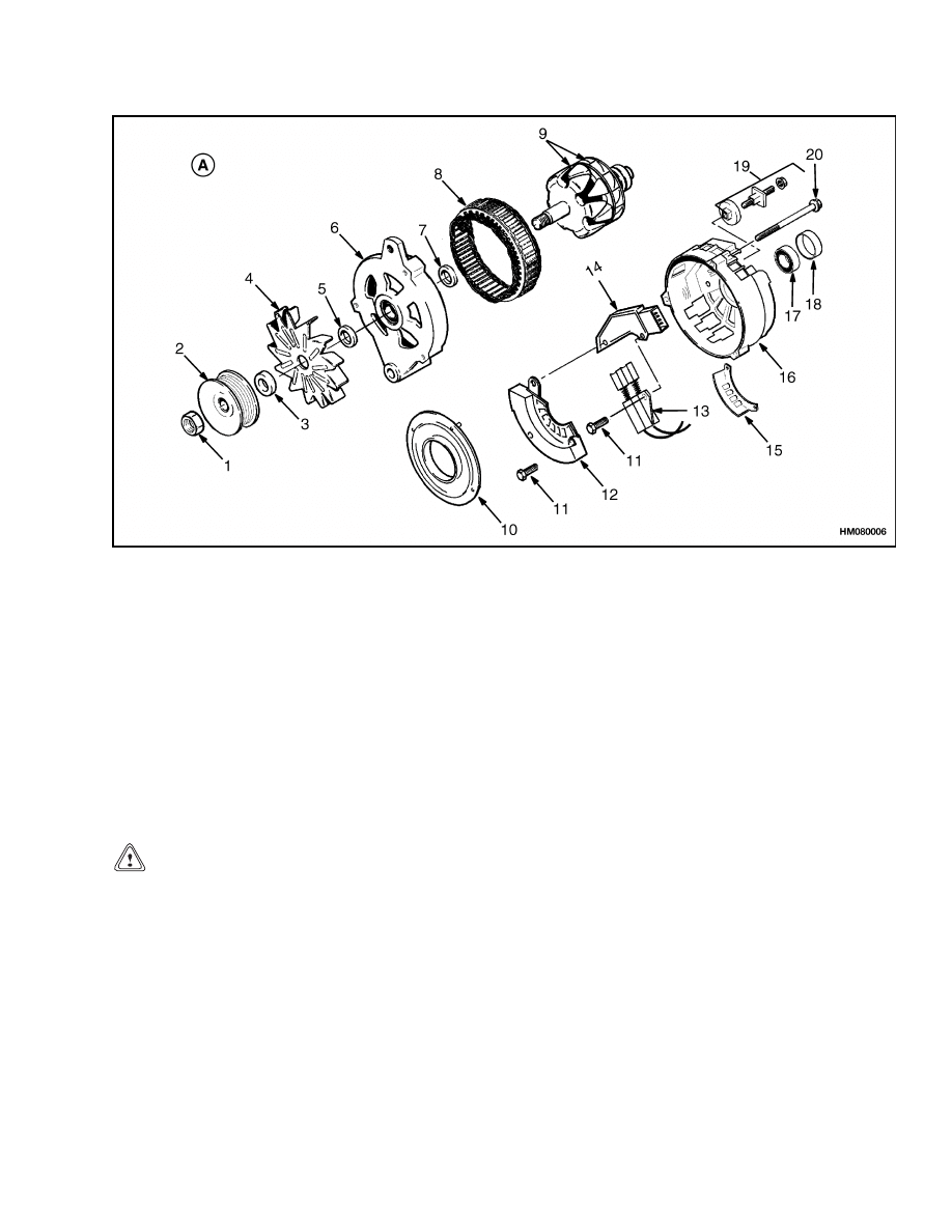
A. DELCO
1.
NUT
2.
PULLEY
3.
COLLAR
4.
OUTSIDE FAN
5.
OUTSIDE COLLAR
6.
FRONT HOUSING
7.
INSIDE COLLAR
8.
STATOR
9.
ROTOR AND FAN
10. BAFFLE
11. SCREW
12. DIODE BRIDGE
13. BRUSHES AND HOLDER
14. VOLTAGE REGULATOR
15. COVER
16. REAR HOUSING
17. BALL BEARING
18. RETAINER RING
19. TERMINAL SET
20. BOLT
Figure 6. Type B Alternator, Exploded View
Assemble
1.
If the bearing was removed from the rear hous-
ing, install a new retainer ring. See Figure 6.
CAUTION
The bearing is not completely installed until
Step 11 is complete.
2.
Install a new bearing by pushing on the new
bearing outer race until the bearing hits the
bottom in the rear housing.
3.
Assemble the voltage regulator, diode bridge, and
brush holder on a flat surface. Put crimps in the
connectors or solder the connectors to fasten and
connect the parts as originally assembled. Use a
pin to hold the brushes in the brush holder.
4.
Put a thin coating of silicon grease on the inside
of the rear housing under the diode bridge.
5.
Install the bridge, regulator, and brush holder
assembly in the rear housing and install the
screws as removed during disassembly.
6.
Install the baffle and use a punch to fasten the
pins.
7.
Align the marks made during disassembly and
install the stator in the rear housing. Use pliers
on the connectors of the diode bridge to keep heat
from the diodes. Use a soldering iron to connect
the stator leads to the connectors.
9
Alternator Repair
2200 SRM 2
NOTE: TYPE B ONLY.
1.
REAR HOUSING
2.
COVER
3.
COVER RIVETS
OR PINS
4.
BAFFLE PINS
5.
BOLTS TO FASTEN
HOUSINGS
TOGETHER
Figure 7. Outside Rear Housing
8.
Install a new cover using rivets or pins to fasten
the cover to the rear housing.
9.
If necessary, install the bearing in the front hous-
ing. Put the rotor in a vise with soft jaws and in-
stall the inner collar, front housing, outer collar,
fan, collar pulley, and nut on the rotor. Tighten
the nut to 54 to 108 N•m (40 to 80 lbf ft).
10. Align the front and rear housings using the
marks made during disassembly. Push on both
the inner and outer races of the rear bearing
to push the two housings and stator together.
Install the three bolts that fasten the alternator
together.
11. Push on both the inner and outer race of the rear
bearing so that the outer race is 1.9 to 2.2 mm
(0.075 to 0.087 in.) below the surface of the rear
housing.
Install
1.
Install the alternator in the bracket on the en-
gine and adjust the tension of the belt.
2.
Connect all wires and the connector according to
the labels made during removal. Also see the
schematic diagram for your alternator in Fig-
ure 2. Make sure all wires are connected cor-
rectly and all fasteners are tight. See Figure 7.
3.
Check the indicator light or the ammeter to check
the operation of the alternator. The indicator
light can also be ON if the alternator output is
too high on Type B alternators.
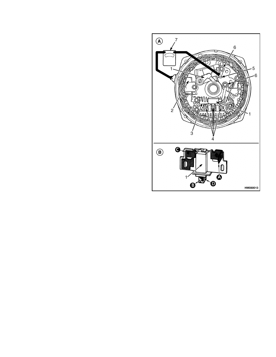
NOTE: TYPE B ONLY.
1.
REAR HOUSING
2.
VOLTAGE
REGULATOR
3.
BRUSH HOLDER
4.
DIODE BRIDGE
5.
TERMINALS FOR
STATOR LEADS
6.
NUT ON "BAT"
TERMINAL
7.
MOUNT SCREWS
8.
SOLDERED
OR WELDED
CONNECTOR
9.
BRUSH PIN
Figure 8. Inside Rear Housing
10
2200 SRM 2
Low Output Check (Type A or Type B)
General Check and Adjustment
There are no adjustments for the alternator or
most regulators.
One Delco alternator and the
Leece-Neville alternator has a voltage adjustment.
Always check the general condition of the complete
system before doing a complete check on each part.
Check the general condition of the following parts:
(1) battery, (2) battery cables and connections, and (3)
alternator and regulator wires and connectors. Also
check the condition and tension of the fan belt for the
alternator.
CAUTION
NEVER operate the engine if the alternator
output BAT terminal is not connected to the
battery.
Do not short-circuit or connect jumper wires to
any of the alternator terminals unless told to by
the procedures.
Make sure polarity is correct before connect-
ing a battery charger or another battery.
Remove the battery cables and clean the terminals
and cable connectors. Inspect the insulation on the
wires. Make sure all the fasteners and connections
are clean and tight. If necessary, use a water and
soda solution to clean the top of the battery. Do NOT
remove the cell caps or permit the water and soda
solution to get in the battery.
WARNING
Put the transmission in NEUTRAL. Apply the
parking brake.
CAUTION
Do not change the polarity of the circuits. Do
not connect any wires in the circuits, except as
described in these instructions. Never connect
the wire from the terminal marked "BAT" to an
open circuit.
When connecting a charger or another battery, con-
nect the positive terminals to the positive terminal
of the battery. Then connect the negative terminal
to a clean metal part of the engine. Disconnect the
charger or other battery in the reverse order. Prob-
lems in the charging circuit are indicated by one or
more of the following:
• The starter motor turns slowly. The battery voltage
is low because of low alternator output or a bad
battery.
• The specific gravity readings are low. Battery is
not fully charged or is damaged.
• The battery uses more than 30 ml (1 oz) of water
per cell per month. The alternator output is too
high.
The two problems of the charging circuit are low
output and high output. Low output causes a low
battery and difficult starting. A high output causes
heating of the battery and evaporation of water
from the electrolyte. The following two checks will
find out if the alternator, regulator, or wiring has a
charging fault. The two checks will also find out if
the charging system has a correct output. Do the
following two checks before removal, disassembly, or
replacement of alternator or regulator.
NOTE: Information on alternators manufactured
outside the United States is in the SRM (service
repair manual) sections for lift trucks that use those
alternators.
Low Output Check (Type A or Type B)
CAUTION
Do not connect the wire from the "BAT" termi-
nal to the electrical ground.
NOTE: Make sure the wire from the voltmeter makes
contact with each terminal on the alternator.
1.
Connect a voltmeter between the BAT terminal
and the electrical ground. Turn the key switch to
the ON position and check the reading.
2.
Connect a voltmeter to the field terminal and
the regulator terminal. Follow the procedure in
Step 1 and check the readings.
3.
If there are no readings on the voltmeter during
Step 1 and Step 2, check for an open circuit be-
tween each terminal and the battery.
4.
If there are readings on the voltmeter during
Step 1 and Step 2, disconnect the cable for the
electrical ground on the battery.
11
Low Output Check (Type A or Type B)
2200 SRM 2
5.
Make connections to the Type A alternator as
shown in Figure 9.
Make connections to the
Type B alternator as shown in Figure 10.
6.
Connect the cable for the electrical ground on the
battery.
7.
Connect a carbon pile across the terminals of the
battery.
8.
Run the engine at 2000 to 2500 rpm. Adjust the
carbon pile until the maximum charging rate is
reached.
9.
Read the value of the maximum charging rate
shown on the alternator housing or in the sec-
tion Capacities and Specifications for your
lift truck. Read the ammeter. The reading on
the ammeter must be within 10% of the maxi-
mum value.
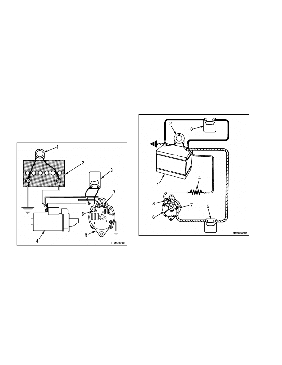
NOTE: TYPE A ONLY.
1.
CARBON PILE
2.
BATTERY
3.
AMMETER
4.
STARTER
5.
ALTERNATOR
6.
BAT TERMINAL
7.
FIELD TERMINAL
Figure 9. Alternator Output Check
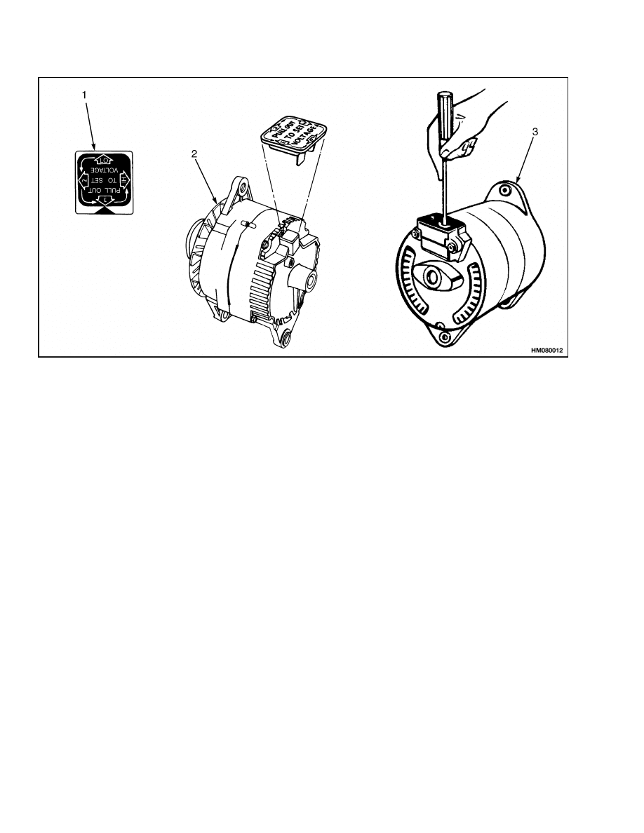
10. If the ammeter reading is within 10%, the alter-
nator is in good condition. Check the starter or
wires for problems. Some alternators on larger
lift trucks have a voltage adjustment. See Fig-
ure 12. For alternators with the voltage adjust-
ment, do Step a to set the voltage:
a. The voltage setting can be increased by
changing the position of the adjustment
plug. LO is the lowest voltage setting. 2 is
medium low and 3 is the medium setting.
The voltage setting is highest when HI is
aligned with the arrow on the alternator.
Change the setting as necessary.
NOTE: TYPE B ONLY.
1.
BATTERY
2.
CARBON PILE
3.
VOLTMETER
4.
RESISTOR (35
OHM 5 WATT TO
500 OHM 1/2 WATT)
5.
AMMETER
6.
ALTERNATOR
7.
BAT TERMINAL
8.
CONNECT TO L
TERMINAL
Figure 10. Alternator Output Check
12
2200 SRM 2
High Output Check (Type A or Type B)
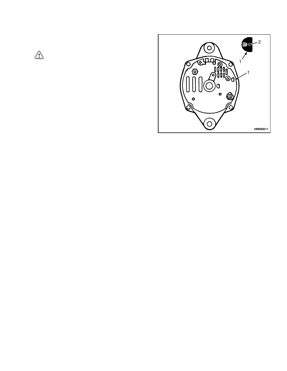
11. On Type A Delco alternators, do the following
checks:
CAUTION
Do not push the screwdriver into the hole for
more than 25 mm (1 in.).
a. If the output shown is not within 10%, put a
screwdriver into the hole shown in Figure 11.
b. Run the engine at 2000 to 2500 rpm. Adjust
the carbon pile until the maximum charging
rate is reached.
c.
If the output is within 10%, check the field
winding. If the field winding is in good con-
dition, replace the voltage regulator.
d. If the output is not within 10%, check the
wires to the brushes, diodes, diode bridge,
field winding, and stator.
e.
Remove the screwdriver, ammeter, and vari-
able resistor.
NOTE: DELCO TYPE A SHOWN.
1.
HOLE
2.
MAKE SURE SCREWDRIVER TOUCHES
HOUSING AND METAL TAG.
Figure 11. Electrical Ground on Field Winding
High Output Check (Type A or Type B)
1.
Connect a voltmeter from the regulator terminal
to the electrical ground. Check the reading on
the voltmeter. See Figure 9 or Figure 10.
2.
If there are no readings, check for an open circuit
between the regulator terminal and the battery.
3.
If there is a reading, connect a voltmeter between
the BAT terminal and the electrical ground.
4.
Increase the engine speed until the maximum
voltage reading is reached.
5.
If the voltage shown is more than 15.5 volts on
a 12-volt system or 31 volts on a 24-volt system,
disassemble the alternator and do the remainder
of the checks. For alternators with the voltage
adjustment, do the following:
a. Delco alternator. The voltage setting can be
increased or decreased by changing the po-
sition of the adjustment plug. See Figure 12.
LO is the lowest voltage setting. 2 is medium
low and 3 is the medium setting. The voltage
setting is highest when HI is aligned with the
arrow on the alternator. Do not change the
setting when engine is operating. Change
the setting as necessary.
b. Leece-Neville alternator. Remove the screw
in the cover. See Figure 12. Start the engine.
Connect a voltmeter across the battery ter-
minals and use a screwdriver to adjust the
voltage.
13
Brushes Circuit Check
2200 SRM 2
1.
VOLTAGE ADJUSTMENT CAP SHOWN IN
MEDIUM HIGH (3) POSITION.
2.
DELCO TYPE A
3.
LEECE-NEVILLE
Figure 12. Voltage Adjustment
Brushes Circuit Check
DELCO ALTERNATORS
1.
Use an ohmmeter that has a 1.5 volt cell. (Use
the lowest range scale.) Connect the ohmmeter
from the clip for the brushes to the metal hous-
ing. Make the test, then connect the ohmmeter
leads in the reverse direction and test again.
2.
If both readings are zero, either the wire or the
clip for the brushes has a short circuit to ground,
or the voltage regulator has damage.
3.
The cause of the problem can also be a missing
washer, a missing sleeve on a screw, or a dam-
aged insulator. See Figure 13. Remove the screw
and inspect the insulator. If the insulator is in
good condition, do Step 4, Step 5, and Step 6.
4.
Connect the ohmmeter from the wire of the
diodes to the housing.
5.
If the reading is zero on the ohmmeter, either the
wire to the diodes has a short circuit to ground,
or the voltage regulator has damage.
6.
The cause of the problem can be a missing
washer, a missing sleeve on a screw, or a dam-
aged insulator. Remove the screw and inspect
the insulator. If the insulator is in good condi-
tion, replace the voltage regulator.
14
2200 SRM 2
Brushes Circuit Check
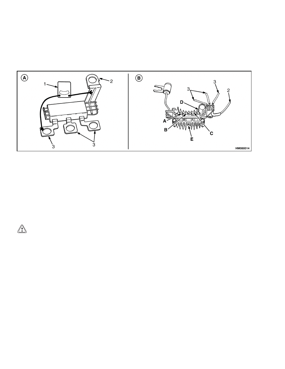
MOTOROLA ALTERNATORS
1.
Use an ohmmeter or a 12-volt test lamp to check
the brushes as shown in Figure 13.
2.
For correct operation, there must be continuity
between A to B and C to D. There must be no con-
tinuity from A to D or from C to B. See Figure 13.
If there is continuity, the brushes are connected
to the wrong terminal.
A. DELCO
B. MOTOROLA
1.
BRUSH HOLDER
2.
CAPACITOR
3.
DIODE BRIDGE
4.
NUTS
5.
DIODES
6.
INSULATOR
WASHERS
7.
OHMMETER
Figure 13. Brushes Circuit Check
15
Diode Bridge Check
2200 SRM 2
Diodes Check
Use an ohmmeter with a 1.5 volt cell. Use the lowest
range scale. Connect one lead of tester to the com-
mon connector, and one lead to one of the three diode
connections. Make the test, then reverse the tester
leads and make the same test. If both readings are
the same reading, replace the diodes. A good diode
will show one high reading, and one low reading. See
Figure 14.
A. DELCO TYPE A
B. MOTOROLA
1.
OHMMETER
2.
COMMON FOR DIODE SET
3.
DIODE SET CONNECTIONS
Figure 14. Diodes Check
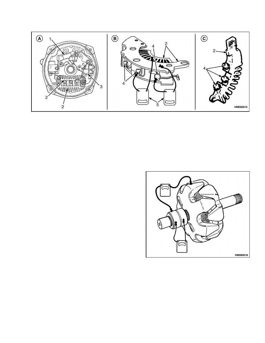
Diode Bridge Check
DELCO AND LEECE-NEVILLE
ALTERNATORS
CAUTION
Do not use a 120-volt test lamp to check the
diode bridge. Use a 12-volt tester to prevent
diode damage.
To check the diode bridge, connect the ohmmeter to
one heat sink and each of the three diodes in turn.
Check the readings, then connect the leads in the re-
verse direction. If both readings are the same, re-
place the diode. Repeat the test for the other heat
sink checking in both directions. See Figure 15.
MOTOROLA ALTERNATORS
Remove the wires for the diode set from the terminals
A, B, and C. Use an ohmmeter, diode tester, or 12-volt
test lamp to check between points A, B, and C, and
points D and E. Good diodes indicate continuity in
only one direction. If any parts are bad, replace the
diode bridge assembly. See Figure 14.
16
2200 SRM 2
Rotor Field Winding Check
A. DELCO TYPE A
B. DELCO TYPE B
C. LEECE-NEVILLE
1.
BRUSH HOLDER
2.
HEAT SINK
3.
VOLTAGE REGULATOR
4.
DIODE
5.
OHMMETER
Figure 15. Diode Bridge Check
Rotor Field Winding Check
Connect an ohmmeter to each slip ring and check for
open circuits. If the reading is high (infinity), the
winding has an open circuit. To check the resistance
of the field, connect the ohmmeter to the two slip
rings. The correct reading is 4.0 to 4.5 ohms. If the
reading is less than specified, there is a short circuit
in the windings. If the reading is more than speci-
fied, there is excessive resistance in the windings.
NOTE: Make sure the needle in the ohmmeter always
returns to zero correctly. The readings will change
when the temperature of the winding changes.
To check the electrical ground, connect the ohmmeter
between either slip ring and the electrical ground as
shown in Figure 16. Replace the rotor if the reading
is less than infinity.
Figure 16. Rotor Coil Checks
17
Troubleshooting
2200 SRM 2
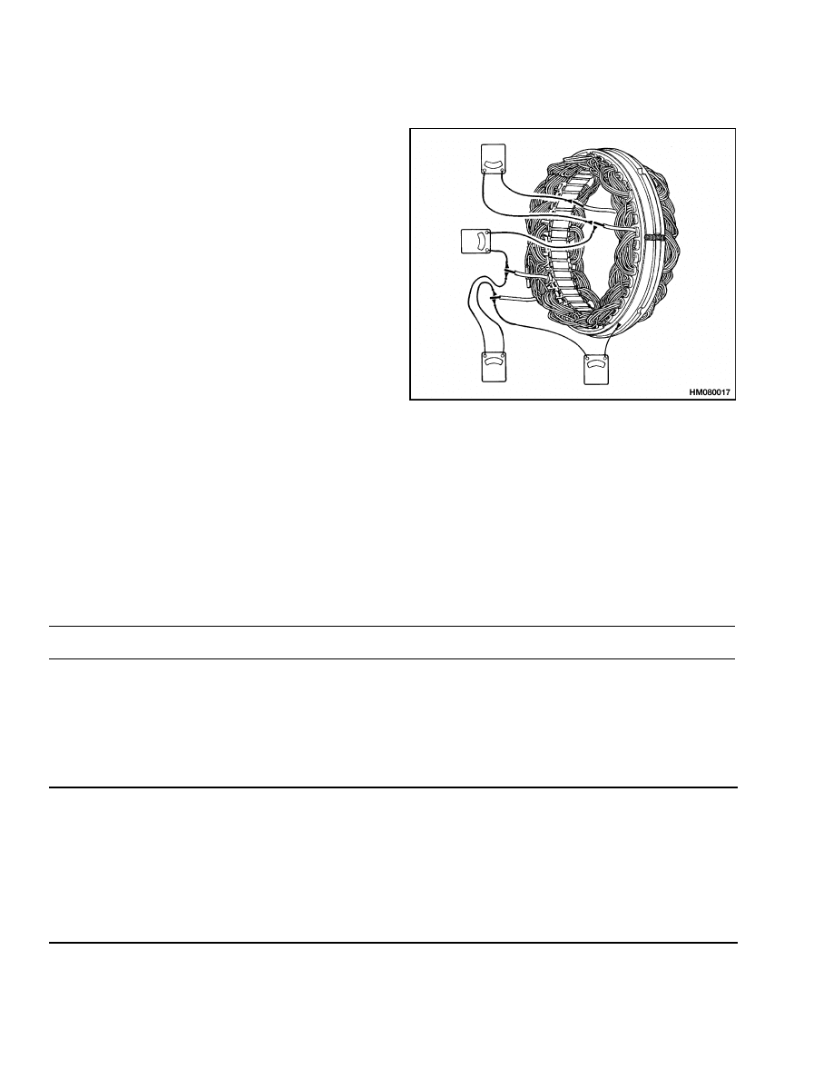
Stator Windings Check
To check the stator windings for electrical ground,
connect an ohmmeter as shown in Figure 17. There
must be no continuity between any of the stator ter-
minals and the metal housing.
To check the stator for open circuits, connect the ohm-
meter or test lamp between each pair of wires to the
stator as shown in Figure 17. If the test lamp does
not illuminate or the meter reading is high, the wind-
ings have an open circuit.
Figure 17. Stator Checks
Voltage Regulator Check
Use a voltage regulator test device. Do not use an ohmmeter. If the voltage regulator has damage, replace the
voltage regulator.
Troubleshooting
PROBLEM
POSSIBLE CAUSE
PROCEDURE OR ACTION
Battery is charged above
normal.
Alternator is not charging correctly.
Repair or install new parts.
Electrical ground in wire to brush or
clip.
Repair or install new parts.
High resistance in the circuit.
Repair or install new parts.
Battery uses more water
than normal.
Battery is charging more than nor-
mal.
Replace voltage regulator.
Alternator has damage in the field
windings, diodes, diode bridge, or
stator.
Install new parts.
Battery has damage or is too old.
Replace battery.
18

2200 SRM 2
Troubleshooting
PROBLEM
POSSIBLE CAUSE
PROCEDURE OR ACTION
There is no charge from the
alternator.
The brushes are worn or damaged.
Install new brushes.
Weak springs for brushes. Brushes
or brush holders do not move freely.
Install new parts.
Dirt on the slip rings.
Clean or install new parts.
There is no charge from the
alternator.
The indicator
light or ammeter indicates
a discharged condition when
the rpm is high and the load
is high.
There is an electrical ground in the
field winding.
Replace rotor or alternator.
Drive belt is not tight or is broken.
Adjust or replace drive belt.
Ammeter or the indicator
light indicates a discharged
condition at all speeds.
There is a short circuit in the diodes.
Install new parts.
There is an electrical ground at the
end of the windings.
Replace rotor or alternator.
The voltage regulator has damage.
Replace voltage regulator.
19

NOTES
____________________________________________________________
____________________________________________________________
____________________________________________________________
____________________________________________________________
____________________________________________________________
____________________________________________________________
____________________________________________________________
____________________________________________________________
____________________________________________________________
____________________________________________________________
____________________________________________________________
____________________________________________________________
____________________________________________________________
____________________________________________________________
____________________________________________________________
____________________________________________________________
____________________________________________________________
____________________________________________________________
____________________________________________________________
____________________________________________________________
20


TECHNICAL PUBLICATIONS
2200 SRM 2
12/04 (10/03)(9/02)(11/01)(2/01)(4/93)(7/87)(6/80)(6/78) Printed in U.S.A.
Document Outline
- toc
- Alternator with Regulator
- Safety Precautions Maintenance and Repair
- General
- Description
- Alternator Repair
- General Check and Adjustment
- Low Output Check (Type A or Type B)
- High Output Check (Type A or Type B)
- Brushes Circuit Check
- Diodes Check
- Diode Bridge Check
- Rotor Field Winding Check
- Stator Windings Check
- Voltage Regulator Check
- Troubleshooting
Wyszukiwarka
Podobne podstrony:
Starter 2200SRM0106 (12 2004) US EN
1494143 2200SRM0939 (12 2004) UK EN
1474823 2200SRM0781 (11 2001) US EN
1538373 2200SRM1065 (02 2004) UK EN
1559550 2200SRM1097 (10 2004) UK EN
1519772 2200SRM1016 (10 2004) UK EN
897495 2200SRM0514 (01 2004) UK EN
910110 2200SRM0143 (08 2004) UK EN
1564268 2200SRM1106 (01 2004) UK EN
1578950 2200SRM1119 (08 2004) UK EN
897556 1400SRM0542 (12 2003) US EN
1565183 2200SRM1110 (08 2004) UK EN
897928 2200SRM0625 (12 1996) UK EN
910442 8000SRM0231 (12 2004) UK EN
1556871 2200SRM1105 (01 2004) UK EN
więcej podobnych podstron