DRIVE AXLE
H1.50-1.75XM (S/H25-35XM)
[C010, D001, D010, E001];
H2.00XMS (S/H40XMS)
[C010, D001, D010, E001]
PART NO. 897556
1400 SRM 542

SAFETY PRECAUTIONS
MAINTENANCE AND REPAIR
• When lifting parts or assemblies, make sure all slings, chains, or cables are correctly
fastened, and that the load being lifted is balanced. Make sure the crane, cables, and
chains have the capacity to support the weight of the load.
• Do not lift heavy parts by hand, use a lifting mechanism.
• Wear safety glasses.
• DISCONNECT THE BATTERY CONNECTOR before doing any maintenance or repair
on electric lift trucks.
• Disconnect the battery ground cable on internal combustion lift trucks.
• Always use correct blocks to prevent the unit from rolling or falling. See HOW TO PUT
THE LIFT TRUCK ON BLOCKS in the Operating Manual or the Periodic Mainte-
nance section.
• Keep the unit clean and the working area clean and orderly.
• Use the correct tools for the job.
• Keep the tools clean and in good condition.
• Always use HYSTER APPROVED parts when making repairs. Replacement parts
must meet or exceed the specifications of the original equipment manufacturer.
• Make sure all nuts, bolts, snap rings, and other fastening devices are removed before
using force to remove parts.
• Always fasten a DO NOT OPERATE tag to the controls of the unit when making repairs,
or if the unit needs repairs.
• Be sure to follow the WARNING and CAUTION notes in the instructions.
• Gasoline, Liquid Petroleum Gas (LPG), Compressed Natural Gas (CNG), and Diesel fuel
are flammable. Be sure to follow the necessary safety precautions when handling these
fuels and when working on these fuel systems.
• Batteries generate flammable gas when they are being charged. Keep fire and sparks
away from the area. Make sure the area is well ventilated.
NOTE: The following symbols and words indicate safety information in this
manual:
WARNING
Indicates a condition that can cause immediate death or injury!
CAUTION
Indicates a condition that can cause property damage!

Drive Axle
Table of Contents
TABLE OF CONTENTS
General ...............................................................................................................................................................
Description .........................................................................................................................................................
Drive Axle Repair...............................................................................................................................................
Remove and Disassemble ..............................................................................................................................
Clean and Inspect ..........................................................................................................................................
Assemble and Install .....................................................................................................................................
Torque Specifications .........................................................................................................................................
Troubleshooting..................................................................................................................................................
This section is for the following models:
H1.50-1.75XM (S/H25-35XM) [C010, D001, D010, E001];
H2.00XMS (S/H40XMS) [C010, D001, D010, E001]
©2004 HYSTER COMPANY
i

"THE
QUALITY
KEEPERS"
HYSTER
APPROVED
PARTS
1400 SRM 542
General
General
This section has the description and repair proce-
dures for the drive axle, wheel bearings, and the
mounts for the axle housing. See Figure 1.
Information for the differential and ring and pin-
ion gears is in section Single-Speed Powershift
Transmission 1300 SRM 543.
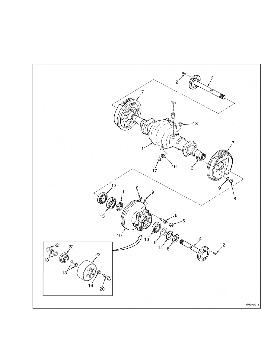
Figure 1. Drive Axle Parts
1

Drive Axle Repair
1400 SRM 542
Legend for Figure 1
1.
AXLE HOUSING
2.
CAPSCREW
3.
STUD
4.
AXLE SHAFT
5.
WHEEL NUT
6.
WHEEL STUD
7.
BRAKE ASSEMBLY
8.
NUT
9.
WASHER
10. HUB/BRAKE DRUM
11. OUTER SEAL
12. INNER SEAL
13. BEARING
14. LOCKPLATE
15. BREATHER
16. LEVEL PLUG
17. DRAIN PLUG
18. PLUG
19. WASHER (S25-35XM, S40XMS
ONLY)
20. CAPSCREW (S25-35XM,
S40XMS ONLY)
21. OIL SEAL
22. HUB (CUSHION TIRES)
23. TIRE/WHEEL (CUSHION
TIRES)
Description
The drive axle is mounted directly to the frame and is
held in place by two caps. These caps are fastened to
the frame of the lift truck by capscrews. See Figure 1.
The differential housing can move a small amount in
the axle mounts. The outer ends of the axle housing
are the mounts for the wheel bearings. The wheel
bearings are tapered-roller bearings with the cups
pressed into the hub/brake drum. The lock nut on
the end of the spindle holds and adjusts the wheel
bearings. The axle shafts are fastened to the hubs
by capscrews. The back plate and brake assembly
are fastened to the axle housing. The axle housing is
also the mounting for the mast.
The outer wheel bearing is lubricated with gear oil
from the differential housing. The inner wheel bear-
ing is lubricated with wheel bearing grease.
Drive Axle Repair
REMOVE AND DISASSEMBLE
WARNING
When putting the lift truck on blocks, make
sure surface is solid, even, and level.
Any
blocks used to support lift truck must be solid
and one piece.
1.
Put blocks on each side (front and back) of steer-
ing tires to prevent movement of lift truck.
2.
Raise lift truck and put blocks under frame so
that drive wheels just touch floor. Put blocks un-
der counterweight for stability.
3.
Remove mast assembly as described in Mast Re-
pairs 4000 SRM 522.
4.
Drain oil from differential.
WARNING
On machines with pneumatic tires, completely
remove air from tires before removing them
from lift truck. Air pressure in tires can cause
tire and rim parts to explode, which can cause
serious injury or death. Never loosen nuts that
hold together inner and outer wheel halves
when there is air pressure in tire.
5.
Remove wheels.
Remove capscrews that hold
axle shafts to brake drums. Remove axle shafts.
See Figure 1.
6.
Bend lock plate and remove the lock nut from
spindle. Remove washer and bearing cone. Slide
hub/brake drum from spindle. If assembly can-
not be removed easily, loosen brake shoes. Put
a screwdriver through hole in back plate to turn
adjuster wheel and loosen brake shoes. Pull ac-
tuator away from adjuster wheel while adjuster
wheel is turned up.
7.
Disconnect brake lines to wheel cylinders. Dis-
connect parking brake cables at parking brake
lever. Loosen cable clamps for parking brake ca-
bles.
8.
Put blocks under transmission housing.
The
blocks must reach from floor to bottom of trans-
mission.
This will prevent any movement of
the transmission after the mounting caps are
removed.
2
1400 SRM 542
Drive Axle Repair
WARNING
The axle housing is heavy. A lifting device must
be used to move the axle housing.
9.
Support center of axle housing with a transmis-
sion-type jack that has a minimum capacity of
115 kg (250 lb). The jack must have four wheels
and a flat platform that will properly support the
axle housing. Remove capscrews that hold axle
housing to transmission housing. Remove cap-
screws that hold mounting caps to frame.
10. Separate axle housing from transmission. Pull
axle housing out from lift truck.
11. Disassemble brake assembly as described in
Brake System 1800 SRM 540. Remove back
plate from mounts for axle housing.
CLEAN AND INSPECT
WARNING
Cleaning solvents can be flammable and toxic
and can cause skin irritation.
When using
cleaning solvents, always follow the solvent
manufacturer’s safety precautions.
1.
Clean all parts of drive axle with solvent.
2.
Inspect bearings and seals for damage. Spin-
dles must turn freely in mounts. Splines for axle
shafts must not be damaged. Replace any dam-
aged parts.
ASSEMBLE AND INSTALL
1.
Attach back plate to axle housing. See Figure 1.
Apply Loctite to mounting studs and tighten nuts
to 102 N•m (75 lbf ft). Assemble brake assembly
onto back plate as described in Brake System
1800 SRM 540.
WARNING
The axle housing is heavy. A lifting device must
be used to move the axle housing.
2.
Put sealant on mounting surface of axle hous-
ing.
Use jack described in Step 9 in Remove
and Disassemble section in this manual to install
axle housing on transmission and frame. Tighten
capscrews that attach transmission to axle hous-
ing. Attach mounting caps and tighten mounting
hardware to 72 N•m (53 lbf ft).
3.
Install new grease seals in hub. Install outer
seal with lip toward outer bearing. Install inner
bearing and seal. Put wheel bearing grease in
bearing that is between seals.
4.
Install hub/brake drum assembly on axle hous-
ing.
5.
Install outer bearing cone on axle housing. In-
stall washer and lock plate.
Install lock nut.
Tighten lock nut while rotating hub. Loosen lock
nut until hub turns freely. Tighten lock nut to
3.4 N•m (2.5 lbf ft) or until first alignment posi-
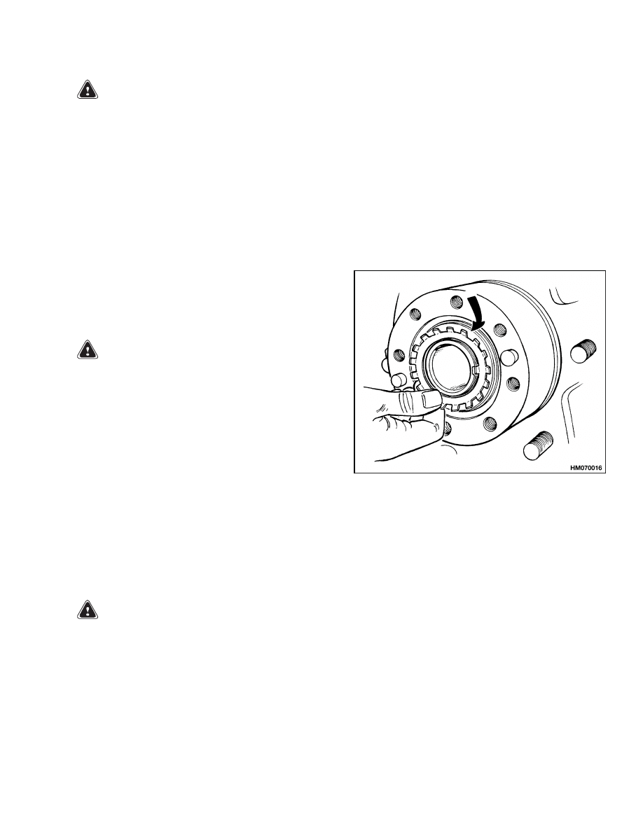
tion. Bend lock plate over lock nut. See Figure 2
and Figure 3.
Figure 2. Lock Plate Installation
6.
Connect brake lines to wheel cylinders. Connect
parking brake cables to parking brake lever. At-
tach cable clamps for parking brake cables.
7.
Adjust clearance of brake shoes as described in
Brake System 1800 SRM 540.
8.
Install the hub bolt and hub nut. Tighten the hub
nut to 124 N•m (91.4 lbf ft).
9.
Install wheels.
On the H1.50-1.75XM and
H2.00XMS (H25-35XM and H40XMS) models,
tighten wheel nuts to 196 to 216 N•m (144.5
to 159.3 lbf ft). On the S25-35XM and S40XMS
models, tighten capscrews for wheels to 129 N•m
(95 lbf ft).
10. Put sealant on flange of axle shaft. Install axle
shafts and capscrews.
Tighten capscrews to
66 N•m (49 lbf ft).
3
Drive Axle Repair
1400 SRM 542
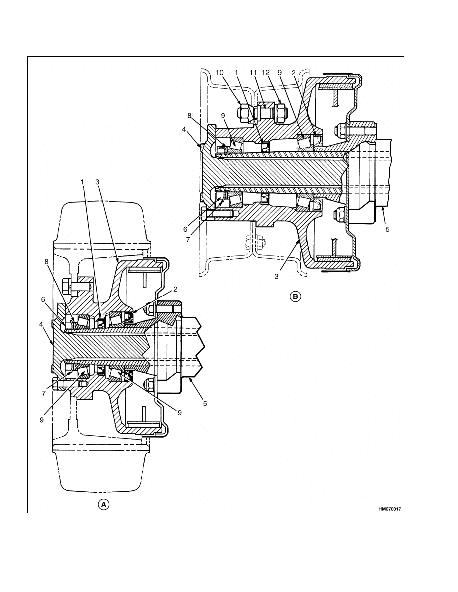
Figure 3. Hub Assembly
4

1400 SRM 542
Troubleshooting
Legend for Figure 3
A. S25-35XM, S40XMS
B. H1.50-1.75XM, H2.00XMS (H25-35XM, H40XMS)
1.
OUTER SEAL
2.
INNER SEAL
3.
HUB/BRAKE DRUM
4.
AXLE SHAFT
5.
DIFFERENTIAL HOUSING
6.
NUT
7.
LOCK PLATE
8.
WASHER
9.
BEARING CUP AND CONE
10. WHEEL NUT
11. HUB BOLT
12. HUB NUT
11. Install and tighten drain plug. Fill differential
housing with SAE 90 EP gear oil through fill
hole. Install plug. Remove air from brake sys-
tem as described in Brake System 1800 SRM
540.
12. Install mast as described in Mast Repairs 4000
SRM 522.
Torque Specifications
Back Plate to Axle Housing Nuts
102 N•m (75 lbf ft)
Axle Shaft Capscrews
66 N•m (49 lbf ft)
Hub Nut
124 N•m (91.4 lbf ft)
Wheel Nuts, H1.50-1.75XM, H2.00XMS
(H25-35XM, H40XMS)
196 to 216 N•m (144.5 to 159.3 lbf ft)
Wheel Capscrews, S25-35XM, S40XMS
129 N•m (95 lbf ft)
Troubleshooting
PROBLEM
POSSIBLE CAUSE
PROCEDURE OR ACTION
The lift truck will not move.
An axle shaft is broken.
Install new axle shaft.
The drive axle has leaks.
The drain plug or fill plug has dam-
aged threads, is loose, or is missing.
Repair threads, tighten plug, or in-
stall new plug as needed.
The O-rings or seals are damaged.
Install new O-rings and seals.
The drive axle housing is cracked.
Install new drive axle housing.
The drive axle makes noise.
The bearings are damaged.
Install new parts.
The brake assembly is damaged.
Repair brake assembly.
The oil level is low.
Fill as required. Check for leaks.
The axle mounting capscrews are
loose.
Tighten capscrews to the specified
torque.
5

NOTES
____________________________________________________________
____________________________________________________________
____________________________________________________________
____________________________________________________________
____________________________________________________________
____________________________________________________________
____________________________________________________________
____________________________________________________________
____________________________________________________________
____________________________________________________________
____________________________________________________________
____________________________________________________________
____________________________________________________________
____________________________________________________________
____________________________________________________________
____________________________________________________________
____________________________________________________________
____________________________________________________________
____________________________________________________________
____________________________________________________________
6


TECHNICAL PUBLICATIONS
1400 SRM 542
12/03 (2/01)(12/94)(9/93) Printed in U.S.A.
Document Outline
Wyszukiwarka
Podobne podstrony:
897493 1600SRM0512 (08 2003) US EN
1494953 1400SRM0944 (09 2003) UK EN
1498445 1400SRM0945 (09 2003) UK EN
1510463 1400SRM0984 (09 2003) UK EN
Alternator 2200SRM0002 (12 2004) US EN
1466211 2000SRM0754 (12 2003) UK EN
1494141 1800SRM0937 (12 2003) UK EN
897641 8000SRM0561 (08 2003) US EN
1483865 8000SRM0916 (12 2003) UK EN
897391 1400SRM0450 (09 2003) UK EN
910073 1400SRM0049 (09 2003) UK EN
1466247 1400SRM0731 (09 2003) UK EN
897493 1600SRM0512 (08 2003) US EN
więcej podobnych podstron