STEERING HOUSING
AND CONTROL UNIT
J2.00-3.20XM (J40-60XM) [A216];
N30XMH [C210];
E1.50-1.75XM (E25-35XM) [D114];
E2.00XMS (E40XMS) [D114];
E2.00-3.20XM (E45-65XM) [F108];
S2.00-3.20XM (S45-65XM) [D187]
PART NO. 897493
1600 SRM 512

SAFETY PRECAUTIONS
MAINTENANCE AND REPAIR
• When lifting parts or assemblies, make sure all slings, chains, or cables are correctly
fastened, and that the load being lifted is balanced. Make sure the crane, cables, and
chains have the capacity to support the weight of the load.
• Do not lift heavy parts by hand, use a lifting mechanism.
• Wear safety glasses.
• DISCONNECT THE BATTERY CONNECTOR before doing any maintenance or repair
on electric lift trucks.
• Disconnect the battery ground cable on internal combustion lift trucks.
• Always use correct blocks to prevent the unit from rolling or falling. See HOW TO PUT
THE LIFT TRUCK ON BLOCKS in the Operating Manual or the Periodic Mainte-
nance section.
• Keep the unit clean and the working area clean and orderly.
• Use the correct tools for the job.
• Keep the tools clean and in good condition.
• Always use HYSTER APPROVED parts when making repairs. Replacement parts
must meet or exceed the specifications of the original equipment manufacturer.
• Make sure all nuts, bolts, snap rings, and other fastening devices are removed before
using force to remove parts.
• Always fasten a DO NOT OPERATE tag to the controls of the unit when making repairs,
or if the unit needs repairs.
• Be sure to follow the WARNING and CAUTION notes in the instructions.
• Gasoline, Liquid Petroleum Gas (LPG), Compressed Natural Gas (CNG), and Diesel fuel
are flammable. Be sure to follow the necessary safety precautions when handling these
fuels and when working on these fuel systems.
• Batteries generate flammable gas when they are being charged. Keep fire and sparks
away from the area. Make sure the area is well ventilated.
NOTE:
The following symbols and words indicate safety information in this
manual:
WARNING
Indicates a condition that can cause immediate death or injury!
CAUTION
Indicates a condition that can cause property damage!
Steering Housing and Control Unit
Table of Contents
TABLE OF CONTENTS
General ...............................................................................................................................................................
Description .........................................................................................................................................................
Operation............................................................................................................................................................
Steering Wheel and Column Assembly Repair ................................................................................................
Steering Column Assembly, Remove ............................................................................................................
Steering Control Unit................................................................................................................................
Disassemble...........................................................................................................................................
Clean ......................................................................................................................................................
Assemble................................................................................................................................................
Install.....................................................................................................................................................
Steering Column Assembly, Install ..............................................................................................................
System Air Removal ..........................................................................................................................................
Remove ...........................................................................................................................................................
Troubleshooting..................................................................................................................................................
This section is for the following models:
J2.00-3.20XM (J40-60XM) [A216];
N30XMH [C210];
E1.50-1.75XM (E25-35XM) [D114];
E2.00XMS (E40XMS) [D114];
E2.00-3.20XM (E45-65XM) [F108];
S2.00-3.20XM (S45-65XM) [D187]
©2003 HYSTER COMPANY
i

"THE
QUALITY
KEEPERS"
HYSTER
APPROVED
PARTS
1600 SRM 512
Description
General
This section has the description and repair pro-
cedures for the steering housing and the steering
control unit.
Additional information on parts of
the steering system can be found in the following
sections: Steering Axle and Hydraulic System.
Description
This section covers the steering column assembly
used on the following series of lift trucks:
• J2.00-3.20XM (J40-60XM) (A216)
• N30XMH (C210)
• E1.50-1.75XM (E25-35XM), E2.00XMS (E40XMS)
(D114)
• E2.00-3.20XM (E45-65XM) (F108)
• S2.00-3.20XM (S45-65XM) D187)
This assembly uses a steering control unit with hose
connections on the bottom of the unit. See Figure 4.
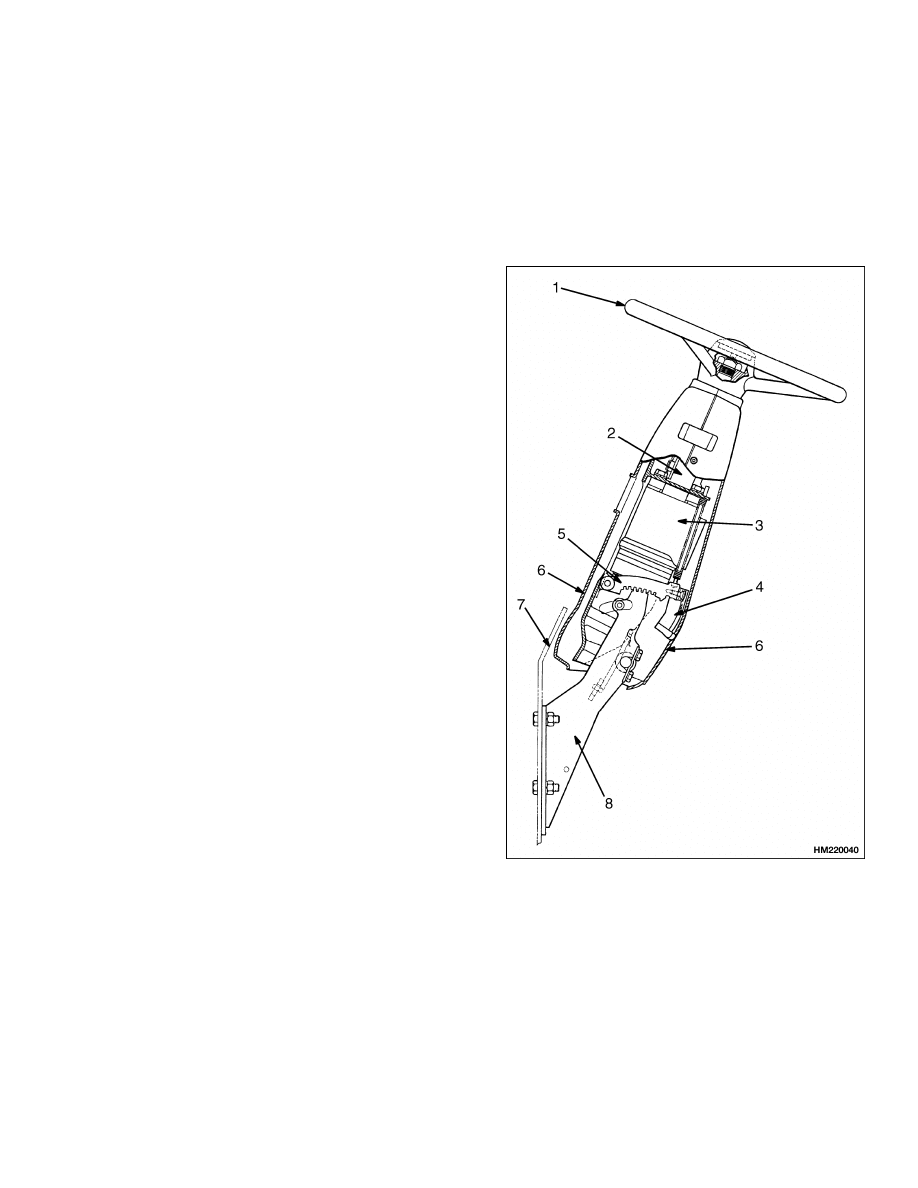
The steering housing has the mounts for the steering
column and the steering control unit. See Figure 1.
The steering wheel is installed on the steering col-
umn. The housing is adjustable and is held in posi-
tion by a latch. The position of the housing can be
changed for operator comfort. The steering housing
is also the mount for some control levers and the in-
strument cluster.
The steering system is a hydraulic system that does
not have a mechanical connection between the steer-
ing wheel and the steering axle. The control of the
steering is through a hydraulic circuit.
If the hydraulic pump for the steering system does
not operate, steering is still possible. A check valve
permits the steering control unit to control the steer-
ing cylinder. The lift truck is difficult to steer when
the steering pump is not operating, but the steer-
ing control unit can operate the steering cylinder and
make steering possible.
1.
STEERING WHEEL
2.
STEERING
COLUMN
3.
STEERING
CONTROL UNIT
4.
KNOB
5.
LATCH
6.
COVER
7.
COWL
8.
MOUNT
Figure 1. Steering Housing Assembly
1
Operation
1600 SRM 512
Operation
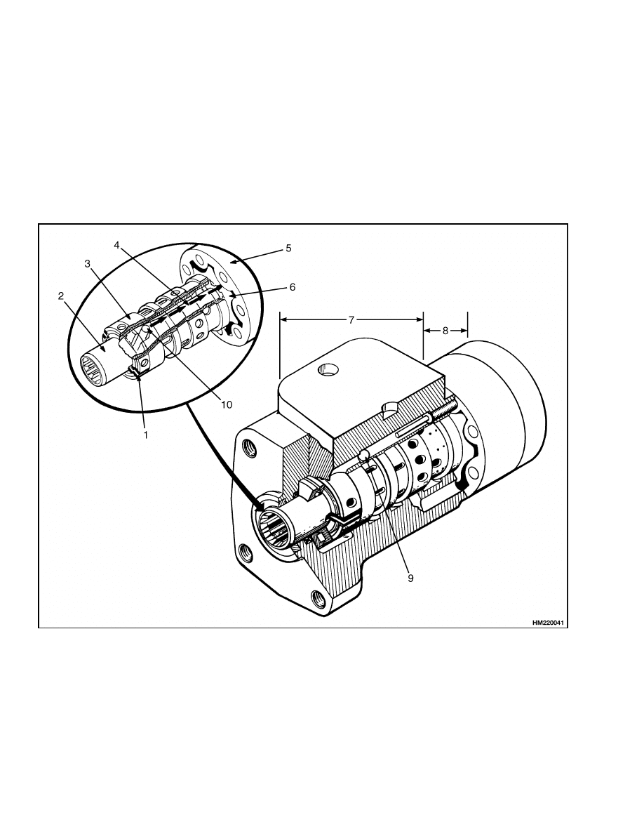
The steering control unit is a rotary valve operated by
the steering wheel. See Figure 2. During the steer-
ing operation, the steering control unit controls the
direction of flow and amount of oil that flows to the
steering cylinder. The steering cylinder in the axle
actuates the steering linkage to move the steer tires.
Hydraulic oil returns from the steering cylinder to
the steering control unit and then returns to the hy-
draulic tank.
Turning the steering wheel actuates three main
parts of the steering control unit: (1) the spool for
the control section, (2) the sleeve for the control
section, and (3) the rotor in the metering section.
When the steering wheel is not moving, the spool
and sleeve are held in the neutral (center) position
by springs. During this time, oil flows freely through
the steering control unit. The oil does not flow to the
steering cylinder.
1.
SPRING SET
2.
SPOOL
3.
SLEEVE
4.
CENTER SHAFT
5.
STATOR
6.
ROTOR
7.
CONTROL SECTION
8.
METERING SECTION
9.
CHECK BALL
10. CENTER PIN
Figure 2. Steering Control Unit
2

1600 SRM 512
Steering Wheel and Column Assembly Repair
As the steering wheel is turned, the spool just be-
gins to rotate. The springs try to move the sleeve
to keep the neutral position between the spool and
sleeve. However, the force necessary to turn the ro-
tor is greater than the pressure of the springs. The
springs begin to bend, letting the spool move a small
amount within the sleeve. The spool stops moving
when it touches the center pin. In this position, the
holes in the sleeve and the spool are aligned. Oil com-
ing into the control unit flows to the metering section.
More rotation of the steering wheel causes the spool
to rotate the pin. This action causes the rotation of
the sleeve and the rotor in the metering section. The
oil then flows to one side of the steering cylinder. Hy-
draulic oil from the other side of the steering cylin-
der returns through the control section of the steer-
ing control unit.
When the steering wheel stops moving, the meter-
ing action in the metering section also stops. The
neutral position springs return the sleeve to the neu-
tral position, stopping oil flow to or from the cylinder.
The pressure stays in the steering cylinder to keep
the steer tires in position. Oil from the pump flows
through the steering control unit to the tank or other
parts of the system. To return the steer wheels to the
straight position, the steering wheel must be rotated
in the opposite direction. The steering control unit
will operate as described, but all parts will rotate in
the opposite direction.
Steering Wheel and Column Assembly Repair
The upper end of the steering shaft has splines for the
steering wheel. See Figure 3, Figure 4, and Figure 5.
A large nut holds the steering wheel onto the steer-
ing shaft. The horn button is the cover for the center
of the steering wheel. The lower end of the steering
shaft has splines or a tang to engage the steering con-
trol unit. A push rod from the horn button actuates
the horn switch.
The steering column assembly is adjustable and held
in position by a latch. The position of the steering col-
umn assembly can be changed as needed for different
operator requirements. An access cover on the steer-
ing column gives access to the steering control unit
and horn switch.
STEERING COLUMN ASSEMBLY, REMOVE
CAUTION
Disconnect the negative battery cable on inter-
nal combustion trucks. Disconnect the battery
connector on electric trucks. Disconnect the
battery before removing any covers.
NOTE:
This procedure is for the removal of all com-
ponents of the steering column assembly. All compo-
nents are not often removed for a repair procedure.
Do only those steps of the procedure necessary to re-
move the required component.
1.
Attach a tag on the battery connector or negative
cable stating DO NOT CONNECT BATTERY.
Move the steering column to the most forward
position.
Remove the access cover from the
steering column. See Figure 3, Figure 4, and
Figure 5.
2.
Remove the capscrew that fastens the horn
switch to the housing of the steering column.
Move the horn switch away from the steering
column.
3.
Remove the horn cover. Lift the push rod and ad-
juster spool from the stop of the steering shaft.
Remove the large hex nut and remove the steer-
ing wheel from the shaft. A puller makes re-
moval of the steering wheel easier, but not all
steering wheels have puller holes.
4.
Some electric units have on-demand steering.
Remove the optical encoder and activator and
the brackets of the on-demand steering. Make
an identification of the electrical wires and dis-
connect them from the assemblies.
5.
Make an identification of the hydraulic hoses at
the steering control unit so they can be connected
correctly during assembly. Some hydraulic hoses
have fittings that will permit disconnection at
the steering control unit. Disconnect the other
hydraulic hoses at the base of the cowl, the
control valve, or the steering pump.
Remove
all mount clamps so that the hoses will turn
freely and not become twisted. Disconnect the
hydraulic hoses at the bottom of the steering
control unit. Install plugs at all hoses and ports
to prevent dirt from entering the steering hy-
draulic system.
3
Steering Wheel and Column Assembly Repair
1600 SRM 512
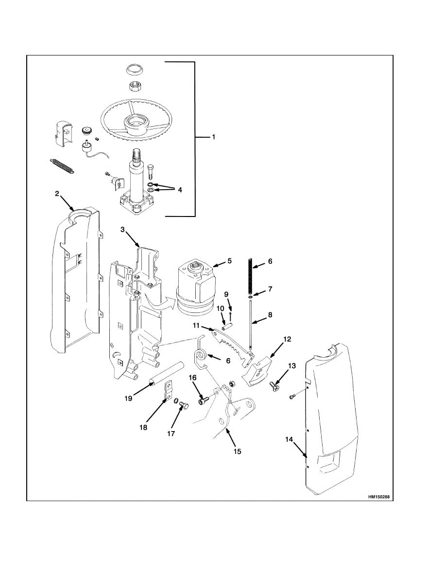
Figure 3. Steering Wheel and Steering Column Assembly
4

1600 SRM 512
Steering Wheel and Column Assembly Repair
Legend for Figure 3
NOTE: TYPICAL ARRANGEMENT ELECTRIC UNITS.
NOTE: ON-DEMAND STEERING IS USED ON ELECTRIC TRUCK MODELS ONLY.
1.
STEERING WHEEL, SHAFT, ON-DEMAND
STEERING PARTS, AND HORN SWITCH
2.
FRONT COVER
3.
BRACKET
4.
WASHERS
5.
STEERING CONTROL UNIT
6.
SPRING
7.
WASHER
8.
ROD
9.
COTTER PIN
10. PIN
11. LATCH
12. KNOB
13. SCREW
14. REAR COVER
15. MOUNT
16. ALLEN HEAD CAPSCREW
17. CAPSCREW
18. PLATE
19. PIVOT SHAFT
6.
If there is a display panel on the steering col-
umn housing, disconnect all plugs connected to
the display panel.
NOTE:
The repair procedures for the instrument
cluster for the H/S2.00-3.20XM (H/S40-65XM) and
H/S1.50-2.00XMS (H/S30-40XMS) model trucks are
in the section Instrument Cluster 2200 SRM 514.
NOTE:
The repair procedures for the instrument
cluster
for
the
E/J2.00-3.20XM
(E/J45-65XM),
J1.60-2.00XMT (J30-40XMT), and N30XMH are in
the section Electrical System 2200 SRM 560.
7.
Remove the capscrews, lockwashers, and lock
plates that fasten the steering column to the
pivots on the lift truck. Remove the steering col-
umn from the lift truck. Make sure the electric
wires and the hydraulic hoses are not damaged
as the steering column is removed.
8.
Do the following procedure to remove the steer-
ing shaft:
a. Move the plastic tube and washer toward the
steering control unit and compress the spring
for the horn switch. Then, remove the pin
that goes through the steering shaft and en-
gages the plastic tube.
b. Remove the external snap ring that holds
the bearing in the steering column. On units
that have on-demand steering, loosen the
setscrew in the gear on the shaft. The return
spring, washer, and tube are removed at the
same time as the steering shaft and bearing
are removed. Use a small pry bar at the bot-
tom of the steering shaft near the steering
control unit to remove the steering shaft and
bearing (also, return spring, washer, and
tube) from the steering column.
9.
Remove the four capscrews that hold the steering
control unit to the steering column. Remove the
four capscrews or nuts that fasten the steering
control unit to the bracket.
5
Steering Wheel and Column Assembly Repair
1600 SRM 512
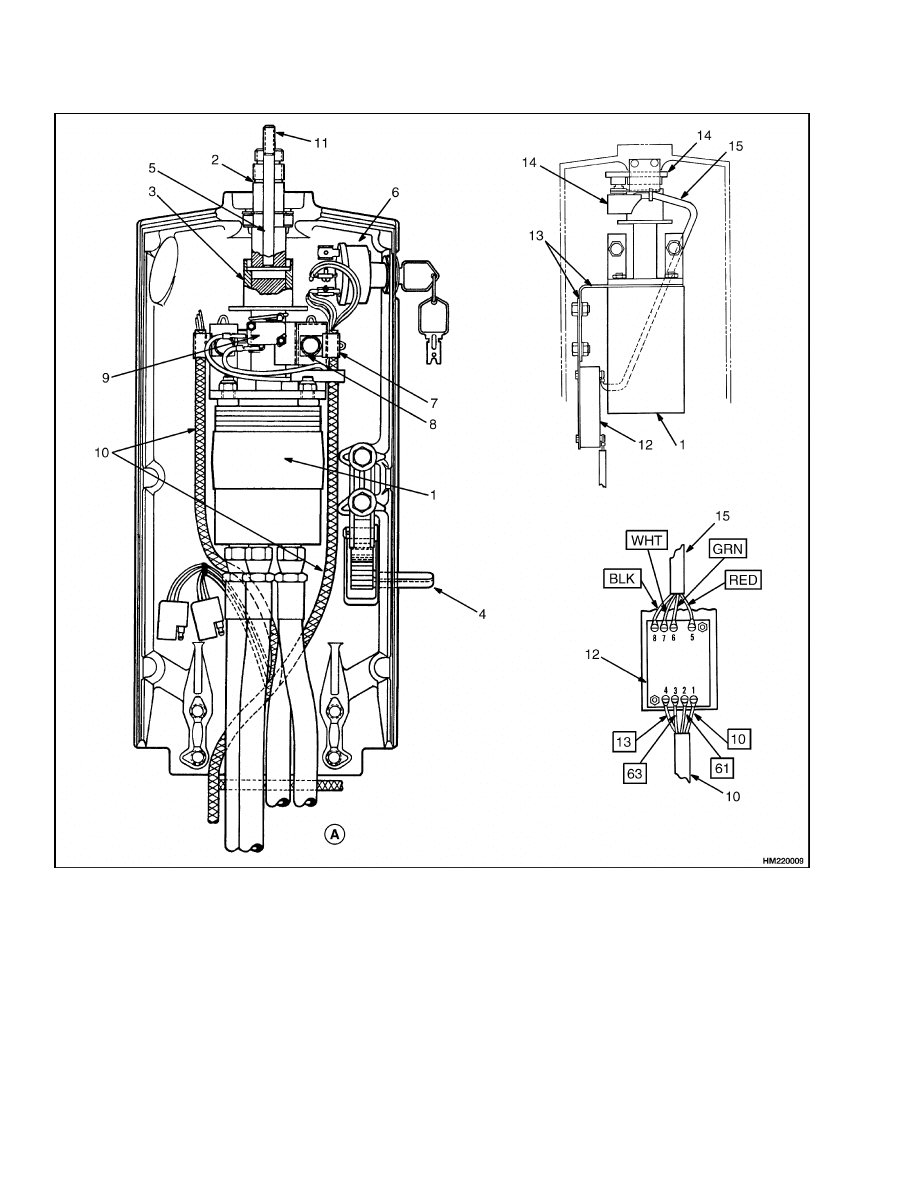
A. REAR VIEW
1.
STEERING CONTROL UNIT
2.
STEERING SHAFT
3.
PLASTIC TUBE
4.
LATCH
5.
PIN
6.
KEY SWITCH
7.
CLAMP
8.
BRACKET
9.
HORN SWITCH
10. LIFT TRUCK WIRE HARNESS
11. SOCKET HEAD SCREW
12. ACTIVATOR ASSEMBLY
13. BRACKET
14. OPTICAL ENCODER AND BRACKET
15. ENCODER/ACTIVATOR WIRE HARNESS
Figure 4. Steering Column Assembly
6
1600 SRM 512
Steering Wheel and Column Assembly Repair
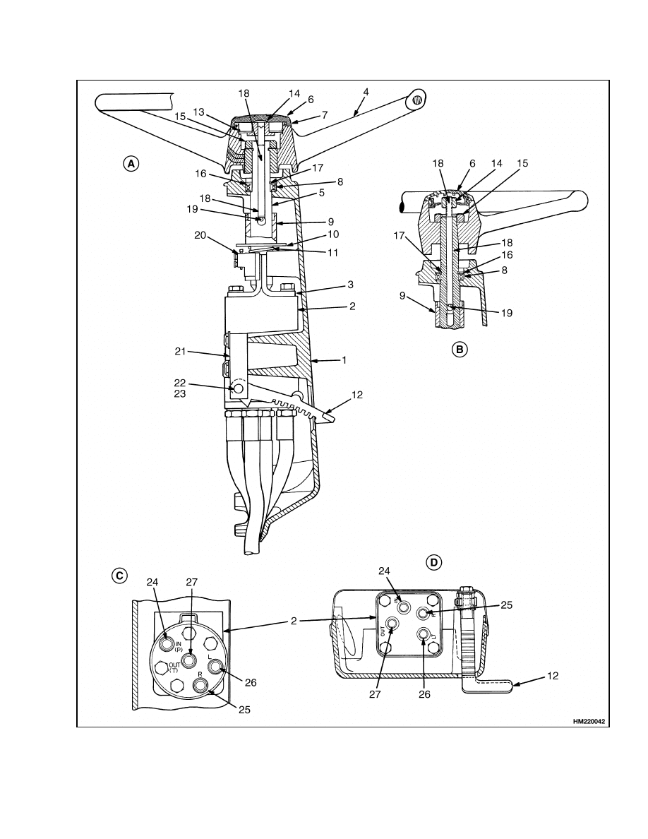
Figure 5. Steering Wheel and Steering Column Assembly
7
Steering Wheel and Column Assembly Repair
1600 SRM 512
Legend for Figure 5
A. SIDE VIEW
B. PETRI STEERING WHEEL
C. DANFOSS
D. TRW
1.
STEERING COLUMN
2.
STEERING CONTROL UNIT
3.
BRACKET
4.
STEERING WHEEL
5.
STEERING SHAFT
6.
HORN COVER
7.
BASE PLATE
8.
BEARING
9.
PLASTIC TUBE
10. PLASTIC WASHER
11. SPRING
12. LATCH
13. LOCK RING
14. ADJUSTER SPOOL NUT
15. STEERING WHEEL NUT
16. EXTERNAL SNAP RING
17. INTERNAL SNAP RING
18. PUSH ROD
19. PIN
20. HORN SWITCH
21. BRACKET
22. LATCH PIVOT PIN
23. SOCKET HEAD SCREW
24. INPUT
25. RIGHT TURN
26. LEFT TURN
27. RETURN
Steering Control Unit
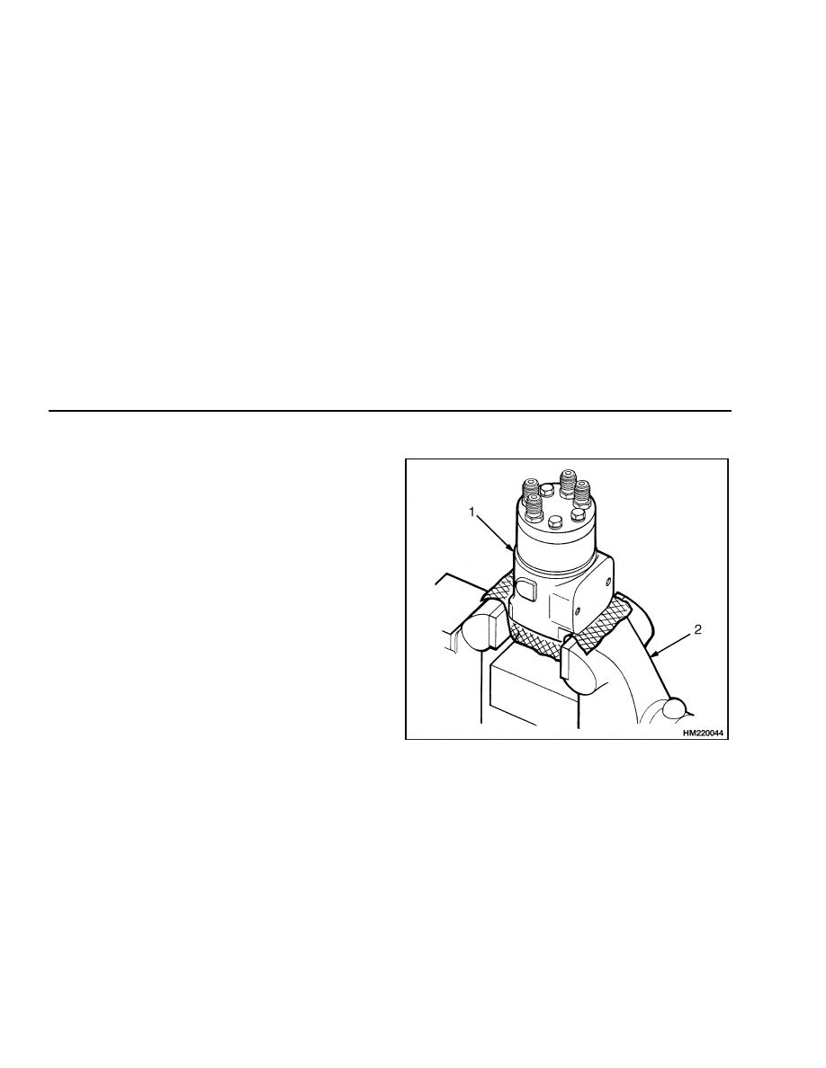
Disassemble
STEP 1.
Put the control unit in a vise with soft jaws. Make an
identification mark on the length of the control unit.
1.
STEERING CONTROL UNIT
2.
VISE
8
1600 SRM 512
Steering Wheel and Column Assembly Repair
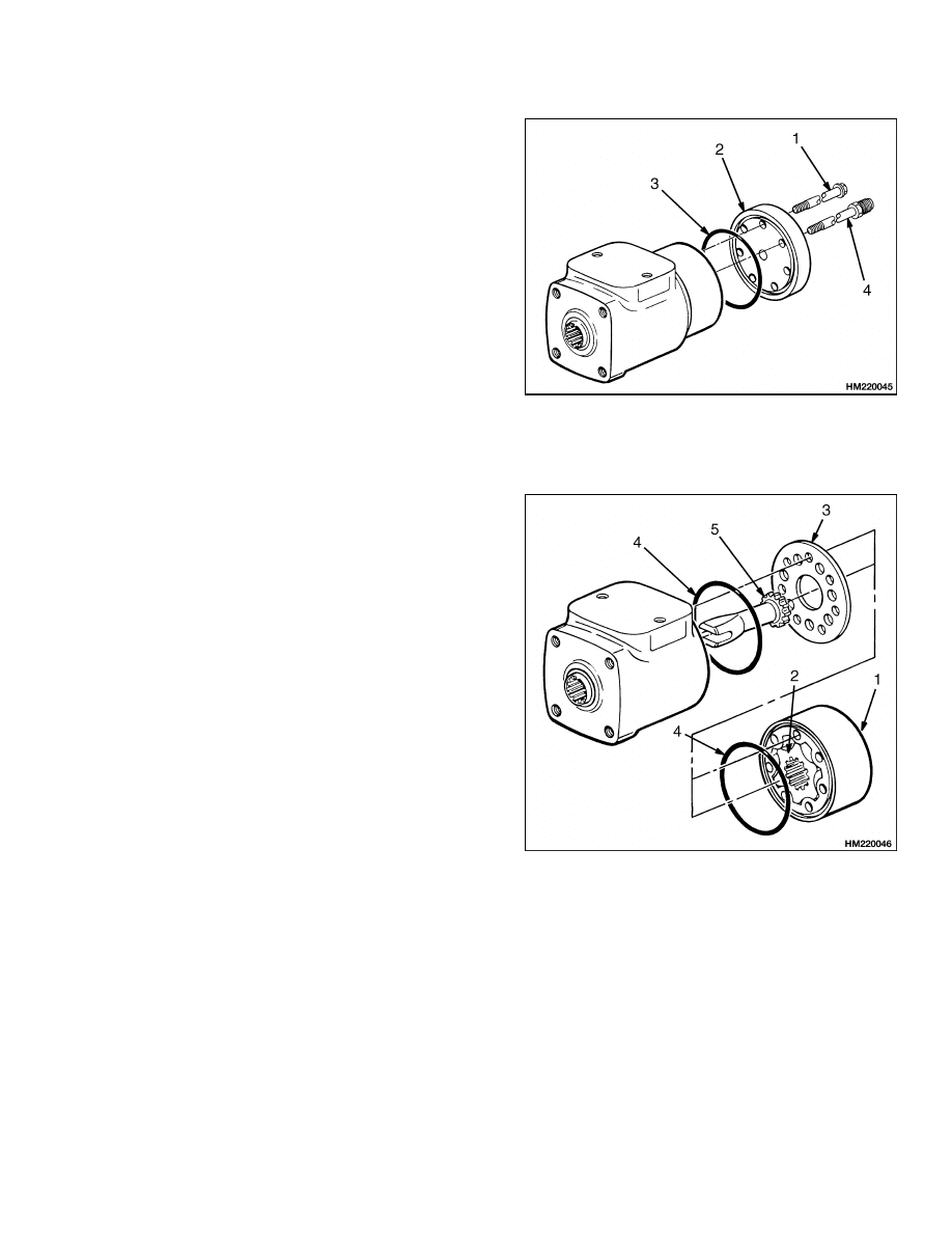
STEP 2.
Remove the cover on the bottom of the steering con-
trol unit. Remove the check ball.
1.
CAPSCREW
2.
COVER
3.
O-RING
4.
SPECIAL FITTING
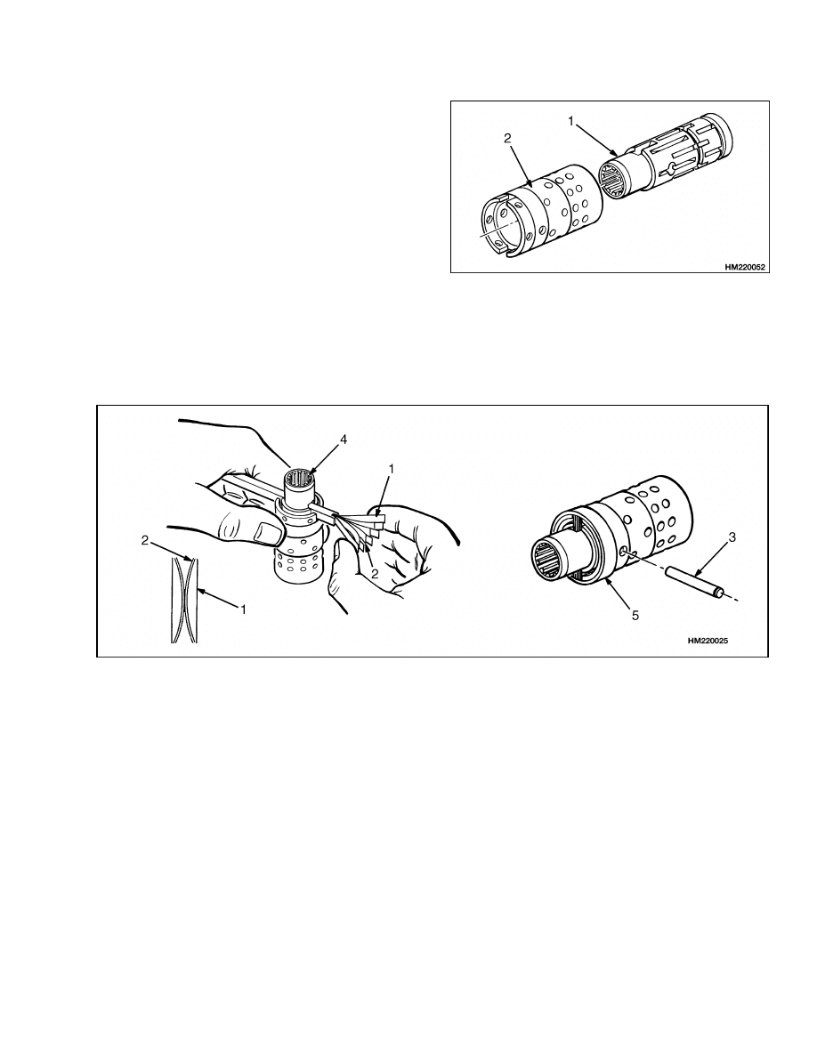
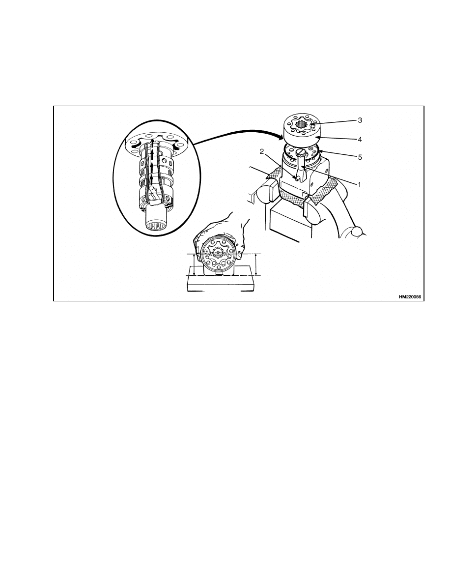
STEP 3.
Remove the stator, rotor, and port plate. Put a mark
on the stator so that the same side will be toward
the body of the control unit at assembly. Remove the
O-rings. Remove the center shaft.
1.
STATOR
2.
ROTOR
3.
PORT PLATE
4.
O-RING
5.
CENTER SHAFT
9
Steering Wheel and Column Assembly Repair
1600 SRM 512
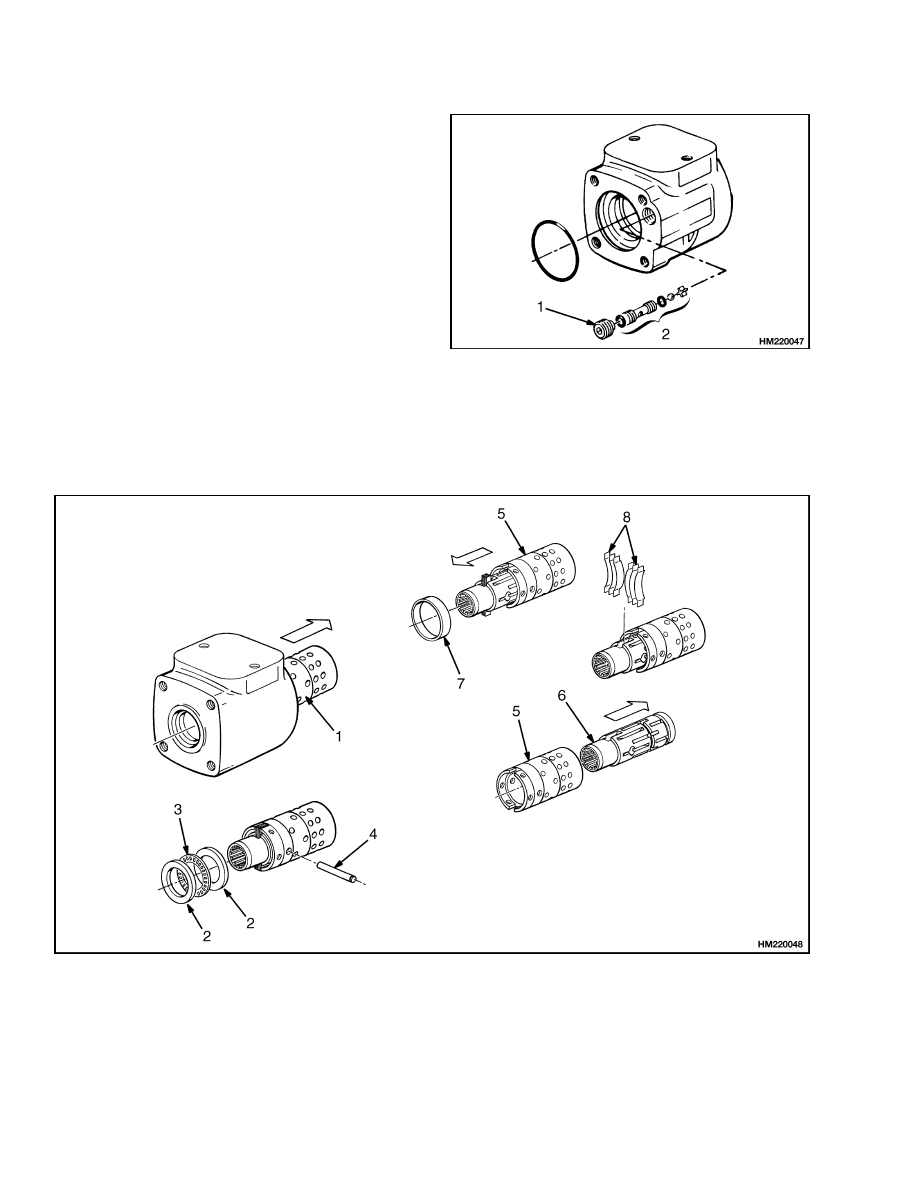
STEP 4.
Remove the screw for the check valve assembly. Re-
move the parts for the check valve. For some units,
the check ball is in the opposite end of the control
unit.
1.
SCREW
2.
CHECK VALVE ASSEMBLY
STEP 5.
Remove the spool and sleeve assembly. Remove the thrust bearing assembly from the spool. Push the center pin
from the sleeve. Carefully remove the spool from the sleeve. Rotate the spool slowly during removal. Remove
the ring from the sleeve. Remove the neutral position springs from the spool. Remove the seal from the housing.
1.
SPOOL AND SLEEVE ASSEMBLY
2.
THRUST WASHER
3.
THRUST BEARING
4.
CENTER PIN
5.
SLEEVE
6.
SPOOL
7.
RING
8.
NEUTRAL POSITION SPRINGS
10
1600 SRM 512
Steering Wheel and Column Assembly Repair
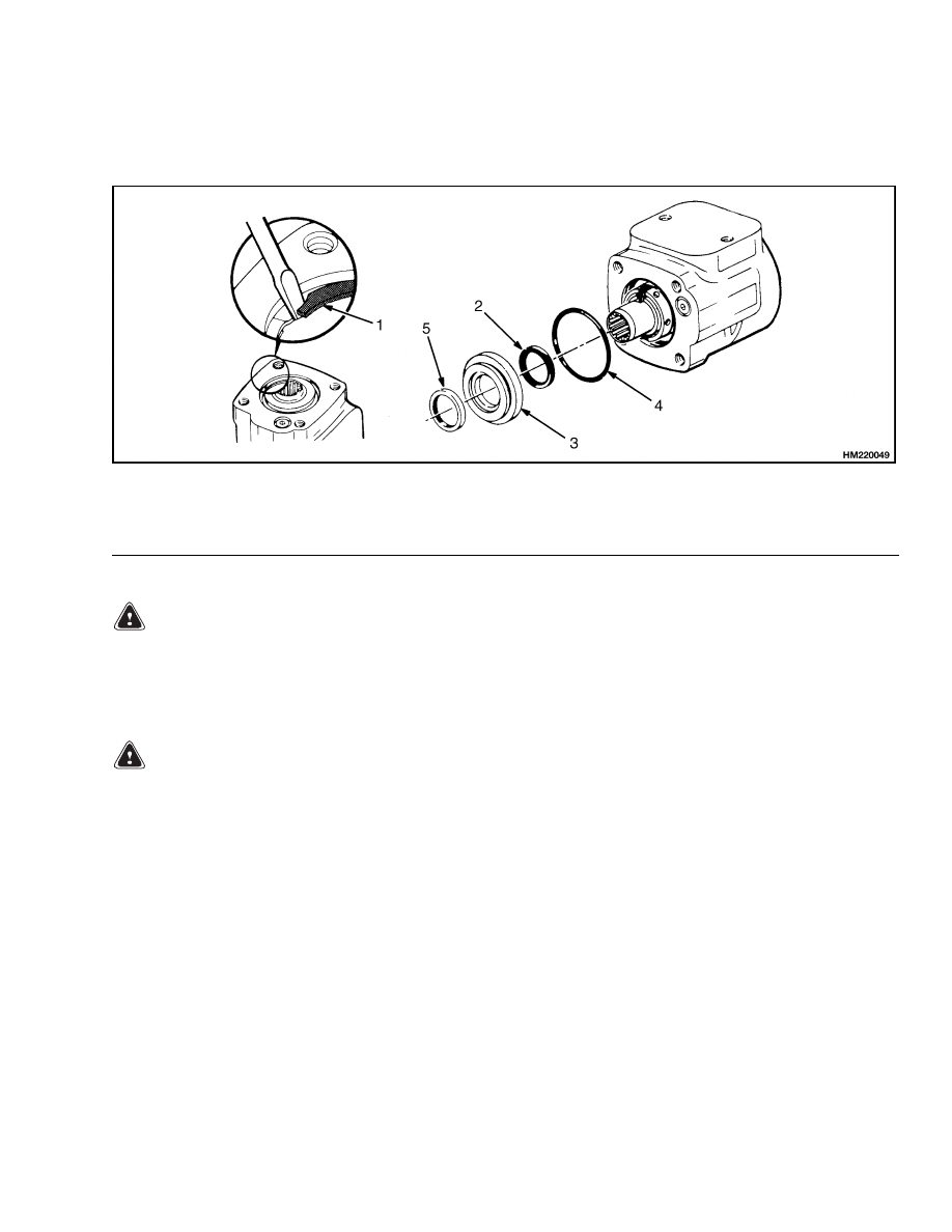
STEP 6.
When installed, remove the snap ring, bushing, O-ring, and seal ring. Remove the oil seal from the bushing or
housing.
1.
SNAP RING
2.
SEAL
3.
BUSHING
4.
O-RING
5.
OIL SEAL
Clean
WARNING
Cleaning solvents can be flammable and toxic
and can cause skin irritation.
When using
cleaning solvents, always follow the solvent
manufacturer’s recommended safety precau-
tions.
WARNING
Compressed air can move particles so that they
cause injury to the user or to other personnel.
Make sure that the path of the compressed air
is away from all personnel.
Wear protective
goggles or a face shield to prevent injury to the
eyes.
Clean all the parts in solvent. Dry the parts with
compressed air. Do not dry the parts with a cloth.
Make sure all surfaces are free of scratches and sharp
edges.
11
Steering Wheel and Column Assembly Repair
1600 SRM 512
Assemble
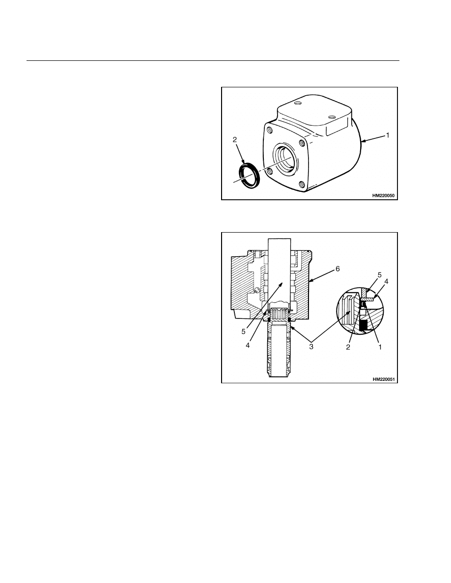
STEP 1.
Install the seal.
1.
HOUSING
2.
SEAL
STEP 2.
Put the spool on the workbench, then put the housing
onto the spool as shown. Install the guide ring with
the O-ring on the end of the spool. Put the thrust
washer on top of the guide ring and O-ring assem-
bly. See STEP 6. Use a socket or tube to push on
the washer and install the O-ring and guide ring in
the housing. Carefully remove the washer, tube, and
spool from the housing.
1.
O-RING
2.
GUIDE RING
3.
SPOOL
4.
WASHER
5.
TUBE
6.
HOUSING
12
1600 SRM 512
Steering Wheel and Column Assembly Repair
STEP 3.
Carefully assemble the spool and sleeve. Make sure
the spool rotates freely in the sleeve.
1.
SPOOL
2.
SLEEVE
STEP 4.
Assemble the neutral position springs, then push them into position in the spool. Make sure the flat springs
are installed to the outside of the curved springs. Install the center pin. Install the ring on the sleeve (over the
neutral position springs). The ring must turn freely on the sleeve.
1.
NEUTRAL POSITION SPRINGS (FLAT)
2.
NEUTRAL POSITION SPRINGS (CURVED)
3.
CENTER PIN
4.
SPOOL
5.
RING
13
Steering Wheel and Column Assembly Repair
1600 SRM 512
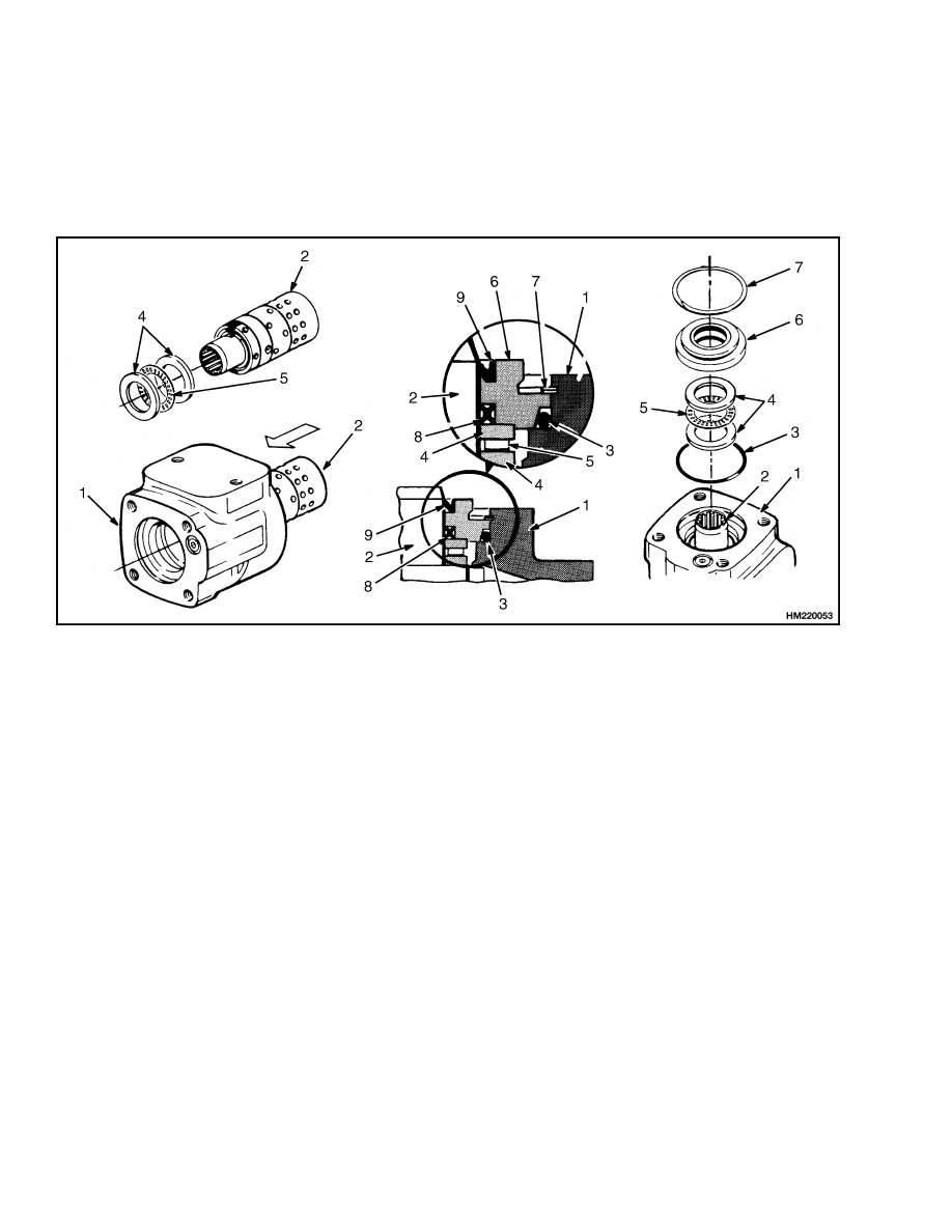
STEP 5.
When the control unit has the type of bearing arrangement shown here, use the following procedures:
Install the thrust washers and thrust bearing on the spool. Carefully install the spool and sleeve assembly in
the housing. Install the dust seal in the bushing. Install the bushing, seal, and O-ring in the housing. Use the
snap ring to hold the bushing in position. Make sure the sleeve rotates freely in the housing.
1.
HOUSING
2.
SPOOL AND SLEEVE ASSEMBLY
3.
O-RING
4.
THRUST WASHER
5.
THRUST BEARING
6.
BUSHING
7.
SNAP RING
8.
SEAL
9.
DUST SEAL
14
1600 SRM 512
Steering Wheel and Column Assembly Repair
STEP 6.
Install the thrust washers and thrust bearing on the
spool. Make sure the chamfer on the inner thrust
washer is next to the sleeve. Install the spool and
sleeve assembly in the housing.
Carefully rotate
the spool and sleeve assembly during installation to
make sure the spool fits correctly in the seal installed
in STEP 1. Make sure the center pin in the spool
and sleeve assembly is horizontal.
1.
HOUSING
2.
SPOOL AND SLEEVE ASSEMBLY
3.
THRUST WASHER
4.
THRUST BEARING
5.
SPOOL
6.
SLEEVE
7.
PIN
15
Steering Wheel and Column Assembly Repair
1600 SRM 512
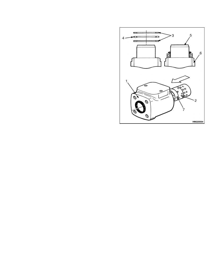
STEP 7.
When the check valve is at the end of the housing as
shown here, install the check ball and sleeve. Make
sure the sleeve is even with or below the surface of the
housing. Lubricate the O-ring and install the O-ring
and port plate. Align the holes in the port plate with
the holes in the housing.
1.
HOUSING
2.
O-RING
3.
PORT PLATE
16
1600 SRM 512
Steering Wheel and Column Assembly Repair
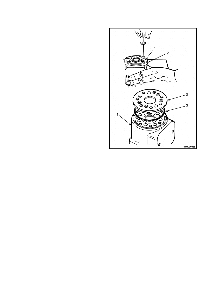
STEP 8.
Install the center shaft so that it engages with the center pin in the spool and sleeve assembly. Make sure the
center pin is still parallel to the flat surface of the housing. Install the rotor on the center shaft. Make sure
that a valley in the rotor aligns with the slot (center pin) in the center shaft. Install the O-ring and stator.
Make sure to align the marks made during disassembly.
1.
CENTER SHAFT
2.
CENTER PIN
3.
ROTOR
4.
STATOR
5.
O-RING
17
Steering Wheel and Column Assembly Repair
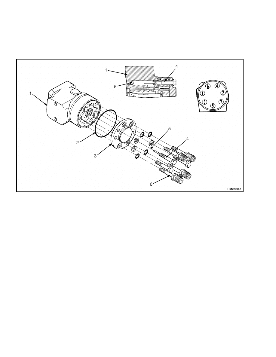
1600 SRM 512
STEP 9.
Install the O-ring and the cover. If removed during disassembly, install the spacer (not shown). Tighten the
capscrews for the cover in the sequence shown to 17 N•m (150 lbf in), then tighten them to 30 N•m (266 lbf in).
Make sure the capscrew with the pin fits in the hole for the check ball.
1.
HOUSING
2.
O-RING
3.
COVER
4.
CAPSCREW
5.
CHECK BALL
6.
SPECIAL FITTING
18

1600 SRM 512
Steering Wheel and Column Assembly Repair
Install
Install the steering control unit and column assembly on the bracket as follows:
STEP 1.
Install the steering column and steering control unit
in the bracket. Install the steering wheel and nut.
Tighten the nut to 40 to 54 N•m (30 to 40 lbf ft). Con-
nect the wire at the horn button and install the horn
button.
1.
HORN BUTTON
2.
NUT
3.
STEERING WHEEL
4.
CAPSCREW
5.
LOCKWASHER
6.
WASHER
7.
STEERING COLUMN
8.
BRACKET
9.
STEERING CONTROL UNIT
19
Steering Wheel and Column Assembly Repair
1600 SRM 512
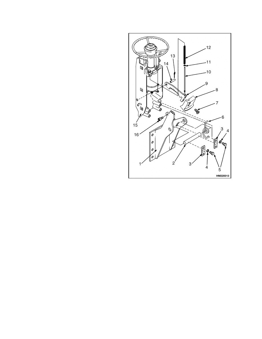
STEP 2.
Install the mount on the cowl. Install the latch on
the bracket, using the pin and cotter pin. Install the
bracket on the mount with the pivot shaft and spring.
Install the plates and capscrews that hold the bracket
to the shaft. Install the spring, washer, and rod for
the latch. Install the knob on the latch. Install the
socket head screw and nut.
1.
MOUNT
2.
PIVOT SHAFT
3.
PLATE
4.
CAPSCREW
5.
LOCKWASHER
6.
SPRING
7.
SCREW
8.
KNOB
9.
LATCH
10. ROD
11. WASHER
12. SPRING
13. COTTER PIN
14. PIN
15. BRACKET
16. SOCKET HEAD SCREW
20
1600 SRM 512
Steering Wheel and Column Assembly Repair
WARNING
The hydraulic hoses MUST be connected to the correct ports, or the steering system will not oper-
ate as expected. This unexpected operation can cause damage or personal injury. Make sure the
hoses are identified and connected correctly.
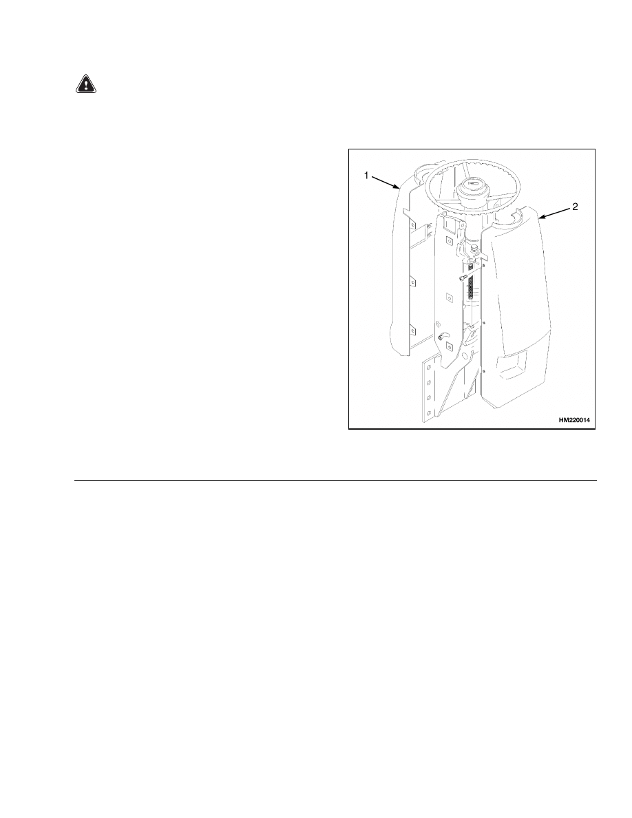
STEP 3.
Install the instrument cluster on the front cover.
See the section Instrument Cluster 2200 SRM
514 to make the necessary wiring connections
for the S/H2.00-3.20XM (S/H40-65XM) lift truck
models. See the section Electrical System 2200
SRM 560 to make the necessary wiring connections
for the J2.00-3.20XM (J40-65XM), E2.00-3.20XM
(E45-65XM),
J1.60-2.00XMT
(J30-40XMT),
and
N30XMH lift trucks.
Install the covers on the
bracket. Connect the hydraulic lines to the steering
control unit.
1.
FRONT COVER
2.
REAR COVER
STEERING COLUMN ASSEMBLY, INSTALL
1.
Install the steering column on the cowl mounts.
Lubricate the pivots with multipurpose grease
and install the capscrews into the housing.
2.
Fasten the two halves of the mount bracket to the
steering control unit. Make sure to install the
bracket for the activator assembly. Install the
steering control unit assembly into the steering
column. Make sure to install the horn switch and
the switch bracket as well as the two wire clamps
on the same mount capscrews.
3.
Install the bearing on the steering shaft. The
seal of the bearing must be toward the steering
wheel. Install the snap ring in the groove on the
steering shaft.
4.
Put the steering shaft through the opening for
the bearing in the steering housing. Install the
pin that holds the plastic tube and flange for the
horn switch. Install the plastic tube, the plas-
tic flange, and the spring onto the steering shaft.
Push the steering shaft into the splines or align
the keyway of the steering control unit. Install
the snap ring that holds the bearing in the steer-
ing housing.
5.
Install the steering wheel. Install the large hex
nut onto the steering shaft. Install the push rod
and adjuster spool into the steering shaft. Install
the horn cover.
21
Troubleshooting
1600 SRM 512
WARNING
The hydraulic hoses MUST be connected to
the correct ports and fittings, or the steering
system will not operate as expected.
This
unexpected operation can cause damage or
personal injury. Make sure the hoses are iden-
tified and connected correctly.
6.
Connect the hydraulic hoses to the steering con-
trol unit, the cowl, the control valve, or the steer-
ing pump as removed during removal. Make sure
each hydraulic hose is connected to the correct
ports or fittings as identified during removal.
7.
Connect the wire connectors at the bottom of the
steering column. Install the access cover on the
steering column.
WARNING
After making repairs, do not extend the hands
or arms through the center of the steering
wheel. If the control unit was not assembled
correctly or the hoses not connected correctly,
it can rotate with a strong force and cause
serious injury. If this occurs, disassemble the
control unit and correct the problem.
8.
Connect the battery and operate the steering sys-
tem to check for correct operation and leaks.
System Air Removal
REMOVE
Air can enter the system when a hydraulic line is dis-
connected. If the operation is rough, operate the sys-
tem and rotate the steering wheel from stop to stop
several times in each direction. The air will be re-
moved without disconnecting any lines. If the opera-
tion is still rough, check if air is entering the system
at a loose fitting.
Troubleshooting
PROBLEM
POSSIBLE CAUSE
PROCEDURE OR ACTION
The steering wheels do not
move
when
the
steering
wheel is turned.
The oil level is low or there is no oil
in the tank.
Fill tank to the correct level. Check
for leaks.
The steering control unit is dam-
aged.
Repair or install new control unit.
No oil flow from the steering control
unit to the steering cylinder.
Repair or install new components.
Check for leaks.
The sleeve and spool in the control
unit will not move.
Install new components.
Hydraulic hoses not connected or
have damage.
Check for leaks.
Tighten connec-
tions.
Install new components as
necessary.
22

1600 SRM 512
Troubleshooting
PROBLEM
POSSIBLE CAUSE
PROCEDURE OR ACTION
Slow or difficult steering.
Relief valve for the steering system
is not adjusted correctly.
Adjust or install new relief valve.
Low oil pressure from the hydraulic
pump.
Check for restrictions.
See Trou-
bleshooting Hydraulic System.
Seal in the steering cylinder has a
leak.
Repair cylinder. Install new seal or
new cylinder.
Hydraulic lines are too small or have
restrictions.
Remove restrictions. Install larger or
new hydraulic lines.
Steering control unit is worn, not as-
sembled correctly, or has damage.
Repair or install new control unit.
Steering wheel turns the
tires in the wrong direction.
The hydraulic lines are not con-
nected correctly at the steering
cylinder or at the steering control
unit.
Connect lines correctly. Remove air
from the system.
Steering
function
contin-
ues after the steering wheel
stops.
The steering control unit is assem-
bled wrong or has damage.
Repair or install new control unit.
The steering operation is not
smooth.
The oil level in the tank is low.
Fill tank. Check for leaks.
Air was not removed after repair to
the hydraulic system.
Remove air from the system.
The steering control unit is assem-
bled wrong or has damage.
Repair or install new control unit.
The hydraulic pump has a leak at the
inlet.
Fix leaks. Remove air from the sys-
tem.
23

NOTES
____________________________________________________________
____________________________________________________________
____________________________________________________________
____________________________________________________________
____________________________________________________________
____________________________________________________________
____________________________________________________________
____________________________________________________________
____________________________________________________________
____________________________________________________________
____________________________________________________________
____________________________________________________________
____________________________________________________________
____________________________________________________________
____________________________________________________________
____________________________________________________________
____________________________________________________________
____________________________________________________________
____________________________________________________________
____________________________________________________________
24


TECHNICAL PUBLICATIONS
1600 SRM 512
8/03 (11/95)(8/95)(3/95)(8/94)(8/93)(4/93) Printed in U.S.A.
Document Outline
- toc
Wyszukiwarka
Podobne podstrony:
897641 8000SRM0561 (08 2003) US EN
897493 1600SRM0512 (11 1995) UK EN
1466241 1600SRM0732 (10 2003) UK EN
897556 1400SRM0542 (12 2003) US EN
897993 1600SRM0671 (09 2003) UK EN
897392 1600SRM0451 (09 2003) UK EN
1466235 1600SRM0733 (09 2003) UK EN
1470230 1600SRM0786 (11 2003) UK EN
910076 1600SRM0054 (10 2003) UK EN
1494140 1600SRM0936 (09 2003) UK EN
897493 1600SRM0512 (11 1995) UK EN
więcej podobnych podstron