Trihal
instructions
for installation
and maintenance
contents
receipt and handling
1
installation
4
HV and LV connections
10
Z thermal protection
15
T-935 thermal protection
29
commissioning
41
maintenance and after sales services
46
check-list before commissioning
47
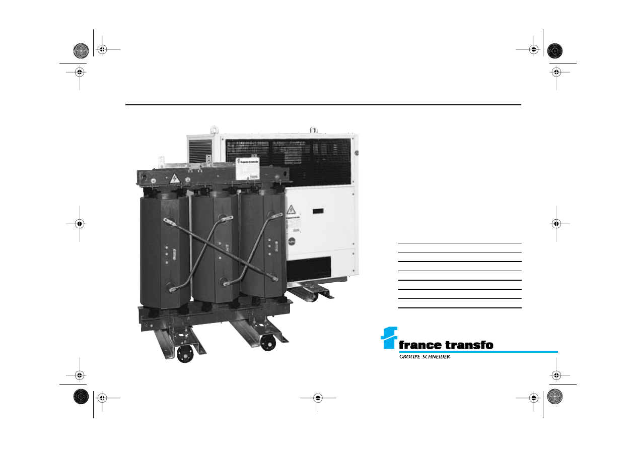
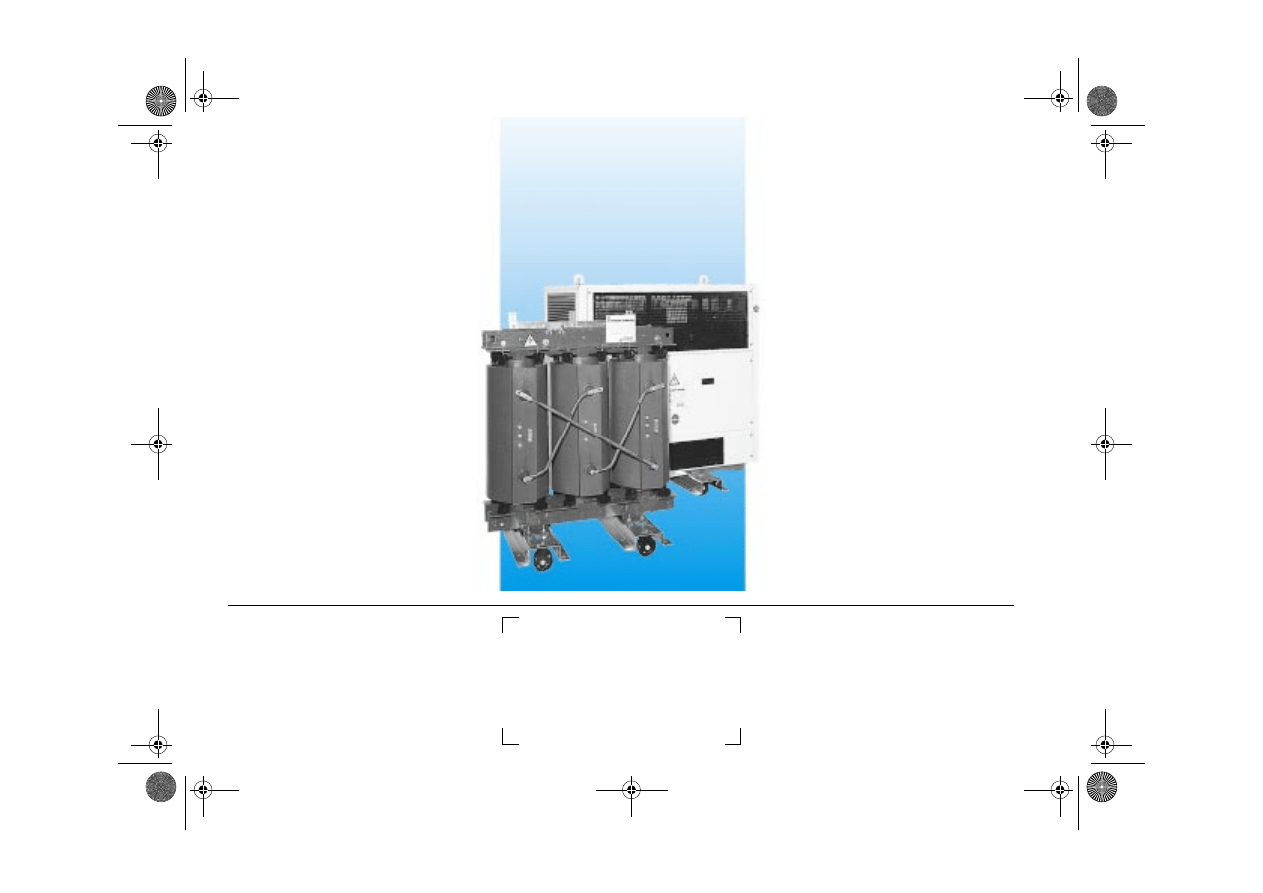
cast resin transformer
GEa 215000 c/couv Page 1 Mercredi, 17. mars 1999 4:03 16
Trihal
1
France Transfo
preliminary checks
On receipt, ensure that the transformer has not been damaged during transport (LV
busbars or HV connection terminals bent, broken insulators, damaged windings, wet
transformer, damaged cover, contamination by foreign bodies, etc.), and check that
any ordered accessories have been included in the delivery (rollers, electronic con-
verter, etc.).
Should the device have been damaged:
n
take delivery subject to reservations which should be indicated to the transporter
and confirm this by registered letter within three days.
n
Write a report and send it without delay to your supplier (France Transfo or retailer
as appropriate).
warning
This instruction manual is designed
to apply to standard range Trihal
transformers, as defined in the
France Transfo catalogues. For
special Trihal transformers, i.e.
those produced in accordance
with a special requirement or a
customers specification, certain
statements and recommendations
may not be applicable (particular
the paragraphs dealing with the
IP31 enclosure, the HV and LV
connections, the thermal protec-
tion, etc.)
If you are in any doubt, please con-
tact the after sales department.
tel.: (33) 3 87 70 57 57
fax: (33) 3 87 70 56 21
receipt and handling
GEa 215000 c 1/48 Page 1 Mercredi, 17. mars 1999 4:02 16
2
Trihal
France Transfo
storage
The Trihal transformer must be protected in storage from water and protected from
dust generating work (masonry, sanding, etc.).
The Trihal transformer is delivered in a plastic cover, this cover must be kept over the
equipment whilst it is in storage.
The Trihal transformer can be stored at a temperature down to – 25°C.
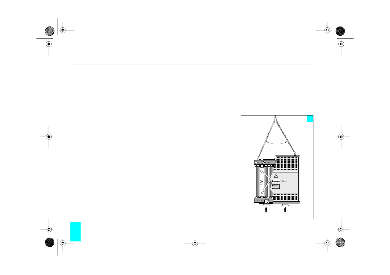
handling
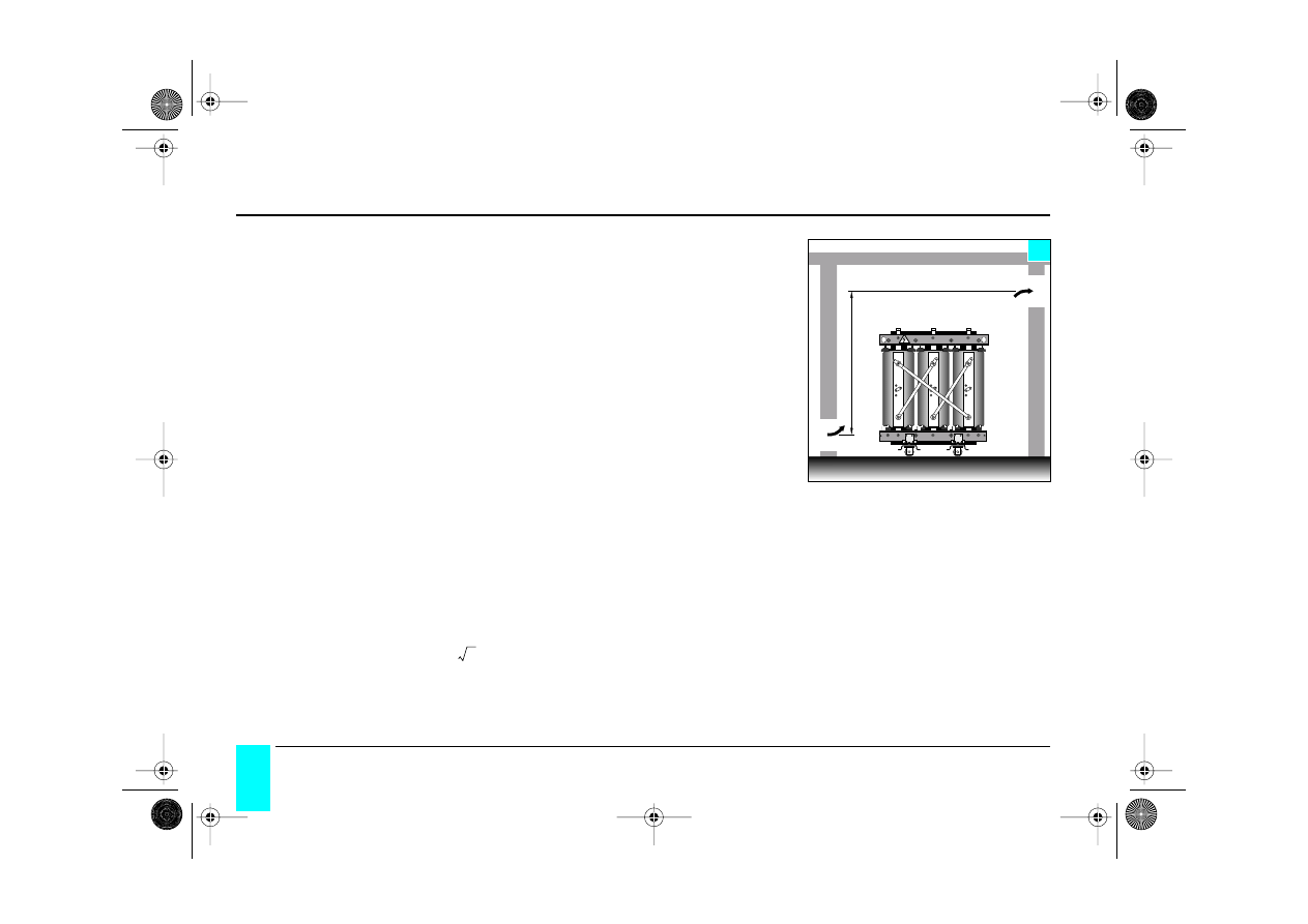
The transformers are equipped with specific handling attachments.
n
Iifting with slings (figure 1).
For a transformer without an enclosure lifting is carrieed out using the 4 lifting lugs
and for a transformer with an enclosure using 2 lifting lugs. The slings should not
form an inside angle greater than 60°.
n
Iifting with a fork lift truck (figure 1).
Remove the rollers and insert the forks in the base channels.
n
towing
Towing the transformer, with or without enclosure, must be performed from the
underbase. Holes of 27 mm diameter are provided for this purpose on all sides of the
underbase. Towing can only be carried out in two directions:
parallel to the underbase axis and perpendicular to that axis.
n
°
216 452
Groupe Merlin Gerin · Usine de Maizières-lès-Metz (Moselle) France
nº 216540
60°
maxi
1
fork lift truck lifting points
receipt and handling
GEa 215000 c 1/48 Page 2 Mercredi, 17. mars 1999 4:02 16
Trihal
3
France Transfo
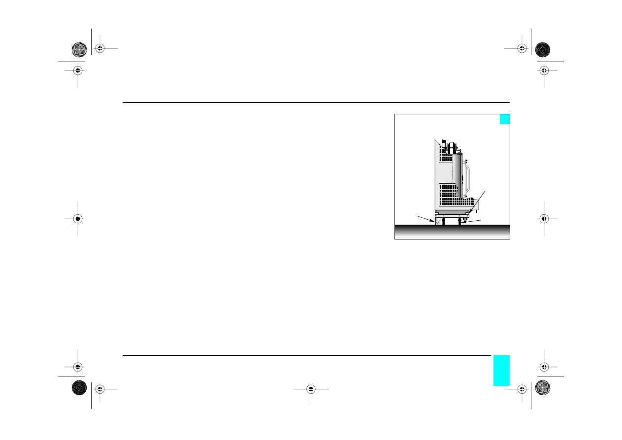
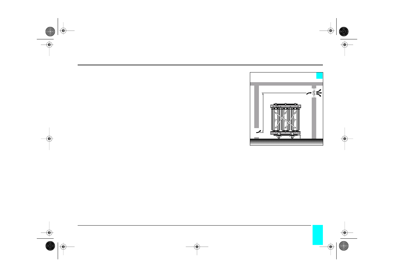
n
fitting the rollers
▫
either by lifting with slings (figure 1);
▫
or by lifting with a fork lift truck (figures 1 and 2).
In this case position the lifting forks in Trihal’s underbase channels.
Place timbers of a greater height than the rollers under the channels and lower the
transformer onto them.
Position the jacks and remove the timbers.
Attach the rollers in the desired position (two bi-directional rollers).
Remove the jacks and allow the Trihal to rest on its rollers.
Note
: Trihal transformers are generally wedged during transport using timbers that
are attached to the vehicle’s base. It is thus essential to remove these timbers
before lifting the transformer.
timbers
jacks
rollers
2
receipt and handling
GEa 215000 c 1/48 Page 3 Mercredi, 17. mars 1999 4:02 16
4
Trihal
France Transfo
general information
Due to the absence of any liquid dielectric, there is no risk of liquid “cold” (spillage)
and “hot” (combustion) pollution, and due to the qualities of Trihal transformers, no
fire precautions are necessary.
n
The Trihal transformer should not be installed in a flood hazard area.
n
It should not be installed at an altitude above 1000 metres, unless the altitude is
specified at the time of ordering.
n
The transformer is designed to operate at rated power in the ambient temperatu-
res detailed below.
n
The ambient temperature of the substation, where the transformer is installed,
should be within the following limits:
- minimum temperature: – 25°C;
- maximum temperature: + 40°C (unless a special request is made for a specially
designed transformer to operate in higher ambient temperatures).
installation
GEa 215000 c 1/48 Page 4 Mercredi, 17. mars 1999 4:02 16

Trihal
5
France Transfo
n
Standard transformers are dimensioned in accordance with IEC 76 for an ambient
temperature of:
• maximum: . . . . . . 40°C
• daily average: . . . 30°C
• yearly average: . . 20°C
Generally speaking the installation must be in compliance with IEC standard 71-1,
2 and 3 concerning insulation co-ordination.
Note : In order to ensure correct ventilation of the transformer, it should always
be mounted on its rollers or raised to a height equal to that of the rollers.
installation
GEa 215000 c 1/48 Page 5 Mercredi, 17. mars 1999 4:02 16
6
Trihal
France Transfo
determination of the height and
area of the ventilatio grills
In the general case of natural cooling (AN), ventilation of the substation or the enclo-
sure by natural convection, such ventilation must dissipate the heat generated by the
transformer’s total losses in operation.
Appropriate ventilation will consist of a fresh air intake opening of S cross-section at
the bottom of the substation and an air outlet of cross-section S’ located above on
the opposite wall at height H metres above the air intake opening.
It should be noted that restricted air circulation reduces the transformer’s available
power.
equation for calculating ventilation
P = the sum of the no-load and load losses of the transformer expressed in kW at
120°C as well as the losses emitted from all the equipement present in the pre-
mises.
S = the area of the air intake opening (allow for mesh factor) expressed in square
metres.
S’ = area of the air outlet opening (allow for mesh factor) expressed in square metres.
H = height difference between the two openings expressed in metres.
and
This formula is valid for an average annual room temperature of 20°C and an altitude
of 1000 m maximum.
H
S
S’
3
S
0 18P
,
H
---------------
=
S
′
1 10
S
×
,
=
installation
GEa 215000 c 1/48 Page 6 Mercredi, 17. mars 1999 4:02 16
Trihal
7
France Transfo
forced ventilation of the premises
This is required in the case of small or badly ventilated premises, with an annual ave-
rage temperature greater than 20°C, or in the instance of frequent overloading of the
transformer.
So as not to disturb the natural convection in the premises, an extractor fan dischar-
ging air outside will be installed in the outlet hole located in the top part of the unit; it
can be thermostat controlled.
Recommended flowrate (m
3
/second) at 20°C = 0,10 P
P = total losses to be removed, in kW, emitted by all the installed equipment.
H
S
S’
H mini
= 160 mm
4
installation
GEa 215000 c 1/48 Page 7 Mercredi, 17. mars 1999 4:02 16
8
Trihal
France Transfo
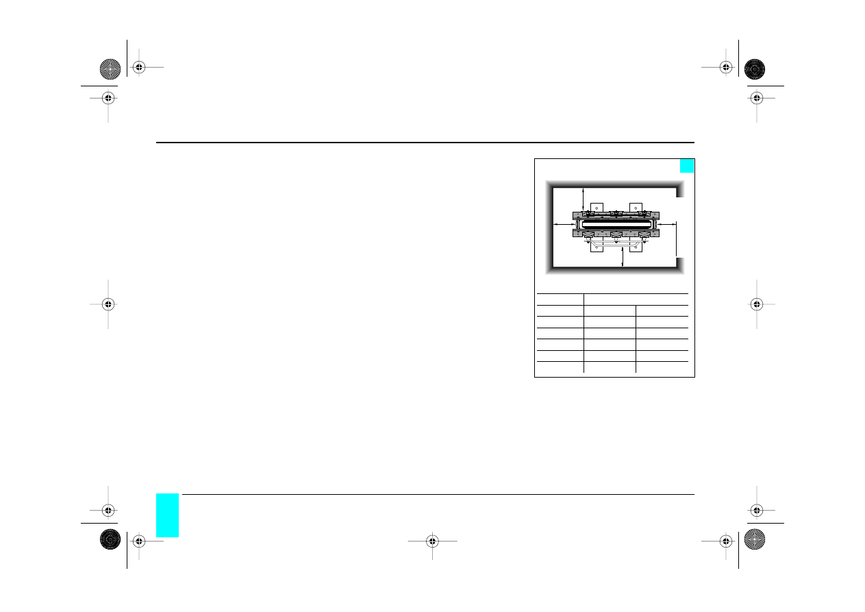
Trihal transformer without enclosure (IP 00)
As the IP 00 protection index indicates, this transformer has no protection against
touching or direct contact.
In no instance should the surface of the resin be touched when the transformer is
live, even if the transformer is equipped with plug-in connectors.
When installing Trihal in a secure substation:
n
eliminate risks of water dropping on the transformer (e.g. condensation from ove-
rhead pipes, etc.);
n
maintain minimum clearance distances to the walls in accordance with the insula-
tion voltages given in figure 5, whilst providing sufficient space to access the pri-
mary voltage tapping points. Should these distances not be possible to achieve
please contact us.
n
ensure that the substation ventilation is sufficient to dissipate all losses.
(1) do not take account of access to the voltage variation tapping links.
X
X
X (1)
X
5
insulation
dimension X (mm)
(kW)
full wall
ventillation grill
7,2
90
300
12
120
300
17,5
220
300
24
220
300
36
320
320
installation
GEa 215000 c 1/48 Page 8 Mercredi, 17. mars 1999 4:02 16
Trihal
9
France Transfo
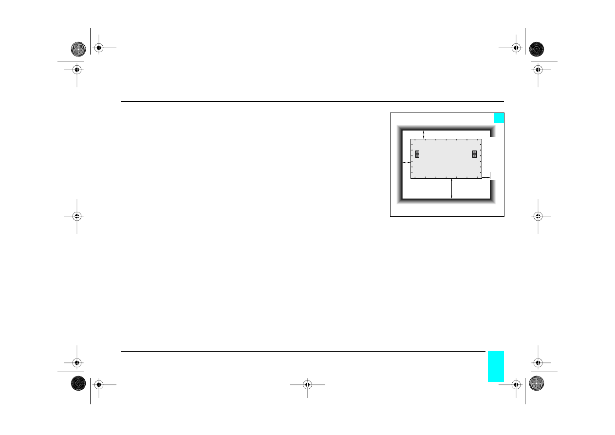
Trihal transformer with IP 31 metal enclosure
The integral, IP 31 metal enclosure is of indoor type and is not able to be installed as
it stands outdoors. Its installation requires no particular precautions other than those
detailed in the general installation instructions with the additional consideration of
a
minimum clearance requirement of 200 mm (500 mm on the HV side) between
the exterior of the enclosure and the walls of the substation
so as not to obstruct
the enclosures ventilation grills and to allow adequate cooling (figure 6), whilst provi-
ding sufficient space to access the primary voltage tapping points.
Ventilation of the substation should be studied so as to fully dissipate all of the heat
generated through losses the total losses emitted by all the equipement (without
exceeding the limits defined on page 5).
Recall
: the Trihal transformer must not be installed in a flood hazard area.
Warning
: the standard metal enclosure for Trihal transformers is IP 31, except for the
underbase which is IP 21.
(2) 200 mm minimum allowed for access to the voltage variation tapping links.
200 mm
500 mm (2)
200 mm
200 mm
LV
HV
6
installation
GEa 215000 c 1/48 Page 9 Mercredi, 17. mars 1999 4:02 16
10
Trihal
France Transfo
Trihal transformer without metal enclosure (IP 00)
Warning
: the resin coating, does not guarantee protection against touching or
against direct contact when the transformer is energized.
n
standard HV and LV connections (figure 7)
In all cases, the cables or busbars must be supported to avoid mechanical stress on
the HV or LV terminals.
The outgoing (or incoming) LV connections can be made from the top or the bottom
(see figure 7).
The outgoing (or incoming) HV connections must be made to the top of the delta
connection bars.
It is possible to connect to the HV from below using a spacer (the spacer will not be
supplied by France Transfo).
Important: the distance between the HV cables, the LV cables or busbars, the
neutral and the surface of the HV winding must be at least 120 mm except on
the flat front part where the minimum distance will be that given by the HV ter-
minals.
7
cable support
LV
n
HV
HV
spacer
120
mini
120
mini
HV and LV connections
GEa 215000 c 1/48 Page 10 Mercredi, 17. mars 1999 4:02 16
Trihal
11
France Transfo
n
HV connections with plug-in connectors (figure 8)
In any case, the cables or busbars must be supported to avoid mechanical stress on
the fixed parts of the plug-in connectors (HN 52 S 61) and the transformer’s LV out-
put terminals.
The outgoing (or incoming) LV connections can be made from above or below (see
figure 8).
The outgoing (or incoming) HV plug-in connectors (HN 52 S 61) must be made from
above on the HV side (see figure 8).
On request, as an option, a key-less locking system for the plug-in connectors can
be installed on the fixed parts (HN 52 S 61).
In this configuration, the installation of plug-in connectors does not provide
safety against direct contacts
, the resin coating does not guarantee protection
against touching or direct contact when the transformer is live.
Important: the distance between the HV cables, the LV cables or busbars, the
neutral and the surface of the HV winding must be at least 120 mm except on
the flat front part where the minimum distance will be 120 mm from the HV ter-
minals.
8
cable support
LV
n
HV
120
mini
120
mini
HV and LV connections
GEa 215000 c 1/48 Page 11 Mercredi, 17. mars 1999 4:02 16
12
Trihal
France Transfo
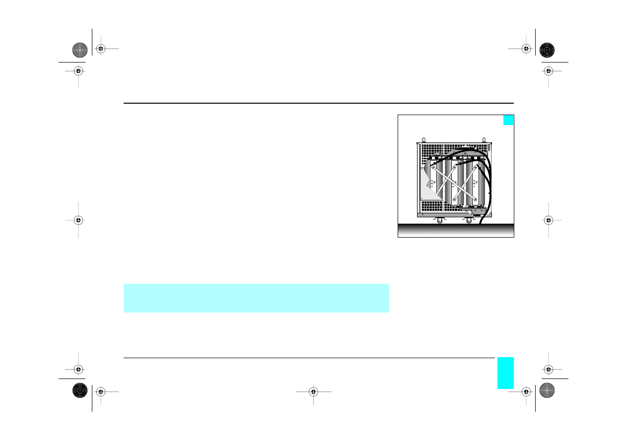
Trihal transformer with IP 31 metal enclosure
The IP 31 metal enclosure must under no circumstances support loads other than
those of the transformer’ HV supply cables. For any modifications to the enclosure,
please consult us.
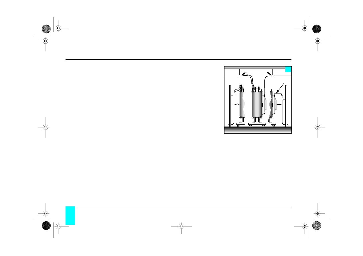
n
standard HV and LV connections (figure 9)
In all cases, the cables or busbars must be supported to avoid mechanical stress on
the transformer’s HV or LV terminals.
The outgoing (or incoming) LV connections must be made upwards from the termi-
nals under the enclosure cover (see figure 9).
The LV cables should never pass
between the HV coils and the enclosure.
The outgoing (or incoming) HV connections must be made to the top of the delta
connection bars.
The HV cables should pass upwards from the terminals under the enclosure cover,
but they also have the possibility of entry from below (figure 10).
9
cable support
cable support
LV
n
HV
HV and LV connections
GEa 215000 c 1/48 Page 12 Mercredi, 17. mars 1999 4:02 16
Trihal
13
France Transfo
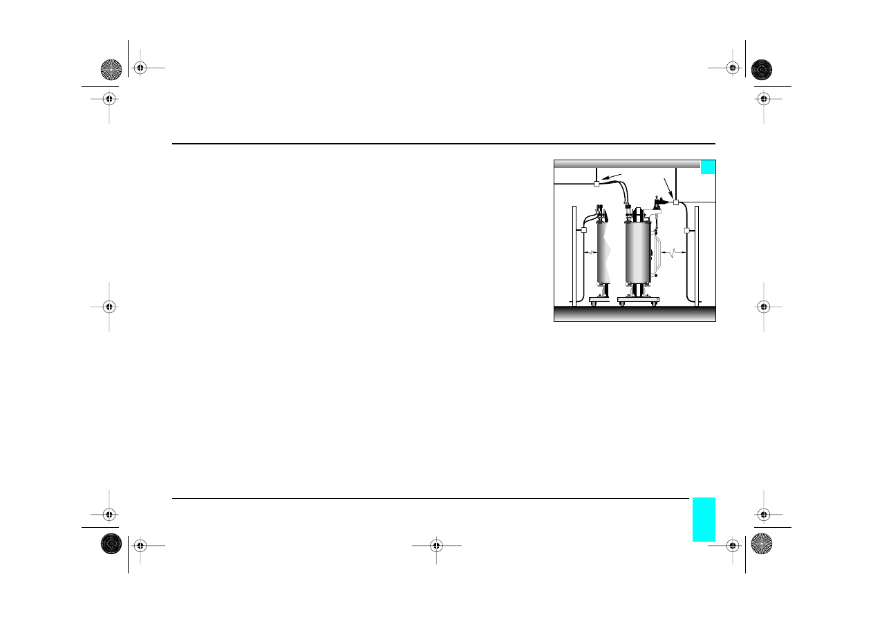
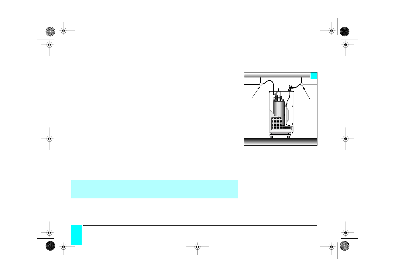
n
HV connections from below (figure 10)
In all cases, the cables or busbars must be supported to avoid mechanical stress on
the transformer’s HV or LV terminals.
The outgoing (or incoming) LV connections must be made upwards from the termi-
nals under the enclosure cover (see figure 10).
The LV cables should never pass
between the HV coils and the enclosure.
The outgoing (or incoming) HV connections must be made to the top of the delta
connections bars.
A remove flap door located on the bottom right of the enclosure’s HV side allows the
HV cables to be connected from below. The HV cables must be fastened inside the
enclosure on the side panel, and they should at no time be at less than 120 mm from
the HV coils (except on the flat front part where the minimum distance will be that of
the HV terminals).
For cables in cable ducts, allow a depth sufficient to accomodate the cable’s mini-
mum bending radius.
N.B.
: the standard Trihal enclosure is IP 31, except for the underbase which is IP 21.
It is necessary to verify conformity with the IP 31 protection index after having
drilled the aluminium cover plates provided for this purpose for the HV, LV and
other connections.
10
HV
HV and LV connections
GEa 215000 c 1/48 Page 13 Mercredi, 17. mars 1999 4:02 16
14
Trihal
France Transfo
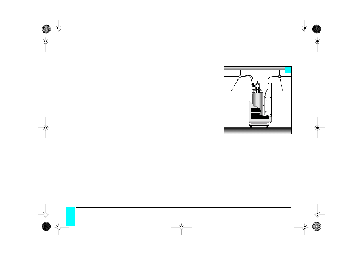
n
HV connections with plug-in connectors (figure 11)
In all cases, the cables or busbars must be supported to avoid mechanical stress on
the fixed parts of the plug-in connectors (HN 52 S 61) and the transformer’s termi-
nals.
The outgoing (or incoming) LV connections must be made upwards from the termi-
nals under the enclosure cover (see figure 11).
The LV cables should never pass
between the HV coils and the enclosure.
The outgoing (or incoming) HV plug-in connectors (HN 52 S 61) are made on the
enclosure cover on the HV side.
An optional, a key-less locking system for the plug-in connectors can be installed on
the enclosure cover.
N.B.
: the standard Trihal enclosure is IP 31 except for the underbase which is IP 21.
11
cable support
cable support
HV
LV
It is necessary to verify conformity with the IP 31 index after having drilled
the cover plates provided for this purpose for the HV, LV and other connec-
tions.
HV and LV connections
GEa 215000 c 1/48 Page 14 Mercredi, 17. mars 1999 4:02 16

Trihal
29
France Transfo
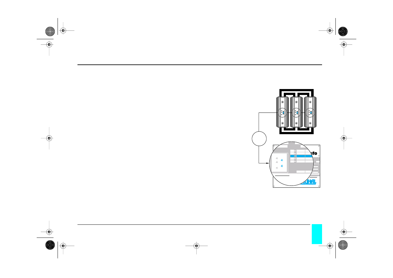
The second option for thermal protection of the windings is as follows.
The standard T-935 thermal protection module comprising:
n T-935 digital thermometer
n 1 terminal block
n 1 set of 3 PT 100 sensors.
The T-935 digital thermometer is supplied packed and attached to the transformer or
inside the enclosure.
Note: in the case of a different thermal protection defined and supplied by
France Transfo, please refer to the document supplied with the device.
T-935 thermal protection
GEa 215000 c 1/48 Page 29 Mercredi, 17. mars 1999 4:02 16

30
Trihal
France Transfo
technical specification
•
dimensions: 96x96 DIN
•
ABS self-exting. housing
•
produced in accordance to IMQ - VDE
- UL - CEE specs.
•
electrical connection with plug in ter-
minal board
•
IP 54 protection at the front
•
input from PT 100 sensors
•
3 channels protected against electrical
noises according to IEC 801 IV
•
self-diagnostic circuit
•
PT 100 length wiring compensation up
to 300 m. (10
Ω
max.)
•
digital PT 100 value linearization
•
magnetic and electric transient protec-
tion on input circ. and power supply
line according to IEC 801 IV
•
temperature monitoring from 0 up to
200°C
•
accuracy: ± 0.5% ± 1 digit
•
three alarm relays for L1-L2 fault con-
tact rating 5 Amp 250 V AC res.
•
universal power supply 24-220 V AC-
DC 50/60 Hz
•
operation temperature – 20°C to 60°C
maximum
•
maximum relative humidity 90 %
•
manual and automatic lamp test
•
temperature display, 14 mm High
•
alarm diagnosis
•
sensor diagnosis
•
alarm for defective sensor
•
incorrect programming automatic dis-
play
•
program data call (manual and auto
scanning)
•
automatic display of the channel with
the highest temp.
•
high temperature memory for each
channel
•
L1 and L2 alarm relay configuration
for: instant or maintained trip-relay
•
alarm reset
•
10 years data storage
•
alarm for incomplete program
•
easy programming of the functions.
T-935 thermal protection
GEa 215000 c 1/48 Page 30 Mercredi, 17. mars 1999 4:02 16

Trihal
31
France Transfo
options:
available at additional cost
A1
©
4th channel input from PT 100
cooling fan control (1st speed)
A2
©
4th channel input from PT 100
cooling fan control (2nd speed)
B1
©
output 4/20 mA or RS 232 or RS 485 (for the hottest channel)
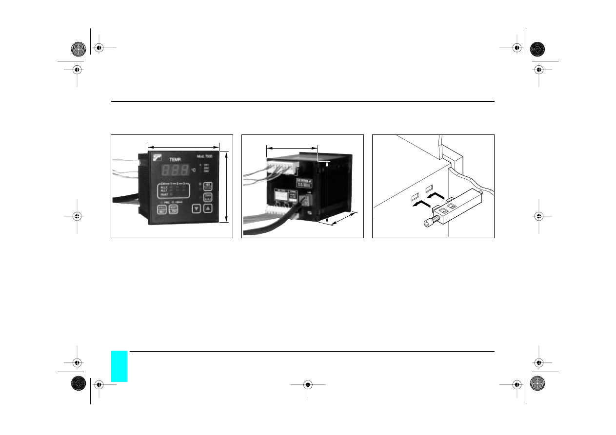
mounting
n mounting operture required in board 92 x 92 mm.
n locate device in hole and fix with screws provided.
T-935 thermal protection
GEa 215000 c 1/48 Page 31 Mercredi, 17. mars 1999 4:02 16
32
Trihal
France Transfo
overall dimensions of the Digital Thermometer
96 mm
96 mm
89 mm
91 mm
115 mm
T-935 thermal protection
GEa 215000 c 1/48 Page 32 Mercredi, 17. mars 1999 4:02 16
Trihal
33
France Transfo
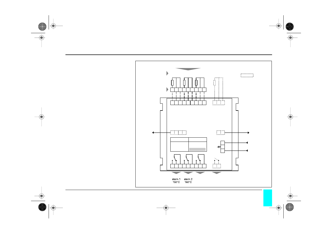
electrical connection
diagram (figure 1)
S.N. /DATE
POWER
24-220 V
AC / DC
1
2
3
4
70 71
72
73
13 14
15
16 17
18 19 20
21
22 23
24
50
51
5
6
7
8
9
10 11
42
41
40
1
2
3
4
5
6
7
8
9
A
CH1
B
CH2
C
CH3
CH4
T - 935
terminal board
on the transformer
transformer
LV coils
PT 100 sensors
on the transformer
OPTIONS
available at
extra cost
FAN 2
2nd ventilation
supply
24-220 V
AC - DC
ALL 1
ALL 2
FAULT
FAN 1
wiring
defect
detection
1st ventilation
output
4-20 mA
white
red
red
T-935 thermal protection
GEa 215000 c 1/48 Page 33 Mercredi, 17. mars 1999 4:02 16

34
Trihal
France Transfo
electrical connection
n remove unit from transformer or enclosure and connect wiring following
diagram 1.
n L1 and L2 relays are switched only when the pre-defined limits are reached.
n the FAULT relay is switched instantaneously when the unit is energized, and is
released by a fault in the sensors or in case of shut down.
power supply
The model T-935 is for Universal Power Supply. The voltage can be from 20 up to
220 V AC or DC, without respect of the polarity at the terminal board 40-42. Terminal
41 to be earthed.
Attention !
When the monitoring unit is powered at 220 V AC directly from the L.V. transfor-
mer line, you must protect the electronics with the protector module
PT-73-120 or 220, because high voltages transients can damage the instru-
ment.
T-935 thermal protection
GEa 215000 c 1/48 Page 34 Mercredi, 17. mars 1999 4:02 16

Trihal
35
France Transfo
PT 100 wiring connection
Each sensor has three wires, one is white and two red according to UNI 7937.
The figure 1 shows the bushings arrangement for the cables connection on the unit.
The channel 2 is always referred to the centre phase.
PT 100 signal connection wiring
All the cables for the PT 100 signal transport, they must be :
n separated from the HV cables,
n shielded and twisted (20 : 1),
n with area of 1 sq.mm minimum,
n the shield has to be grounded only in the panel, where the monitoring unit is pla-
ced.
n if mounted above transformer must be heat resistant.
n must not exceed 300 m. in length (10
Ω
).
T-935 thermal protection
GEa 215000 c 1/48 Page 35 Mercredi, 17. mars 1999 4:02 16

36
Trihal
France Transfo
programming of module T-935
When the voltage is ON:
n push the set button “PRG” for 4 seconds, until the led PROG light up,
- on the display “PR” appears and after 4 seconds is displayed the figures of L1
limit (pre-alarm) preprogrammed, all the L1 leds for the three channels, light up
- using “UP” and “DOWN” buttons, program the L1 value (temperature alarm 1)
- push PRG (momentary)
- on the display the temperature limit L2 appears, and all the leds of L2 for the
three channels light up
- procede as for L1
- push PRG; L1 must be lower than L2.
n if you decide to have the “latched trip-alarm” relays, push “UP” or “DOWN” but-
ton to have on the display “HLD”, the led “HOLD” light up.
n if you decide not to have the “latched trip-alarm” relays, push “UP” or “DOWN”
button to have on the display “---”.
- push PRG to end the programming cycle.
If options A1 or A2 (see page 29) are required, proceed as above for L1 to set the
starting and stopping temperatures of the forced cooling.
If options A1 or A2 (see page 29) are required, starting of cooling fans should be
set at 140°C and stop at 120°C.
During the programming cycle, the transformer is not under control. If, for any
reasons, the operator has not ended the program within the limit time of 60 seconds,
the program automatically reset at the values memorized in advance.
Remark : Since the transformer is to “F” thermal class, the T-935 thermometer
should be set with a maximum temperature of 150°C for the alarm 1 (L1) and
160°C for the alarm 2 (L2). France Transfo would not be held responsible for any
damage which may occur on the transformer if these temperatures are not res-
pected.
T-935 thermal protection
GEa 215000 c 1/48 Page 36 Mercredi, 17. mars 1999 4:02 16

Trihal
37
France Transfo
PT 100 sensor diagnosis
In case one of the PT 100 breaks, there will be an immediate closure of the FAULT
relay, the led L1, L2 of the channel flash. The FAULT led light will remain on.
Automatically on the display appears the channel monitored and the type of fault
which has occurred. The fault could be :
FCC if a sensor has a short circuit
FCO if a sensor is disconnected
From the information given by the display, the operator can easily locate the broken
sensor.
If one of the PT 100 is defective, there will be an FCD indication and flashing of the
channel’s led.
The FAULT relay switches to alert the operator by external horn or light.
Once the PT 100 is repaired or replaced, push RESET for 4 seconds, until on the dis-
play appears RST.
T-935 thermal protection
GEa 215000 c 1/48 Page 37 Mercredi, 17. mars 1999 4:02 16

38
Trihal
France Transfo
T° MAX checking
This function can display the T° MAX reached by the 3 channels, during the normal
running of the transformer, and the status of the alarm after the last RESET.
• To activate this function, push “T° MAX”; the led will light on.
• To visualize the T° MAX reached by the channels, push the buttons “AUM” and
“DIM”.
• To reset the memory of T° MAX and Alarm, push “Reset”.
Pushing “Reset” for 4 seconds, the 3 channels memories, the relays L1 and L2
will reset.
After 60 seconds approx. the T° MAX function will be automatically OFF.
temperature diagnosis
When a thermal sensor detects a temperature of 1°C higher to the values stated as
limit of the first alarm, after 4 seconds the L1 relay is actuated, and the led of the cor-
responding channel is switched on.
If the temperature goes on increasing until the limit of alarm nr 2, then the L2 relay is
actuated. If the temperature decreases to below the limit, the alarms stop. If the func-
tion “alarm latch” has been registered, the alarm will remain effective until the “Reset”
button is pushed.
T-935 thermal protection
GEa 215000 c 1/48 Page 38 Mercredi, 17. mars 1999 4:02 16

Trihal
39
France Transfo
“HOT SCAN” function
Pushing the button “HOT SCAN” automatically scans its channels.
When the led “hot” is illuminated, the display shows the channel with the highest
temperature.
If it is desired to display the temperature of the other channels, push “UP” and
“DOWN” for manual scanning.
check of the stored program
Push the button PRG.
If it is desired to change the temperature set points, push for 4 seconds the “PRG”
button; then procede with the programming procedure.
lamp test
Each year, check the leds by pushing on the “L Test” button.
T-935 thermal protection
GEa 215000 c 1/48 Page 39 Mercredi, 17. mars 1999 4:02 16

40
Trihal
France Transfo
“Reset” of L1 and L2 relays
for “alarm latching”
To reset the alarm relays (if the function “Hold” is registered), press the button
“Reset” for 4 seconds until the indication is displayed.
To control the values of registered temperatures L1 and L2.
Trip-alarm relays function
n When the function is ON, it is:
- “Hold” led light on.
- “Channels” leds light on.
n If channel is alarm for L1 or L2:
- “Hold” led is flashing and the relay L1 or L2 switches
- the L1 and / or L2 relays are energized even if the temperature of the PT 100
sensor is under the set point.
- the channel led is flashing.
n The reset of the alarms relays (L1 and L2):
- push the “Reset” button for 4 seconds; the relays deenergize, the led of
channel L1 / L2 goes out, the “Hold” led will remain illuminated.
The alarm will be memorized until the “Reset” of T° MAX/ALL.
T-935 thermal protection
GEa 215000 c 1/48 Page 40 Mercredi, 17. mars 1999 4:02 16
Trihal
41
France Transfo
n installation location
The location must be dry, finished and free from any possibility of water entry.
The Trihal transformer should not be installed in an area liable to be flooded.
The location should have sufficient ventilation to ensure that the total heat losses of
the installed transformers can be adequately dissipated. See pages 4 to 6.
n checking the condition after storage
If the Trihal transformer is found to be covered with dust, clean it as much as possible
with a vacuum cleaner then carefully blow with dry, degreased, compressed air or
nitrogen and thoroughly clean the insulators.
n Trihal transformers supplied with a plastic cover
To avoid contamination by foreign bodies (such as screws, nuts and washers, etc.),
the cover should remain in place whilst the transformer is being connected: to
gain access to the HV and LV connections, tear the cover around the tapping points,
this cover will be removed when the equipment is commissioned.
commissioning
GEa 215000 c 1/48 Page 41 Mercredi, 17. mars 1999 4:02 16

42
Trihal
France Transfo
n transformer supplied with integrated metal enclosure
The enclosure should not support loads other than the supply cables for the transfor-
mer, these cables should be independently supported to minimize the forces exerted
on the enclosure.
n transformer delivered with the original enclosure
The enclosure must never be subject to loads other than those of the transformer’s
MV supply cables.
Driling of the removable aluminium (amagnetic) plates at top and bottom, intended
for the passage of connecting cables must be performed with the plates removed
from the enclosure to avoid any swarf being introduced into the windings.
The installation within the enclosure of any swichgear or accessory, apart from cor-
rectly installed connections, is formally advised against and renders the warranty
invalid.
Installation of unauthorized equipment, other than HV and LV cables, will unvalidate
the guarantee.
For any modifications, attachments and mounting of non France Transfo accessories
on to the transformer, please fax our After Sales Service:
fax: (33) 3 87 70 56 21
See pages 12 to 14.
n HV and LV connections cables
In no case should the fixing points be made on the live part of the transformer.
The distance between the HV cables, the LV cables, or the LV bars and the sur-
face of the HV winding must be at least 120 mm, except on the flat front face
where the minimum clearance will be that given by the terminals.
See pages 10 to 14.
commissioning
GEa 215000 c 1/48 Page 42 Mercredi, 17. mars 1999 4:02 16
Trihal
43
France Transfo
n connections of HV connectors
Connections tightening torque on the HV terminal and the tapping link bars:
recall : 1m.kg = 0.98 daN.m
1N.m = 0.102 m.kg
Maximum force on the HV terminals: 500 N.
n connection of LV connectors
Connection tightening torque for the LV bars:
recall : 1m.kg = 0.98 daN.m
1N.m = 0.102 m.kg
bolts
M8
M10
M12
M14
tightening torque m/kg
1
2
3,5
6
bolts
M8
M10
M12
M14
M16
tightening torque m/kg
1,25
2,5
4,5
7
10
commissioning
GEa 215000 c 1/48 Page 43 Mercredi, 17. mars 1999 4:02 16

44
Trihal
France Transfo
n auxiliary wiring
Auxiliary wiring from the transformer (connection to sensor terminal block) should be
attached on rigid supports (without slack) and have sufficient clearance from live
parts. The minimum clearance to be respected is determined by the insulation vol-
tage indicated on the rating plate. In addition, in no case should attachments be
made to the live parts of the transformer.
n parallel operation
Verify the identity of the HV and LV voltages and the compatibility of characteristics
and especially of the vector groups and the impedance voltage.
Make sure that identical tappings are selected for transformers to be connected in
parallel.
commissioning
GEa 215000 c 1/48 Page 44 Mercredi, 17. mars 1999 4:02 16
Trihal
45
France Transfo
n checks before commissioning:
▫ remove the protective cover and check all the connections (arrangements, distan-
ces, tightening torque);
▫ check cable and busbars entries after connection through aluminium cover plates
to ensure IP rating has been maintained;
▫ in the same way, should there be an enclosure, check the earthing connections
after reassembling the covers;
▫ verify that the position identity of tapping links on the three phases are in
accordance with the diagrams on the rating plate;
▫ verify the transformer’s general state of cleanliness and carry out an insulation test
checking HV / earth and HV / LV using a 2500 V insulation tester (Megger).
The approximate value of the resistances are:
HV/earth
= 250 M
Ω
LV/earth
= 50 M
Ω
HV/LV
= 250 M
Ω
If the values measured are significantly below this, check that the transformer is not
moist. If it is, dry it with a rag and repeat the verification.
If it is not, please contact our After Sales Service:
tel.: (33) 3 87 70 57 57 - fax: (33) 3 87 70 56 21
=
transformateur enrobé
phase(s)
Hz
refroid.
Classe thermique F
Nº
année
Conforme à
et HD 464 S1:1988 / A3:1992
kVA
Ucc
%
couplage
IK
IP
basse tension
V
A
niveaux d’isolement
basse tension
haute tension
kV
masses
kg
kg
kg
sans enveloppe
de l’enveloppe
totale avec
enveloppe
Nota : raccordement HT
Classes HD 464-S1 : Comportement au feu
Climatique
Environnement
F 1
C 2
E 2
Effort limite à la traction sur les plages de raccordement : 500 N
Couple limite sur les vis de réglage et de raccordement : 20 mN
haute tension
relier
suivant le schéma ci-dessous
changement de tension
V
V
V
V
A
1 - 2
2 - 3
2 - 5
3 - 4
1
3
4
2
5
V
4 - 5
nº 220277
Groupe Schneider · Usine d’Ennery (Moselle) France
Nº
year
kVA
Impedance
%
high voltage
connect
coorthe drawing hereunder mentioned
position of tappings
2 - 3
2 - 5
3 - 4
1
3
4
2
5
4 - 5
Groupe Schneider · Usine
1 - 2
commissioning
GEa 215000 c 1/48 Page 45 Mercredi, 17. mars 1999 4:02 16
46
Trihal
France Transfo
maintenance
In normal use and environmental condi-
tions, once a year check the tightness of
the bolts on terminals and tapping links,
and vacuum clean and blow, those pla-
ces which are less accessible, with dry
compressed air or nitrogen.
The frequency of cleaning will depend on
environmental conditions.
In the case of greasy dust deposits, use
only cold degreasing product to clean
the resin surfaces (e.g. DARTOLINE SRB
71 or HAKU SRB 71).
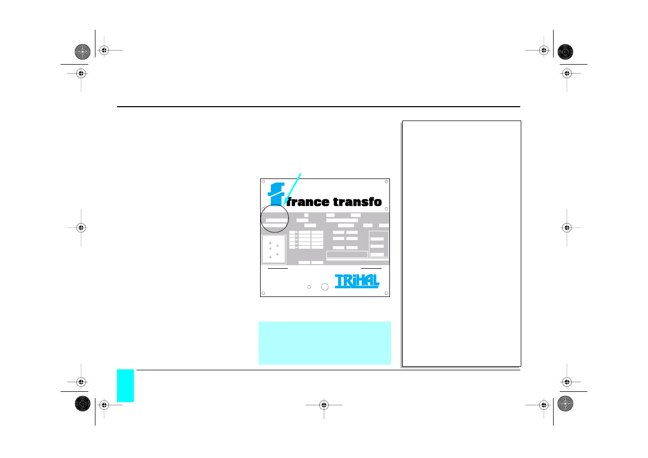
after sales service
For any information or replacement parts
it is essential to quote the main characte-
ristics on the rating plate and especially
the transformer’s serial number.
technical memo
(to be read from the rating plate)
N°
:___________________
Year
:___________________
Power
:___________________ kVA
Frequency
:___________________ Hz
Cooling
:___________________
Vector group
:___________________
Imp. voltage
:___________________ %
HV insul. level
:___________________ kV
LV insul. level
:___________________ kV
High voltage
- position 1
:___________________ V
- position 2
:___________________ V
- position 3
:___________________ V
- position 4
:___________________ V
- position 5
:___________________ V
Low voltage
:___________________ V
Total weight
:___________________ kg
technical memo
(to be read from the rating plate)
N°
: ___________________
Year
: ___________________
Power
: ___________________ kVA
Frequency
: ___________________ Hz
Cooling
: ___________________
Vector group
: ___________________
Imp. voltage
: ___________________ %
HV insul. level
: ___________________ kV
LV insul. level
: ___________________ kV
High voltage
- position 1
: ___________________ V
- position 2
: ___________________ V
- position 3
: ___________________ V
- position 4
: ___________________ V
- position 5
: ___________________ V
Low voltage
: ___________________ V
Total weight
: ___________________ kg
cast resin transformer
phased
Hz
cooling
temp. class F
Nº
year
according to
and HD 464 S1:1988 / A3:1992
kVA
I
mpedance
%
vector group
IK
IP
low voltage
V
A
insulation levels
low voltage
high voltage
kV
weight
kg
kg
kg
without enclosure
enclosure
with enclosure
Nota : HV connection
class HD 464-S1 :
fire behaviour
climatic
environment
F 1
C 2
E 2
Maximum tractive effort on connection bar: 500 N
Maximum torque on adjustment and connection screws: 20 mN
high voltage
connect
according to the drawing hereunder mentioned
position of tappings
Groupe Schneider · Usine d’Ennery (Moselle) France
V
V
V
V
A
1 - 2
2 - 3
2 - 5
3 - 4
1
3
4
2
5
V
4 - 5
S.A.V. :
tel.: (33) 3 87 70 57 57
fax: (33) 3 87 70 56 21
maintenance and after sales service
GEa 215000 c 1/48 Page 46 Mercredi, 17. mars 1999 4:02 16

Trihal
47
France Transfo
operations before connecting
□
check the information on the rating plate compared with your requirements
(power, voltage, etc.)
□
install in clean, dry and flood-proof premises
□
correct ventilation
- the premise’s ventilation grills are unblocked and of a suitable size (p. 8)
- distance of the device relative to the premise’s walls (p. 10)
- distance of the device from the ground (roller mounted device; p. 8)
□
check the cleanness of the transformer and its general condition
□
chek the insulation resistances using a 2,500 V insulation tester (p. 35)
HV / earth. . . . . . . . . . . . . . . . . . . . . . . . . . . . . .M
Ω
measured values
MV / earth . . . . . . . . . . . . . . . . . . . . . . . . . . . . .M
Ω
HV/LV . . . . . . . . . . . . . . . . . . . . . . . . . . . . . . . . .M
Ω
□
tapping bars :
- position according to the network voltage
- check the bars are similarly positioned on all three coils (see rating plate) (p.35)
- check the tightening torque (p. 33)
Checks performed: date: . . . . . . . . . . . . . . . . . . . . . . by: . . . . . . . . . . . . . . . . . . . . . . . .
check-list before commissioning
{
GEa 215000 c 1/48 Page 47 Mercredi, 17. mars 1999 4:02 16

48
Trihal
France Transfo
operations before switching live
□
remove plastic cover
□
no foreign bodies on the device (swarf, screws, etc.)
□
correct insulating distances between the cables and live parts (120 mm min.)
The cast coils are considered as live parts
□
correct fixing of cables and busbars. No stress exerted on the transformer’s
tapping points
□
Wiring of the protection or ventilation auxiliary devices
- insulation distances and fixing
- functioning
□
tightening torque of connections checked (p. 33)
□
earthing continuity (transfo cables - casing)
□
compliance with original protection index (IP) at cable passage points
□
unobstructed ventilation grills
□
in the case of parallel operation, checking of short circuit voltages, concordance
of phases, voltage ratio
Checks performed: date: . . . . . . . . . . . . . . . . . . . . . . by:
. . . . . . . . . . . . . . . . . . . . . . . .
check-list before commissioning
GEa 215000 c 1/48 Page 48 Mercredi, 17. mars 1999 4:02 16
France Transfo
BP 10140
F 57281 Maizières-lès-Metz Cedex
tel. (+33) 3 87 70 57 57
fax (+33) 3 87 51 10 16
Due to the evolution of standards and materials, the present
document will bind us only after confirmation from our technical
department.
Edition : France Transfo - 07/97
Composition and illustrations : COREDIT
GEa 215000 c
N° ident. TV
A : FR 78 357801109 • Limited company - Social capital 10 280 000 FRF – RCS Metz B 357 801 109 • Printed in France
GEa 215000 c/couv Page 2 Mercredi, 17. mars 1999 4:03 16
Wyszukiwarka
Podobne podstrony:
10 TRIHAL HV LV TRANSFOR PTC PROTECTION
10 TRIHAL HV LV TRANSFOR INSULATION
Korg SQ 10 Service Manual
Dokumentacja technologiczna do projektów - karty 2010, T-10 karta analizy dokument.techn.
MySource Manual v2 10
Manual Metastock Pro Version 10
Korg SQ 10 Service Manual
Yamaha AX 10 Owners Manual
Kenwood TS 10 Owners Manual
009 rozp min rolnictwa i gosp ┬┐ywn z 7 10 1997 w spr warunko╠üw techn jakim powinny odpowiada├Ž bu
Owners Manual ES 10, 20, 30, 80, 90, 100, 25C (Polish)
TM 9 1340 214 10 (M72 LAW Operators Manual)
MySource Manual v2 10
mercedes audio 10 manual
Yamaha A 10 Owners Manual
Korg SQ 10 Service Manual
więcej podobnych podstron