1
INTRODUCTION
GENERAL
This section has a description of the electronic engine
control system.
The troubleshooting and repair procedures for the parts
of the electronic engine controls are in the section
ELECTRONIC ENGINE CONTROL – Trouble-
shooting and Repair, 2200 SRM 611.
DESCRIPTION AND OPERATION
GENERAL
An Electronic Control Module (ECM) is the main com-
ponent of this control system. The ECM is a small com-
puter that controls the ignition timing and fuel supply in
the gasoline engine. The ECM has the information for
the best operation of the engine according to the fuel,
temperature, load and other conditions. The ECM has
sensors that give information about engine operation
and the systems it controls. The ECM can do some diag-
nosis of itself and of other parts of the system. When a
problem is found, the ECM turns on the “Malfunction
Indicator” lamp on the instrument panel and a diagnos-
tic trouble code will be stored in the ECM memory.
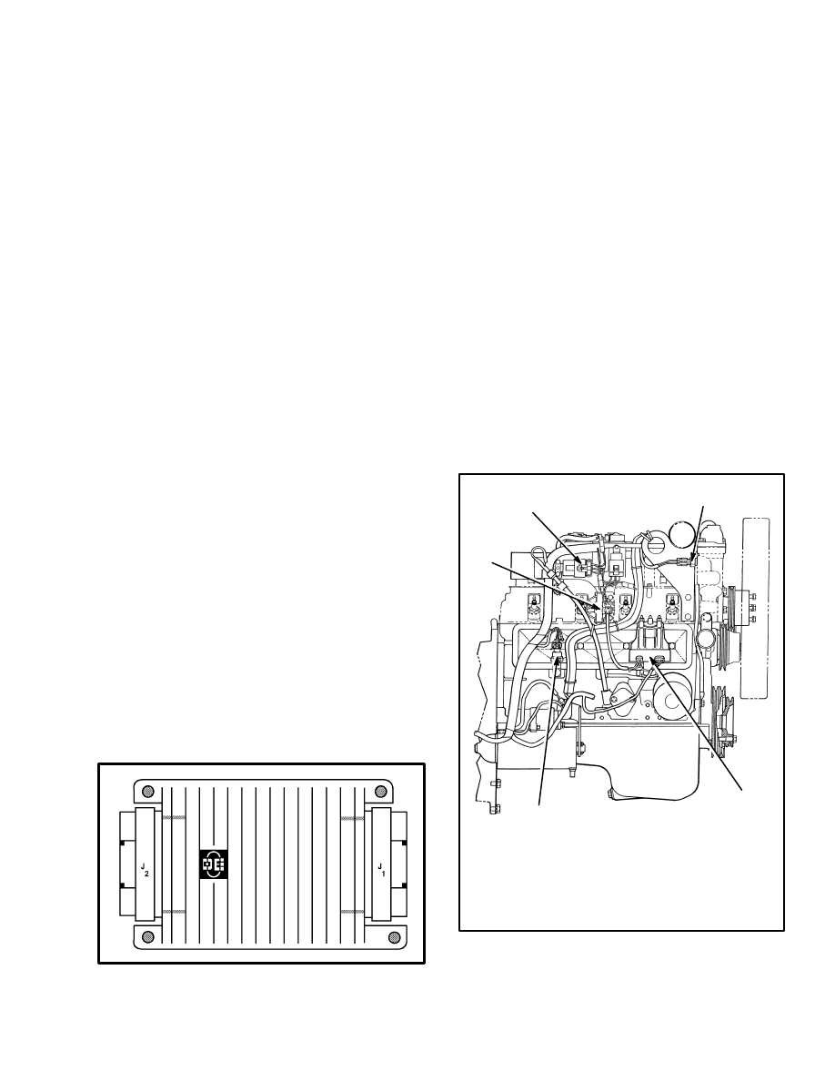
ELECTRONIC CONTROL MODULE (ECM)
(See FIGURE 1.)
The Electronic Control Module (ECM) is the control
center of the fuel injection system. It constantly moni-
tors the information from the sensors, and controls the
components and systems which affect engine operation.
The ECM also performs the diagnostic function of the
system. It can sense problems, activate the “Malfunc-
tion Indicator” lamp, and store a diagnostic trouble code
or codes (DTC). The ECM controls the following sys-
tems and components for the best fuel use and engine
performance:
FIGURE 1. ECM
•
Fuel Injection System
•
Electric Spark Timing (EST)
•
An electronic governor
•
“Check Engine” light
•
Idle air control (IAC)
•
Fuel pump relay
•
Diagnostic link connector (DLC) for trouble-
shooting
1. ENGINE COOLANT TEMPERATURE
(ECT) SENSOR
2. DISTRIBUTOR
3. OIL PRESSURE/FUEL PUMP SWITCH
4. IGNITION COIL
5. FUEL PUMP RELAY
SIDE VIEW
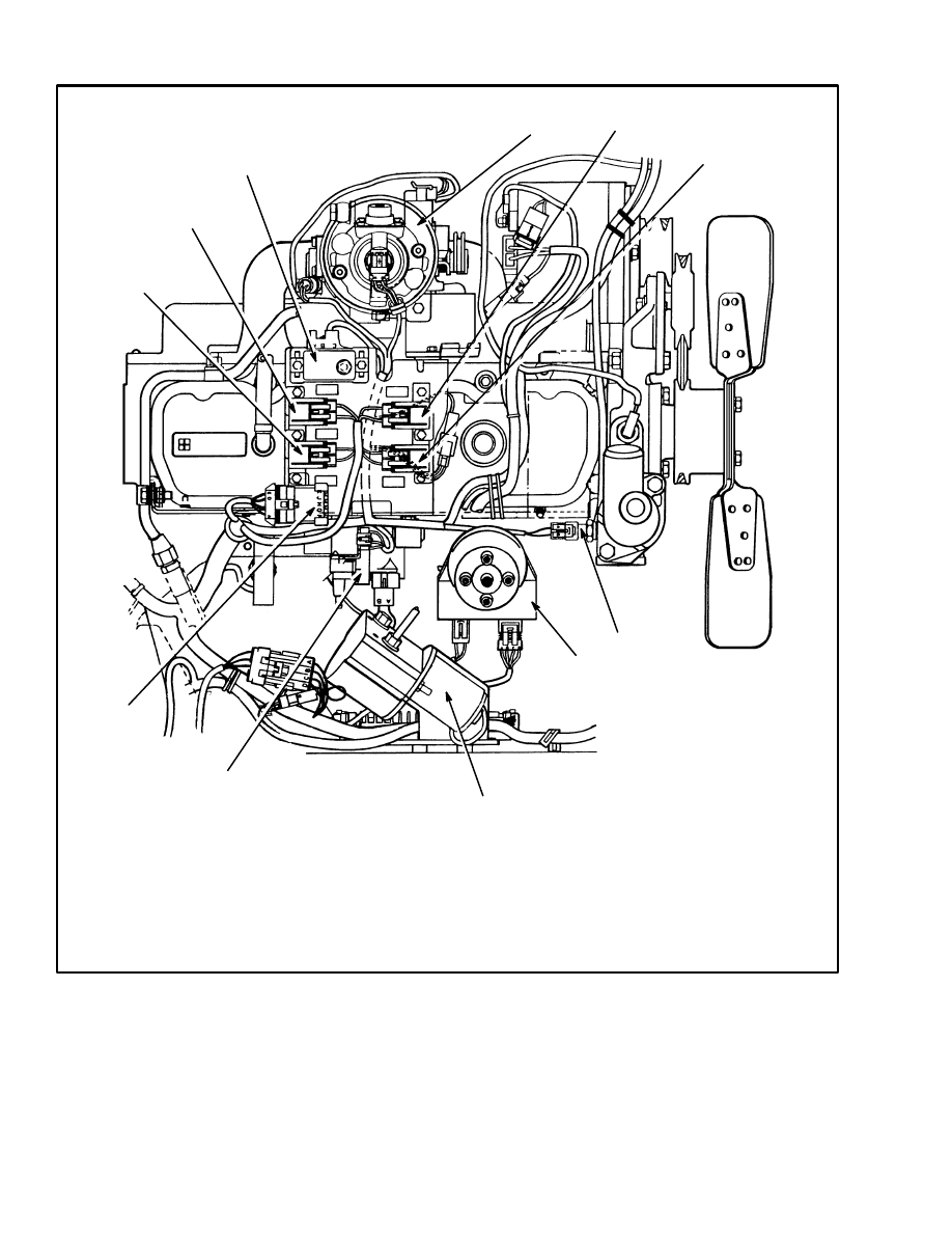
FIGURE 2. ARRANGEMENT OF COMPONENTS
FOR ELECTRONIC ENGINE CONTROL (1 of 2)
1
2
3
4
5
2
FIGURE 2. ARRANGEMENT OF COMPONENTS FOR ELECTRONIC ENGINE CONTROL (2 OF 2)
1. THROTTLE BODY INJECTION (TBI) UNIT
2. FUEL INJECTOR FUSE
3. IGNITION FUSE
4. ENGINE COOLANT TEMPERATURE (ECT)
SENSOR
5. DISTRIBUTOR
6. GOVERNOR MOTOR
TOP VIEW
7. IGNITION COIL
8. DIAGNOSTIC LINK CONNECTOR (DLC)
9. FUEL PUMP FUSE
10. ECM FUSE
11. MAP SENSOR
12909
1
2
3
4
5
6
7
8
9
10
11
3
How The ECM Begins Operation
When the ignition switch is turned to ON, the ECM does
the following functions:
•
Measures the atmospheric pressure (BARO sig-
nal) from the MAP sensor.
•
Checks the signal from the engine coolant tem-
perature (ECT) sensor.
•
Energizes the fuel pump relay for approximately
two seconds.
•
Checks that the throttle position sensor indicates
that the throttle is less than 80% open. (If the
throttle is more than 80% open, the ECM will de-
termine that the engine is flooded with fuel and
will deliver less fuel to the engine.)
•
EST Distributor System: Checks the starting
mode from the ignition module. [When the starter
is engaged, the ignition module sends electronic
pulses to the ECM. The frequency of the pulses
indicates to the ECM that the engine is being
started. The ignition module also electronically
energizes (ON) and deenergizes (OFF) the pri-
mary circuit of the ignition coil to create a spark at
the spark plugs.]
The ECM makes the checks in a few milliseconds and
determines the correct air and fuel ratio for starting the
engine. The range of this air and fuel ratio is 1.8:1 at
–40
°
C (–40
°
F) to 17:1 at 150
°
C (302
°
F) as indicated by
the signal from the engine coolant temperature sensor.
The ECM controls the amount of fuel sent to the engine
by changing the pulse times [how long the fuel injector
is energized (ON) and deenergized (OFF)].
When the engine starts, the frequency of the pulses from
the ignition module increases and indicates to the ECM
that the engine is running. The ECM takes control of the
ignition timing and fuel control for the best engine oper-
ation. When the engine is operating, the ECM continu-
ously checks the signals from the MAP, ECT, TPS and
engine speed sensors to make timing and fuel adjust-
ments for the engine operating conditions.
ELECTRONIC ENGINE CONTROL
What The ECM Does
The ECM receives signals from the following compo-
nents:
•
Manifold Absolute Pressure (MAP) sensor.
This sensor is a pressure transducer that measures
the atmospheric pressure before the engine is
started and the ECM uses this pressure as a refer-
ence. This sensor then measures changes in pres-
sure in the intake manifold during engine opera-
tion.
•
Engine Coolant Temperature (ECT) sensor.
This sensor is a thermistor (resistor that is cali-
brated to change its value as its temperature
changes) that monitors the engine coolant tem-
perature.
•
Throttle Position Sensor (TPS). This sensor in-
dicates the position of the throttle that is set by the
operator and is used with the indications from the
other sensors to determine the correct engine op-
eration.
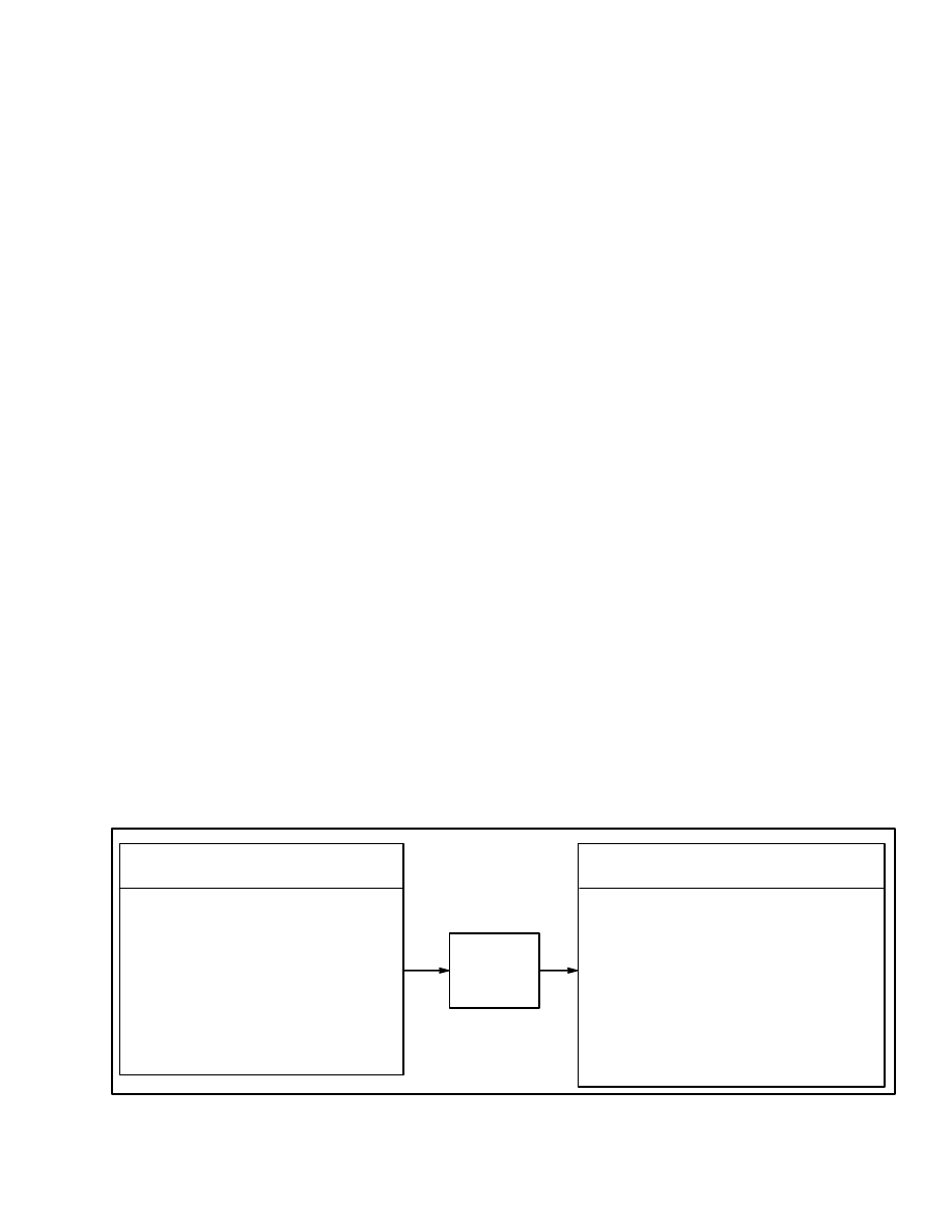
•
Engine Coolant Temperature
•
Engine Crank Signal
•
Distributor Reference
•
Engine Speed (rpm)
•
Manifold Absolute Pressure (MAP)
•
System Voltage
•
Throttle Position
•
Fuel Pump Voltage
OPERATING CONDITIONS
SENSED BY ECM
Electronic Spark Timing (EST)
Fuel Control
•
Idle Air Control
•
Electric Fuel Pump
•
Fuel Injection
Troubleshooting
•
“Check Engine” Light
•
Troubleshooting Terminal (DLC)
•
Data Output (DLC)
Governor Control
SYSTEMS CONTROLLED
BY ECM
ECM
FIGURE 3. ELECTRONIC ENGINE CONTROL SYSTEM
4
•
Fuel Pump. When the key switch is first turned
to “ON”, the ECM energizes the fuel pump relay
for two seconds. This action quickly raises the
fuel pressure to the fuel injectors. If the engine is
not cranked or started within two seconds, the
ECM deenergizes the fuel pump relay and the
fuel pump goes to “OFF”. When the engine is
cranked by the starter, the ECM energizes the fuel
pump relay again so that the fuel pump operates.
•
Ignition module. This component is a small
electronic module within the distributor. See
FIGURE 4. This ignition module is a signal con-
verter that senses the operation of the distributor.
A sensor coil in the distributor senses the rotation
of the timer core and the ignition module senses
the speed of rotation. A square wave generator in
the ignition module converts the pulses from the
sensor coil to a square wave signal that is sent to
the ECM. If the signals from the ignition module
to the ECM indicate that the crankshaft is rotating
at less than 400 rpm, the ECM determines that the
engine is being cranked by the starter. The igni-
tion module controls the ignition for an engine
being started. The Electronic Spark Timing
(EST) function from the ECM is deenergized. If
the signals from the ignition module to the ECM
indicate that the crankshaft is rotating at greater
than 400 rpm, the ECM determines that the en-
gine is running and the Electronic Spark Timing
(EST) controls the ignition.
•
Electronic governor. The ECM senses the en-
gine speed from the ignition module and operates
the governor motor on the throttle body to control
the engine speed. The governor motor will over-
ride the throttle position that is set by the operator
to control the engine speed within the limits set in
the ECM.
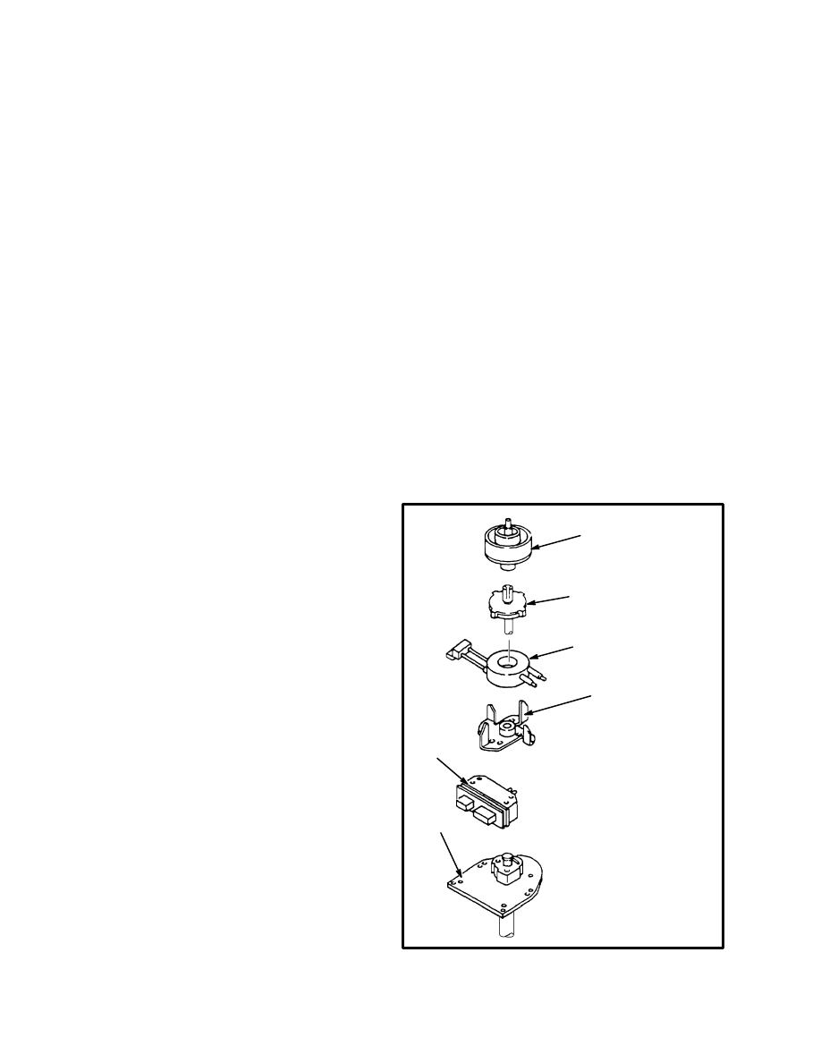
Distributor (See FIGURE 4.)
A timer core (permanent magnet) on the shaft of the dis-
tributor has external teeth which align with an equal
number of teeth on the pole piece. When the teeth of the
timer core rotate past the teeth of the pole piece, there is
a decrease in the air gap between the timer core and the
pole piece. The magnetic field increases. When teeth are
not aligned, the magnetic field decreases between the
timer core and the pole piece. As the timer core rotates,
the magnetic field increases and decreases in a cycle.
When a coil is near a changing magnetic field, a voltage
is generated in the coil. This principle is called magnetic
induction. A sensing coil is installed over the permanent
magnet. As the magnetic field near the pole piece
changes, a small voltage is generated in the sensing coil.
The principle of magnetic induction also controls the
polarity of the voltage generated in the coil. An increas-
ing magnetic field will generate a voltage in the coil that
is the opposite polarity of a magnetic field that is de-
creasing. This signal pulse causes the integrated circuits
in the ignition module to generate a square wave signal.
The ignition module and a magnetic pulse generator
control the primary circuit to the ignition coil when the
engine is started. The ECM receives the square wave
signal from the magnetic pulse generator and ignition
module as one of the signals to control the ignition. The
pole piece has the same number of teeth as the engine
has cylinders so that a spark voltage is correctly sent to
each spark plug as the shaft in the distributor rotates.
FIGURE 4. DISTRIBUTOR
1. ROTOR
2. TIMER
CORE/SHAFT
3. SENSING COIL
4. POLE PIECE
5. HOUSING
6. IGNITION
MODULE
1
2
3
4
5
6

5
Ignition Module
The ignition module is a solid–state electronic device
that operates like a fast switch except that it does not
have any moving or mechanical parts. See FIGURE 4.
Small electrical pulses from the sensing coil of the pulse
generator go to the ignition module.
The ECM must always know the speed at which the en-
gine is operating. The engine speed signal is generated
by the ignition module. The signal converter in the igni-
tion module changes the signal voltage from the sensing
coil to a square wave reference signal to the ECM. This
square wave reference signal for engine speed is called
“REF HI”. The ECM must also have a reference to com-
pare with “REF HI”. An additional wire between the
ECM and the EST module is called “REF LO”
(GROUND). The “REF HI” and “REF LO” connections
give the PROM in the ECM the necessary information
about engine speed.
The other two wires between the ECM and the distribu-
tor control the Electronic Spark Timing and are called
“EST” and “BY–PASS”.
NOTE: The ignition module controls spark timing only
when the the engine is being started or if the ECM fails.
The ECM controls the spark timing during engine oper-
ation. The ignition module will also control the spark
timing if there are some failures in the signals to the
ECM. This “back–up” mode of operation will often per-
mit operation of the engine so that the lift truck can be
moved to an area for repair. The result of failures in sig-
nals to the ECM is described in the paragraphs under
“Electronic Control Module (ECM) Corrections”.
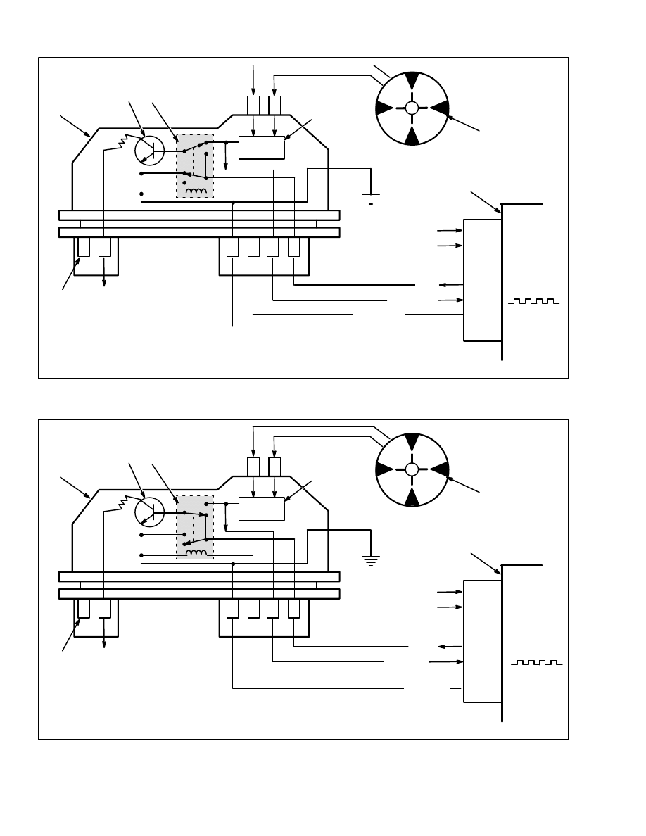
When The Engine Is Being Started
See FIGURE 5. When the engine is rotated by the start-
er, the electronic relay (2) is in the deenergized position.
The sensing coil is connected through the square wave
generator (3) to the base of the transistor (8).
When the sensing coil (4) applies a positive voltage (the
square wave voltage is increasing) to the transistor (8),
the transistor goes ON. When the voltage from the sens-
ing coil changes to negative (the square wave voltage is
decreasing), the transistor goes OFF. When the transis-
tor is ON, current flows through the primary winding of
the ignition coil. When the transistor goes OFF, the cur-
rent flow through the primary winding stops. The
changing magnetic field in the primary winding gener-
ates a high voltage in the secondary winding of the igni-
tion coil This high voltage generates a spark at the spark
plug.
When the Engine Is Running
See FIGURE 6. When the engine speed is approximate-
ly 400 rpm, the ECM determines that the engine is run-
ning and applies 5 volts on the “BY–PASS” wire to the
ignition module. This voltage energizes the electronic
relay (2) and makes the following changes: The “EST”
wire is not grounded and is now connected to the base of
the transistor (8). The sensing coil is disconnected from
the base of the transistor (8).
6
FIGURE 5. IGNITION MODULE WHEN ENGINE IS BEING STARTED
5
G
B
R
E
+
C
P
N
ÉÉÉÉ
ÉÉÉÉ
7
1
3
8
2
6
4
A
B
C
D
1. IGNITION MODULE
2. ELECTRONIC RELAY
3. SQUARE WAVE GENERATOR
4. SENSING COIL
5. ELECTRONIC CONTROL MODULE
6. BATTERY VOLTAGE
7. TO IGNITION COIL
8. TRANSISTOR
MAP SENSOR
ECT SENSOR
J2–23
J2– 8
J2–24
J2– 6
To Ground
No Voltage
Ground
EST
REF–LO
BY–PASS
REF–LO
FIGURE 6. IGNITION MODULE WHEN ENGINE IS RUNNING
5
G
B
R
E
+
C
P
N
ÉÉÉÉ
ÉÉÉÉ
ÉÉÉÉ
7
1
3
8
2
6
4
A
B
C
D
1. IGNITION MODULE
2. ELECTRONIC RELAY
3. SQUARE WAVE GENERATOR
4. SENSING COIL
5. ELECTRONIC CONTROL MODULE
6. BATTERY VOLTAGE
7. TO IGNITION COIL
8. TRANSISTOR
MAP SENSOR
ECT SENSOR
J2–23
J2– 8
J2–24
J2– 6
No Ground
5 Volts
Ground
EST
REF–LO
BY–PASS
REF–LO

7
The ignition module and the ignition timing is now con-
trolled by the “EST” signal from the ECM. This mode of
operation is called the “EST mode”.
Electronic Control Module (ECM) Corrections
The ECM does a check of the system components of the
EST. A set of normal operating limits are part of the
PROM program. If a sensor sends a signal that is outside
of the limits of the PROM program, the ECM will not
use the information. The ECM will use a standard value
from its program and continue to operate the EST.
The following examples are the action of the ECM if it
finds a problem:
MAP Sensor Signal Voltage Is Too High Or
Too Low. The ECM will use a MAP value from
its PROM program and use this value to calculate
the ignition timing.
ECT Signal Voltage Is Too High Or Too Low. If
the coolant sensor sends a signal voltage that is
outside of the range programmed by the ECM,
the ECM will determine that the engine is “cold”.
The ECM will use a value for a cold engine.
Open Circuit In EST Wire. Normally, the sig-
nal from the ECM to the ignition module rises
and falls as the voltage from the sensing coil rises
and falls. If the EST circuit is open, the electronic
relay in the ignition module is not at ground po-
tential.The engine will start but will not continue
to run. If the EST circuit becomes open during
engine operation, the engine will stop.
Short–Circuit (Grounded Circuit) In EST
Wire. When the engine is being rotated by the
starter, the ECM normally detects 0 volts in the
EST circuit because the circuit is at ground poten-
tial in the ignition module. The ECM would not
detect a problem until the engine began to run.
The ECM could not operate in the EST mode and
the engine will not operate. If the EST circuit has
a short–circuit (grounded circuit) when the en-
gine is running, it will stop.
Open Circuit Or Short–Circuit In The BY–
PASS Circuit. The ECM would not detect a
problem until the engine began to run. The ECM
could not operate in the EST mode and the engine
would operate with reduced power. If this prob-
lem occurs when the engine is running, the en-
gine will only operate in the starting mode.
Open Circuit Or Short–Circuit In The REF
HI Circuit. The ECM would not detect that the
engine was operating. The ECM could not oper-
ate in the EST mode and the engine will not oper-
ate.
Open Circuit Or Short–Circuit In The REF
LO Circuit. The ECM would not have a compar-
ison for operation. The ECM could not operate in
the EST mode and the engine will not operate
correctly.
What The ECM Does
The ECM receives signals from the following compo-
nents:
•
Manifold Absolute Pressure (MAP) sensor.
This sensor is a pressure transducer that measures
the atmospheric pressure before the engine is
started and the ECM uses this pressure as a refer-
ence. This sensor then measures changes in pres-
sure in the intake manifold during engine opera-
tion.
•
Engine Coolant Temperature (ECT) Sensor.
This sensor is a thermistor (resistor that is cali-
brated to change its value as its temperature
changes) that monitors the engine coolant tem-
perature.
•
Throttle position sensor (TPS). This sensor in-
dicates the position of the throttle that is set by the
operator and is used with the indications from the
other sensors to determine the correct engine op-
eration.
•
Fuel Pump. When the key switch is first turned
to “ON”, the ECM energizes the fuel pump relay
for two seconds. This action quickly raises the
fuel pressure to the fuel injectors. If the engine is
not cranked or started within two seconds, the
ECM deenergizes the fuel pump relay and the
fuel pump goes to “OFF”. When the engine is
cranked by the starter, the ECM energizes the fuel
pump relay again so that the fuel pump operates.
•
Engine speed sensor. If the signals from the EST
module to the ECM indicate that the crankshaft is
rotating at less than 400 rpm, the ECM deter-
mines that the engine is being cranked by the

8
starter. The ignition module controls the ignition
for an engine being started. The Electronic Spark
Timing (EST) function from the ECM is deener-
gized. If the signals from the ignition module to
the ECM indicate that the crankshaft is rotating at
greater than 400 rpm, the ECM determines that
the engine is running and the Electronic Spark
Timing (EST) controls the ignition.
•
Governor. The governor prevents engine speeds
above the specification when operating with light
loads, and permits the throttle to open for full
power for heavy loads. The operation of the gov-
ernor is described later in this section under
“Governor System.”
FUEL CONTROL OPERATION
The function of the fuel injection system is to deliver the
correct amount of fuel to the engine under all operating
conditions. Fuel is delivered by the Throttle Body Injec-
tion (TBI) unit, which is controlled by the Electronic
Control Module (ECM), based on certain operating
conditions. These conditions, which include engine
speed, manifold pressure, engine coolant temperature,
and throttle position, determine the “mode” of engine
operation. These modes are: Starting, Clear Excess Fuel
(Clear Flood), Run, Acceleration, Deceleration, and
Fuel Cut–off.
Starting Mode. When the key is first turned ON, the
ECM turns “ON” the fuel pump relay for two seconds,
and the fuel pump builds up fuel pressure at the TBI unit.
The ECM then monitors the coolant temperature,
throttle position, manifold pressure, and ignition signal
to determine the proper air/fuel ratio for starting. This
ranges from 1.5:1 at –36
°
C (–33
°
F) to 14.7:1 at 94
°
C
(201
°
F).
Clear Excess Fuel (clear flood) Mode. If the engine
does not start from excess fuel, it can be cleared by
pressing the accelerator pedal all the way to the floor.
The ECM then pulses the injector for an air to fuel ratio
of 20:1 or more. The ECM maintains this injector rate as
long as the throttle stays wide open and the engine speed
is below 600 rpm. If the throttle position becomes less
than 80%, the ECM returns to the Starting Mode.
Run Mode. The Run Mode is the mode under which the
engine operates most of the time. In this mode, the en-
gine operates on normal amounts of fuel.
Acceleration Mode. When the ECM senses rapid in-
crease in throttle position and manifold pressure, the
system enters the Acceleration Mode. In this mode, the
ECM gives the extra fuel needed for smooth accelera-
tion.
Deceleration Mode. When deceleration occurs, the
fuel remaining in the intake manifold can cause backfir-
ing. When the ECM observes a fast reduction in throttle
opening and a sharp decrease in manifold pressure, it
causes the system to enter the Deceleration Mode. In
this mode, the ECM reduces the amount of fuel deliv-
ered to the engine. When deceleration is very fast, the
ECM cuts off fuel completely for short periods.
Fuel Cut–Off Mode. To prevent possible engine dam-
age from over speed, the ECM will “cut–off” fuel from
the injector at about 3600 rpm. Fuel “cut–off” remains
in effect until engine speed drops below about 3600
rpm. (The governor would normally not allow the en-
gine to reach this condition.)
FUEL SYSTEM COMPONENTS
The fuel supply is kept in the fuel tank. An electric fuel
pump, located in the fuel tank, supplies fuel through a
filter to the TBI unit. (See FIGURE 7.) The pump deliv-
ers fuel at a pressure greater than is needed by the injec-
tor. A pressure regulator, part of the TBI assembly,
keeps fuel available to the injector. Fuel that is not used
is returned to the fuel tank by a separate line.
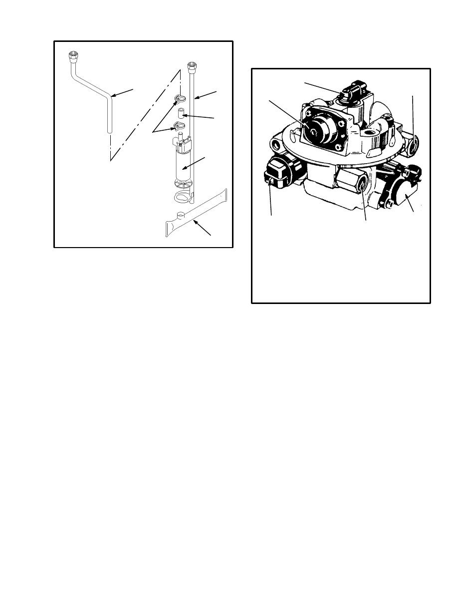
9
FIGURE 7. FUEL PUMP
1. OUTLET FUEL LINE
2. RETURN FUEL LINE
AND FUEL PUMP
SUPPORT
3. CLAMP (2)
4. FLEXIBLE COUPLING
5. FUEL PUMP AND
MOTOR
6. SCREEN
2
1
3
4
5
6
ÂÂÂÂÂ
ÂÂÂÂÂ
ÂÂÂÂÂ
ÂÂÂÂÂ
Fuel Pump Electrical Circuit
When the ignition switch is turned to the ON position
(engine not running), the ECM turns the fuel pump relay
“ON” for two seconds. This action quickly raises the
fuel pressure to the fuel injector. If the engine is not
started within two seconds, the ECM deenergizes the
fuel pump relay and the fuel pump goes to OFF. When
the engine is cranked by the starter, the ECM energizes
the fuel pump relay again so that the fuel pump operates.
As a parallel system to the fuel pump relay, the fuel
pump also can be turned “ON” by the oil pressure
switch. The oil pressure sender has two internal circuits.
One circuit operates the oil pressure indicator or gage in
the instrument cluster, and the other is a normally open
switch that closes when oil pressure reaches approxi-
mately 28 kPa (4 psi). If the fuel pump relay has a fault,
the oil pressure switch runs the fuel pump.
Throttle Body Injection (See FIGURE 8.)
The TBI unit consists of two major assemblies; the
Throttle Body and the Fuel Meter Body. The parts of the
Throttle Body are the Throttle Position (TP) Sensor, Idle
Air Control (IAC) Valve, Throttle Valve and the Tube
Module Assembly. The Fuel Meter Body has the Fuel
Injector and the Fuel Pressure Regulator
FIGURE 8. THROTTLE BODY INJECTION
(TBI) UNIT
1. FUEL INJECTOR
2. FUEL INLET
3. THROTTLE POSITION SENSOR
4. FUEL OUTLET
5. IDLE AIR CONTROL VALVE
6. FUEL PRESSURE REGULATOR
1
2
3
4
6
5
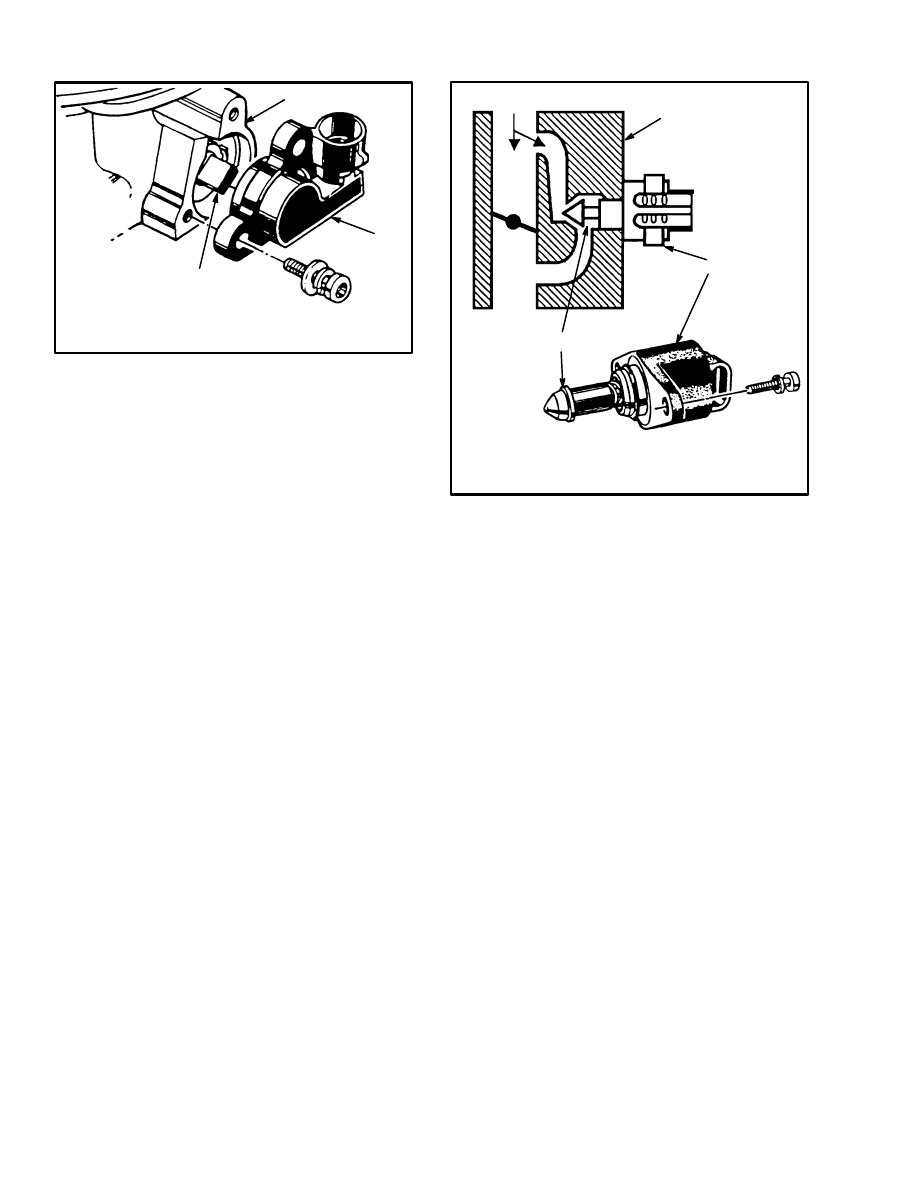
Throttle Position (TP) Sensor
The Throttle Position (TP) Sensor is a potentiometer
that is connected to the throttle shaft on the throttle body.
It senses the position of the throttle plate and sends that
information to the ECM. This information permits the
ECM to generate the correct pulses to the fuel injector
for fuel control. If the throttle position sensor indicates a
fully opened throttle to the ECM, the ECM then in-
creases the pulse width to the fuel injector.
The TP Sensor electrical circuit has a 5 volt supply line
and a ground path line, both from the ECM. A third wire
is used as a signal line to the ECM. By monitoring the
voltage on this signal line, the ECM calculates throttle
position. As the throttle plate angle is changed (acceler-
ator pedal moved), the signal voltage of the TP Sensor
also changes. At a closed throttle position, the signal of
the TP Sensor is below 1.25volts. As the throttle plate
opens, the signal voltage increases, so that at wide open
throttle, it is approximately 5 volts.
10
1. THROTTLE BODY ASSEMBLY
2. THROTTLE POSITION SENSOR
3. THROTTLE SHAFT
FIGURE 9. THROTTLE POSITION SENSOR
1
2
3
Idle Air Control (IAC) Valve
(See FIGURE 10.)
The idle speed of the engine is controlled by the ECM
through the Idle Air Control (IAC) valve. The idle air
control valve has a linear DC step motor that moves a
pintle valve to control the idle air system. See
FIGURE 10. The step motor moves the pintle one step
for each “count” that it receives from the ECM. Each
voltage pulse from the ECM to move the pintle valve is a
count. This movement of the pintle valve controls the air
flow around the throttle plate. (When the pintle valve is
EXTENDED, it decreases air flow and when RE-
TRACTED, it increases air flow.) This air flow controls
the engine idle speed at all operating temperatures. A
minimum setting is for engine idle at sea level and nor-
mal conditions. A heavier load from the alternator, hy-
draulic pump or other accessories will cause the ECM to
set a higher number of counts on the pintle valve.
The number of counts that indicates the position of the
pintle valve can be seen when the “scan” tool is con-
nected for troubleshooting.
Pintle Extended = Decrease rpm = Lower Counts.
Pintle Retracted = Increase rpm = Higher Counts.
1. THROTTLE BODY
2. LINEAR DC STEP MOTOR
3. PINTLE VALVE
FIGURE 10. IDLE AIR CONTROL VALVE
1
AIR FLOW
2
3
Fuel Injector
The fuel injector is a solenoid that is controlled by the
ECM. When the ECM energizes the solenoid, a normal-
ly closed ball valve is lifted off its seat. The fuel is under
constant pressure and is injected in a cone spray pattern
into the bore of the throttle body, above the throttle plate.
The fuel that is not used by the fuel injector flows
through the pressure regulator and returns to the fuel
tank.
Fuel Pressure Regulator
The fuel pressure regulator is part of the fuel metering
assembly of the TBI. The function of the fuel pressure
regulator is to maintain a constant fuel pressure at the in-
jector during all operating modes. An air chamber and a
fuel chamber are separated by a diaphragm–operated re-
lief valve and a calibrated spring. Fuel pressure at the
fuel injector is controlled by the difference in pressure
on each side of the diaphragm. The fuel pressure from
the fuel pump on one side of the diaphragm acts against
the force of the calibrated spring on the other side of the
diaphragm. The system operates in a pressure range of
62 to 90 kPa (9 to 13 psi).
The fuel meter assembly includes a vapor relief hole that
relieves system pressure when the engine is turned OFF.
11
This hole also helps release vapors from the injector and
regulator for starting a hot engine.
Idle Speed Control
The ECM uses two basic items to control idle rpm. The
Idle Air Control (IAC) valve and spark timing are ad-
justed to give the correct idle rpm. During varying idle
loads and engine temperature the ECM must be able to
keep the engine running at the correct rpm.
Spark timing varies engine speed by varying the engine
power output. IAC valve changes the air delivered to the
engine which also changes the engine output.
Also remember that air can enter the engine in other
areas. One is by the throttle plate and another is the PCV
valve. Vacuum leaks can affect idle speed.
Maximum RPM Control
There are two items that control maximum engine rpm.
One is the ECM fuel cut–off, and the other is a governor
system. Fuel cut–off is used only if the governor system
malfunctions.
Governor speed control is a lower rpm value. This sys-
tem uses a cable drum that is driven by a motor. The mo-
tor is controlled by a governor module. When a cali-
brated rpm is reached, the ECM sends a signal to the
module which in turn runs the motor. The throttle plate
on the throttle body is driven toward the closed position
to limit engine rpm.
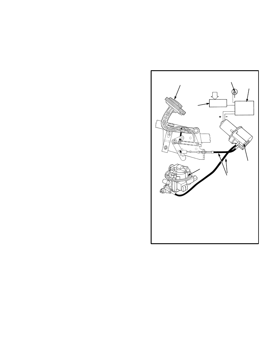
GOVERNOR SYSTEM (See FIGURE 11.)
The governor motor is an electric DC motor that is actu-
ated and controlled by the Electronic Control Module
(ECM) through the governor control module (governor
motor driver circuit). The governor prevents engine
speeds above specifications when operating with light
loads, and permits the throttle to open for full power for
heavy loads.
The components of the governor system are the ECM,
the governor control module and the governor motor as-
sembly and cables. The cables and drum allow the
throttle control to be split. This split arrangement allows
the governor motor drum to close the throttle plate, yet
open them indirectly. The first drum is turned by the ac-
celerator pedal. A spring located inside the drum pushes
on the second drum. This action allows the operator to
open the throttle when under heavy load, but the motor
will rotate the drum, against the spring, to close the
throttle plate under light load–high rpm. Using engine
speed and load, the governor controls the actual position
of the throttle plate, within that range of possible open-
ing.
FIGURE 11. GOVERNOR SYSTEM
1. SENSOR INPUTS
2. KEY SWITCH
3. GOVERNOR CONTROL MODULE
4. GOVERNOR
5. THROTTLE CABLES
6. TBI UNIT
7. THROTTLE (MONOTROL) PEDAL
8. ELECTRONIC CONTROL MODULE (ECM)
1
8
2
3
4
6
7
5
The engine sensors, such as the Throttle Position (TP)
Sensor, Manifold Absolute Pressure (MAP) sensor, and
crankshaft reference pulses (rpm) gives constant in-
formation on engine operating conditions to the Elec-
tronic Control Module (ECM). The ECM uses the in-
formation on throttle plate position and engine rpm to
determine whether or not governed operation is needed.
At low engine speeds, below calibration rpm, the gover-
nor drive motor is not energized. At higher engine
speeds, above calibration rpm, where the governor is
needed, the ECM sends a signal to the governor control
12
module to increase current flow to the governor motor.
The governor motor rotates the drum and this causes the
throttle plate to rotate toward the closed position. Con-
trol of the throttle plate is determined by the TP Sensor
and engine speed signals to the ECM. When engine load
increases and rpm decreases, the electrical current to the
motor is reduced by the ECM through the governor con-
trol module, thus allowing the throttle plate to open far-
ther.
ECM SENSORS AND CONTROLLERS
Manifold Absolute Pressure
(MAP) Sensor (See FIGURE 12.)
The Manifold Absolute Pressure (MAP) sensor is a
pressure transducer that measures pressure changes in
the intake manifold. Pressure changes are the result of
engine load and speed changes. The MAP sensor con-
verts these pressure changes to a signal voltage to the
ECM.
A closed throttle causes a low pressure (high engine vac-
uum) in the intake manifold. This low pressure causes a
low voltage signal from the MAP sensor to the ECM. A
fully opened throttle causes a higher pressure (low en-
gine vacuum) in the intake manifold. This higher pres-
sure causes a higher voltage signal from the MAP sensor
to the ECM. These pressure changes indicate the load on
the engine and sends a signal to the ECM. The ECM then
calculates the spark timing and fuel requirements for
best engine performance.
The MAP sensor also measures barometric pressure
when the key switch is turned to ON and before the en-
gine is started. The ECM “remembers” the barometric
pressure (BARO signal) after the engine is running.
This method enables the ECM to automatically adjust
for different altitudes and atmospheric conditions.
The ECM supplies 5 volts to the MAP sensor and moni-
tors the voltage on a signal line. The sensor provides a
path to ground through its variable resistance. The MAP
sensor signal affects fuel delivery and ignition timing
controls in the ECM.
FIGURE 12. MANIFOLD ABSOLUTE
PRESSURE (MAP) SENSOR
2
1
1. SENSOR
2. ELECTRICAL CONNECTOR
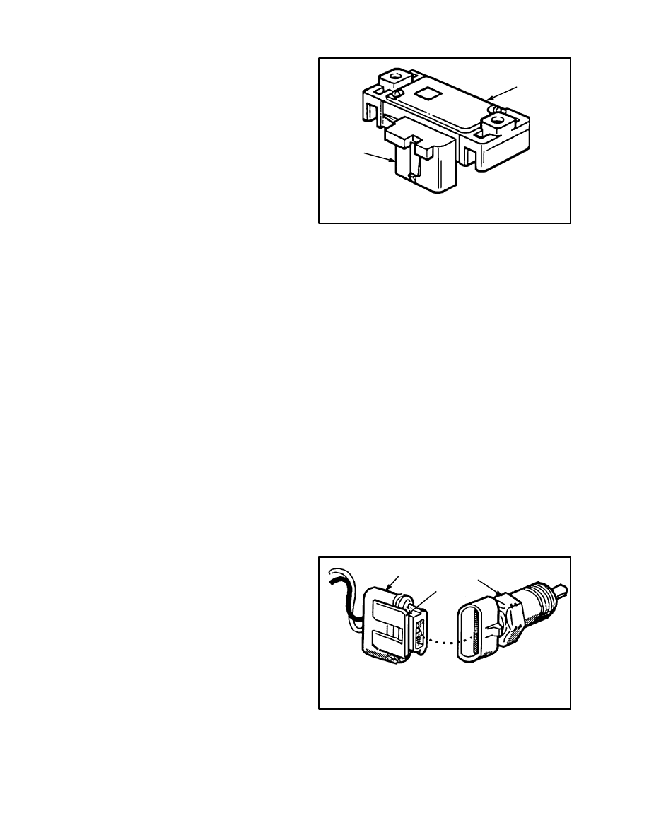
Engine Coolant Temperature
(ECT) Sensor (See FIGURE 13.)
The Engine Coolant Temperature (ECT) Sensor is a re-
sistor that changes its resistance when the temperature
changes (thermistor). It is installed in the engine coolant
system. Low coolant temperature causes high resis-
tance; 100,000 ohms at –40
°
C (–40
°
F). High tempera-
ture causes low resistance; 70 ohms at 130
°
C (266
°
F).
The ECM applies 5 volts to the coolant sensor and moni-
tors the voltage on a signal line. The sensor provides a
path to ground through its thermistor. The voltage will
be high when the engine is cold, and low when the en-
gine is hot. By monitoring the voltage, the ECM deter-
mines the engine coolant temperature. Engine coolant
temperature affects most of the ECM functions.
FIGURE 13. COOLANT TEMPERATURE
SENSOR (CTS)
1. TEMPERATURE SENSOR
2. ELECTRICAL CONNECTOR
3. LOCK TAB
2
1
3
13
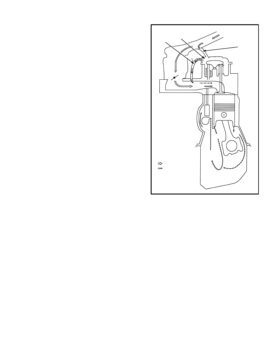
POSITIVE CRANKCASE VENTILATION
(See FIGURE 14.)
The Positive Crankcase Ventilation (PCV) system is
used as a vent for vapors from the crankcase. Clean air
from the air cleaner is supplied to the crankcase, mixed
with gases from the valve cover. This mixture then goes
through the Positive Crankcase Ventilation (PCV) valve
into the intake manifold. For correct engine idle, the
PCV valve restricts the flow when there is high vacuum
at the intake manifold.
The incorrect operation of the PCV system can be:
•
Rough idle
•
Stalling or slow idle speed
•
High idle speed
•
Oil leak
•
Oil in the air filter
FIGURE 14. POSITIVE CRANKCASE
VENTILATION SYSTEM
A
B
C
D
A. PCV VALVE
B. PCV VALVE
HOSE
C. AIR FILTER
D. CRANKCASE
VENT HOSE
CLEAN AIR
MIXTURE OF
AIR AND
FUMES
Document Outline
- INTRODUCTION
- DESCRIPTION AND OPERATION
Wyszukiwarka
Podobne podstrony:
897844 2200SRM0603 (01 1996) UK EN
897844 2200SRM0603 (01 1996) UK EN
897070 2200SRM0288 (01 1994) UK EN
897415 2200SRM0464 (01 1994) UK EN
897495 2200SRM0514 (01 2004) UK EN
1564268 2200SRM1106 (01 2004) UK EN
1595265 2200SRM1204 (01 2005) UK EN
897928 2200SRM0625 (12 1996) UK EN
1556871 2200SRM1105 (01 2004) UK EN
więcej podobnych podstron