
For our other free eBooks,
50 - 555 Circuits
1 - 100 Transistor Circuits
and:
101 - 200 Transistor Circuits
100 IC Circuits
For a list of every electronic symbol, see:
Circuit Symbols
.
For more articles and projects for the hobbyist: see
TALKING ELECTRONICS
WEBSITE
email Colin Mitchell:
talking@tpg.com.au
CONTENTS
Battery Monitor
MkI
MkII
Bi-Coloured LED
Bike Turning Signal
Bi-Polar LED Driver
Dice
Domino Effect
- The
Driving A Bi-Coloured LED
Driving White LEDs
Fading LED
Flashing A LED
Flashing Railroad Lights
Kitt Scanner
Knight Rider
LED Chaser
LED Detects Light
LED Dice
LED Dimmer
Police Lights
1,2,3
Powering A Project
Railroad Lights (flashing)
RGB LED Driver
RGB LED Flasher
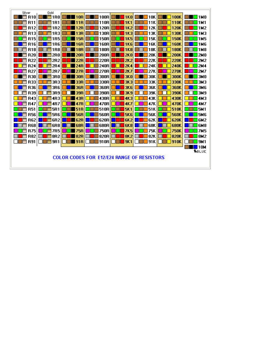
Resistor Colour Codes
Roulette
Shake LED Torch
Solar Garden Light
Solar Tracker
The Domino Effect
Traffic Lights
Traffic Lights - 4 way
Turning Signal
Up/Down Fading LED
Up/Down Fading LED - 2
White LED on 1.5v Supply

LED FX
LED Night Light
LEDs on 120v and 240v
LED Zeppelin
Lights - Traffic Lights
Low Fuel Indicator
Mains Night Light
White LED Flasher
2 White LEDs on 1.5v Supply
3x3x3 Cube
4 way Traffic Lights
8 Million Gain!
10 LED Chaser
120v and 240v LEDs
INTRODUCTION
This e-book covers the Light Emitting Diode.
The LED (Light Emitting Diode) is the modern-day equivalent to the light-globe.
It has changed from a dimly-glowing indicator to one that is too-bright to look at.
However it is entirely different to a "globe."
A globe is an electrical device consisting of a glowing wire while a LED is an electronic device.
A LED is more efficient, produces less heat and must be "driven" correctly to prevent it being
damaged.
This eBook shows you how to connect a LED to a circuit plus a number of projects using LEDs.
It's simple to use a LED - once you know how.
CONNECTING A LED
A LED must be connected around the correct way in a circuit and it must have a resistor to limit the
current.
The LED in the first diagram does not illuminate because a red LED requires 1.7v and the cell only
supplies 1.5v. The LED in the second diagram is damaged because it requires 1.7v and the two cells
supply 3v. A resistor is needed to limit the current to about 25mA and also the voltage to 1.7v, as
shown in the third diagram. The fourth diagram is the circuit for layout #3 showing the symbol for
the LED, resistor and battery and how the three are connected. The LED in the fifth diagram does
not work because it is around the wrong way.
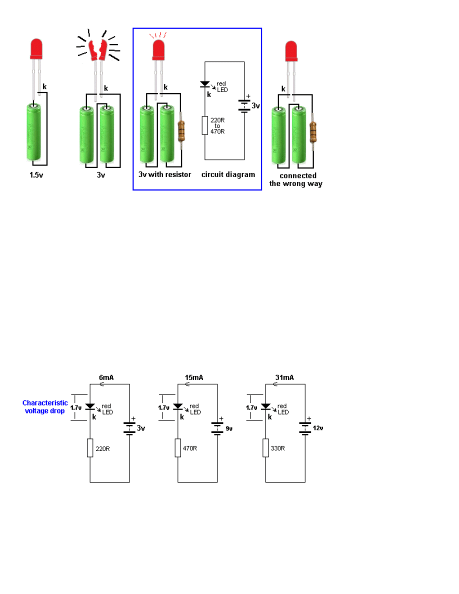
CHARACTERISTIC VOLTAGE DROP
When a LED is connected around the correct way in a circuit it develops a voltage across it called
the CHARACTERISTIC VOLTAGE DROP.
A LED must be supplied with a voltage that is higher than its "CHARACTERISTIC VOLTAGE" via a
resistor - called a VOLTAGE DROPPING RESISTOR or CURRENT LIMITING RESISTOR - so the LED will
operate correctly and provide at least 10,000 to 50,000 hours of illumination.
A LED works like this: A LED and resistor are placed in series and connected to a voltage.
As the voltage rises from 0v, nothing happens until the voltage reaches about 1.7v. At this voltage a
red LED just starts to glow. As the voltage increases, the voltage across the LED remains at 1.7v but
the current through the LED increases and it gets brighter.
We now turn our attention to the current though the LED. As the current increases to 5mA, 10mA,
15mA, 20mA the brightness will increase and at 25mA, it will be a maximum. Increasing the supply
voltage will simply change the colour of the LED slightly but the crystal inside the LED will start to
overheat and this will reduce the life considerably.
This is just a simple example as each LED has a different CHARACTERISTIC VOLTAGE DROP and a
different maximum current.
In the diagram below we see a LED on a 3v supply, 9v supply and 12v supply. The current-limiting
resistors are different and the first circuit takes 6mA, the second takes 15mA and the third takes
31mA. But the voltage across the red LED is the same in all cases. This is because the LED creates
the CHARACTERISTIC VOLTAGE DROP and this does not change.
It does not matter if the resistor is connected above or below the LED. The circuits are the SAME in
operation:
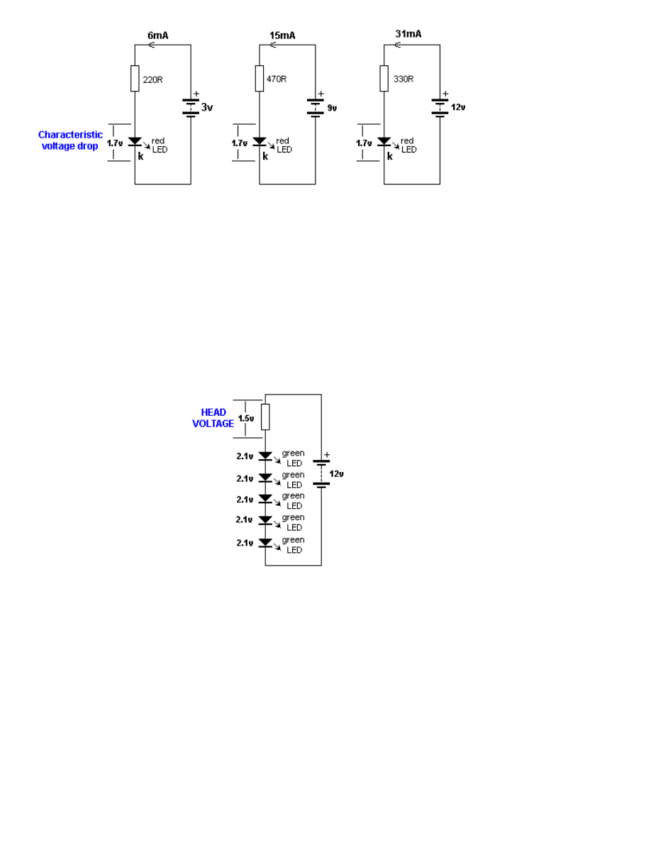
HEAD VOLTAGE
Now we turn our attention to the resistor.
As the supply-voltage increases, the voltage across the LED will be constant at 1.7v (for a red LED)
and the excess voltage will be dropped across the resistor. The supply can be any voltage from 2v to
12v or more.
In this case, the resistor will drop 0.3v to 10.3v.
This is called HEAD VOLTAGE - or HEAD-ROOM.
The following diagram shows HEAD VOLTAGE:
The voltage dropped across this resistor, combined with the current, constitutes wasted energy and
should be kept to a minimum, but a small HEAD VOLTAGE is not advisable (such as 0.5v). The head
voltage should be a minimum of 1.5v - and this only applies if the supply is fixed.
The head voltage depends on the supply voltage. If the supply is fixed and guaranteed not to
increase or fall, the head voltage can be small (1.5v minimum).
But most supplies are derived from batteries and the voltage will drop as the cells are used.
Here is an example of a problem:
Supply voltage: 12v
7 red LEDs in series = 11.9v
Dropper resistor = 0.1v
As soon as the supply drops to 11.8v, no LEDs will be illuminated.
Example 2:
Supply voltage 12v
5 green LEDs in series @ 2.1v = 10.5v
Dropper resistor = 1.5v
The battery voltage can drop to 10.5v
But let's look at the situation more closely.
Suppose the current @ 12v = 25mA.
As the voltage drops, the current will drop.
At 11.5v, the current will be 17mA
At 11v, the current will be 9mA
At 10.5v, the current will be zero
You can see the workable supply drop is only about 1v.
Many batteries drop 1v and still have over 80% of their energy remaining. That's why you need to
design your circuit to have a large HEAD VOLTAGE.
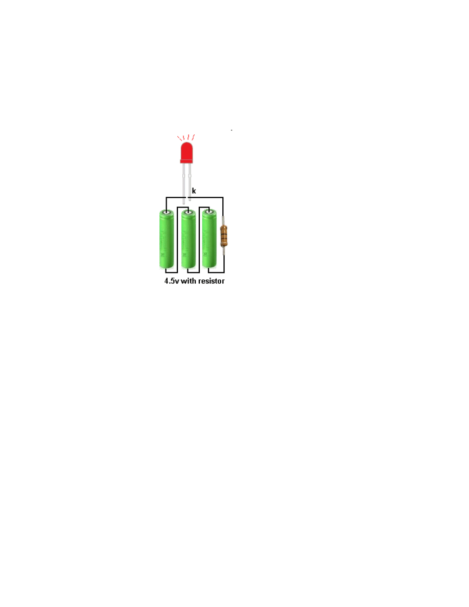
TESTING A LED
If the cathode lead of a LED cannot be identified, place 3 cells in series with a 220R resistor and
illuminate the LED. 4.5v allows all types of LEDs to be tested as white LEDs require up to 3.6v. Do
not use a multimeter as some only have one or two cells and this will not illuminate all types of
LEDs. In addition, the negative lead of a multimeter is connected to the positive of the cells (inside
the meter) for resistance measurements - so you will get an incorrect determination of the cathode
lead.
CIRCUIT TO TEST ALL TYPES OF LEDs
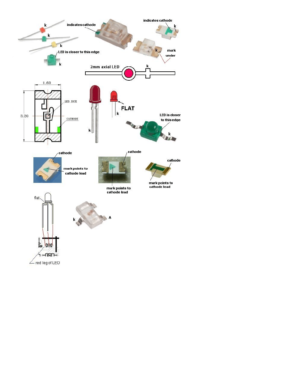
IDENTIFYING A LED
A LED does not have a "Positive" or "Negative" lead. It has a lead identified as the "Cathode" or
Kathode" or "k". This is identified by a flat on the side of the LED and/or by the shortest lead.
This lead goes to the 0v rail of the circuit or near the 0v rail (if the LED is connected to other
components).
Many LEDs have a "flat" on one side and this identifies the cathode. Some surface-mount LEDs have
a dot or shape to identify the cathode lead and some have a cut-out on one end.
Here are some of the identification marks:
LEDs ARE CURRENT DRIVEN DEVICES
A LED is described as a CURRENT DRIVEN DEVICE. This means the illumination is determined by the
amount of current flowing through it.
The brightness of a LED can be altered by increasing or decreasing the current. The effect will not
be linear and it is best to experiment to determine the best current-flow for the amount of
illumination you want. High-bright LEDs and super-bright LEDs will illuminate at 1mA or less, so the
quality of a LED has a lot to do with the brightness. The life of many LEDs is determined at 17mA.
This seems to be the best value for many types of LEDs.
1mA to 5mA LEDs
Some LEDs will produce illumination at 1mA. These are "high Quality" or "High Brightness" LEDs and
the only way to check this feature is to test them @1mA as shown below.

THE 5v LED
Some suppliers and some websites talk about a 5v white or blue LED. Some LEDs have a small
internal resistor and can be placed on a 5v supply. This is very rate.
Some websites suggest placing a white LED on a 5v supply. These LEDs have a characteristic voltage-
drop of 3.6v and should not be placed directly on a voltage above this value.
The only LED with an internal resistor is a FLASHING LED. These LEDs can be placed on a supply
from 5v to 12v and flash at approx 2Hz.
NEVER assume a LED has an internal resistor. Always add a series resistor. Some high intensity LEDs
are designed for 12v operation. These LEDs have a complete internal circuit to deliver the correct
current to the LED. This type of device is not covered in this eBook.
LEDs IN SERIES
LEDs can be placed in series providing some features are taken into account. The main item to
include is a current-limiting resistor.
A LED and resistor is called a string. A string can have 1, 2, 3 or more LEDs.
Three things must be observed:
1. MAXIMUM CURRENT through each string = 25mA.
2. The CHARACTERISTIC VOLTAGE-DROP must be known so the correct number of LEDs are used in
any string.
3. A DROPPER RESISTOR must be included for each string.
The following diagrams show examples of 1-string, 2-strings and 3-strings:
LEDs IN PARALLEL
LEDs
CANNOT
be placed in parallel - until you read this:
LEDs "generate" or "possess" or "create" a voltage across them called the CHARACTERISTIC VOLTAGE-
DROP (when they are correctly placed in a circuit).
This voltage is generated by the type of crystal and is different for each colour as well as the
"quality" of the LED (such as high-bright, ultra high-bright etc). This characteristic cannot be altered
BUT it does change a very small amount from one LED to another in the same batch. And it does
increase slightly as the current increases.
For instance, it will be different by as much as 0.2v for red LEDs and 0.4v for white LEDs from the
same batch and will increase by as much as 0.5v when the current is increased from a minimum to
maximum.
You can test 100 white LEDs @15mA and measure the CHARACTERISTIC VOLTAGE-DROP to see this
range.
If you get 2 LEDs with identical CHARACTERISTIC VOLTAGE-DROP, and place them in parallel, they
will each take the same current. This means 30mA through the current-limiting resistor will be
divided into 15mA for each LED.
However if one LED has a higher CHARACTERISTIC VOLTAGE-DROP, it will take less current and the
other LED will take considerably more. Thus you have no way to determine the "current-sharing" in
a string of parallel LEDs. If you put 3 or more LEDs in parallel, one LED will start to take more
current and will over-heat and you will get very-rapid LED failure. As one LED fails, the others will
take more current and the rest of the LEDs will start to self-destruct.
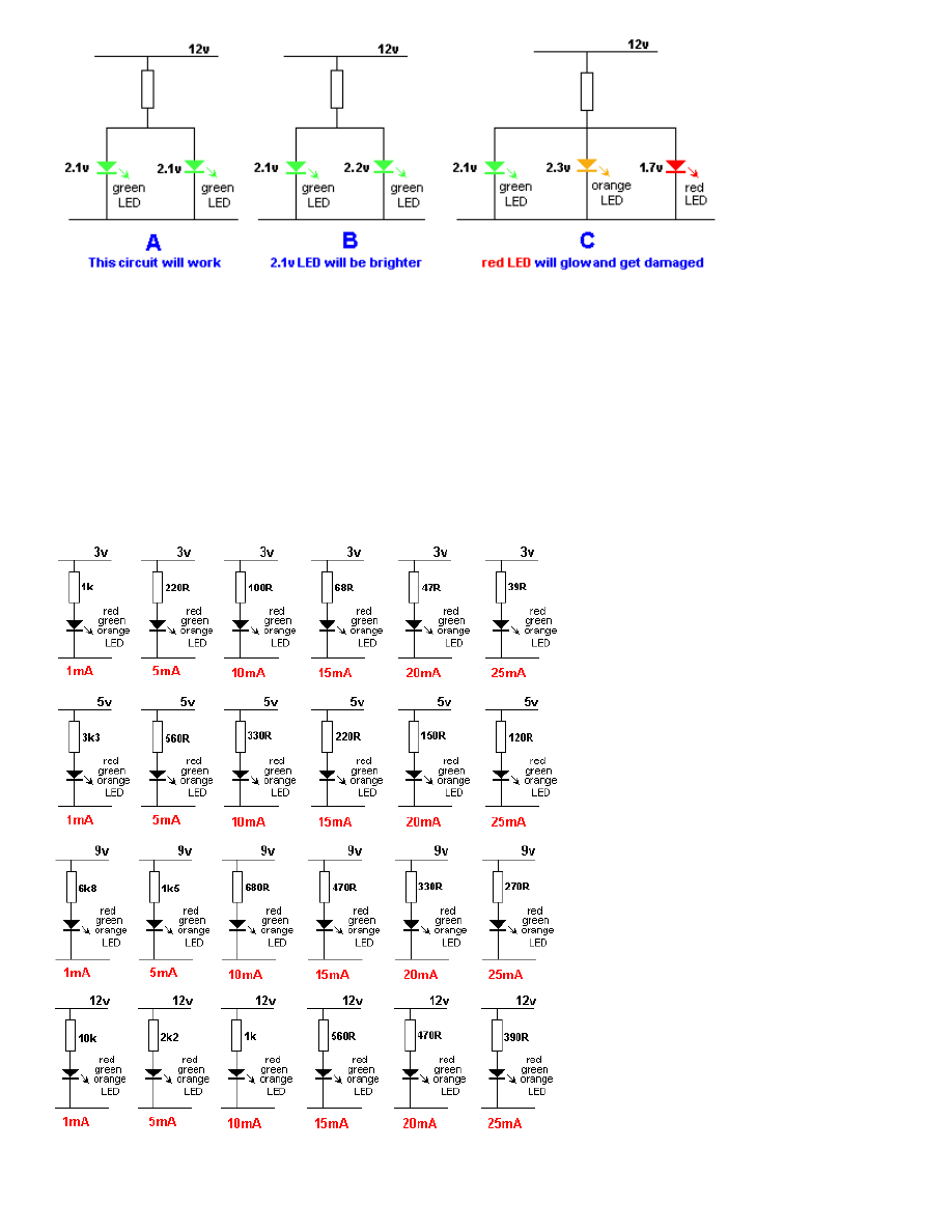
Thus LEDs in PARALLEL should be avoided.
Diagram
A
below shows two green LEDs in parallel. This will work provided the Characteristic
Voltage Drop across each LED is the same.
In diagram
B
the Characteristic Voltage Drop is slightly different for the second LED and the first
green LED will glow brighter.
In diagram
C
the three LEDs have different Characteristic Voltage Drops and the red LED will glow
very bright while the other two LEDs will not illuminate. All the current will pass through the red
LED and it will be damaged.
The reason why the red LED will glow very bright is this: It has the lowest Characteristic Voltage
Drop and it will create a 1.7v for the three LEDs. The green and orange LEDs will not illuminate at
this voltage and thus all the current from the dropper resistor will flow in the red LED and it will be
destroyed.
THE RESISTOR
The value of the current limiting resistor can be worked out by Ohms Law.
Here are the 3 steps:
1. Add up the voltages of all the LEDs in a string. e.g: 2.1v + 2.3v + 2.3v + 1.7v = 8.4v
2. Subtract the LED voltages from the supply voltage. e.g: 12v - 8.4v = 3.6v
3. Divide the 3.6v (or your voltage) by the current through the string.
for 25mA: 3.6/.025 =144 ohms
for 20mA: 3.6/.02 = 180 ohms
for 15mA: 3.6/.015 = 250 ohms
for 10mA: 3.6/.01 = 360 ohms
This is the value of the current-limiting resistor.
Here is a set of strings for a supply voltage of 3v to 12v and a single LED:
Here is a set of strings for a supply voltage of 5v to 12v and a white LED:
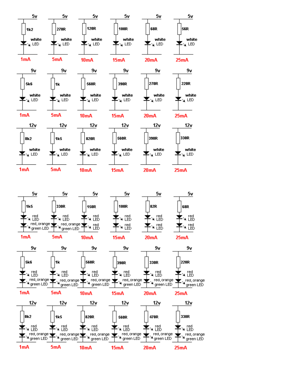
Here is a set of strings for a supply voltage of 5v to 12v and two LEDs:
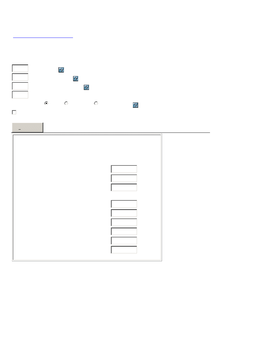
LED series/parallel array wizard
The LED series/parallel array wizard below, is a calculator that will help you design large arrays of
single-colour LEDs.
This calculator has been designed by Rob Arnold and you will be taken to his site:
http://led.linear1.org/led.wiz
when you click: Design my array
The wizard determines the current limiting resistor value for each string of the array and the power
consumed. All you need to know are the specs of your LED and how many you'd like to use. The
calculator only allows one LED colour to be used. For mixed colours, you will have to use the 3 steps
explained above.
Source voltage
diode forward voltage
diode forward current (mA)
number of LEDs in your array
View output as:
ASCII
schematic
wiring diagram
help with resistor colour codes
Design my array
Resistor Calculator
Use this JavaScript resistor calculator to work out the
value of the current-limiting resistor:
Source voltage
=
12.6
LED forward voltage drop
=
3.6
LED current in milliamps
=
25
Current-limiting resistance in Ohms
=
Closest 5% Resistor
=
Resistor wattage
=
Actual current
=
Power dissipated by LED (watts)
=
Power dissipated by resistor (watts)
=
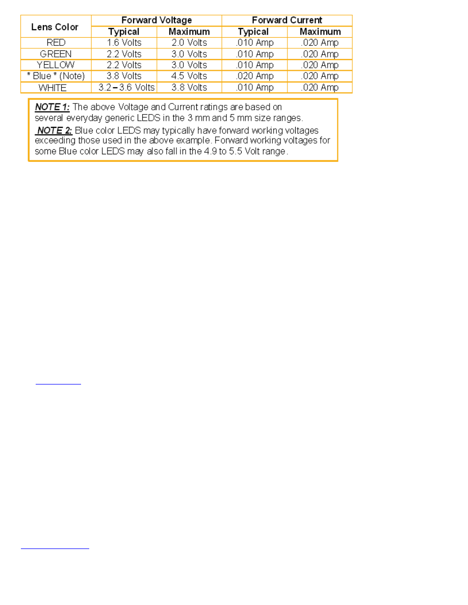
LED VOLTAGE AND CURRENT
LED characteristics are very broad and you have absolutely no idea of any value until you test the
LED.
However here are some of the generally accepted characteristics:
SOLDERING LEDs
LEDs are the most heat-sensitive device of all the components.
When soldering surface-mount LEDs, you should hold the LED with tweezers and "tack" one end.
Then wait for the LED to cool down and solder the other end very quickly. Then wait a few seconds
and completely solder the first end. Check the glow of each LED with 3 cells in series and a 220R
resistor. If you have overheated the LED, its output will be dim, or a slightly different colour, or it
may not work at all. They are extremely sensitive to heat - mainly because the crystal is so close to
the soldering iron.
HIGH-BRIGHT LEDs
LEDs have become more efficient over the past 25 years.
Originally a red LED emitted 17mcd @20mA. These LEDs now emit 1,000mcd to 20,000mcd @20mA.
This means you can lower the current and still produce illumination. Some LEDs operate on a
current as low as 1mA
LEDs as LIGHT DETECTORS
LEDs can also be used to detect light.
Green LEDs are the best, however all LEDs will detect light and produce a voltage equal to the
CHARACTERISTIC VOLTAGE-DROP, providing they receive sufficient light. The current they produce
is miniscule however high-bright and super-bright LEDs produce a higher output due to the fact that
their crystal is more efficient at converting light into electricity.
The
Solar Tracker
project uses this characteristic to track the sun's movement across the sky.
LEDs LEDs LEDs
There are hundreds of circuits that use a LED or drive a LED or flash a LED and nearly all the circuits
in this eBook are different.
Some flash a LED on a 1.5v supply, some use very little current, some flash the LED very brightly
and others use a flashing LED to create the flash-rate.
You will learn something from every circuit. Some are interesting and some are amazing. Some
consist of components called a "building Block" and they can be added to other circuits to create a
larger, more complex, circuit.
This is what this eBook is all about.
It teaches you how to build and design circuits that are fun to see working, yet practical.
You will learn a lot . . . . even from these simple circuits.
Colin Mitchell
TALKING ELECTRONICS.
talking@tpg.com.au
SI NOTATION
All the schematics in this eBook have components that are labelled using the System International

(SI) notation system. The SI system is an easy way to show values without the need for a decimal
point. Sometimes the decimal point is difficult to see and the SI system overcomes this problem and
offers a clear advantage.
Resistor values are in ohms (R), and the multipliers are: k for kilo, M for Mega. Capacitance is
measured in farads (F) and the sub-multiples are u for micro, n for nano, and p for pico. Inductors
are measured in Henrys (H) and the sub-multiples are mH for milliHenry and uH for microHenry.
A 10 ohm resistor would be written as 10R and a 0.001u capacitor as 1n.
The markings on components are written slightly differently to the way they are shown on a circuit
diagram (such as 100p on a circuit and 101 on the capacitor or 10 on a capacitor and 10p on a
diagram) and you will have to look on the internet under Basic Electronics to learn about these
differences.
We have not provided lengthy explanations of how any of the circuits work. This has already been
covered in TALKING ELECTRONICS Basic Electronics Course, and can be obtained on a
CD for $10.00
(posted to anywhere in the world)
For photos of nearly every electronic component, see this website:
https://www.egr.msu.edu/eceshop/Parts_Inventory/totalinventory.php
How good is your power of observation?
Can you find the LED:
POWERING A PROJECT
The safest way to power a project is with a battery. Each circuit requires a voltage from
3v to 12v. This can be supplied from a set of AA cells in a holder or you can also use a
9v battery for some projects.
If you want to power a circuit for a long period of time, you will need a "power supply."
The safest power supply is a Plug Pack (wall-wort, wall wart, wall cube, power brick,
plug-in adapter, adapter block, domestic mains adapter, power adapter, or AC adapter). Some
plug packs have a switchable output voltage: 3v, 6v, 7.5v, 9v, 12v) DC with a current
rating of 500mA. The black lead is negative and the other lead with a white stripe (or a
grey lead with a black stripe) is the positive lead.
This is the safest way to power a project as the insulation (isolation) from the mains is
provided inside the adapter and there is no possibility of getting a shock.
The rating "500mA" is the maximum the Plug Pack will deliver and if your circuit takes
just 50mA, this is the current that will be supplied. Some pluck packs are rated at
300mA or 1A and some have a fixed output voltage. All these plug packs will be
suitable.
Some Plug Packs are marked "12vAC." This type of plug pack is not suitable for these
circuits as it does not have a set of diodes and electrolytic to convert the AC to DC. All
the circuits in this eBook require DC.
PROJECTS
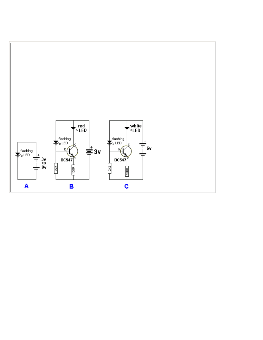
FLASHING A LED
These 7 circuits flash a LED using a supply from 1.5v to 12v.
They all have a different value of efficiency and current consumption. You will find at least one to suit your
requirements.
The simplest way to flash a LED is to buy a FLASHING LED as shown in figure
A
. It will work on 3v to 9v
but it is not very bright - mainly because the LED is not high-efficiency.
A Flashing LED can be used to flash a super-bright red LED, as shown in figure
B
.
Figure
C
shows a flashing LED driving a buffer transistor to flash a white LED. The circuit needs 4.5v -
6v.
Figure
D
produces a very bright flash for a very short period of time - for a red, green, orange or white
LED.
Figure
E
uses 2 transistors to produce a brief flash - for a red, green, orange or white LED.
Figure
F
uses a single cell and a voltage multiplying arrangement to flash a red or green LED.
Figure
G
flashes a white LED on a 3v supply.
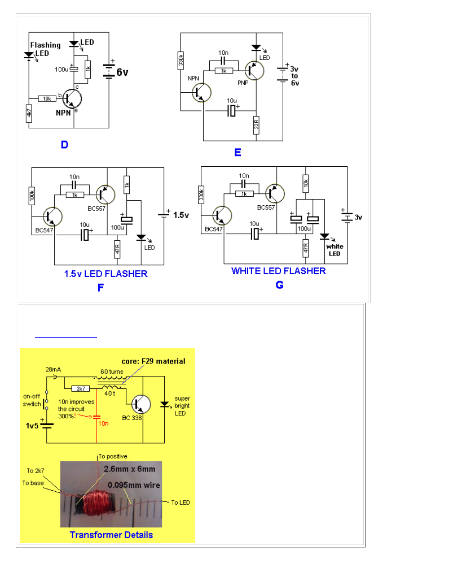
WHITE LED on 1.5v SUPPLY
This circuit will illuminate a white LED using a single cell.
See
LED Torch Circuits
article for more details.
2 WHITE LEDs on 1.5v SUPPLY
This circuit will illuminate two white LEDs using a single cell.
See
LED Torch Circuits
article for more details.
WHITE LED FLASHER
This circuit will flash a white LEDs using a single cell.
See
LED Torch Circuits
article for more details.
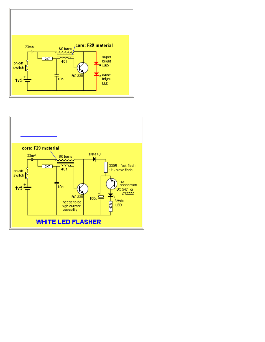
SHAKE TIC TAC
LED TORCH
In the diagram, it looks like the coils sit
on the “table” while the magnet has its
edge on the table. This is just a
diagram to show how the parts are
connected. The coils actually sit flat
against the slide (against the side of
the magnet) as shown in the diagram:
The output voltage depends on how
quickly the magnet passes from one
end of the slide to the other. That's
why a rapid shaking produces a higher
voltage. You must get the end of the
magnet to fully pass though the coil so
the voltage will be a maximum. That’s
why the slide extends past the coils at
the top and bottom of the diagram.
The circuit consists of two 600-turn
coils in series, driving a voltage
doubler. Each coil produces a positive and negative pulse, each time the magnet passes from one end of
the slide to the other.
The positive pulse charges the top electrolytic via the top diode and the negative pulse charges the lower
electrolytic, via the lower diode.
The voltage across each electrolytic is combined to produce a voltage for the white LED. When the
combined voltage is greater than 3.2v, the LED illuminates. The electrolytics help to keep the LED
illuminated while the magnet starts to make another pass.
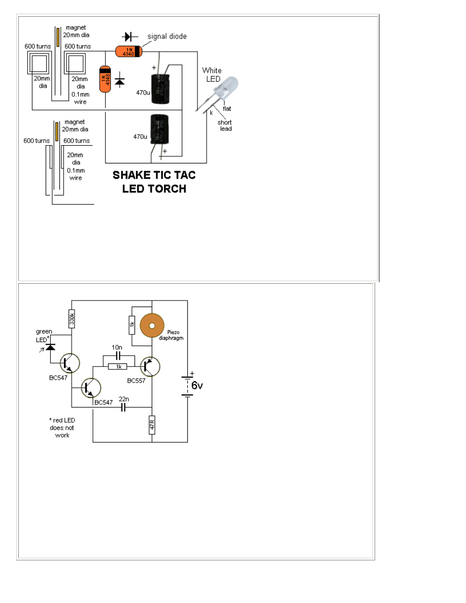
LED DETECTS LIGHT
The LED in this circuit will detect light to turn on the oscillator. Ordinary red LEDs do not work. But
green LEDs, yellow LEDs and high-bright white LEDs and high-bright red LEDs work very well.
The output voltage of the LED is up to 600mV when detecting very bright illumination.
When light is detected by the LED, its resistance decreases and a very small current flows into the base
of the first transistor. The transistor amplifies this current about 200 times and the resistance between
collector and emitter decreases. The 330k resistor on the collector is a current limiting resistor as the
middle transistor only needs a very small current for the circuit to oscillate. If the current is too high, the
circuit will "freeze."
The piezo diaphragm does not contain any active components and relies on the circuit to drive it to
produce the tone.
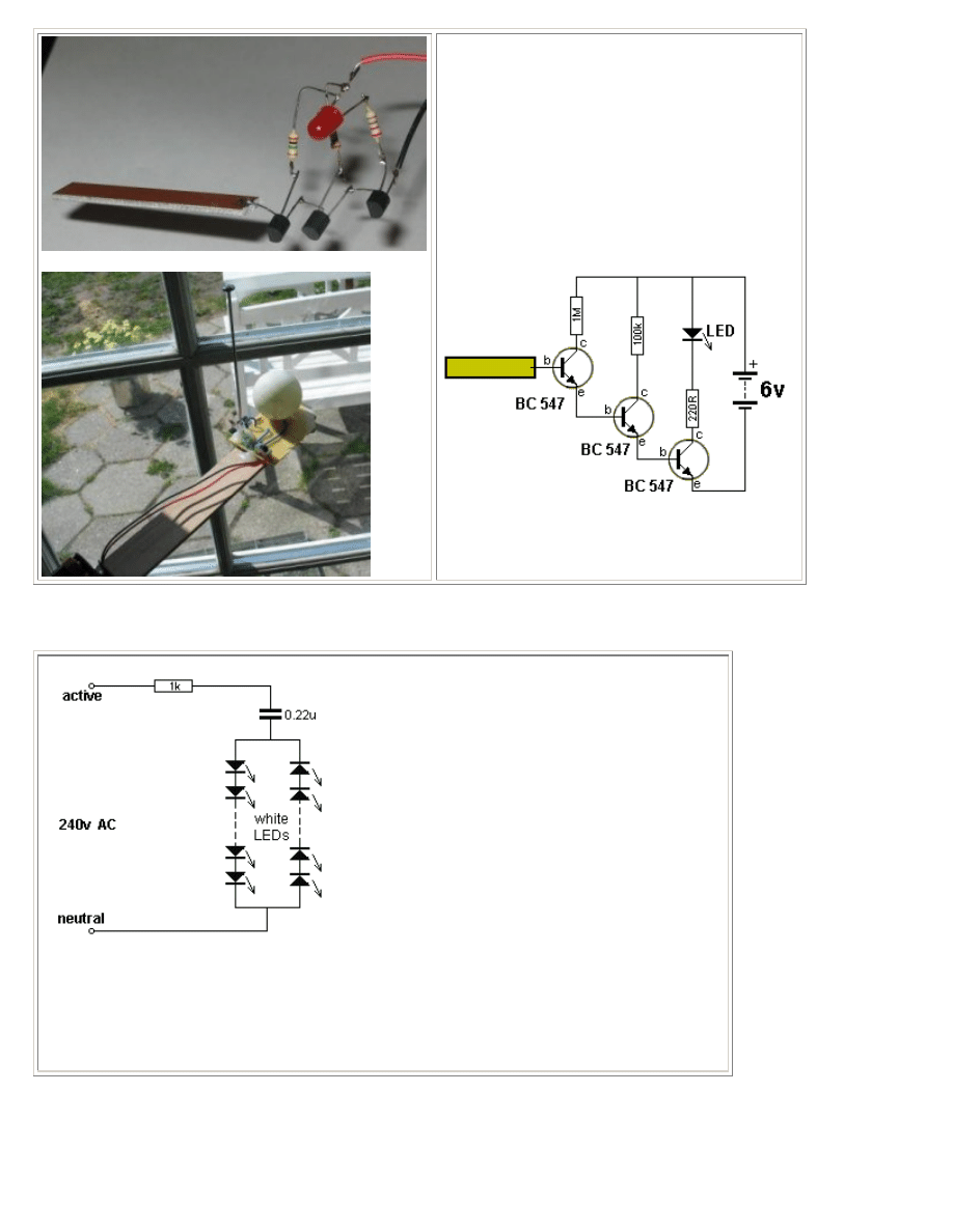
8 MILLION GAIN!
This circuit is so sensitive it will detect "mains
hum." Simply move it across any wall and it will
detect where the mains cable is located. It has a
gain of about 200 x 200 x 200 = 8,000,000 and will
also detect static electricity and the presence of
your hand without any direct contact. You will be
amazed what it detects! There is static electricity
EVERYWHERE! The input of this circuit is
classified as very high impedance.
Here is a photo of the circuit, produced by a
constructor.
LEDs on 240v
I do not like any circuit connected directly to 240v
mains. However Christmas tress lights have been
connected directly to the mains for 30 years without
any major problems.
Insulation must be provided and the lights (LEDs) must
be away from prying fingers.
You need at least 50 LEDs in each string to prevent
them being damaged via a surge through the 1k
resistor - if the circuit is turned on at the peak of the
waveform. As you add more LEDs to each string, the
current will drop a very small amount until eventually,
when you have 90 LEDs in each string, the current will
be zero.
For 50 LEDs in each string, the total characteristic
voltage will be 180v so that the peak voltage will be
330v - 180v = 150v. Each LED will see less than 7mA peak during the half-cycle they are
illuminated. The 1k resistor will drop 7v - since the RMS current is 7mA (7mA x 1,000 ohms = 7v).
No rectifier diodes are needed. The LEDs are the "rectifiers." Very clever. You must have LEDs in
both directions to charge and discharge the capacitor. The resistor is provided to take a heavy
surge current through one of the strings of LEDs if the circuit is switched on when the mains is at a
peak.
This can be as high as 330mA if only 1 LED is used, so
the value of this resistor must be adjusted if a small
number of LEDs are used. The LEDs above detect
peak current.
A 100n cap will deliver 7mA RMS or 10mA peak in
full wave or 3.5mA RMS (10mA peak for half a
cycle) in half-wave. (when only 1 LED is in each
string).
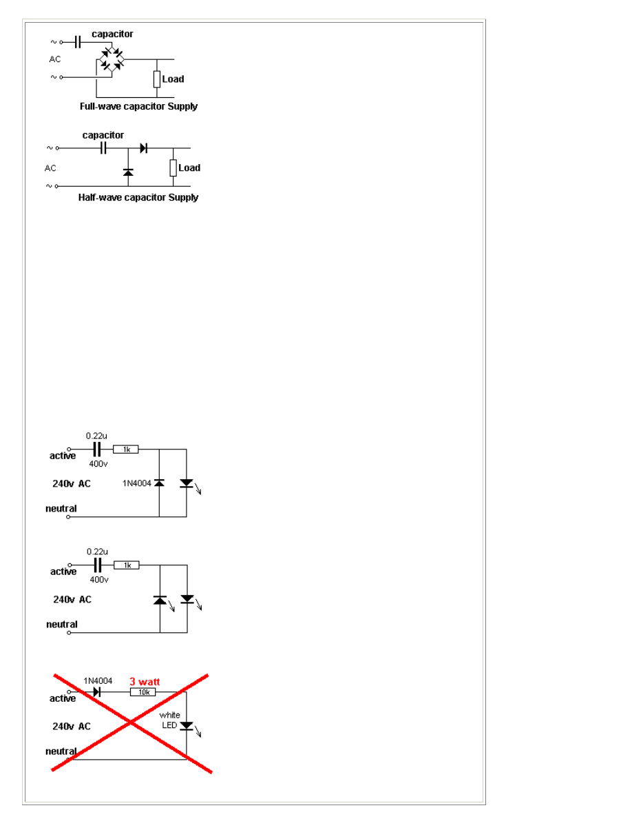
The current-capability of a capacitor needs more
explanation. In the diagram on the left we see a
capacitor feeding a full-wave power supply. This is
exactly the same as the LEDs on 240v circuit above.
Imagine the LOAD resistor is removed. Two of the
diodes will face down and two will face up. This is
exactly the same as the LEDs facing up and facing
down in the circuit above. The only difference is the mid-point is joined. Since the voltage on the
mid-point of one string is the same as the voltage at the mid-point of the other string, the link can
be removed and the circuit will operate the same.
This means each 100n of capacitance will deliver 7mA RMS (10mA peak on each half-cycle).
In the half-wave supply, the capacitor delivers 3.5mA RMS (10mA peak on each half-cycle, but one
half-cycle is lost in the diode) for each 100n to the load, and during the other half-cycle the 10mA
peak is lost in the diode that discharges the capacitor.
You can use any LEDs and try to keep the total voltage-drop in each string equal. Each string is
actually working on DC. It's not constant DC but varying DC. In fact is it zero current for 1/2 cycle
then nothing until the voltage rises above the total characteristic voltage of all the LEDs, then a
gradual increase in current over the remainder of the cycle, then a gradual decrease to zero over
the falling portion of the cycle, then nothing for 1/2 cycle. Because the LEDs turn on and off, you
may observe some flickering and that's why the two strings should be placed together.
SINGLE LED on 240v
A single LED can be illuminated by using a 100n or 220n capacitor with a rating of 400v. These
capacitors are called "X2" and are designed to be connected to the mains.
The LED will be 240v above earth if the
active and neutral are swapped and this
represents a shock of over 340v if anything is
exposed. The power diode in the first
diagram is designed to discharge the 0.22u
during one half of the cycle so that the
capacitor will charge during the other half-
cycle and deliver energy to the LED. The 1k
resistor limits the peak in-rush current when
the circuit is first turned on and the mains
happens to be at a peak.
Two LEDs can be driven from the same
circuit as one LED will be illuminated during
the first half cycle and the other LED will be
driven during the second half of the cycle.
LEDs can also be connected to the mains via
a power diode and current-limiting resistor.
But the wattage lost (dropped) in the resistor
is about 2.5 watts and a 3 watt resistor will be
needed to illuminate a 70mW white LED.
This is an enormous waste of energy and a
capacitor-fed supply shown above is the best
solution.
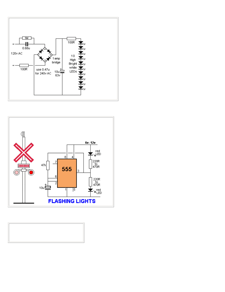
MAINS NIGHT LIGHT
The circuit illuminates a column of 10 white LEDs. The 10u
prevents flicker and the 100R also reduces flicker.
FLASHING RAILROAD LIGHTS
This circuit flashes two red LEDs for a model railway crossing.
LED DIMMER
This circuit will adjust the brightness of one
or more LEDs from 5% to 95%.
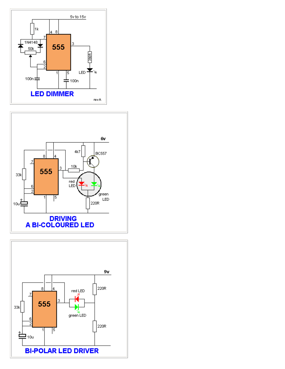
DRIVING A BI-COLOUR LED
Some 3-leaded LEDs produce red and green. This
circuit alternately flashes a red/green bi-coloured LED:
BI-POLAR LED DRIVER
Some 2-leaded LEDs produce red and green. These
are called Bi-polar LEDs. This circuit
alternately flashes a red/green bi-polar LED:
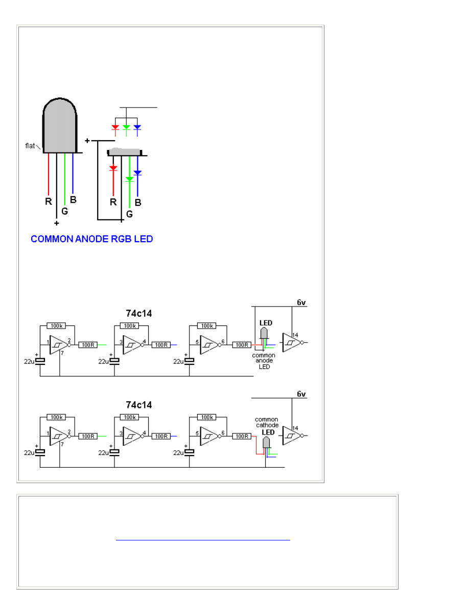
RGB LED DRIVER
This is a simple driver
circuit that drives the 3
LEDs in an RGB LED to
produce a number of
interesting colours. Even
though the component
values are identical in the
three oscillators, the slight
difference in tolerances will
create a random display of
colours and it will take a
while for the pattern to
repeat.
The colours change
abruptly from one colour to
another as the circuit does
not use Pulse Width
Modulation to produce a
gradual fading from one
colour to another.
This LED is called
COMMON ANODE. This
has been done so it can be
connected to transistors or
other devices that "SINK."
The second circuit a
common cathode LED.
Note the different pinout.
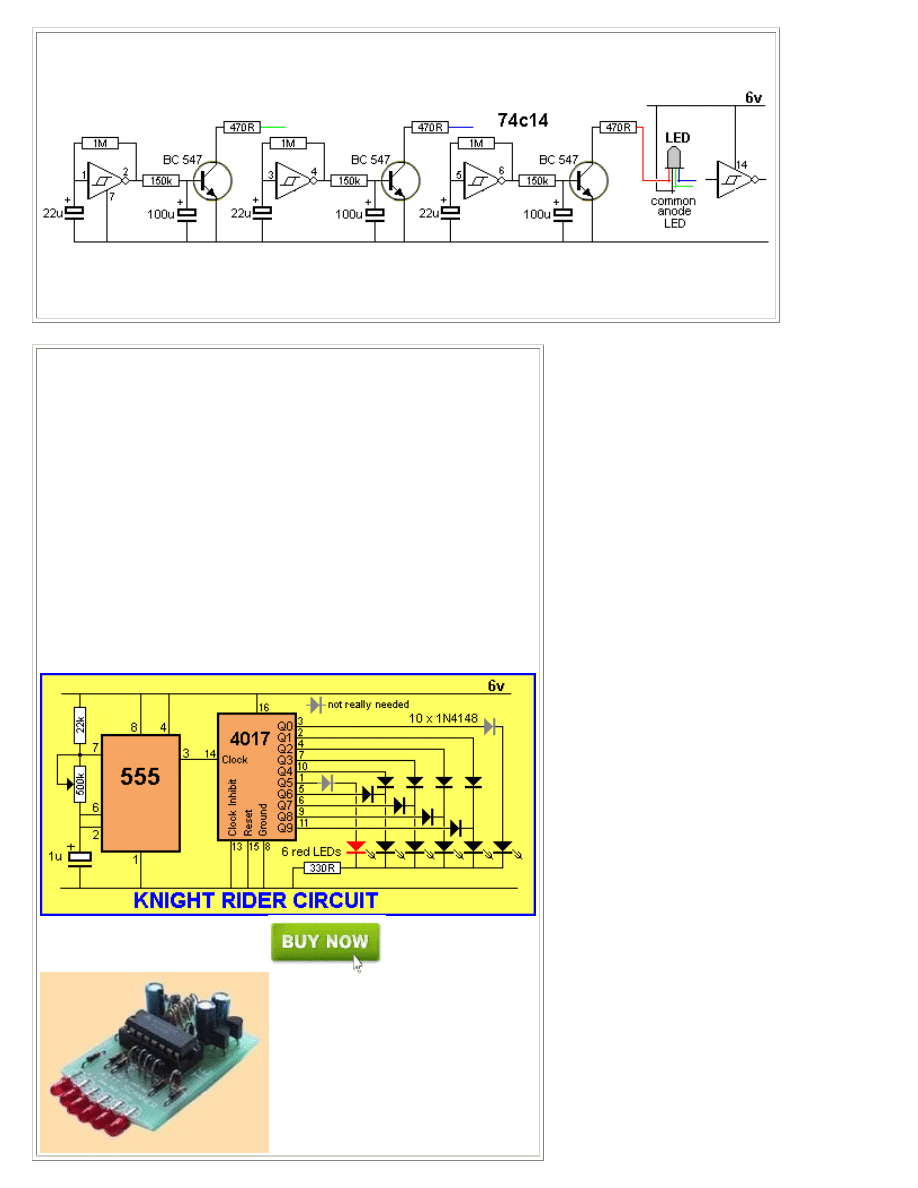
RGB LED FLASHER
This LED flashes at a fast rate then a slow rate. It only requires a current-limiting resistor of 100R for 4.5v to
6v supply or 470R for 7v to 12v supply.
This LED is available from:
http://alan-parekh.vstore.ca/flashing-5000mcd-p-88.html
for 80 cents plus postage.
There are two different types of RGB LEDs. The RGB LED Driver circuit above uses an RGB LED with 4
leads and has 3 coloured chips inside and NOTHING ELSE.
The LED described in the video has 2 leads and requires a dropper resistor so that about 20mA flows. The
LED also contains a microcontroller producing PWM signals. If you cannot get the 2-leaded LED, you can use
a 4-leaded LED plus the circuit below. It is an analogue version of the circuit inside the self-flashing LED, for
the slow-rate:
As with everything Chinese, the self-flashing LED is too gimmicky.
It is better to produce your own colour-change via the circuit above. You can alter the rate by changing the
value of the components and/or remove one or more of the 100u's. The circuit for a common cathode RGB
LED is shown in the RGB LED Driver above.
KNIGHT RIDER
In the Knight Rider circuit, the 555 is wired as an oscillator. It can be
adjusted to give the desired speed for the display. The output of the 555 is
directly connected to the input of a Johnson Counter (CD 4017). The input
of the counter is called the CLOCK line.
The 10 outputs Q
0
to Q
9
become active, one at a time, on the rising edge
of the waveform from the 555. Each output can deliver about 20mA but a
LED should not be connected to the output without a current-limiting
resistor (330R in the circuit above).
The first 6 outputs of the chip are connected directly to the 6 LEDs and
these "move" across the display. The next 4 outputs move the effect in the
opposite direction and the cycle repeats. The animation above shows how
the effect appears on the display.
Using six 3mm LEDs, the display can be placed in the front of a model car
to give a very realistic effect. The same outputs can be taken to driver
transistors to produce a larger version of the display.
The Knight Rider circuit is available as a kit for less
than $15.00 plus postage as Kitt Scanner.
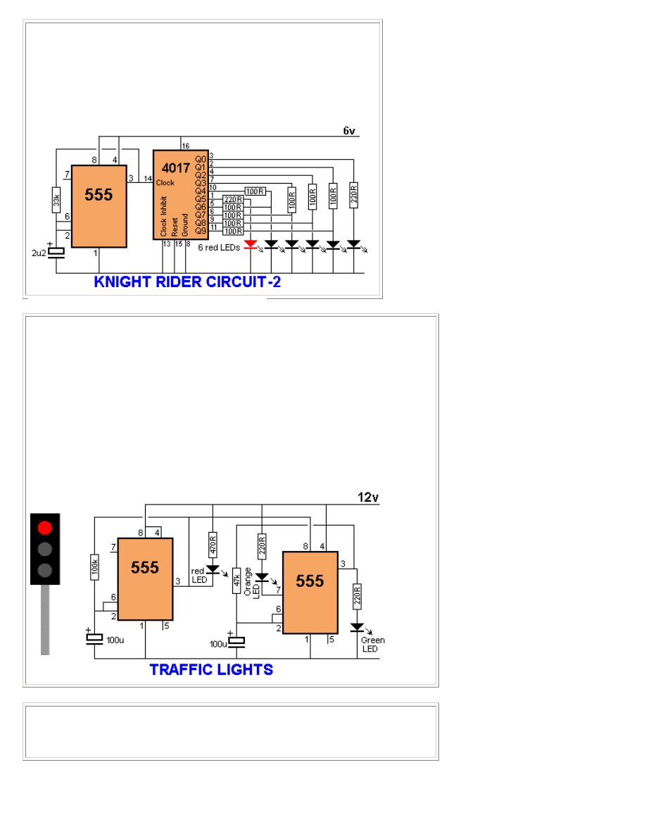
Here is a simple Knight Rider circuit using resistors to drive the LEDs. This
circuit consumes 22mA while only delivering 7mA to each LED. The
outputs are "fighting" each other via the 100R resistors (except outputs Q0
and Q5).
TRAFFIC LIGHTS
Here's a clever circuit using two 555's to produce a set of traffic lights for a model
layout.
The animation shows the lighting sequence and this follows the Australian-standard.
The red LED has an equal on-off period and when it is off, the first 555 delivers power
to the second 555. This illuminates the Green LED and then the second 555 changes
state to turn off the Green LED and turn on the Orange LED for a short period of time
before the first 555 changes state to turn off the second 555 and turn on the red LED.
A supply voltage of 9v to 12v is needed because the second 555 receives a supply of
about 2v less than rail. This circuit also shows how to connect LEDs high and low to a
555 and also turn off the 555 by controlling the supply to pin 8. Connecting the LEDs
high and low to pin 3 will not work and since pin 7 is in phase with pin 3, it can be used
to advantage in this design.
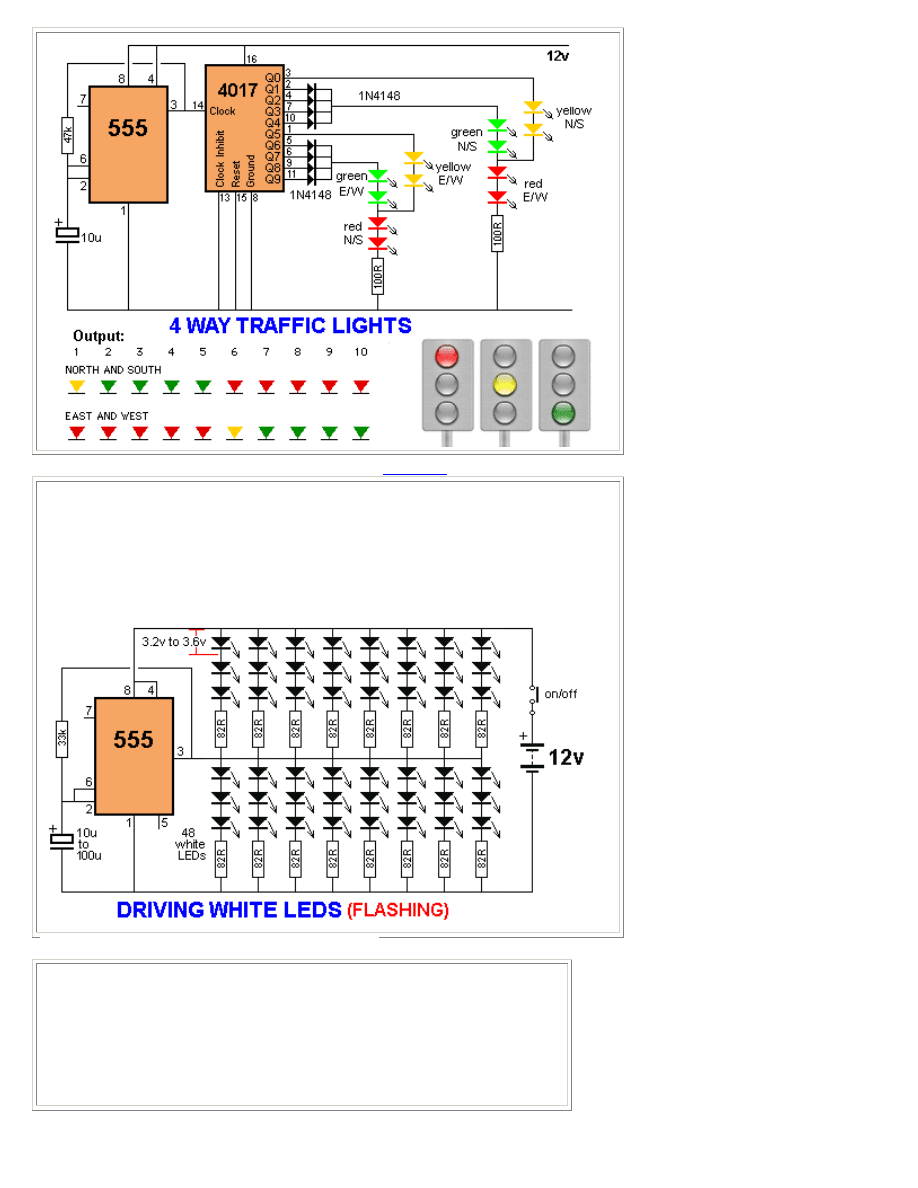
4 WAY TRAFFIC LIGHTS
This circuit produces traffic lights for a "4-way" intersection. The seemingly complex
wiring to illuminate the lights is shown to be very simple.
to Index
DRIVING MANY LEDS
The 555 is capable of sinking and sourcing up to 200mA, but it gets very hot when
doing this on a 12v supply.
The following circuit shows the maximum number of white LEDs that can be
realistically driven from a 555 and we have limited the total current to about 130mA as
each LED is designed to pass about 17mA to 22mA maximum. A white LED drops a
characteristic 3.2v to 3.6v and this means only 3 LEDs can be placed in series.
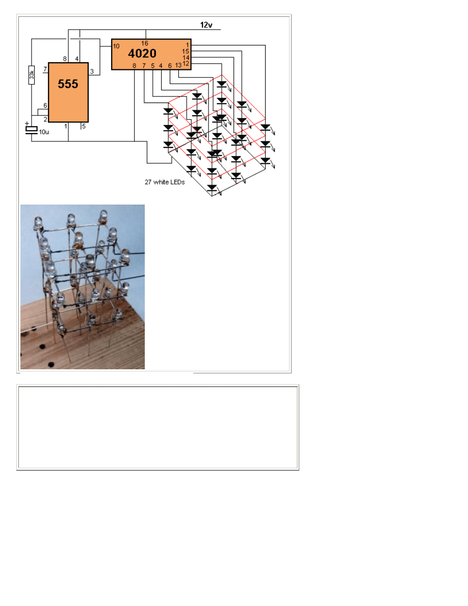
3x3x3 CUBE
This circuit drives a 3x3x3 cube consisting of 27 white LEDs. The 4020 IC is a
14 stage binary counter and we have used 9 outputs. Each output drives 3
white LEDs in series and we have omitted a dropper resistor as the chip can
only deliver a maximum of 15mA per output. The 4020 produces 512 different
patterns before the sequence repeats and you have to build the project to see
the effects it produces on the 3D cube.
UP/DOWN FADING LED
These two circuits make a LED fade on and off. The first circuit charges a 100u
and the transistor amplifies the current entering the 100u and delivers 100 times
this value to the LED via the collector-emitter pins. The circuit needs 9v for
operation since pin 2 of the 555 detects 2/3Vcc before changing the state of the
output so we only have a maximum of 5.5v via a 220R resistor to illuminate the
LED. The second circuit requires a very high value electrolytic to produce the
same effect.
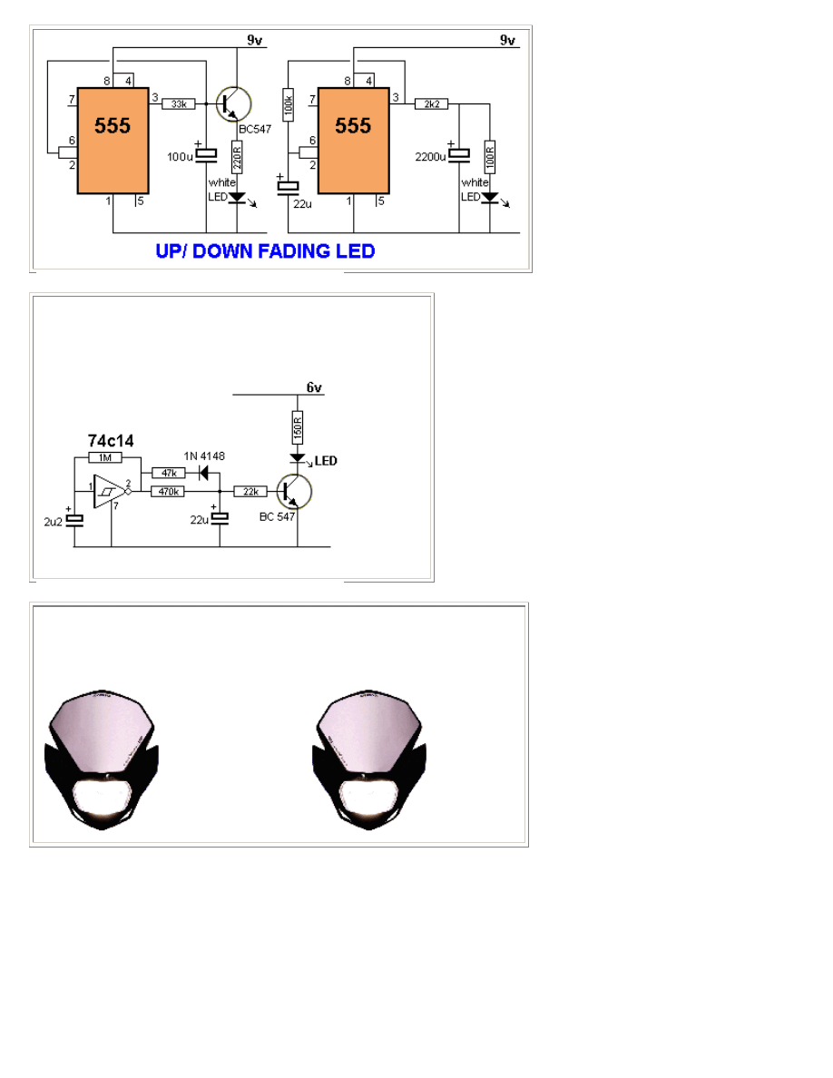
UP/DOWN FADING LED-2
The circuit fades the LED ON and OFF at an equal rate. The
470k charging and 47k discharging resistors have been chosen
to create equal on and off times.
BIKE TURNING SIGNAL
This circuit can be used to indicate left and right turn on a motor-bike. Two
identical circuits will be needed, one for left and one for right.
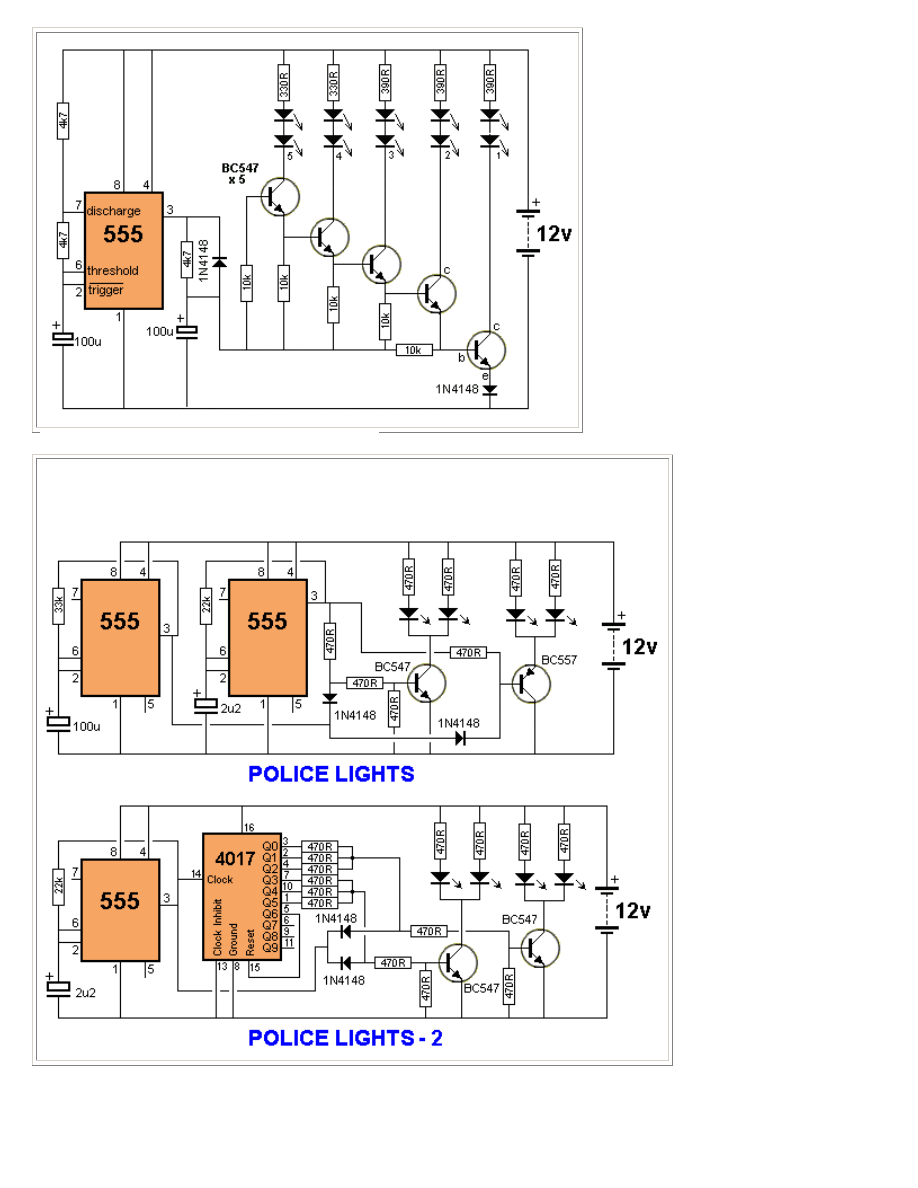
POLICE LIGHTS
These three circuits flash the left LEDs 3 times then the right LEDs 3 times, then repeats. The
only difference is the choice of chips.
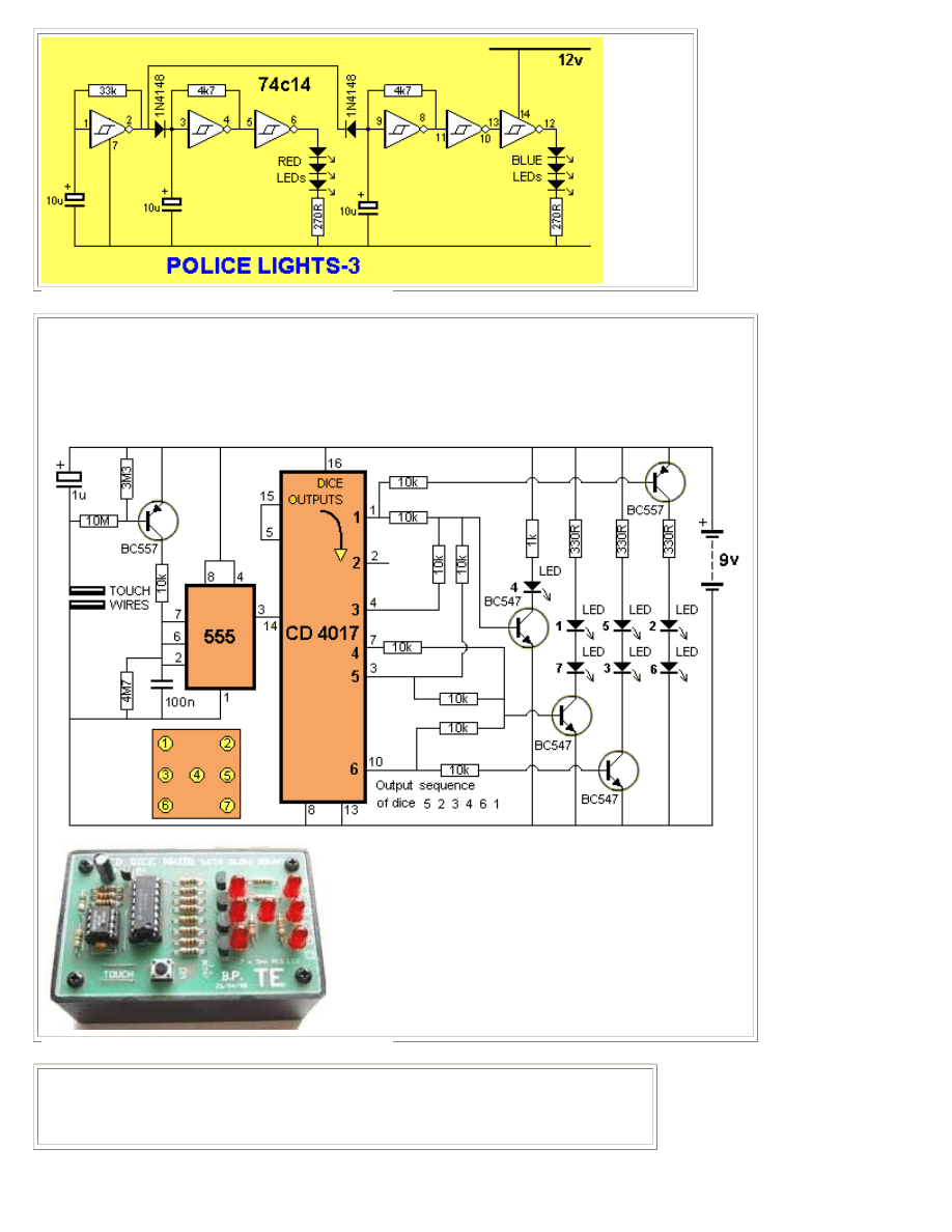
LED DICE with Slow Down
This circuit produces a random number from 1 to 6 on LEDs that are similar to the pips on the side of a
dice. When the two TOUCH WIRES are touched with a finger, the LEDs flash very quickly and when
the finger is removed, they gradually slow down and come to a stop. LED Dice with Slow Down kit is
available from Talking Electronics.
The LED Dice with Slow Down kit is
available for $16.00 plus $6.50
postage.
The kit includes the parts and PC
board.
ROULETTE
This circuit creates a rotating LED that starts very fast when a finger touches the
TOUCH WIRES. When the finger is removed, the rotation slows down and finally stops.
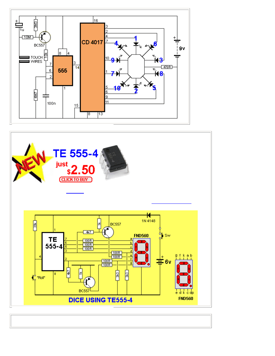
DICE TE555-4
This circuit uses the latest
TE555-4
DICE chip from Talking Electronics. This 8-pin chip is
available for $2.50 and drives a 7-Segment display. The circuit can be assembled on proto-type
board. For more help on the list of components, email Colin Mitchell:
talking@tpg.com.au
LED FX TE555-5
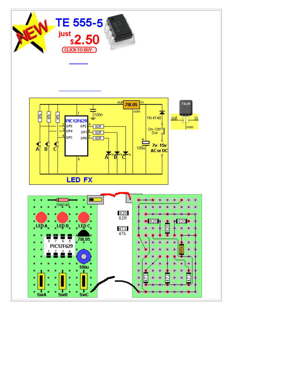
This circuit uses the latest
TE555-5
LED FX chip from Talking Electronics. This 8-pin chip is
available for $2.50 and drives 3 LEDs. The circuit can be assembled on matrix board.
The circuit produces 12 different sequences including flashing, chasing, police lights and flicker.
It also has a feature where you can create your own sequence and it will show each time the chip
is turned on. The kit of components and matrix board can be purchased for $15.00 plus postage.
Email Colin Mitchell:
talking@tpg.com.au
for more details.
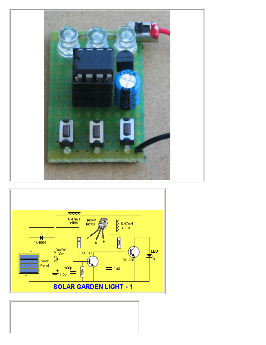
SOLAR GARDEN LIGHT
This is the circuit in a $2.00 Solar Garden Light.
The circuit illuminates a white LED from a 1.2v rechargeable cell.
SOLAR TRACKER
This circuit is a SOLAR TRACKER. It uses green LEDs to detect
the sun and an H-Bridge to drive the motor. A green LED
produces nearly 1v but only a fraction of a milliamp when sunlight
is detected by the crystal inside the LED and this creates an
imbalance in the circuit to drive the motor either clockwise or
anticlockwise. The circuit will deliver about 300mA to the motor.
The circuit was designed by RedRok and kits for the Solar
Tracker are available from:
http://www.redrok.com/electron.htm#tracker
This design is
called:
LED5S5V Simplified LED low power tracker.
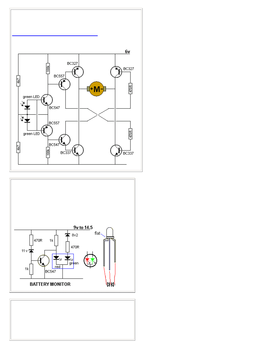
BATTERY MONITOR MkI
A very simple battery monitor can be made with a dual-colour
LED and a few surrounding components. The LED produces
orange when the red and green LEDs are illuminated.
The following circuit turns on the red LED below 10.5v
The orange LED illuminates between 10.5v and 11.6v.
The green LED illuminates above 11.6v
BATTERY MONITOR MkII
This battery monitor circuit uses 3 separate LEDs.
The red LED turns on from 6v to below 11v.
It turns off above 11v and
The orange LED illuminates between 11v and 13v.
It turns off above 13v and
The green LED illuminates above 13v
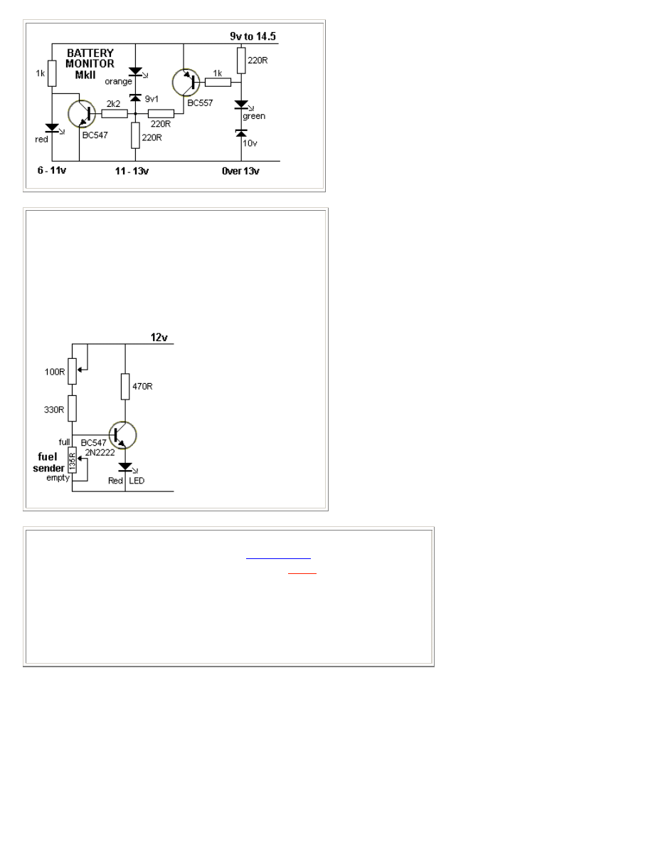
LOW FUEL INDICATOR
This circuit has been designed from a request by a reader. He
wanted a low fuel indicator for his motorbike. The LED
illuminates when the fuel gauge is 90 ohms. The tank is
empty at 135 ohms and full at zero ohms. To adapt the circuit
for an 80 ohm fuel sender, simply reduce the 330R to 150R.
(The first thing you have to do is measure the resistance of
the sender when the tank is amply.)
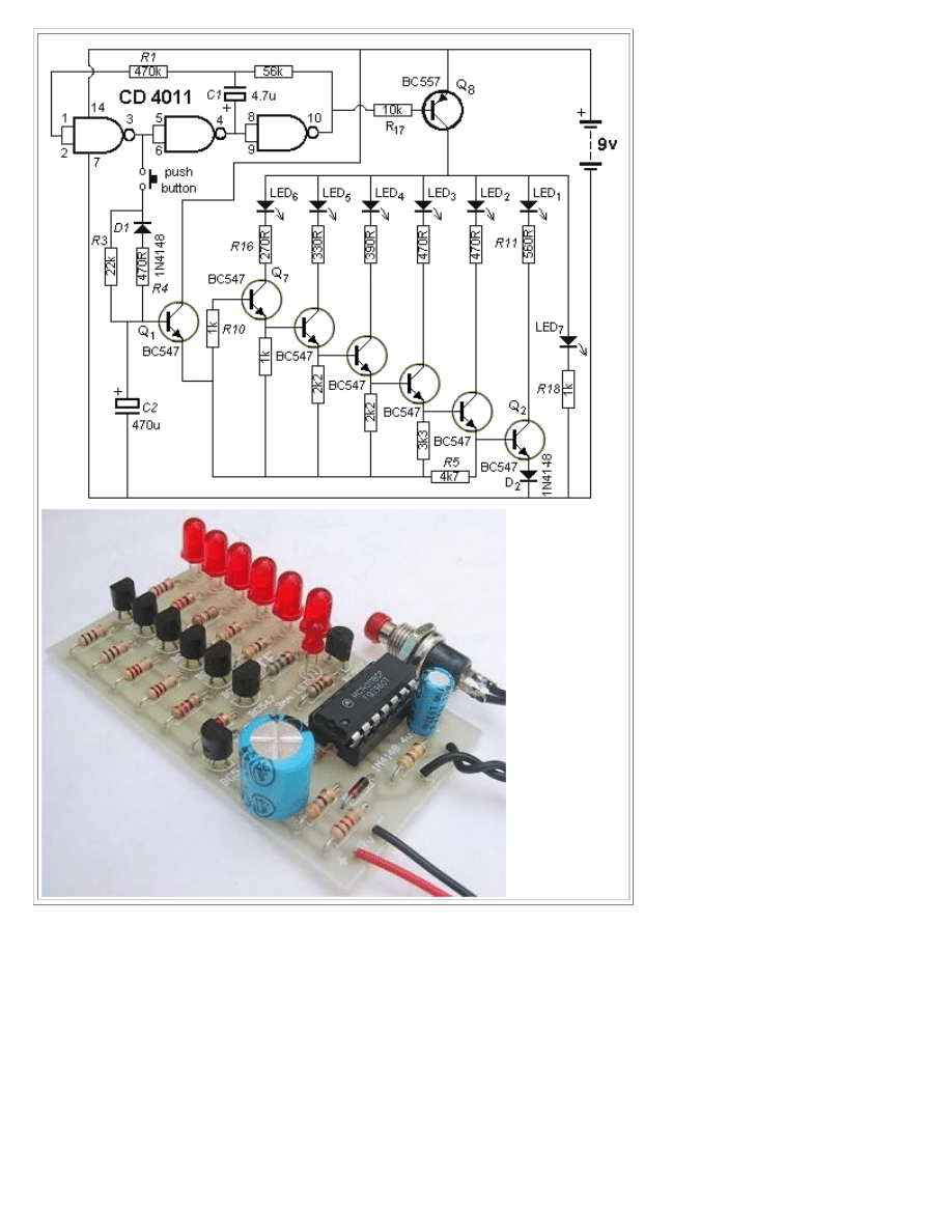
LED ZEPPELIN
This circuit is a game of skill. See full article:
LED Zeppelin
. The kit is available
from talking electronics for $15.50 plus postage. Email
HERE
for details.
The game consists of six LEDs and an indicator LED that flashes at a rate of about 2
cycles per second. A push button is the "Operations Control" and by carefully
pushing the button in synchronisation with the flashing LED, the row of LEDs will
gradually light up.
But the slightest mistake will immediately extinguish one, two or three LEDs. The
aim of the game is to illuminate the 6 LEDs with the least number of pushes.
We have sold thousands of these kits. It's a great challenge.
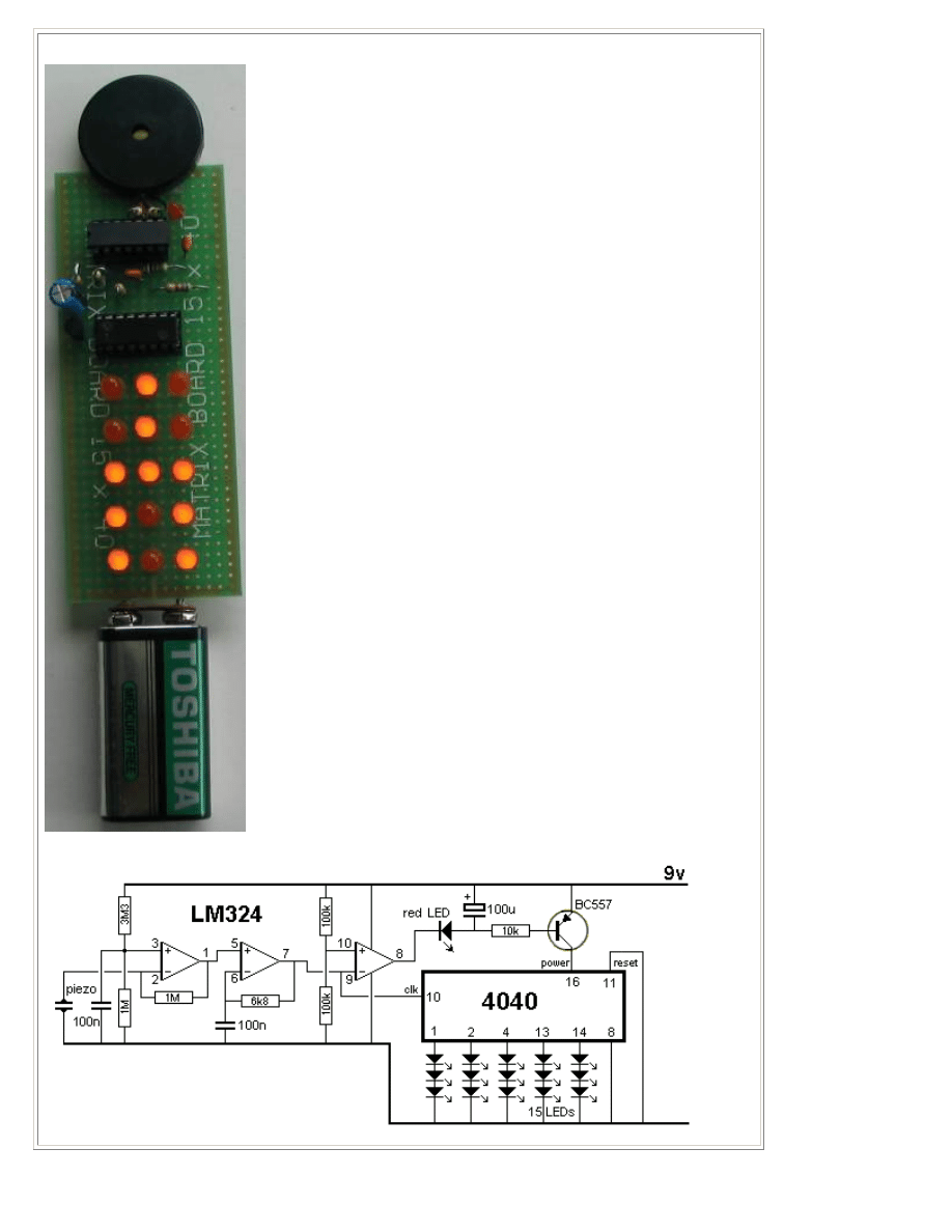
THE DOMINO EFFECT
Here's a project with an interesting name. The original design was
bought over 40yearsa ago, before the introduction of the electret
microphone. They used a crystal earpiece.
We have substituted it with a piezo diaphragm and used a quad op-
amp to produce two building blocks. The first is a high-gain amplifier
to take the few millivolts output of the piezo and amplify it
sufficiently to drive the input of a counter chip. This requires a
waveform of at least 6v for a 9v supply and we need a gain of about
600.
The other building block is simply a buffer that takes the high-
amplitude waveform and delivers the negative excursions to a
reservoir capacitor (100u electrolytic). The charge on this capacitor
turns on a BC557 transistor and this effectively takes the power pin
of the counter-chip to the positive rail via the collector lead.
The chip has internal current limiting and some of the outputs are
taken to sets of three LEDs.
The chip is actually a counter or divider and the frequency picked
up by the piezo is divided by 128 and delivered to one output and
divided by over 8,000 by the highest-division output to three more
LEDs The other lines have lower divisions.
This creates a very impressive effect as the LEDs are connected to
produce a balanced display that changes according to the beat of
the music.
The voltage on the three amplifiers is determined by the 3M3 and
1M voltage-divider on the first op-amp. It produces about 2v. This
makes the output go HIGH and it takes pin 2 with it until this pin see
a few millivolts above pin3. At this point the output stops rising.
Any waveform (voltage) produced by the piezo that is lower than the
voltage on pin 3 will make the output go HIGH and this is how we
get a large waveform.
This signal is passed to the second op-amp and because the
voltage on pin 6 is delayed slightly by the 100n capacitor, is also
produces a gain.
When no signal is picked up by the piezo, pin 7 is approx 2v and pin
10 is about 4.5v. Because pin 9 is lower than pin 10, the output pin
8 is about 7.7v (1.3v below the supply rail) as this is as high as the
output will go - it does not go full rail-to-rail.
The LED connected to the output removes 1.7v, plus 0.6v between
base and emitter and this means the transistor is not turned on.
Any colour LEDs can be used and a mixture will give a different
effect.
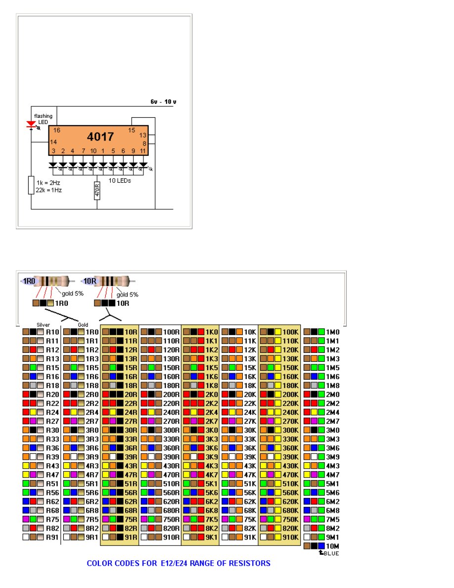
10 LED CHASER
Here's an interesting circuit that creates a clock
pulse for a 4017 from a flashing LED. The flashing
LED takes almost no current between flashes and
thus the clock line is low via the 1k to 22k resistor.
When the LED flashes, the voltage on the clock
line is about 2v -3v below the rail voltage
(depending on the value of the resistor) and this is
sufficient for the chip to see a HIGH.
(circuit designed on 9-10-2010)
If 3rd band is gold, Divide by 10
If 3rd band is silver, Divide by 100
(to get 0.22ohms etc)
Not copyright 20-5-2011 Colin Mitchell You can copy and use anything.
Wyszukiwarka
Podobne podstrony:
30 LED Projects
Origami 30 fold by fold projects
Origami 30 fold by fold projects
Origami 30 fold by fold projects
30 Struktury zaleznosci miedzy wskaznikami zrow rozw K Chmura
30 Wydatki rodziny
30 Tydzień zwykły, 30 środa
Fizyka 0 wyklad organizacyjny Informatyka Wrzesien 30 2012
geolog ogolna 30
Ustawa z 30 10 2002 r o ubezp społ z tyt wyp przy pracy i chor zawod
30 Obciążenia obiektów budowlanych, mostów drogowych i kolejowych
wyklad 29 i 30 tech bad
wyklad z kardiologii 30 11 2011
Prezentacja ZPR MS Project
więcej podobnych podstron