Sheet Metal Work
GENERAL INFORMATION
LOWER STRUCTURE
UPPER REAR STRUCTURE
TOP OF BODY
77 11 292 482
"The repair methods given by the manufacturer in this document are based on the
technical specifications current when it was prepared.
The methods may be modified as a result of changes introduced by the manufacturer
in the production of the various component units and accessories from which his
vehicles are constructed."
JANUARY 2000
All copyrights reserved by Renault.
EDITION ANGLAISE
Copying or translating, in part or in full, of this document or use of the service part
reference numbering system is forbidden without the prior written authority of Renault.
© RENAULT 2000
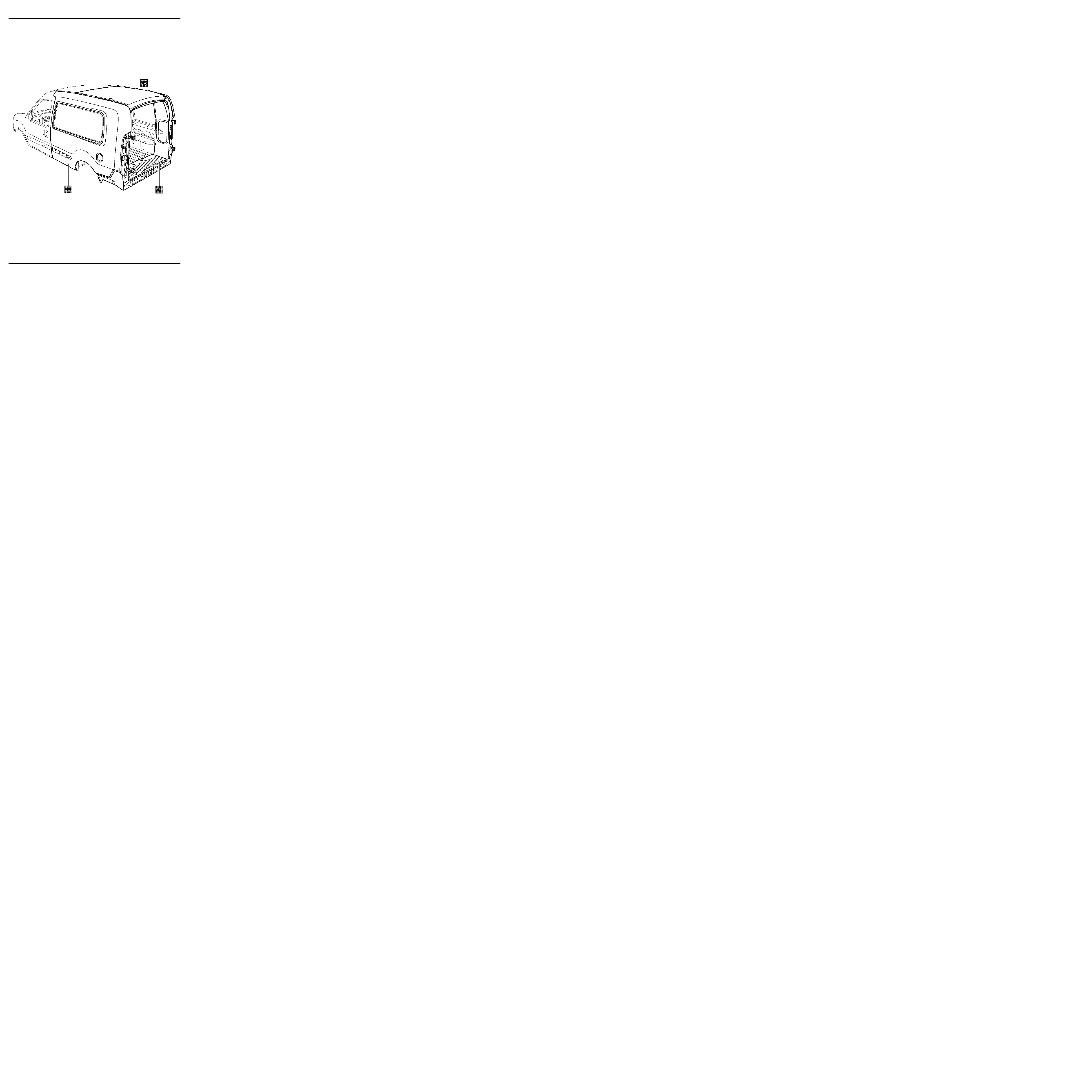
EXPLODED VIEW
Sheet Metal Work
Contents
Page
40
41
44
45
GENERAL INFORMATION
Dimensions
40-1
Engine and equipment
40-2
Towing
40-3
Key to symbols
40-4
Fitting the extension elements
40-5
Description of parts
40-6
Sub-frame dimensions
40-8
Repair bench
40-9
Tools and specific products
40-12
LOWER STRUCTURE
Semi-extreme rear cross member
41-1
Rear floor extender
41-8
UPPER REAR STRUCTURE
Basic body rear wing panel
44-1
Added rear wing panel
44-3
Basic body side panel
44-12
Added side panel
44-14
Side panel extender
44-24
Side inner panel extender
44-28
Upper rear corner stiffener
44-30
Lights mounting side panel rain channel 44-33
TOP OF BODY
Grand volume added roof
45-1
Roof inner panel extender
45-5
P
X
A
Aa
B
Bb
G
I
J
K
Aa
E
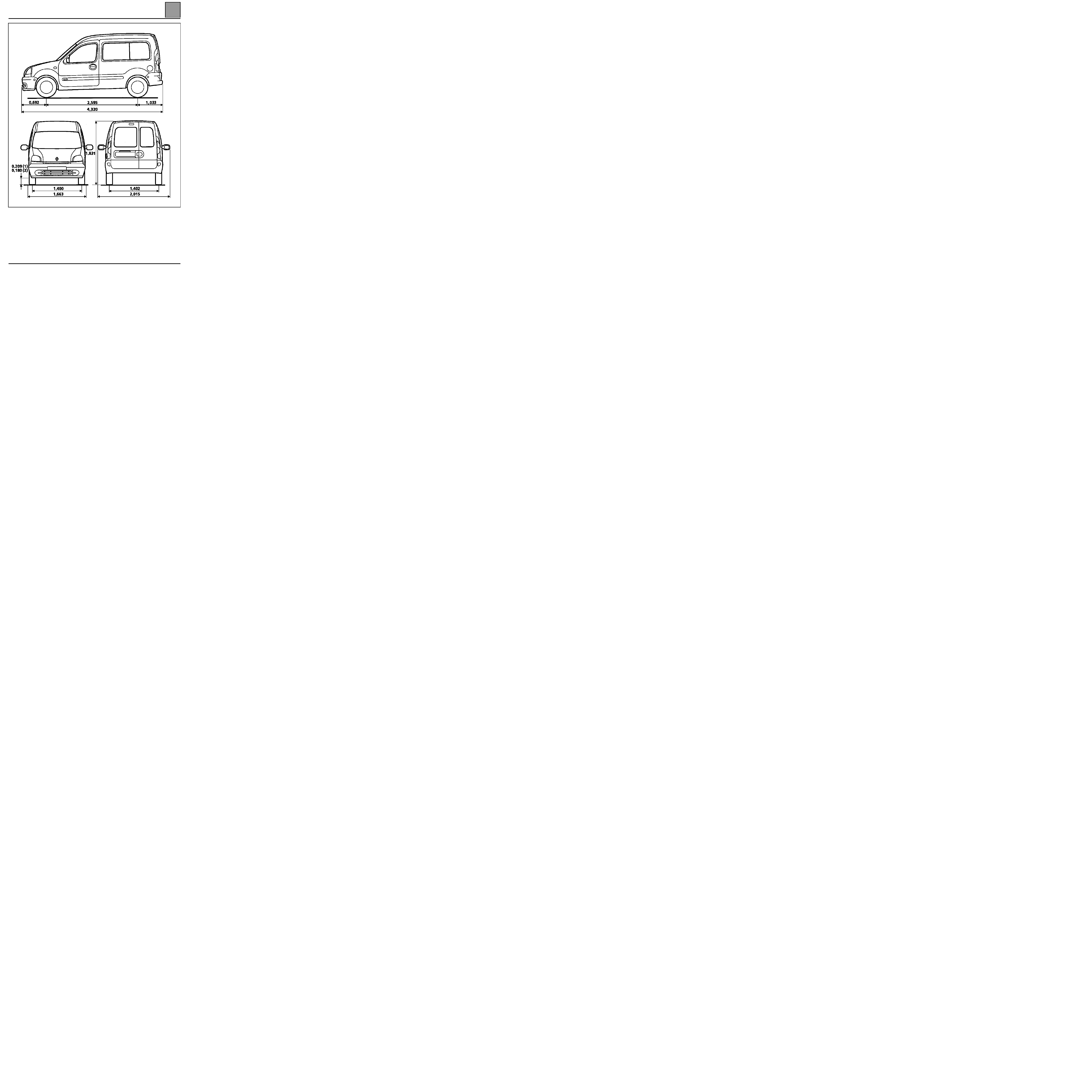
GENERAL INFORMATION
Dimensions
40
140
GENERAL INFORMATION
Dimensions
(1) Empty
(2) Laden
Dimensions in metres.
40-1

GENERAL INFORMATION
Engine and equipment
40
Engine and equipment
BODY AND EXTENDED PASSENGER COMPARTMENT
Vehicle type
Engine
Clutch type
Gearbox type
manual and automatic
Type
Capacity
(cm
3
)
FC0HHF
E7J
1390
180 CP 3300
JB3
FC0EHF
F8Q
1870
200 COPV 3250
JB1
BODY
EXTENDED
PASSENGER
COMPARTMENT
Petrol
Diesel
Petrol
Diesel
Pay load (kg)
550
600
580
580
Weight (kg) when empty and ready for operation
(basic vehicle)
1175 1220 1195 1240
Weight (kg) when empty and ready for operation
on front
610 660 610 655
Weight (kg) when empty and ready for operation
on rear
565 560 585 585
Weight (kg) when empty and ready for operation
(all options)
1227 1270 1246 1291
40-2
GENERAL INFORMATION
Towing
40
40-3
Towing
OBSERVE THE LEGAL TOWING REQUIREMENTS OF THE COUNTRY YOU ARE IN.
NEVER USE THE DRIVESHAFTS AS ATTACHMENT POINTS.
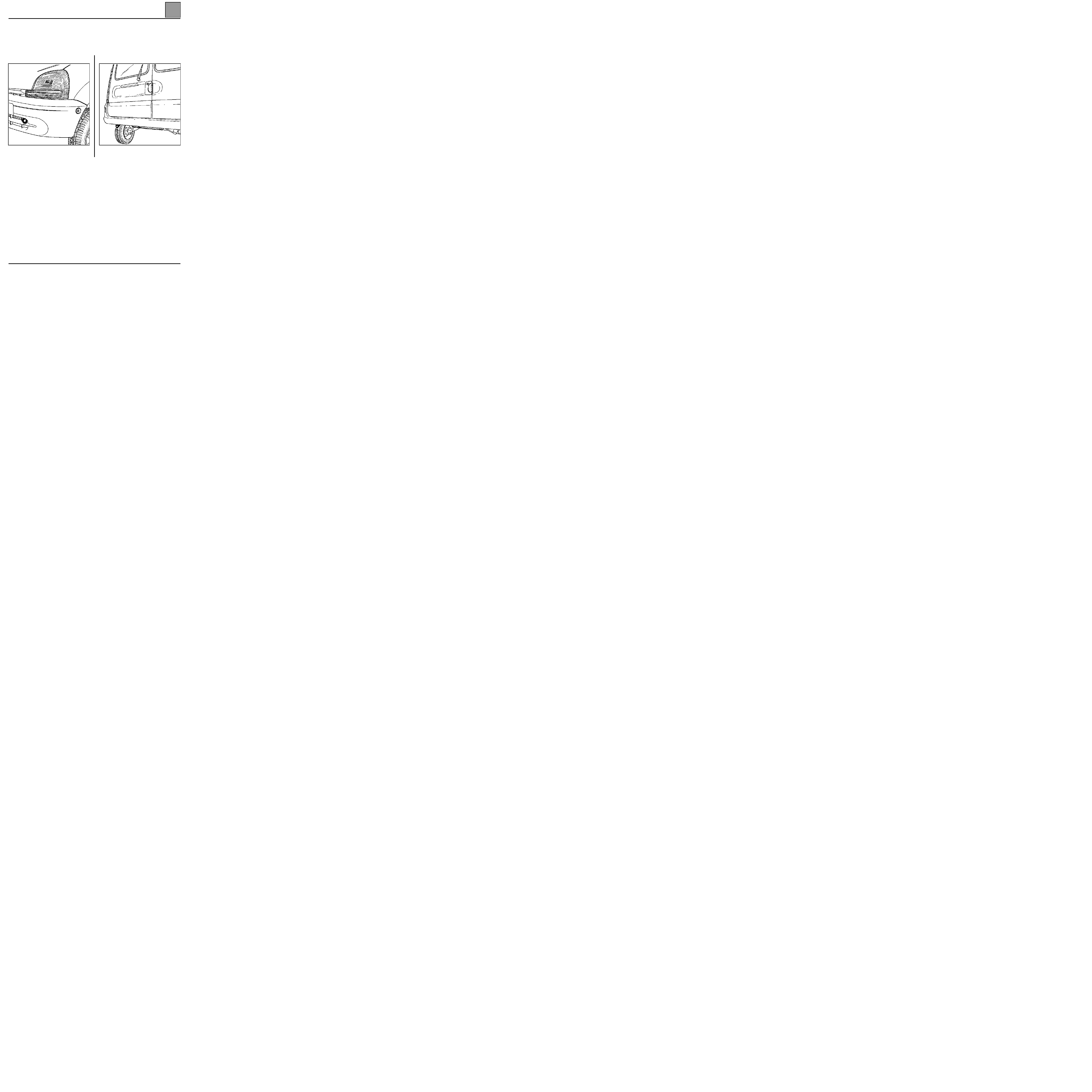
SPECIAL FEATURES OF THE KANGOO GRAND VOLUME
This vehicle does not have a rear towing eye.
FRONT
The towing eye may only be used for towing on the
road.
REAR
Under no circumstances should the rear towing ring of
the basic body be used for towing.
GENERAL INFORMATION
Key to Symbols
40
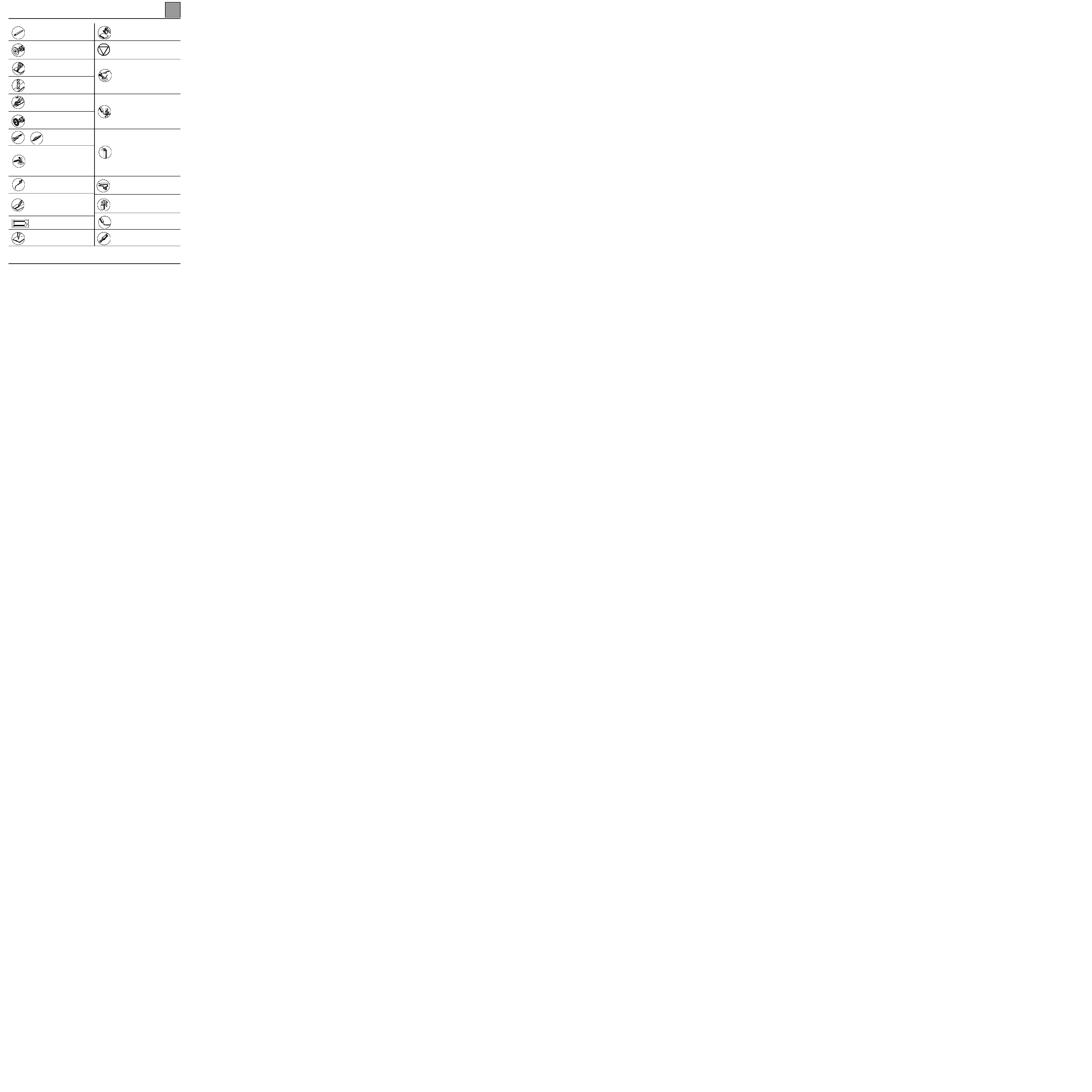
Key to Symbols
Chiselling
Crimping of exterior door panels.
Grind back beads or spot welds.
Straight grinding wheel with 75 mm
diameter bakelite impregnated disc,
thickness 1.8 to 3.2 mm.
Safety symbol.
This means that the welding operation in
question concerns one or more of the
vehicle's vital safety components.
Grind back spot welds.
Straight grinding wheel 20 000 rpm fitted
with a spherical burr Ø 10 or 16 mm.
Body solder - lead fill.
Hot air torch.
Nozzle output temperature 600° min.
Slipper+ 33 % tin solder + tallow.
Note: to a large extent, body solder filling
compensates for the heat distortion
caused by welding.
Drill spot welds.
Hardened steel bit.
Speed of rotation 800 to 1 000 rpm.
Unpicking
Application of weldable mastic.
This mastic is a conductor, interposed
between two spot welding sheets, it
ensures the seal between the sheets and
avoids corrosion of the spot weld
Cleaning surfaces to be welded.
Fibre disc Ø 100 mm
Cutting with a saw.
Pneumatic power hacksaw.
Application of aluminium paint.
This is to be applied to the joint faces of
each of the parts to be plug welded. This
paint is conductive and can withstand high
temperatures; it gives anti-corrosion
protection around welds
– Cut out part by grinding off flange or
grinding back remaining traces of spot
weld.
– Finish surface after welding.
– Angle grinder fitted with a rubber pad
and a 120 to 180 mm diameter fibre disc
grain size P36.
Unsoldering.
Apply a fillet of extruded mastic
●
from a manual or pneumatic spray gun
●
one or two pot mastic for crimped and
butt joints.
MAG stitch weld
Note: to obtain a good quality weld we
recommend the use of a gas consisting of
argon + 15% CO2 which is considered an
active gas (MAG)
Apply mastic by spraying
●
spray gun.
●
anti-chipping and anti-corrosion in two
parts
Apply a bead of extruded adhesive mastic
●
from a manual or pneumatic spray gun
●
adhesive mastic in one or two parts
Resistance spot welding
Plug welding.
Under MAG gas protection.
Thermal cleaning of extruded or spray
mastic
40-4
GENERAL INFORMATION
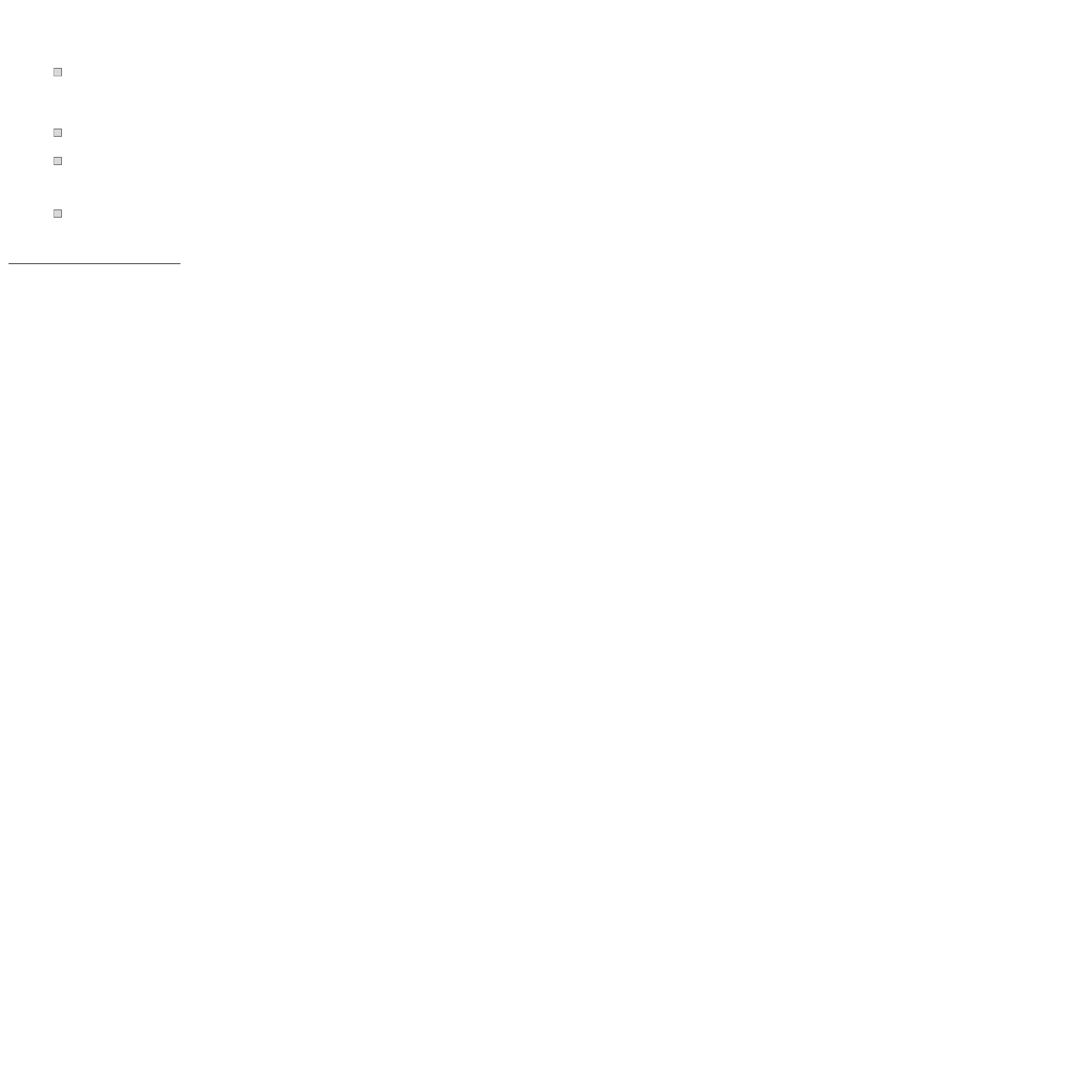
Fitting extension elements
40
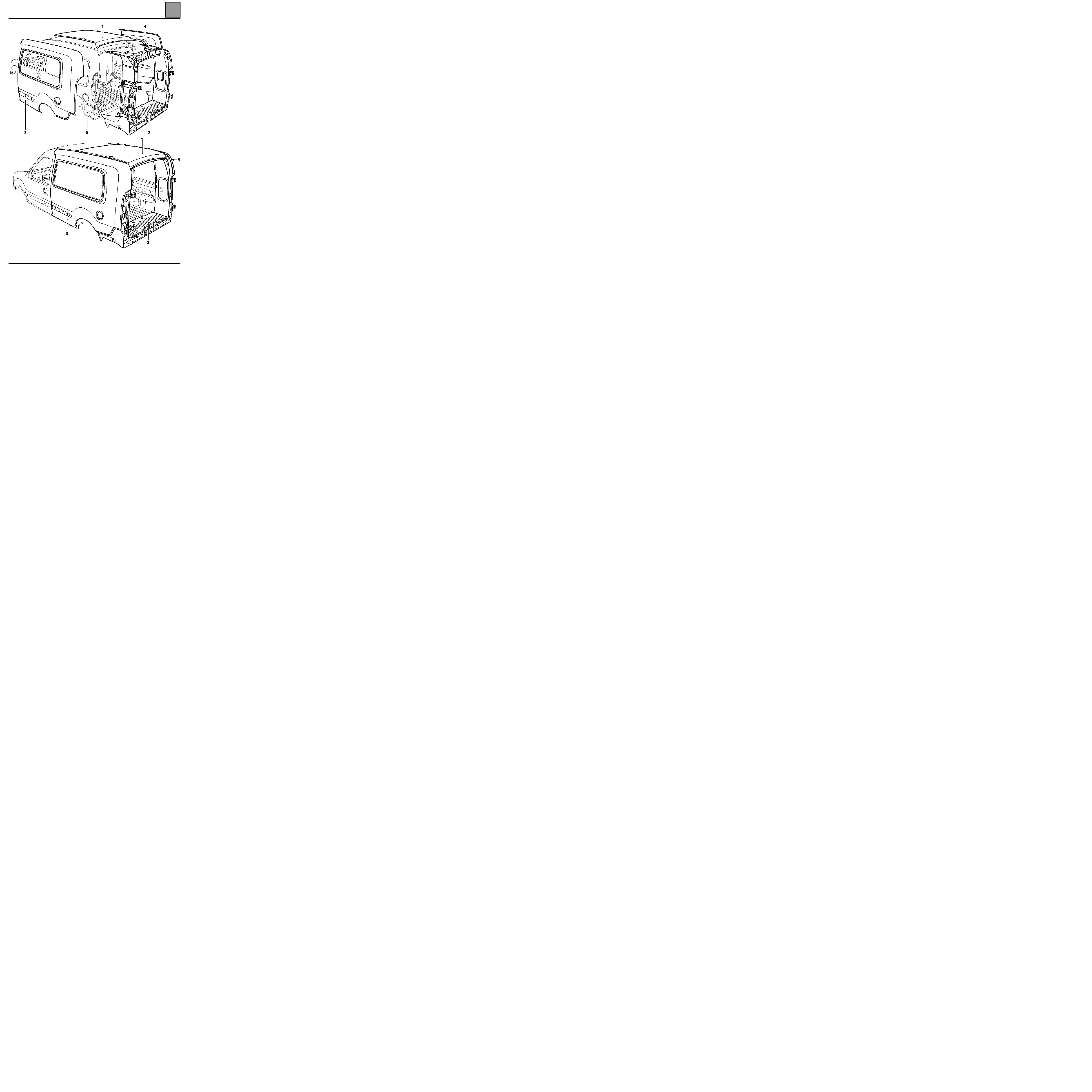
Fitting extension elements
40-5
1
Roof
2
Rear ring
3
Side panel
4
Wing panel
5
Basic body
GENERAL INFORMATION
Description of parts
40
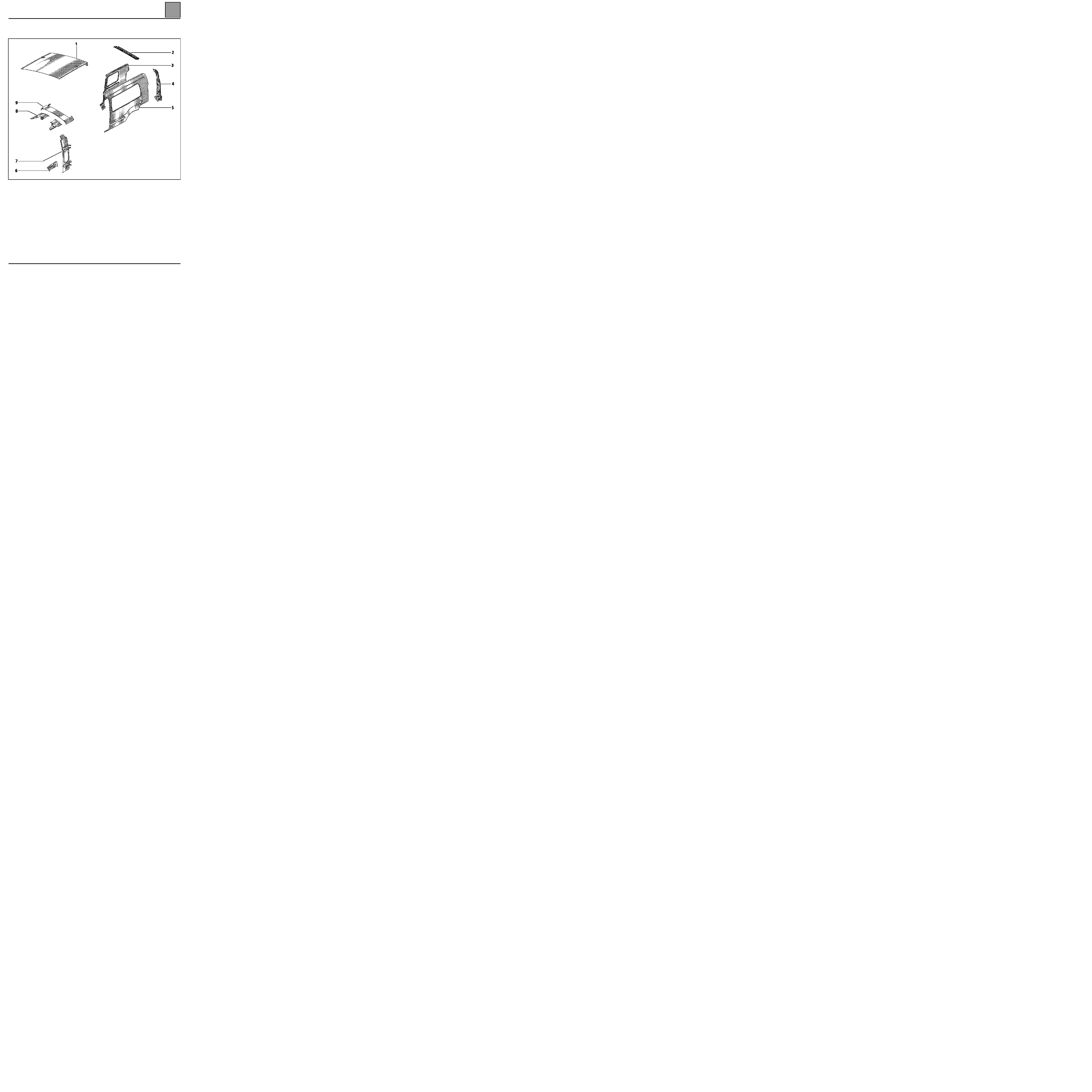
Description of parts
UPPER STRUCTURE
1
Roof added
2
Roof rear cross member
3
Rear wing panel (panel and glazed version)
4
Side panel rain channel support
5
Side panel added (panel and glazed version)
6
Side panel extender
7
Side inner panel extender
8
Upper rear corner stiffener
9
Roof inner panel extender
PRF4011
40-6
GENERAL INFORMATION
Description of parts
40
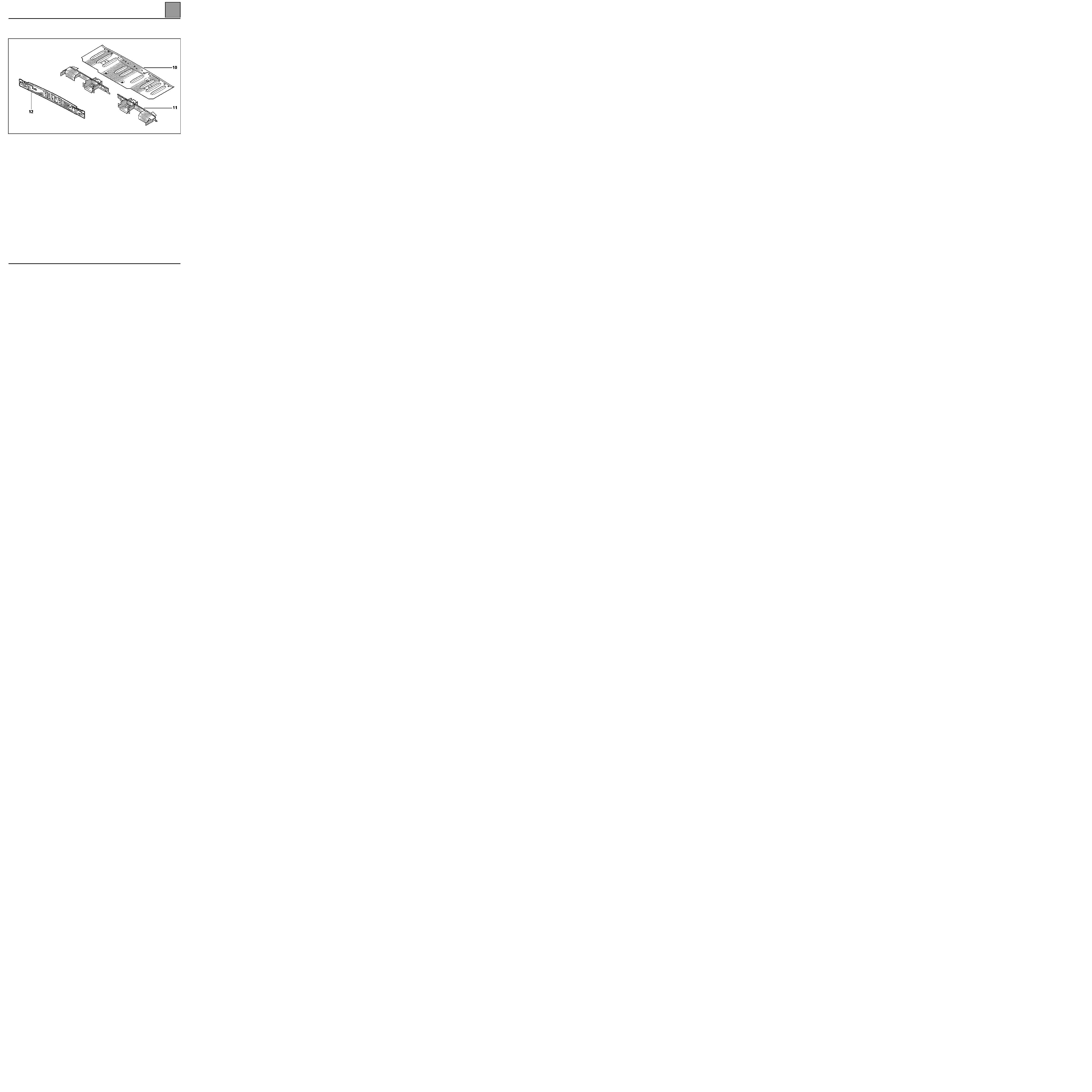
40-7
SUB-FRAME
10 Rear floor extender
11 Demi-rear end cross member
12 Rear end panel
PRF4012

GENERAL INFORMATION
Sub-frame dimensions
40
Sub-frame dimensions
DESCRIPTION
X
Y
Z
DIAMETER
SLOPE %
L
Rear end cross member (end panel)
3 446
- 497.5
151
M8
0
40-8
GENERAL INFORMATION
Repair Bench
40
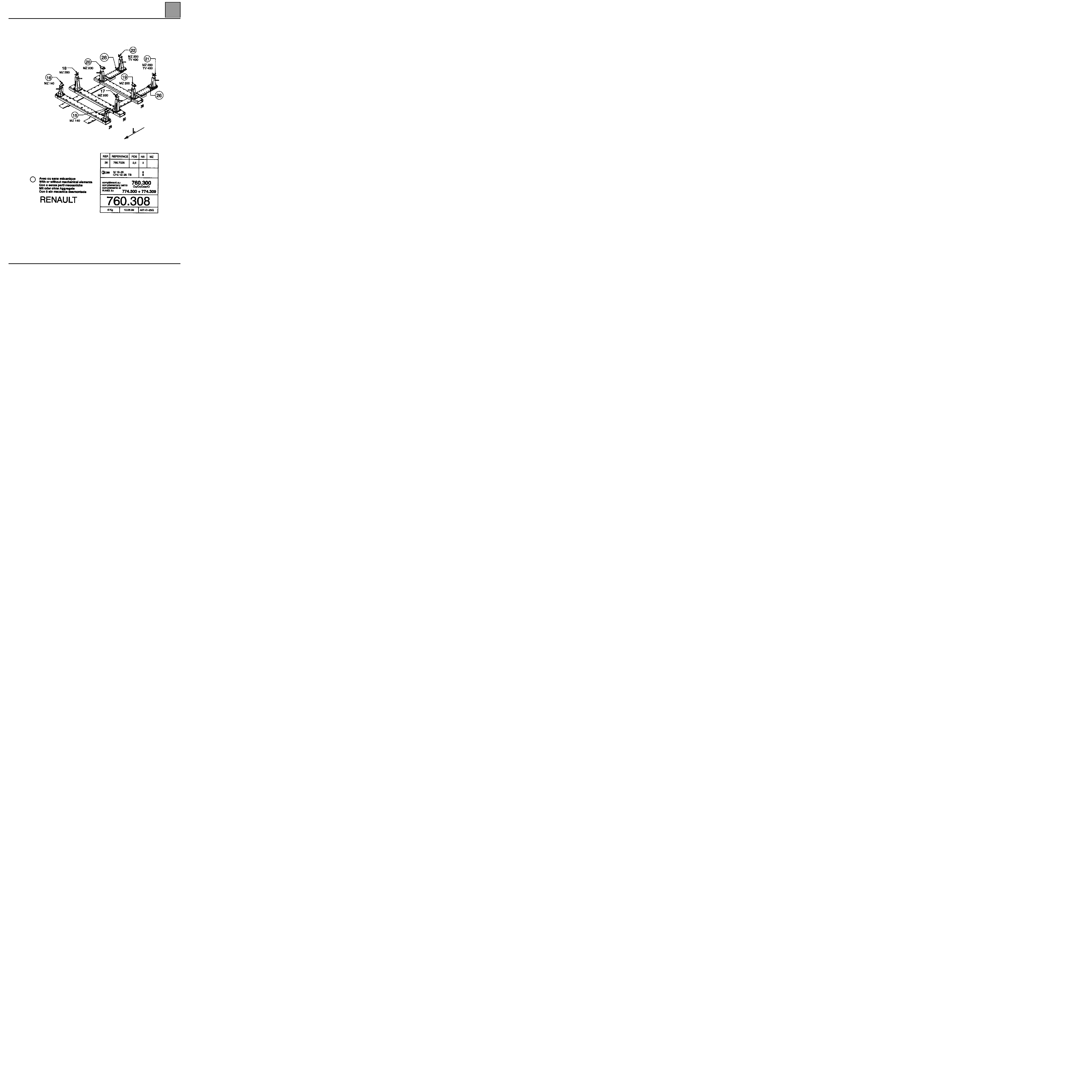
Repair Bench
CELETTE REPAIR BENCH
40-9
GENERAL INFORMATION
Repair Bench
40
40-10
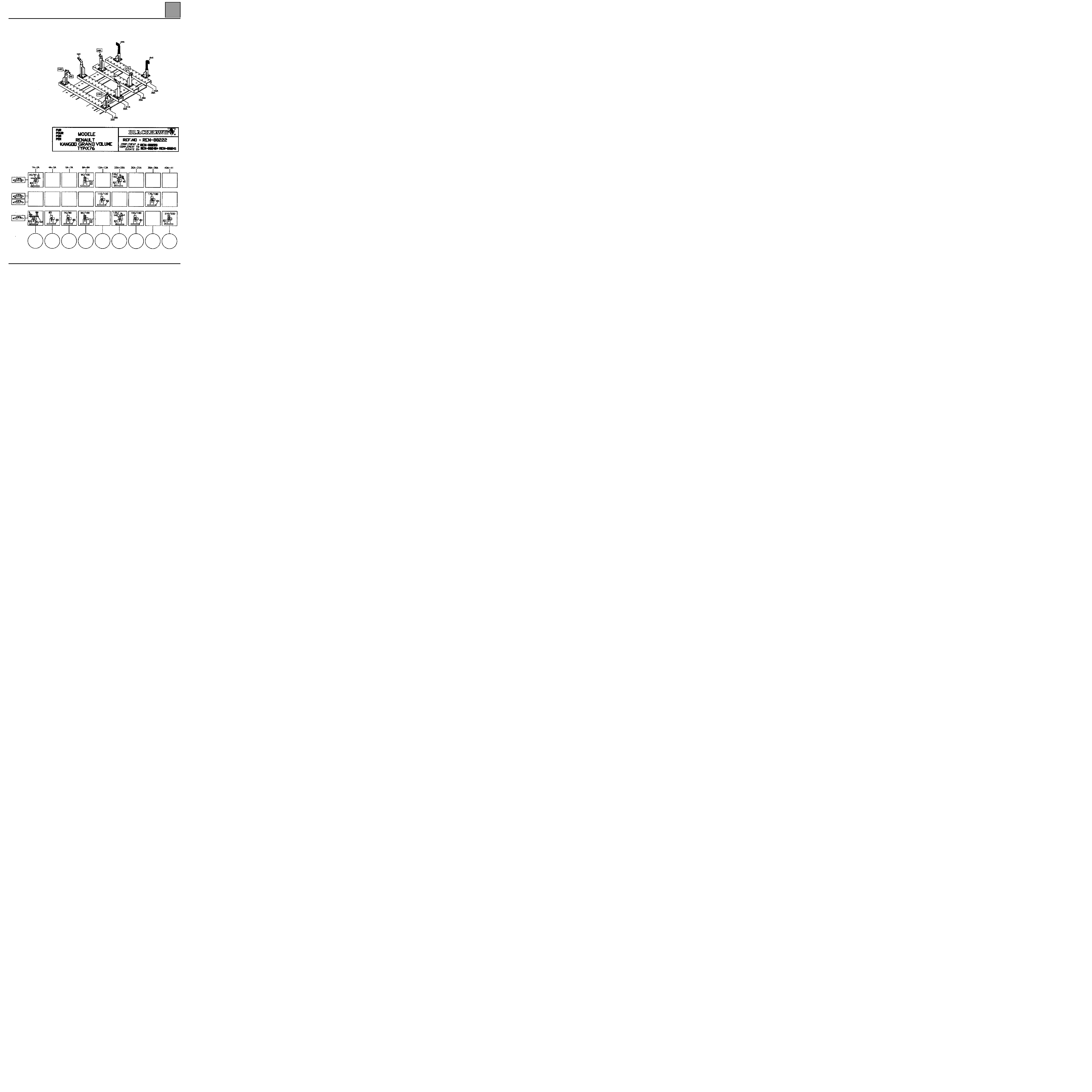
BLACKHAWK BODY JIG BENCH
PRF4013
GENERAL INFORMATION
Repair Bench
40
SPECIAL TOOLING PART NUMBER
BLACKHAWK
Special heads for MS System
Order at:
BLACKHAWK S.A.
Centre Eurofret
Rue de Rheinfeld
67100 STRASBOURG
Supplier’s part number: REN 88222
CELETTE
Specific plates for MZ System
Order at:
CELETTE S.A.
B.P. 9
38026 VIENNA
Supplier’s part number: 760 308
40-11

GENERAL INFORMATION
Tools and specific products
40
40-12
Tools and specific products
FITTING ADDED ELEMENTS
PRODUCTS
It is VITAL to fit the elements added to the KANGOO
Grand Volume with:
– the glue cartridge
part number 56 89 330 053 used by RENAULT
Industrial Vehicles,
– its grip primer part number 56 89 330 052,
– the vents with blades (sold singly)
part number 77 11 172 866,
– degreaser, heptane
part number 77 11 170 064,
SPECIAL NOTES
In the areas where the original paintwork has been
altered (to the sheet), it will be necessary to apply
anticorrosion impression type "ALPHA"
(part number 77 01 423 933).
The grip primer (part number 56 89 330 052) is applied
on the cataphoresis after sanding with a grey buffer on
the areas treated for "ALPHA" impression without
sanding after drying.
NOTE: for all additional instructions, refer to the
technical sheets for each product.
MATERIAL
PHOTO 14342 (SHOWN IN REPAIR MANUAL 338 SECTION 5)
GENERAL INFORMATION
Tools and specific products
40
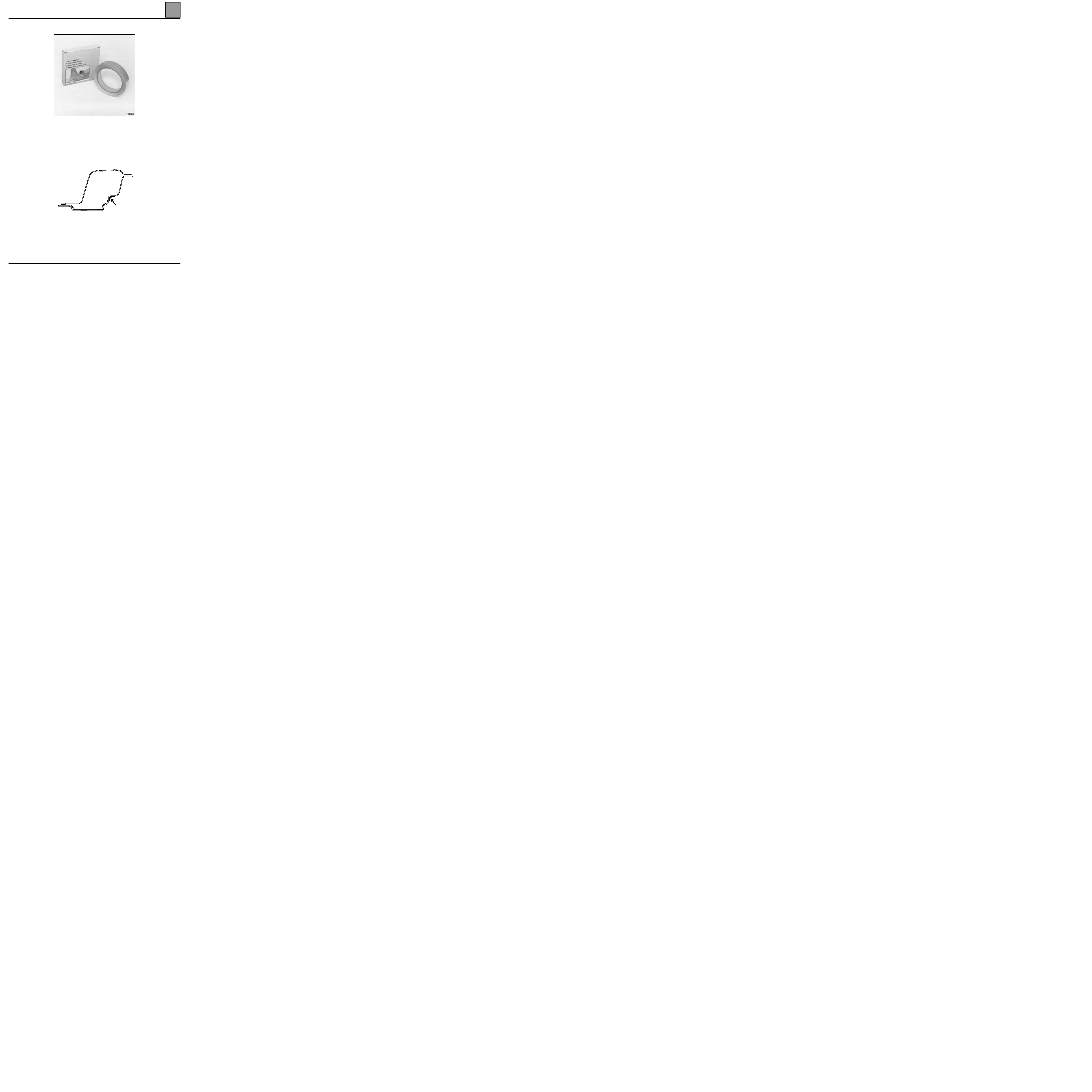
3M ADHESIVE FINISHING SEAL
(Part number 77 11 212 385)
It is applied before the paint, on a degreased primer.
Refer to section type (section 44-Aa, 44-Bb).
16595R4
40-13
LOWER STRUCTURE
Semi-rear end cross member
41
141
LOWER STRUCTURE
Semi-rear end cross member
INTRODUCTION
This part is changed in addition to changing the rear
end panel. It may be performed in two ways:
The separation operation should be carried out last,
when all the other links have been unhooked.
In the operation described below, only descriptions of
the joints specific to the part concerned are given.
Connections associated with the additional parts are
not taken into consideration. These connections will be
dealt with in their respective section (refer to contents).
COMPOSITION OF THE PART FROM THE PARTS
DEPARTMENT
Part assembled with:
– extreme rear cross member.
– lower central extender,
– striker support absorber,
– lower side extender,
– side cross member,
– side cross member stiffener,
– counter blade absorber.
PARTS CONCERNED (thickness in mm):
1 Side panel rain channel light support
1.5
2 Lights lower bracket
1
3 Side cross member stiffener
1
4 Extreme rear cross member
1.2
5 Side cross member
1
6 Side panel extender
1
7 Rear floor extender
0.8
8 Lower central extender
1
9 Basic body rearend panel
1
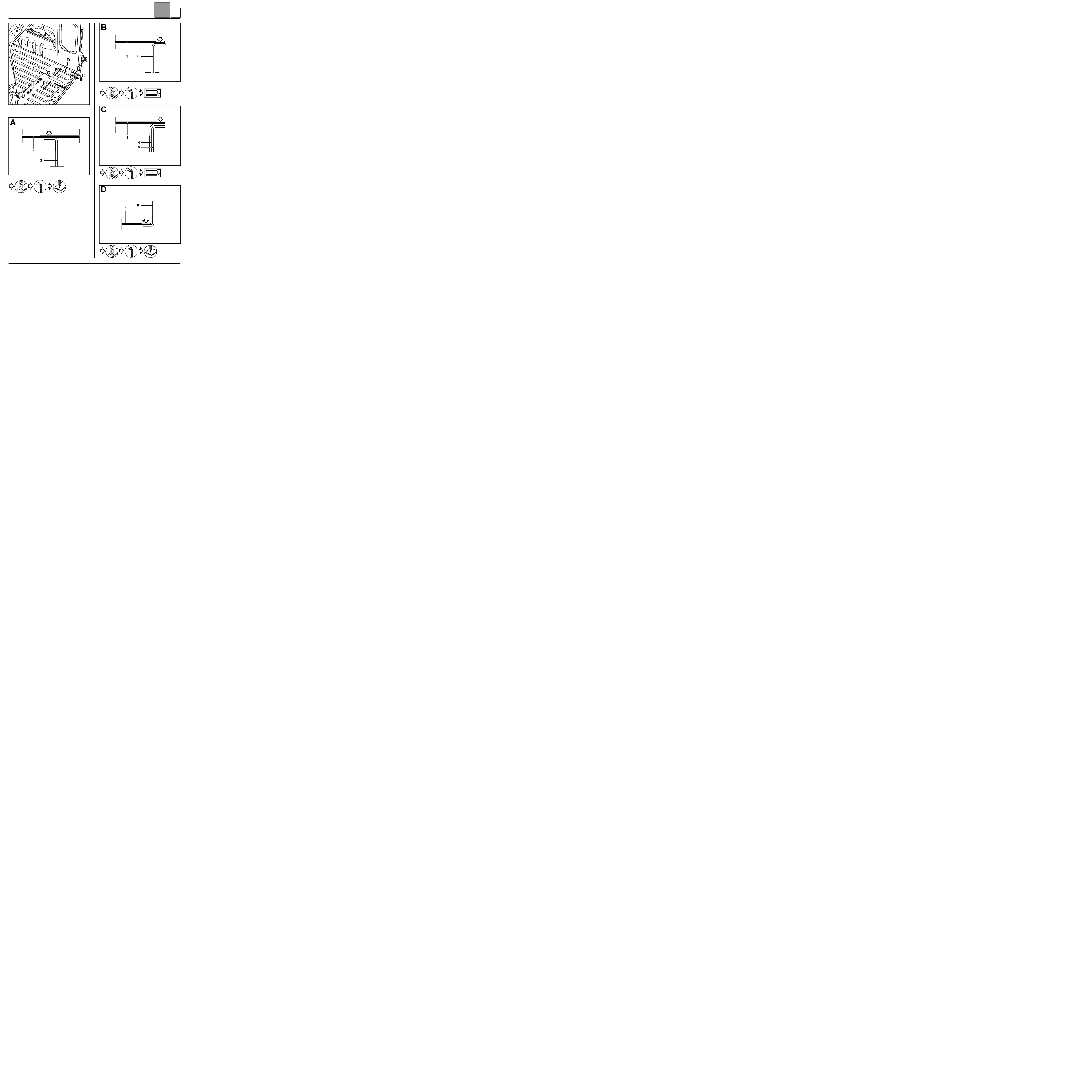
Cut 1
order a right or left demi-cross member,
Cut 2
order the two demi-cross members
then fit them in (A) or (B). For this
operation, the use of the body jig bench
is vital.
41-1
P
LOWER STRUCTURE
Semi-rear end cross member
41
41-2
SPECIAL FEATURE OF THE FOLLOWING
REPLACEMENT CUT 1
P
LOWER STRUCTURE
Semi-rear end cross member
41
41-3
P
LOWER STRUCTURE
Semi-rear end cross member
41
41-4
P
LOWER STRUCTURE
Semi-rear end cross member
41
41-5
J = two hexagonal screws Ø 8 mm
P
LOWER STRUCTURE
Semi-rear end cross member
41
41-6
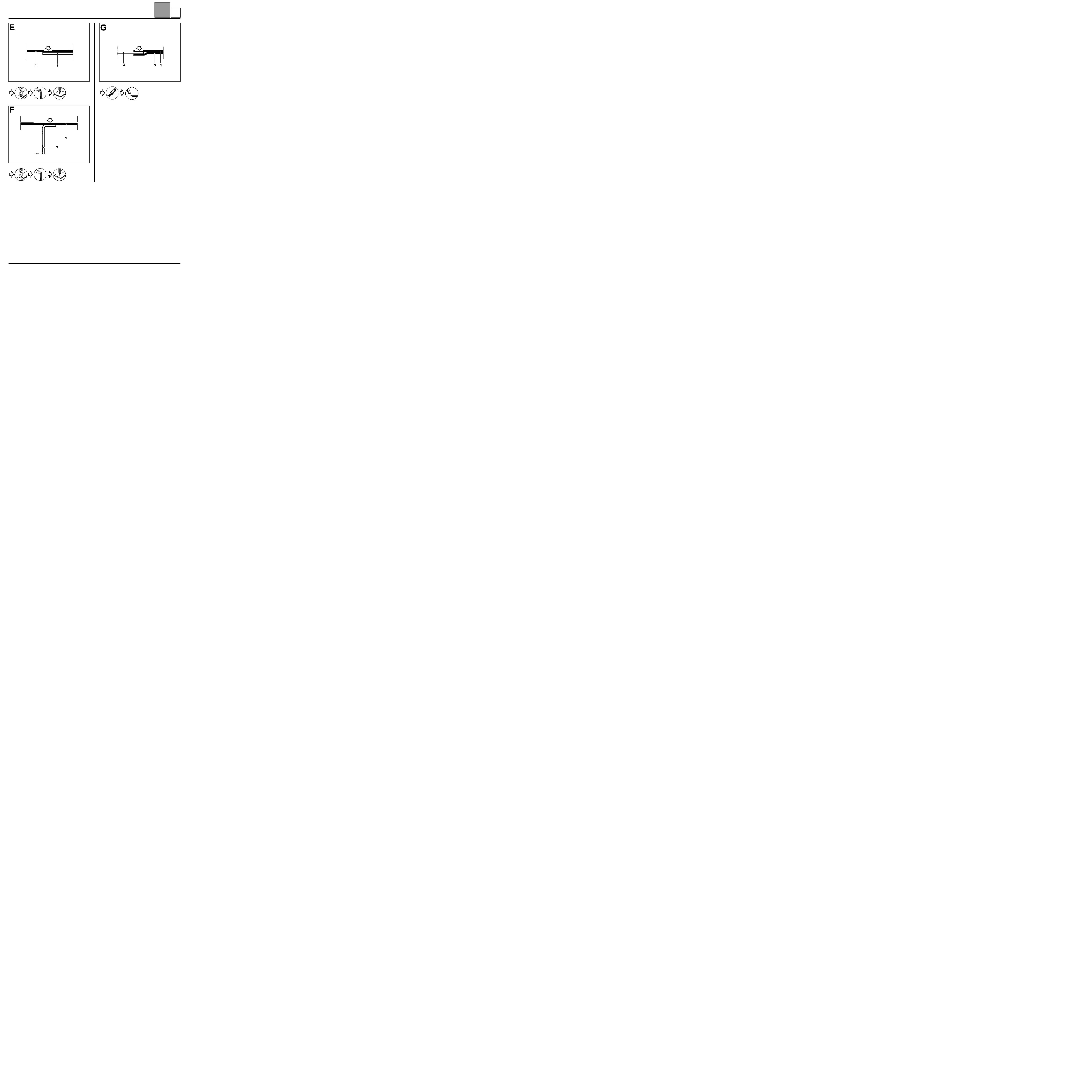
SPECIAL FEATURES OF THE FOLLOWING
REPLACEMENT CUT 2
L = two hexagonal screws Ø 8 mm
761P4-16604-1
P
LOWER STRUCTURE
Semi-rear end cross member
41
41-7
P
LOWER STRUCTURE
Rear floor extender
41
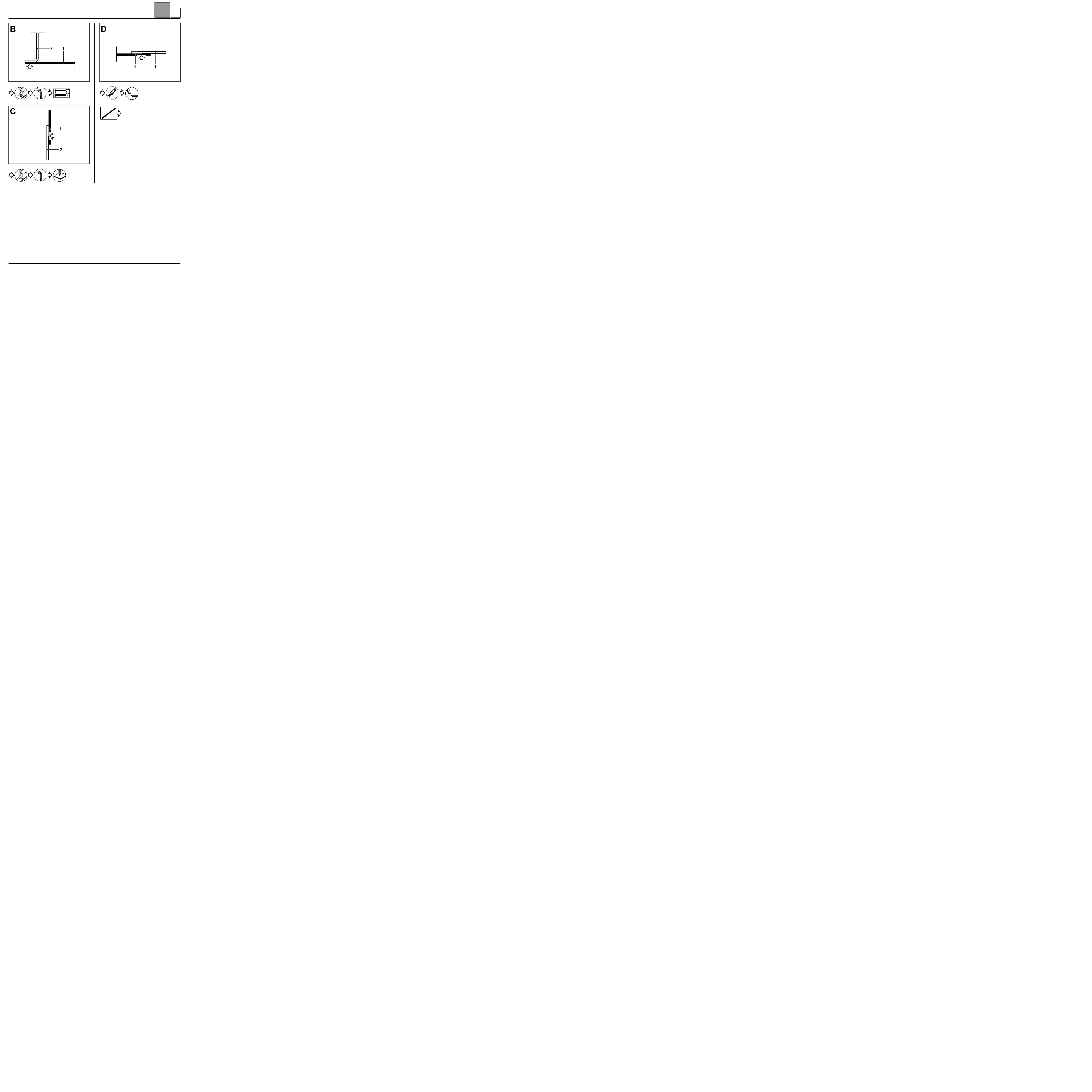
Rear floor extender
INTRODUCTION
For a rear impact, replacing this part is an additional
operation to replacing:
– the rearend panel,
– the demi-extreme rear cross member.
IMPORTANT: the separation operation should be
carried out last, when all the other links of the part
have been released, in order to move the part to
separate it.
In the operation described below, only descriptions of
the joints specific to the part concerned are given.
Connections associated with the additional parts are
not taken into consideration. These connections will be
dealt with in their respective sections (refer to
contents).
COMPOSITION OF THE PART FROM THE PARTS
DEPARTMENT
Part assembled with:
– seal contour,
– striker stiffener,
– towing ring plate.
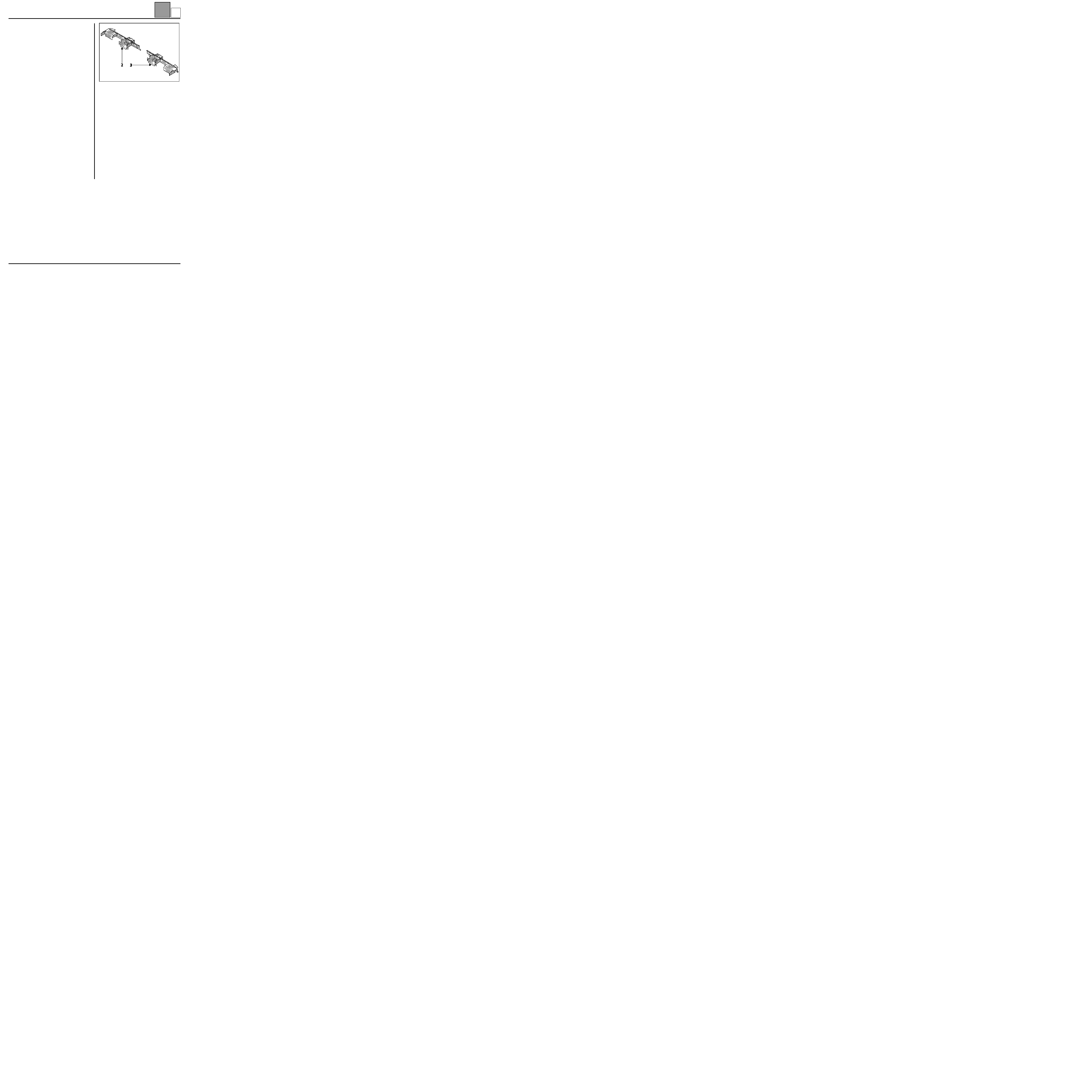
PARTS CONCERNED (thickness in mm):
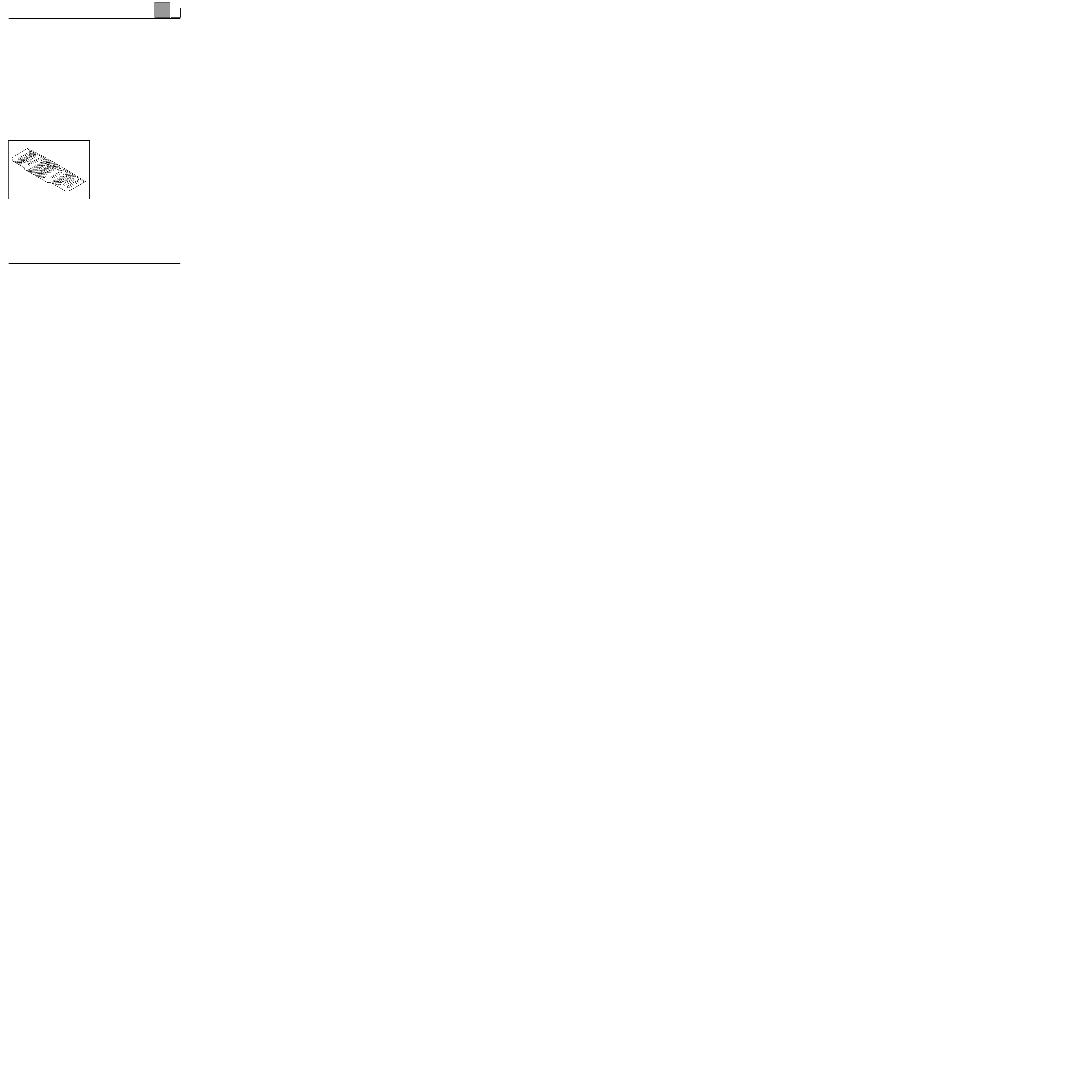
1 Rear floor extender
0.8
2 Rear section rear floor
1
3 Extreme rear cross member
1.2
4 Lights support lower bracket
1
5 Lights mounting side panel rain channel
1.5
6 Side inner panel extender
0.8
7 Central lower extender
1
8 Side cross member
1
9 Seal contour
1
41-8
X
LOWER STRUCTURE
Rear floor extender
41
41-9
H = two hexagonal screws Ø 8 mm
X
LOWER STRUCTURE
Rear floor extender
41
41-10
CAA11536-1R5A
CAA11538-1R5
TOE14621-5R7
X
UPPER REAR STRUCTURE
Basic body rear wing panel
44
144
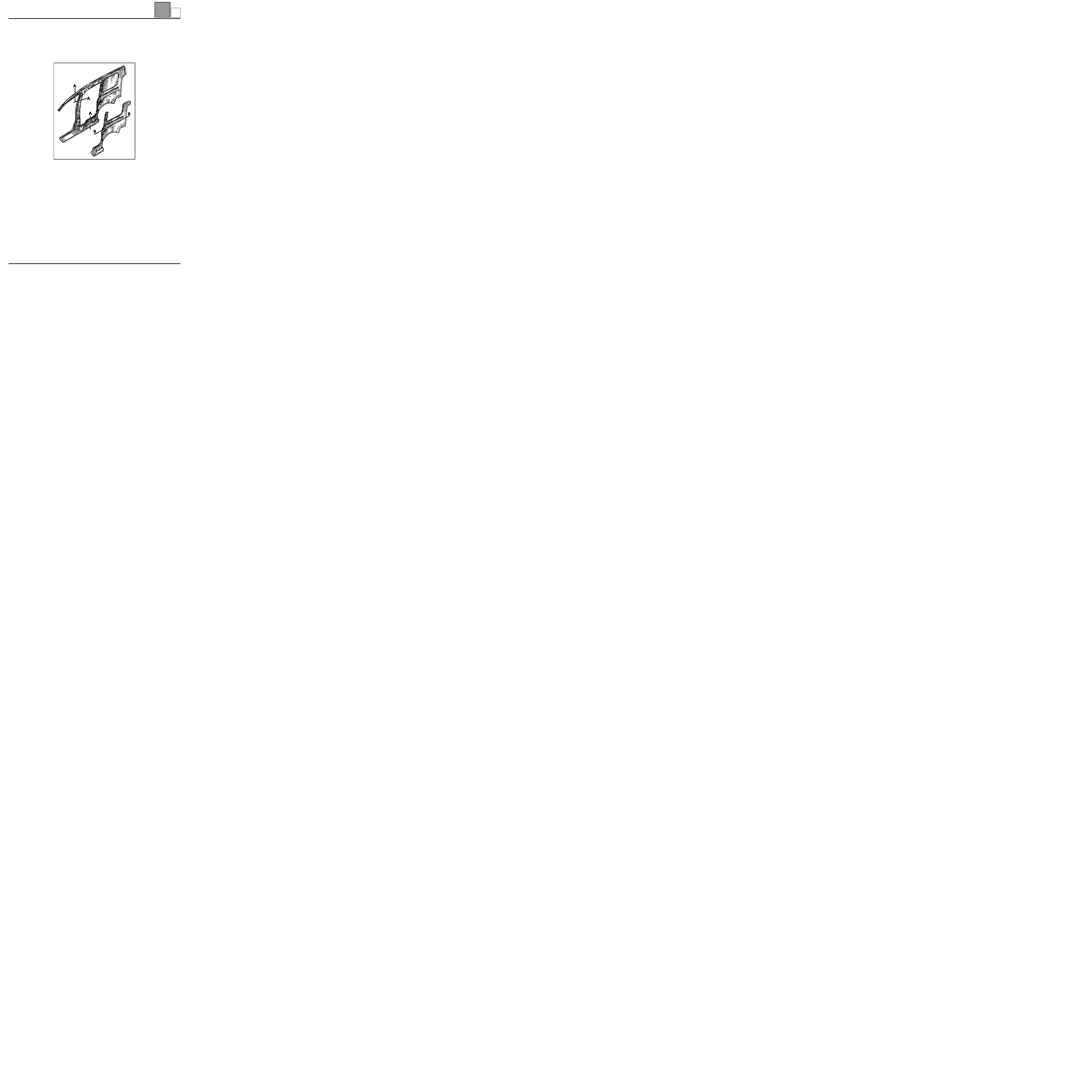
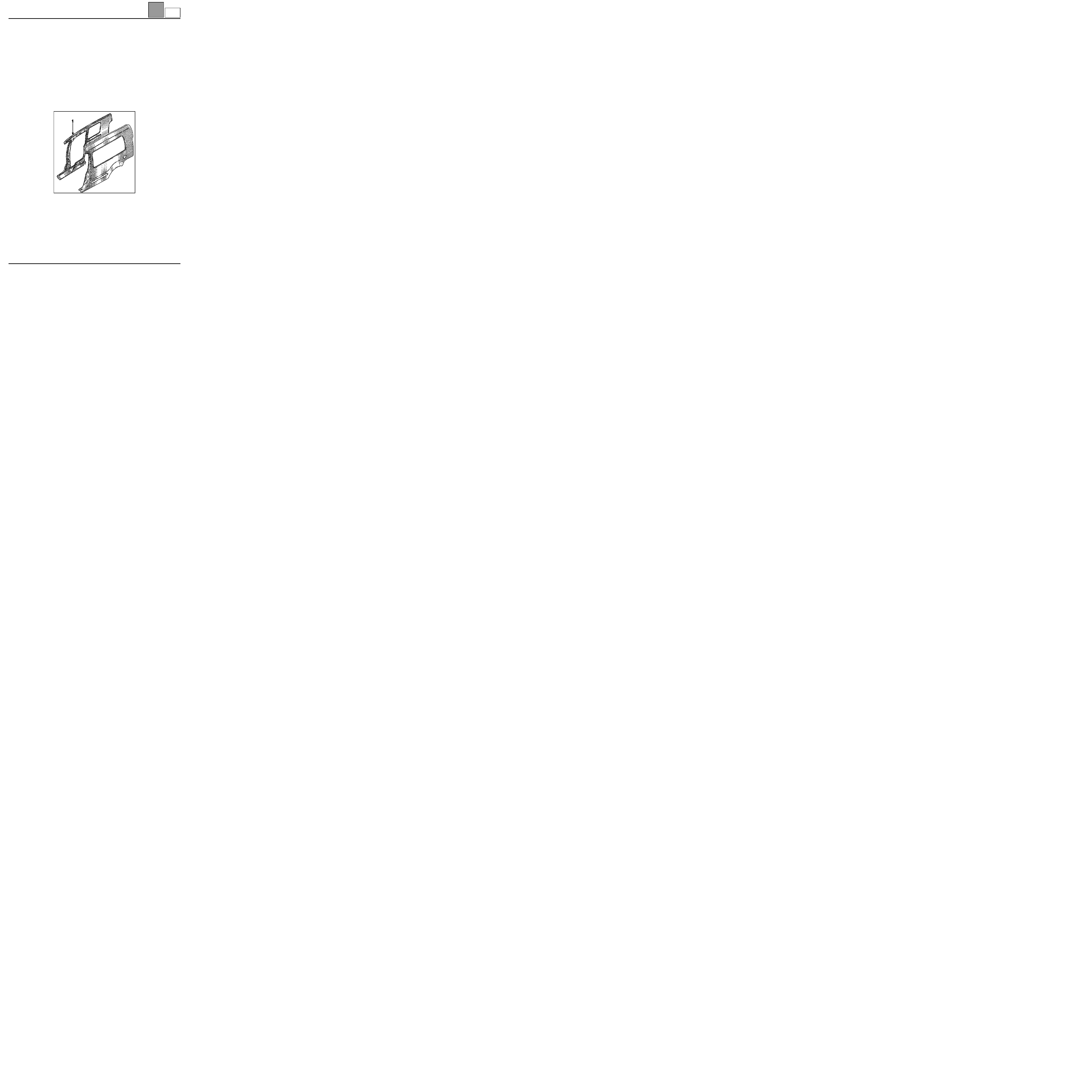
UPPER REAR STRUCTURE
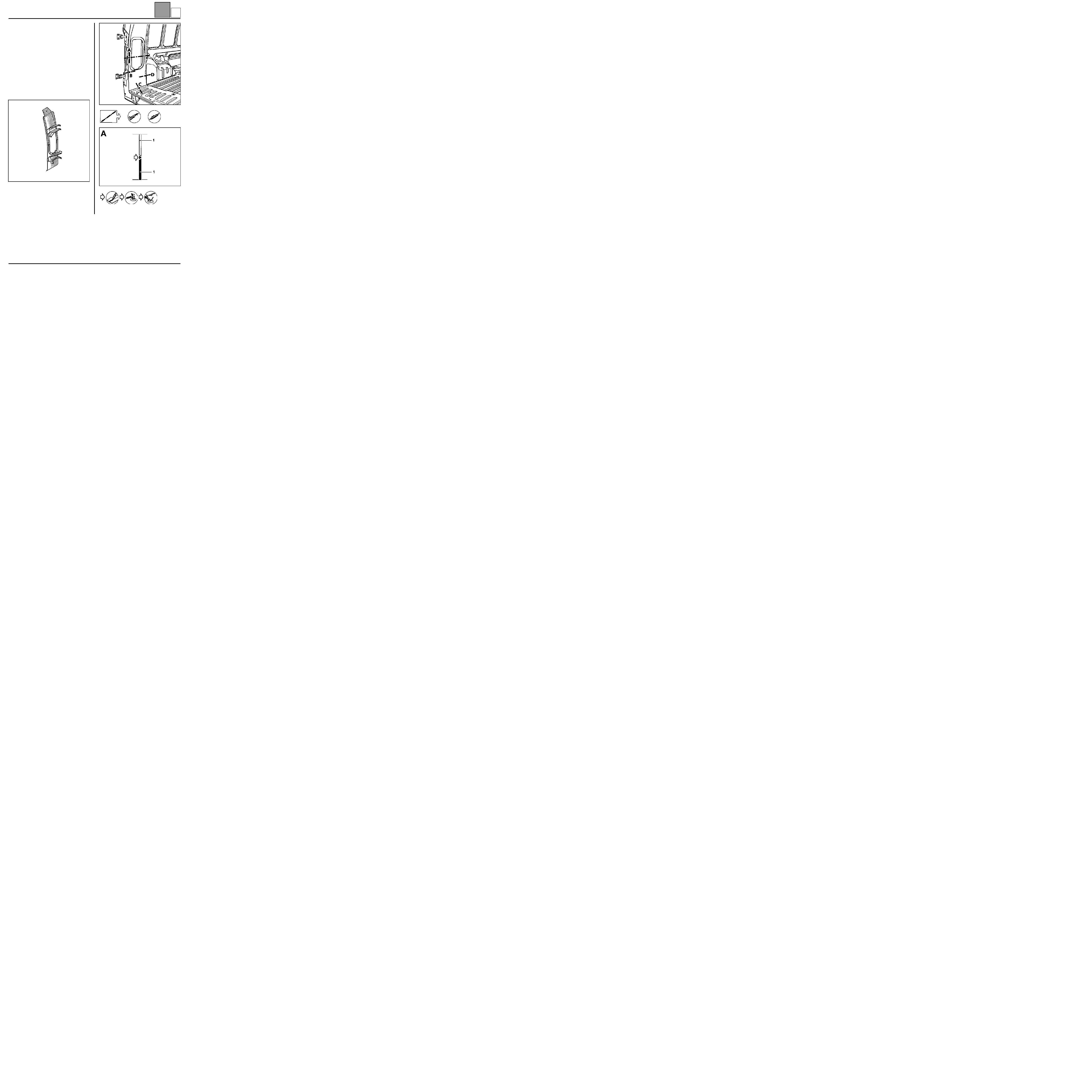
Basic body rear wing panel
INTRODUCTION
The basic body sheet wing panel of the Kangoo Grand
Volume may be replaced partially by following the
method given below.
COMPOSITION OF THE PART FROM THE PARTS
DEPARTMENT
PARTS CONCERNED (thickness in mm):
1 Basic body wing panel
0.8
44-1
A

UPPER REAR STRUCTURE
Basic body rear wing panel
44
44-2
or
SPECIAL FEATURE
Only operations related to the partial cut are dealt with
in this method. Other operations are described in
Repair Manual 326.
764A1-16607
CAS13033R7
CAS13033R7
A
UPPER REAR STRUCTURE
Rear wing panel fitted
44
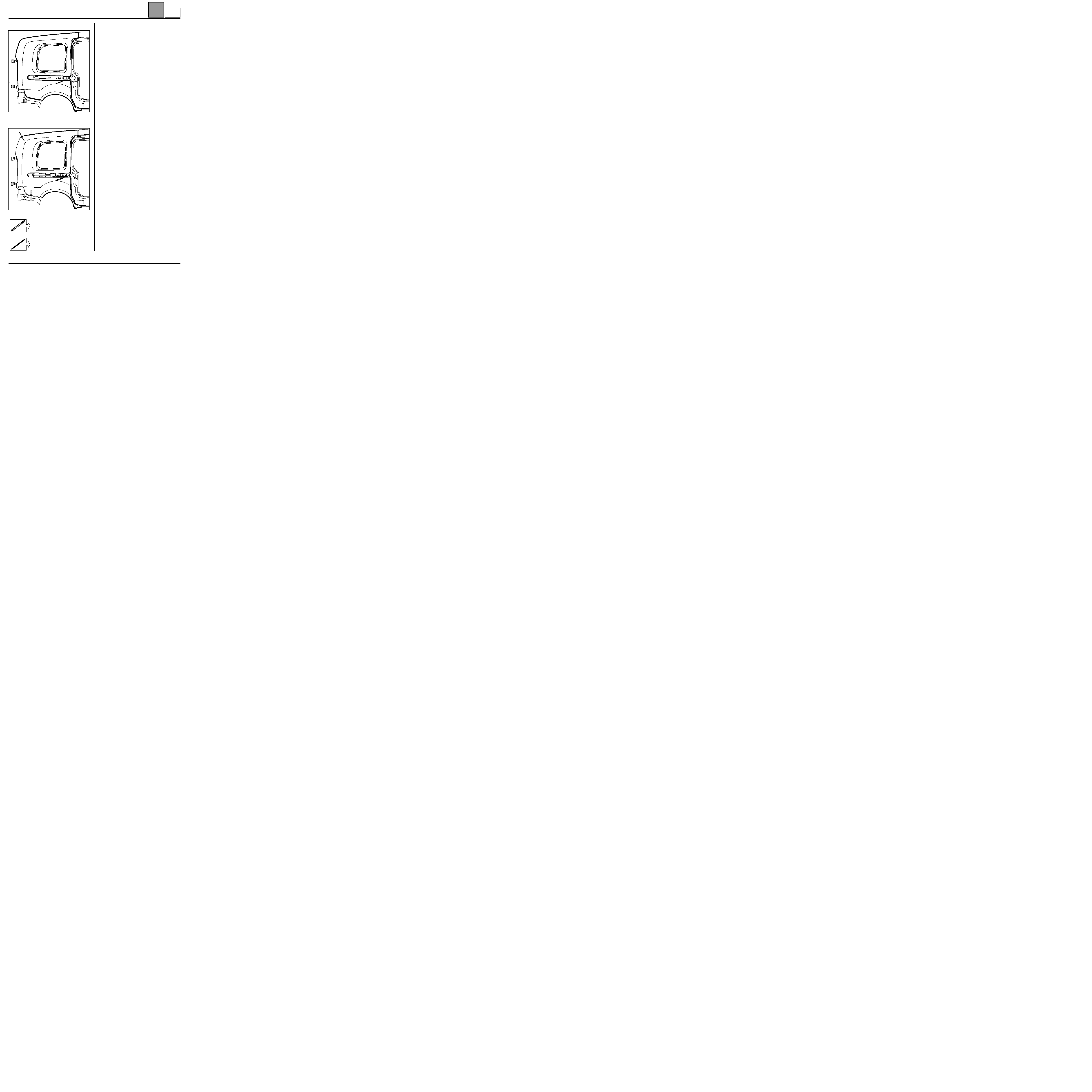
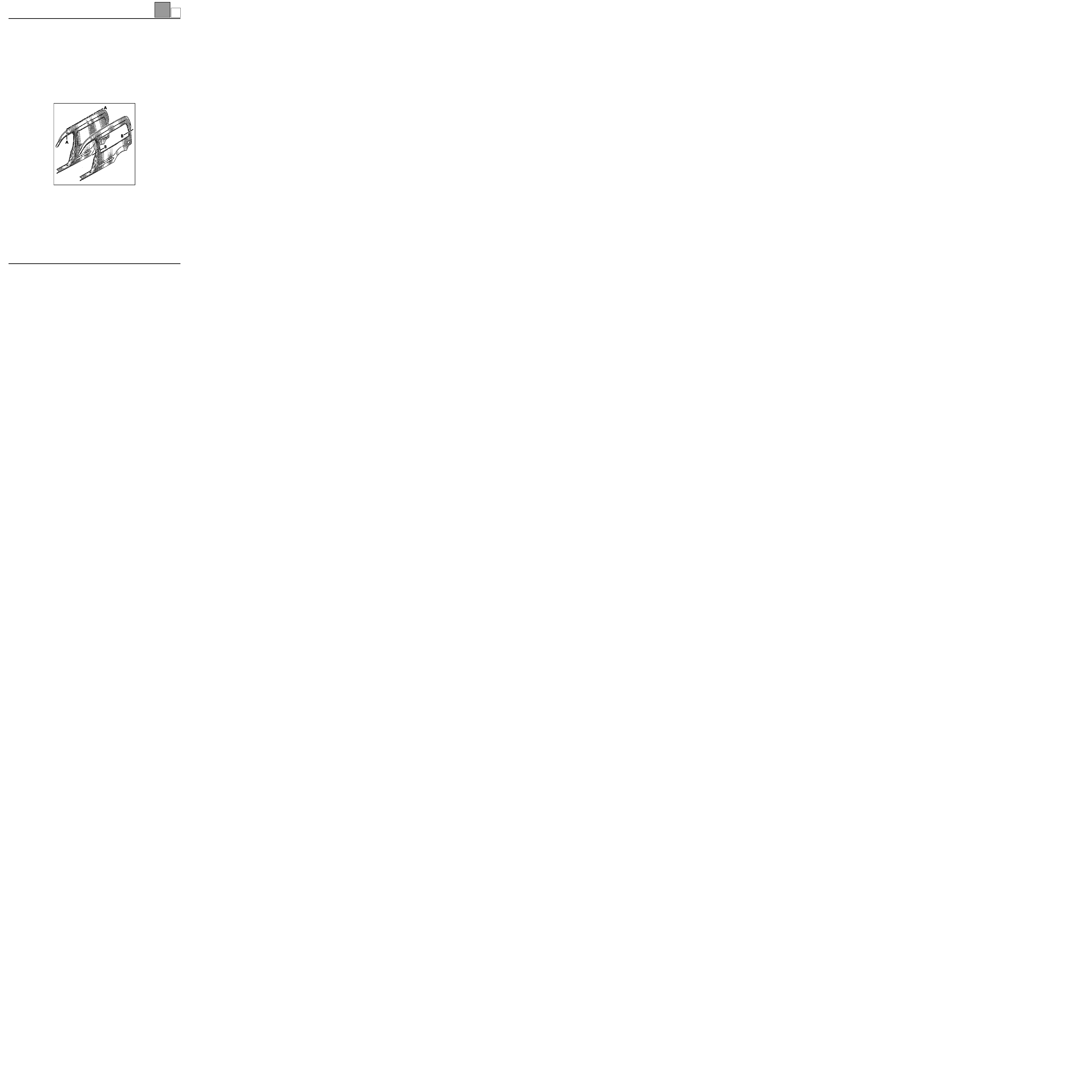
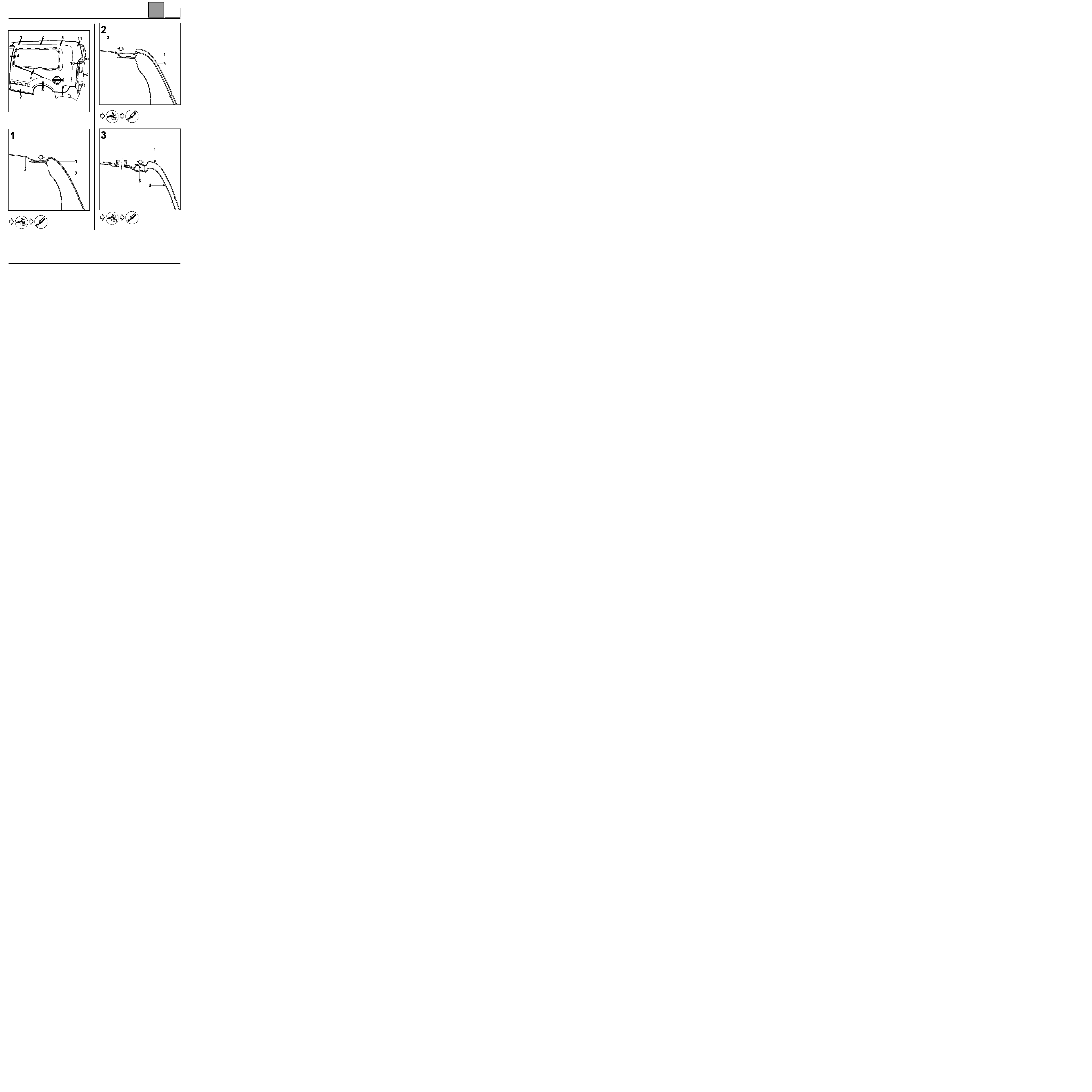
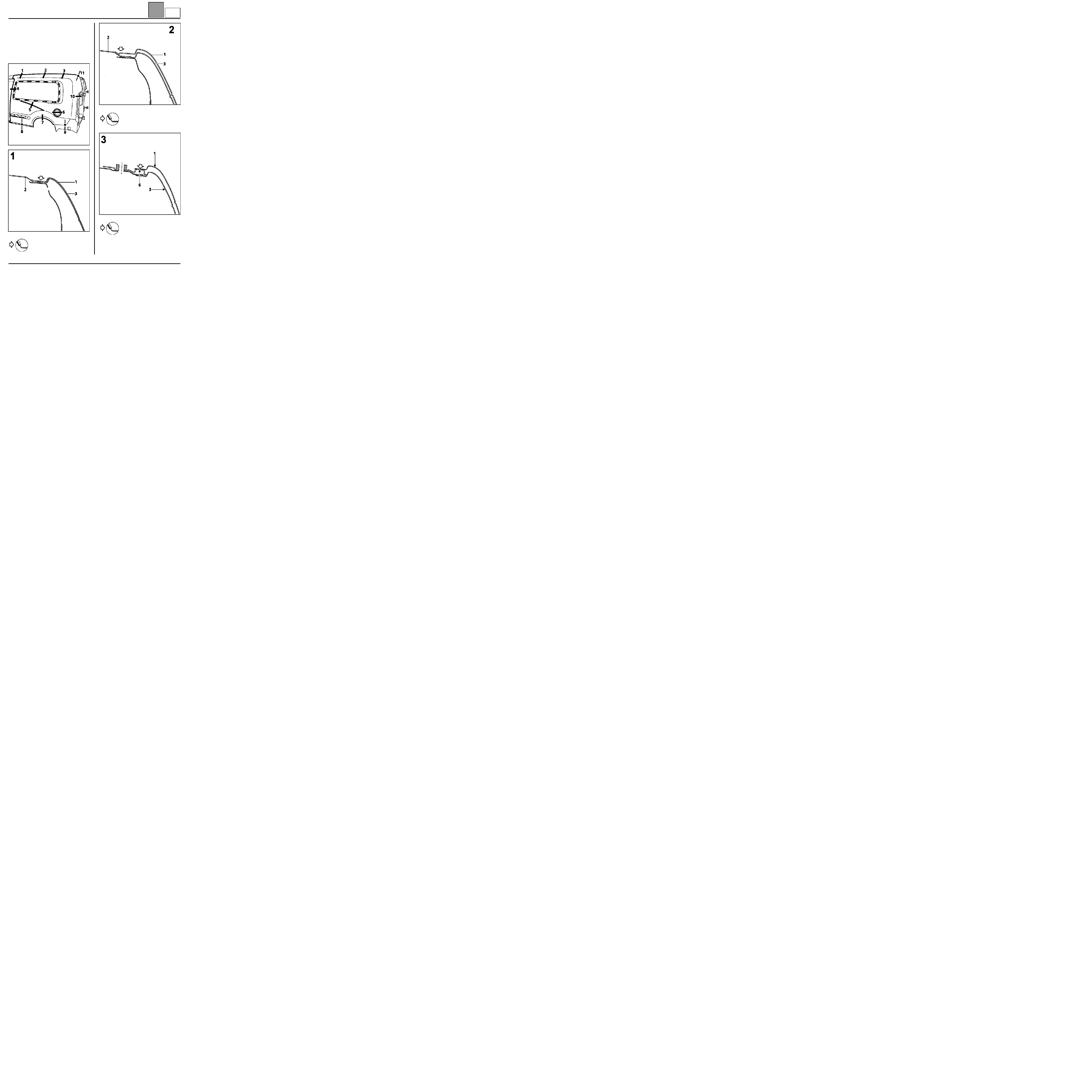
Rear wing panel fitted
INTRODUCTION
The replacement of this part is a basic operation for a
rear side impact.
It also requires the replacement of the Grand Volume
added roof, which is fitted on top at their common
contact (refer to section 45Aa).
In the operation described below, only descriptions of
the joints specific to the part concerned are given.
Information on additional parts will be dealt with in their
respective sections (refer to the contents).
COMPOSITION OF THE PART FROM THE PARTS
DEPARTMENT
Part 1.
IMPORTANT: in order to aid refitting, the panel
mounting on the body during repair is different from the
original mounting (refer to the method described
below).
PRF4417
44-3
Aa
UPPER REAR STRUCTURE
Rear wing panel fitted
44
44-4
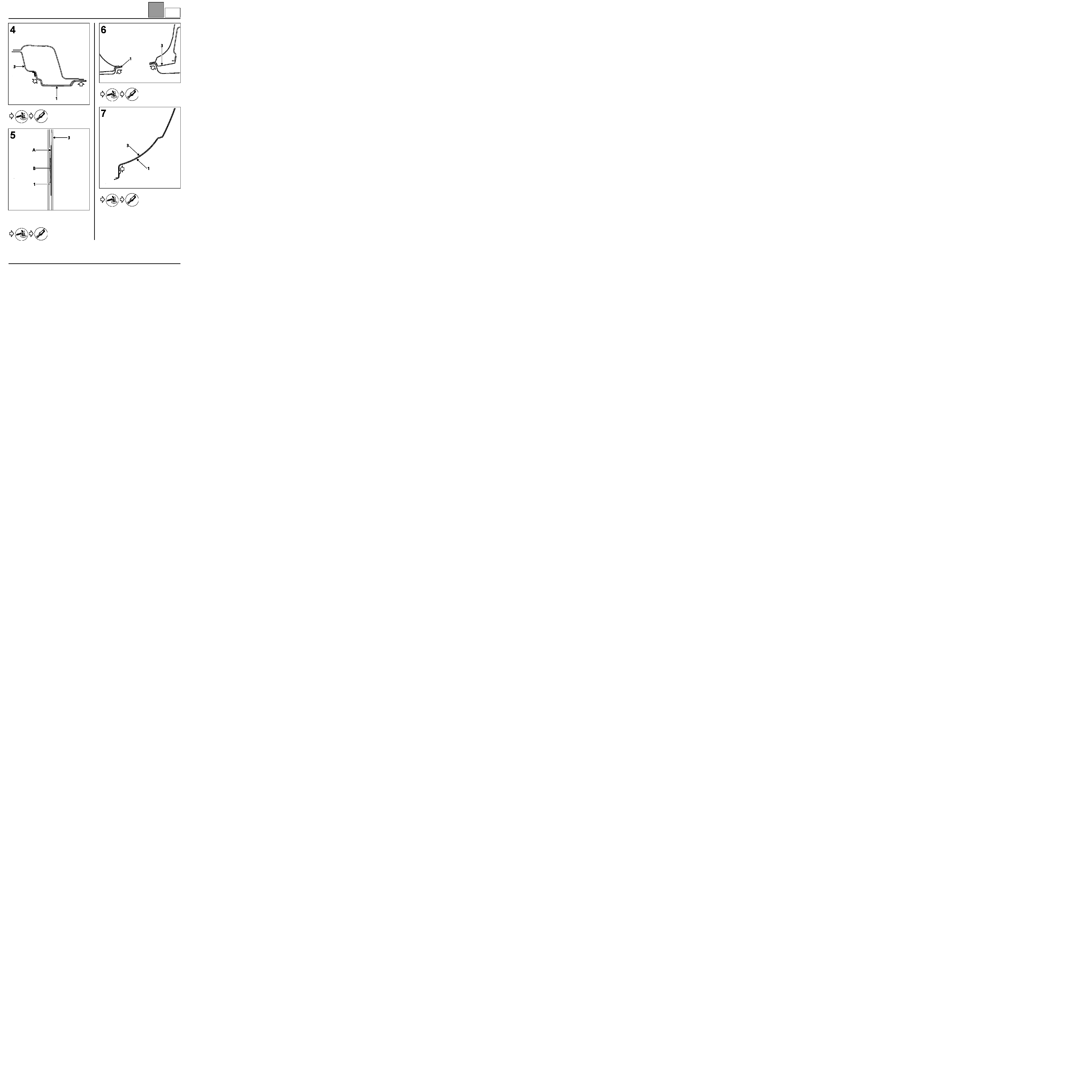
ORIGINAL MOUNTING
MOUNTING FOR REPAIR
Moulding ∅ 7 mm
Moulding ∅ 5 mm
PARTS CONCERNED (thickness in mm):
1 Added rear wing panel
0.8
2 Basic body roof
0.8
3 Basic body rear wing panel
0.8
4 Lights mounting side panel rain channel
1.5
5 Side panel extender
1
6 Upper rear corner stiffener
1
16619S
16619-1S
Aa

UPPER REAR STRUCTURE
Rear wing panel fitted
44
44-5
REMOVAL (ORIGINAL MOUNTING)
16619R1
16584-1R1
16586-1R1
16595R1
Aa

UPPER REAR STRUCTURE
Rear wing panel fitted
44
44-6
A
Masking tape width 5 cm
B
Adhesive moulding
16589R1
16596R1
16691R
16593R1
Aa
UPPER REAR STRUCTURE
Rear wing panel fitted
44
44-7
16592R1
16590R1
16588R1
16587R1
Aa

UPPER REAR STRUCTURE
Rear wing panel fitted
44
44-8
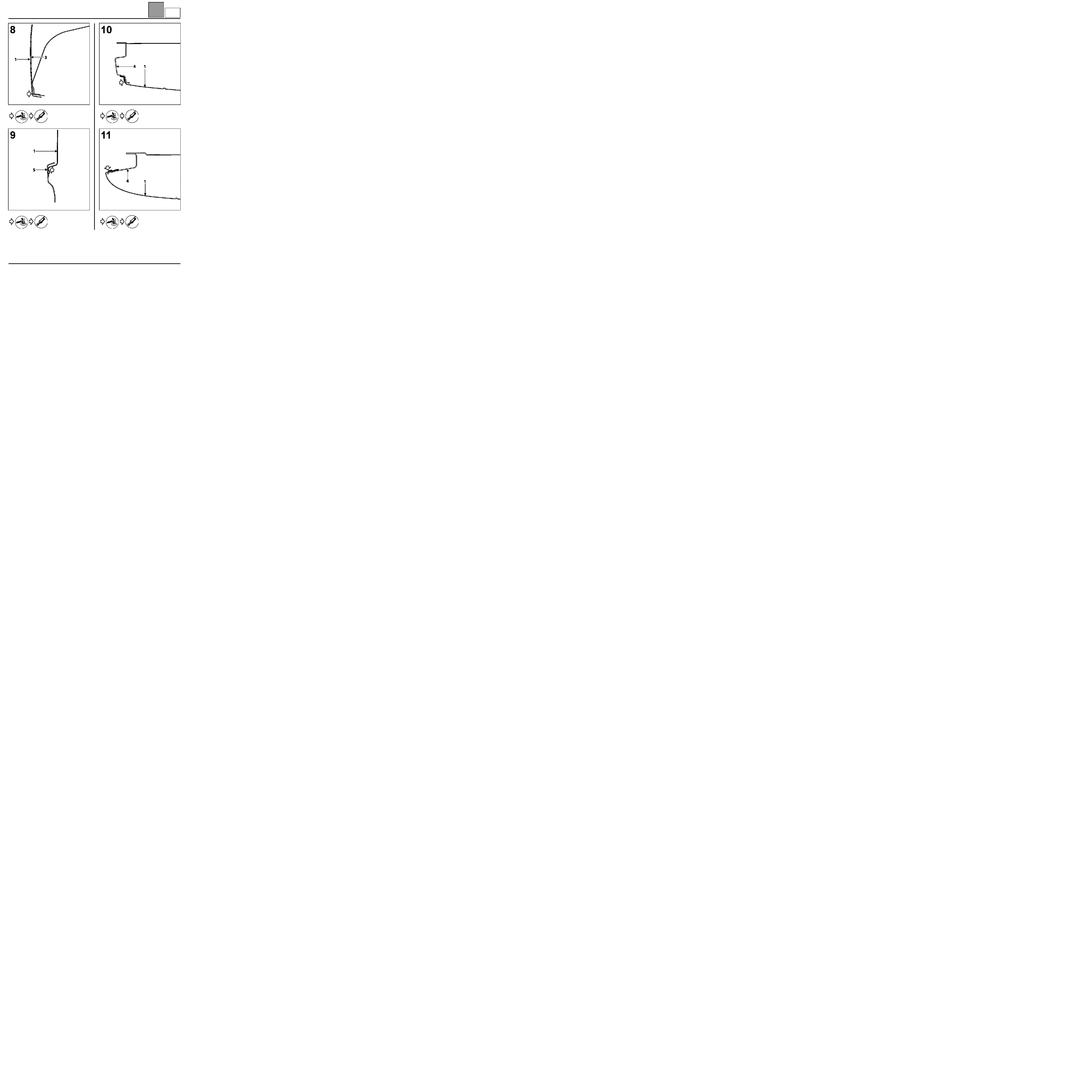
REFITTING
We recommend that you follow the order given below:
– position the panel on the body,
– bond the panel,
– fit and adjust it,
– strap the part (refer to section 44Bb),
– solder.
NOTE: the panel should be stuck and fitted to the body
as quickly as possible.
The adhesive moulding diameters change depending
on the glue course (see below).
16619-1R1
16584-1R1
Adhesive moulding ∅ 5 mm
between sheets (1) and (2)
16586-1R1
Adhesive moulding ∅ 5 mm
between sheets (1) and (6)
Aa

UPPER REAR STRUCTURE
Rear wing panel fitted
44
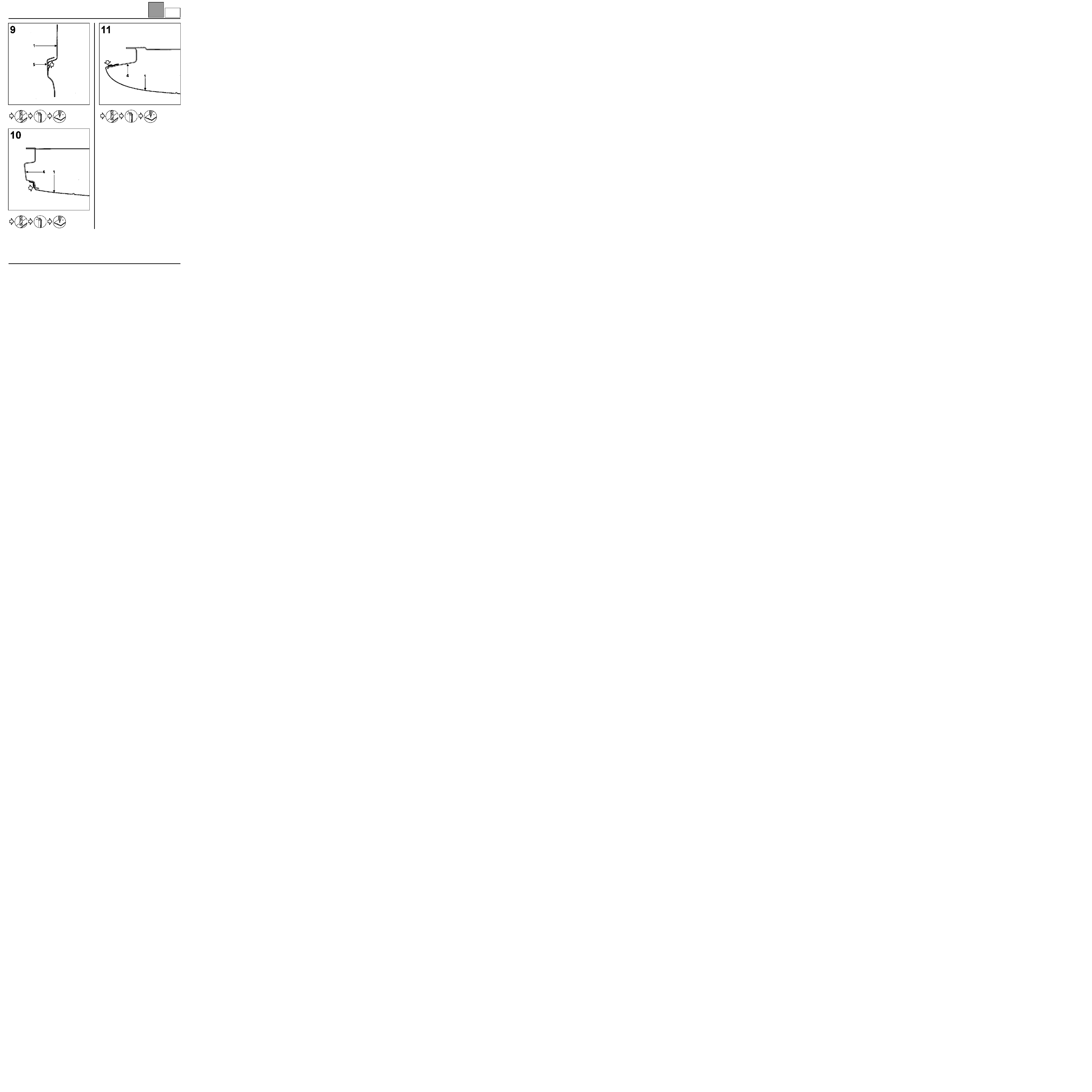
44-9
16595R1
A adhesive moulding ∅ 7 mm
between sheets (1) and (3)
B adhesive moulding ∅ 5 mm
between sheets (1) and (3)
16589R1
Adhesive moulding ∅ 7 mm
between sheets (1) and (3)
16596R1
Adhesive moulding ∅ 7 mm
between sheets (1) and (3)
Aa

UPPER REAR STRUCTURE
Rear wing panel fitted
44
44-10
SPECIAL FEATURE
Wide masking tape should be applied to the basic
body wing panel at the adhesive moulding position
(section 6), which will prevent the mounting body wing
panel being damaged when the part is removed once
more.
A
Masking tape width 5 cm
B
Adhesive moulding ∅ 7 mm
16691R
Between sheets (1) and (A)
16593R1
Adhesive moulding ∅ 5 mm
between sheets (1) and (3)
16592R1
Adhesive moulding ∅ 7 mm
between sheets (1) and (3)
Aa
UPPER REAR STRUCTURE
Rear wing panel fitted
44
44-11
Example of plating for stuck parts
(refer to section 44Bb Refitting).
16590R1
16588R1
16587R1
Aa
UPPER REAR STRUCTURE
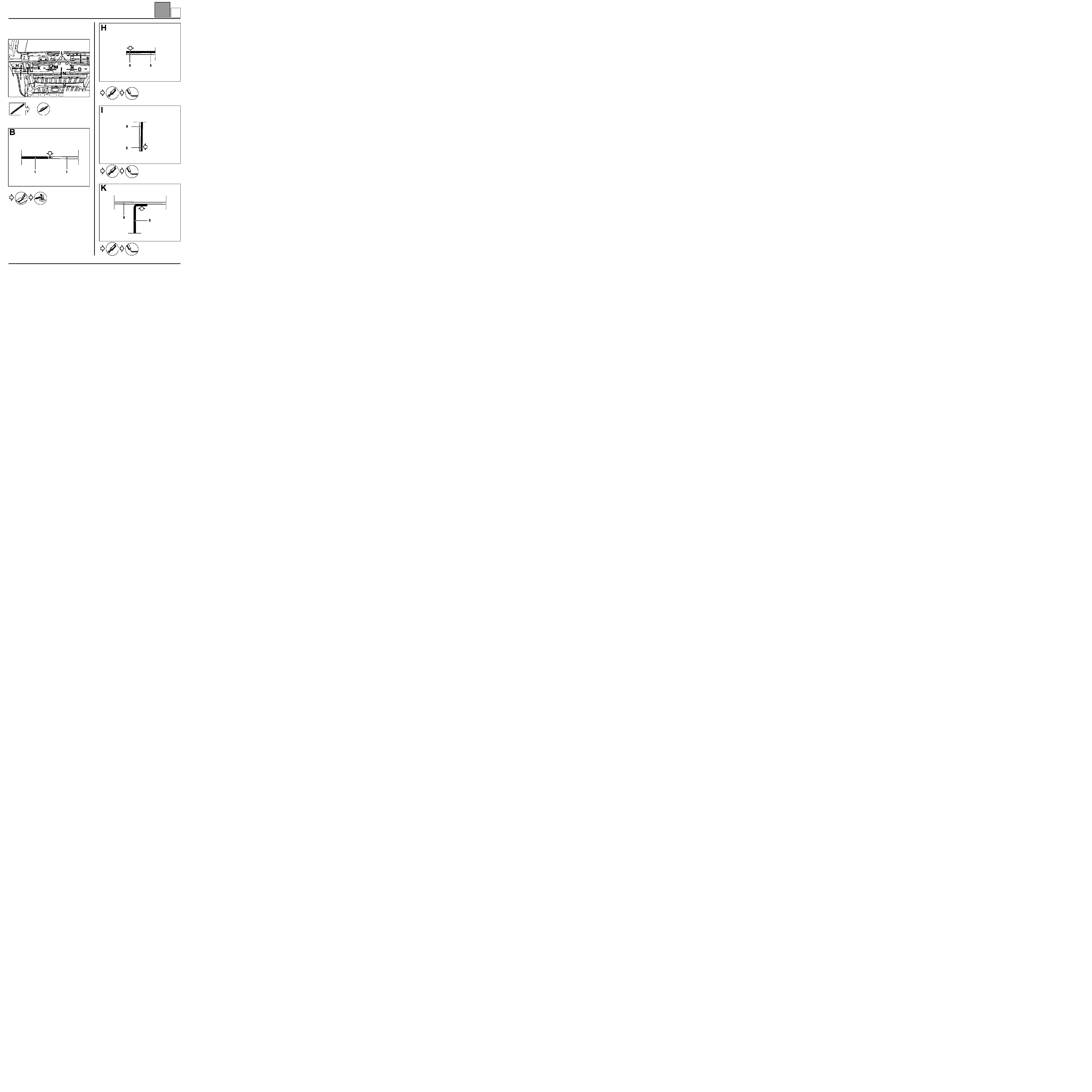
Basic body side panel
44
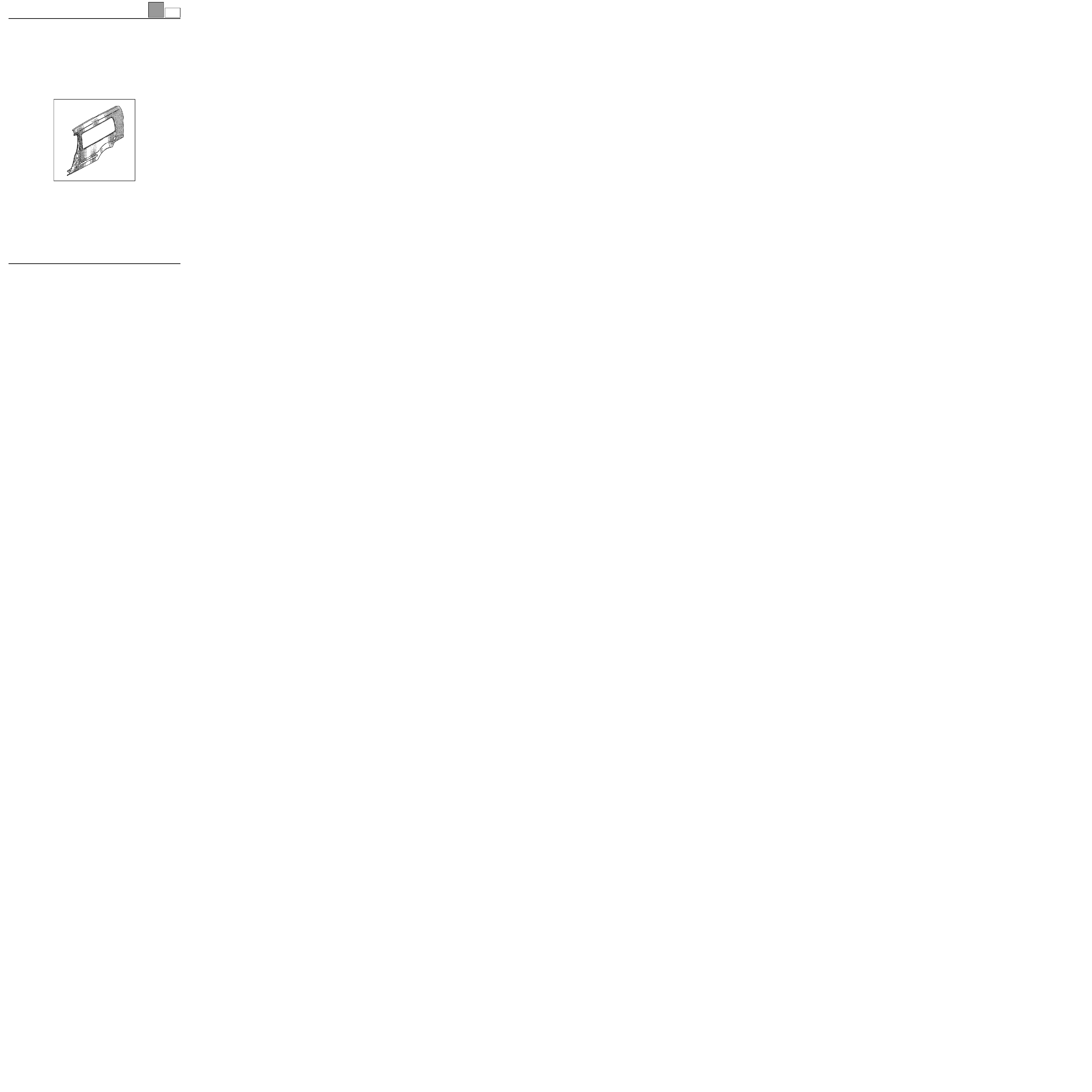
Basic body side panel
INTRODUCTION
The basic body side panel of the Kangoo Grand
Volume may be partially replaced by following the
method given below.
This is made possible by masking the connection
when the Grand Volume added panel is in place.
IMPORTANT: this method cannot be used on a series
Kangoo.
COMPOSITION OF THE PART FROM THE PARTS
DEPARTMENT
Part assembled with sliding door rail units and striker
plate mounting.
PARTS CONCERNED (thickness in mm):
1 Basic body side panel
0.8
44-12
B

UPPER REAR STRUCTURE
Basic body side panel
44
44-13
or
SPECIAL FEATURE
Only operations related to the partial cut are dealt with
in this method. Other operations are described in
Repair Manual 326.
764B1-16606
CAA11536-2R7
CAS13033R7
CAS13033R7
B
UPPER REAR STRUCTURE
Added side panel
44
Added side panel
INTRODUCTION
The replacement of this part is a basic operation for a
rear side impact.
It also requires the replacement of the Grand Volume
added roof, which is fitted on top at their point of
contact (refer to section 45AA).
In the operation described below, only descriptions of
the joints specific to the part concerned are given.
Information on parts will be dealt with in their
respective sections (refer to contents).
COMPOSITION OF THE PART FROM THE PARTS
DEPARTMENT
IMPORTANT: in order to aid refitting, the panel
mounting on the body during repair is different from the
original mounting (refer to the method described
below).
44-14
Bb

UPPER REAR STRUCTURE
Added side panel
44
44-15
ORIGINAL MOUNTING
MOUNTING FOR REPAIR
Moulding ∅ 7 mm
Moulding ∅ 5 mm
PARTS CONCERNED (thickness in mm):
1 Added side panel
0.8
2 Basic body roof
0.8
3 Basic body side panel
0.8
4 Lights mounting side panel rain channel
1,5
5 Side panel extender
1
6 Upper rear corner stiffener
1
Bb
UPPER REAR STRUCTURE
Added side panel
44
44-16
REMOVAL (ORIGINAL MOUNTING)
Bb
UPPER REAR STRUCTURE
Added side panel
44
44-17
A
Masking tape width 5 cm
B
Adhesive moulding
Bb

UPPER REAR STRUCTURE
Added side panel
44
44-18
16587R3
Bb
UPPER REAR STRUCTURE
Added side panel
44
44-19
REFITTING
We recommend that you follow the order given below:
– bond the panel,
– adjust and strap the part (refer to section 44Bb),
– solder.
ATTENTION: The adhesive moulding diameters
change depending on the glue course (see below).
16620-1R
16584-1R3
Adhesive moulding ∅ 5 mm
between sheets (1) and (2)
A
Adhesive moulding ∅ 5 mm
between sheets (1) and (3)
B
Adhesive moulding ∅ 7 mm
between sheets (1) and (3)
Adhesive moulding ∅ 5 mm
between sheets (1) and (6)
Bb

UPPER REAR STRUCTURE
Added side panel
44
44-20
SPECIAL FEATURE
Wide masking tape should be applied to the basic
body wing panel at the adhesive moulding position
(section 6), which will prevent the mounting body side
panel being damaged when the part is removed once
more.
A
Masking tape width 5 cm
B
Adhesive moulding ∅ 7 mm
16595R3
A
Adhesive moulding ∅ 5 mm
between sheets (1) and (3)
B
Adhesive moulding ∅ 7 mm
between sheets (1) and (3)
16691R
Between sheets (1) and (A)
Bb
UPPER REAR STRUCTURE
Added side panel
44
44-21
16591R1
Adhesive moulding ∅ 7 mm
between sheets (1) and (3)
16592R3
Adhesive moulding ∅ 5 mm
between sheets (1) and (3)
16593R3
16590R3
Bb
UPPER REAR STRUCTURE
Added side panel
44
44-22
1
Example of plating for the stuck parts
2
Fit the weather-strip for the front door in the
opposite direction on the door. Close the door,
then position the straps (see below).
ATTENTION: protect the seals from glue spillages
using masking tape.
16588R3
16587R3
16631S
Bb

UPPER REAR STRUCTURE
Added side panel
44
44-23
3
Use bolts and nuts of ∅ 6 mm and wide washers
for plating the panel at the side strip clampingholes.
16632S
Bb
UPPER REAR STRUCTURE
Side panel extender
44
Side panel extender
INTRODUCTION
This part may be replaced in two ways:
1
total replacement complementary to the side panel,
2
partial changing complementary to the skirt and
lights mounting side panel rain channel.
In the operation described below, only descriptions of
the joints specific to the part concerned are given.
Information on parts to which this is additional, will be
dealt with in their respective sections (refer to
contents).
COMPOSITION OF THE PART FROM THE PARTS
DEPARTMENT
Part on its own.
PARTS CONCERNED (thickness in mm):
1
Side panel extender
1
2
Side cross member
1
3
Lower lights bracket
1
4
Extreme rear cross member
1,2
5
Basic body side panel extender
1
44-24
G

UPPER REAR STRUCTURE
Side panel extender
44
44-25
1 - COMPLETE REPLACEMENT
764G1-16608
TOA14581R7
TOA14581R7
TOH14634R7
TOB14593R6
G
UPPER REAR STRUCTURE
Side panel extender
44
44-26
Moulding ∅ 5 mm
G

UPPER REAR STRUCTURE
Side panel extender
44
44-27
2 - PARTIAL CHANGING SPECIAL FEATURES
764G2-16646
CAA11536-2R7
G
UPPER REAR STRUCTURE
Side inner panel extender
44
Side inner panel extender
INTRODUCTION
Replacing this part is an additional operation to the
rain channel lights support after a rear impact.
This operation may be carried out partially.
In the operation described below, only descriptions of
the joints specific to the part concerned are given.
Information on parts will be dealt with in their
respective sections (refer to contents).
COMPOSITION OF THE PART FROM THE PARTS
DEPARTMENT
Assembled part with hinge stiffener.
PARTS CONCERNED (thickness in mm):
1 Side inner panel extender
0.8
2 Lights support side panel rain channel
1.5
3 Rear floor extender
0.8
4 Basic body side panel lining
0.7
or
PRF4413
16629R
CAS13033R7
44-28
I
UPPER REAR STRUCTURE
Side inner panel extender
44
44-29
Moulding ∅ 5 mm
CAB11539-1R1
CAA11536-2R3
CAA11536-2R6
I
UPPER REAR STRUCTURE
Upper rear corner stiffener
44
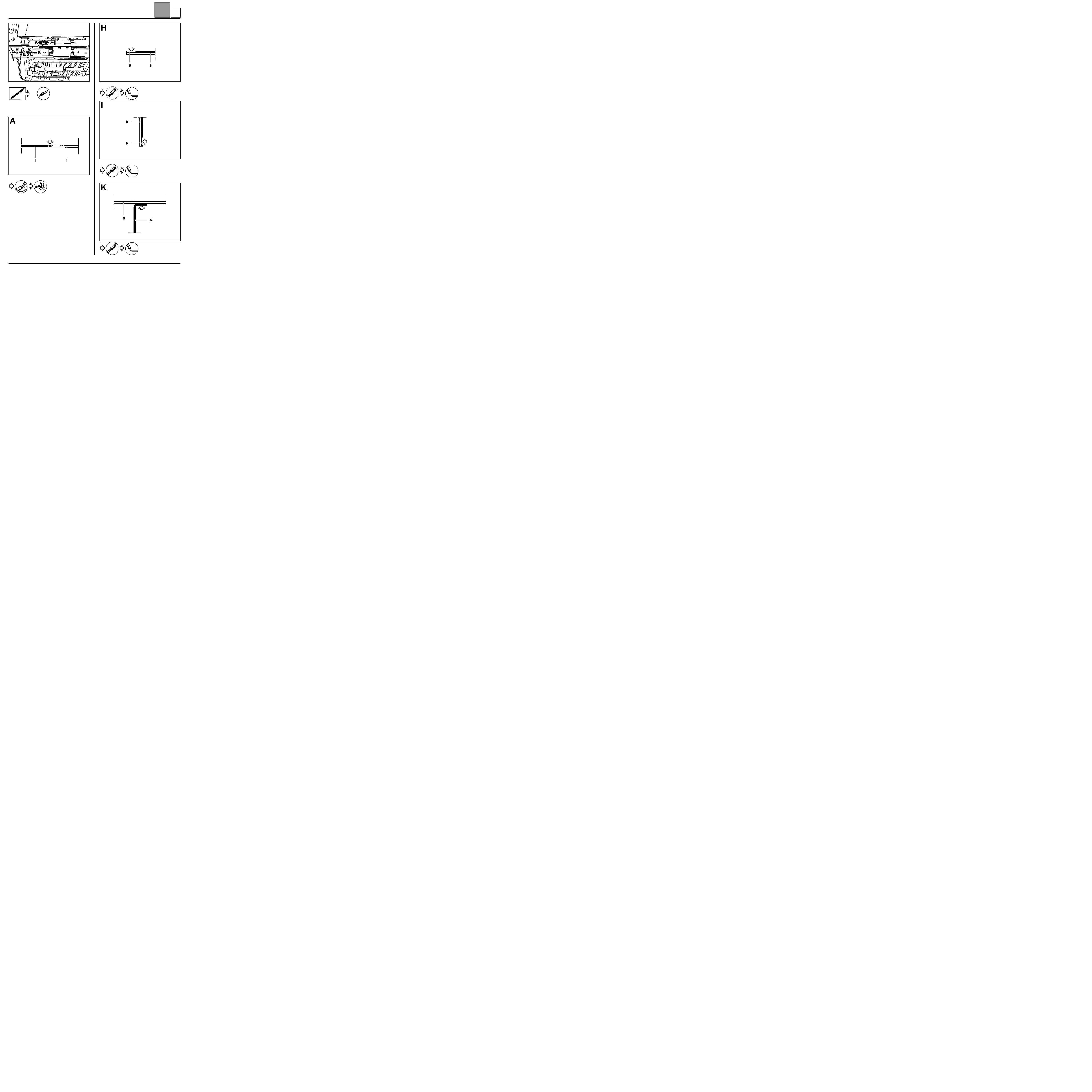
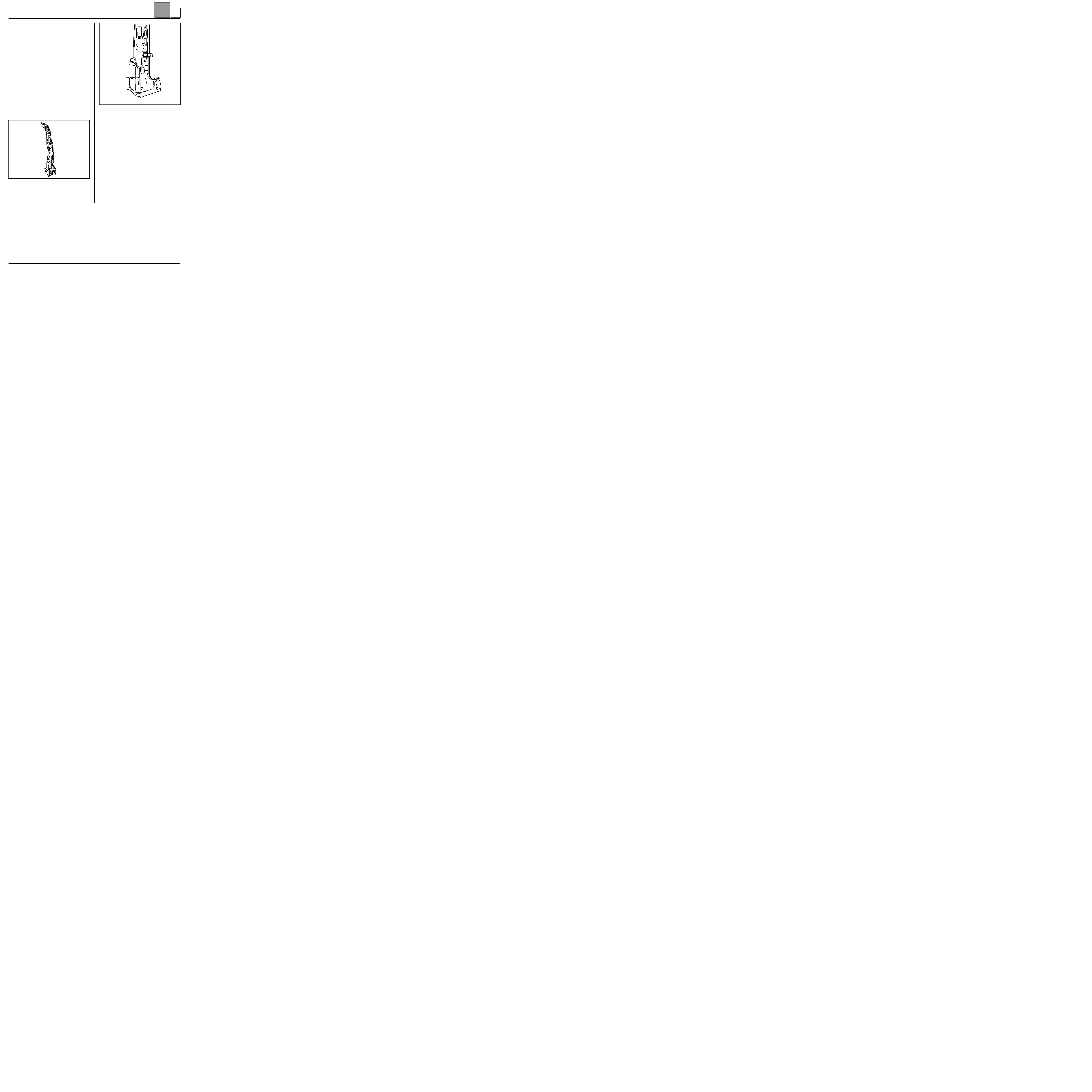
Upper rear corner stiffener
INTRODUCTION
This part is changed in addition to changing roof with
cross member and inner panel.
In the operation described below, only descriptions of
the joints specific to the part concerned are given.
Information on parts will be dealt with in their
respective sections (refer to contents).
COMPOSITION OF THE PART FROM THE PARTS
DEPARTMENT
Part on its own.
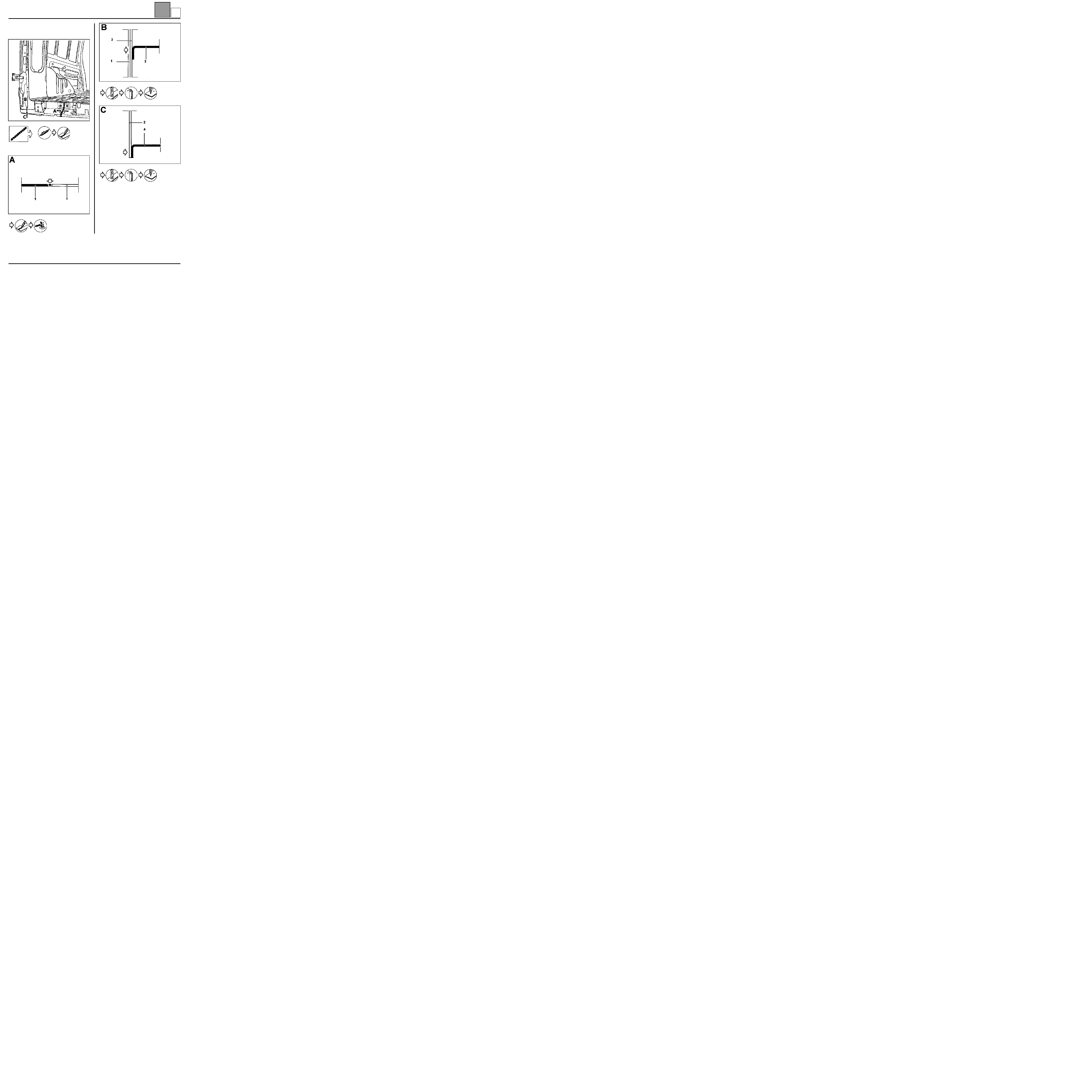
PARTS CONCERNED (thickness in mm):
1 Upper rear corner stiffener
1
2 Side inner panel extender
0.8
3 Roof rear cross member
0.8
4 Lights support side panel rain channel
1.5
5 Roof inner panel extender
0.8
6 Basic body roof rear cross member
0.8
7 Basic body roof
0.8
8 Inner panel stiffener
0.8
764J1-16628
CAA11536-2R4
44-30
J

UPPER REAR STRUCTURE
Upper rear corner stiffener
44
44-31
Moulding ∅ 5 mm
Moulding ∅ 5 mm
CAA11536-2R5
CAW13605-4R1
CAA11536-2R2
CAA11536-2R2
J
UPPER REAR STRUCTURE
Upper rear corner stiffener
44
44-32
I = two hexagonal screws ∅ 8 mm.
764J2-16643-1
CAA11536-2R5
CAA11538-1R4A
J
UPPER REAR STRUCTURE
Lights mounting side panel rain channel
44
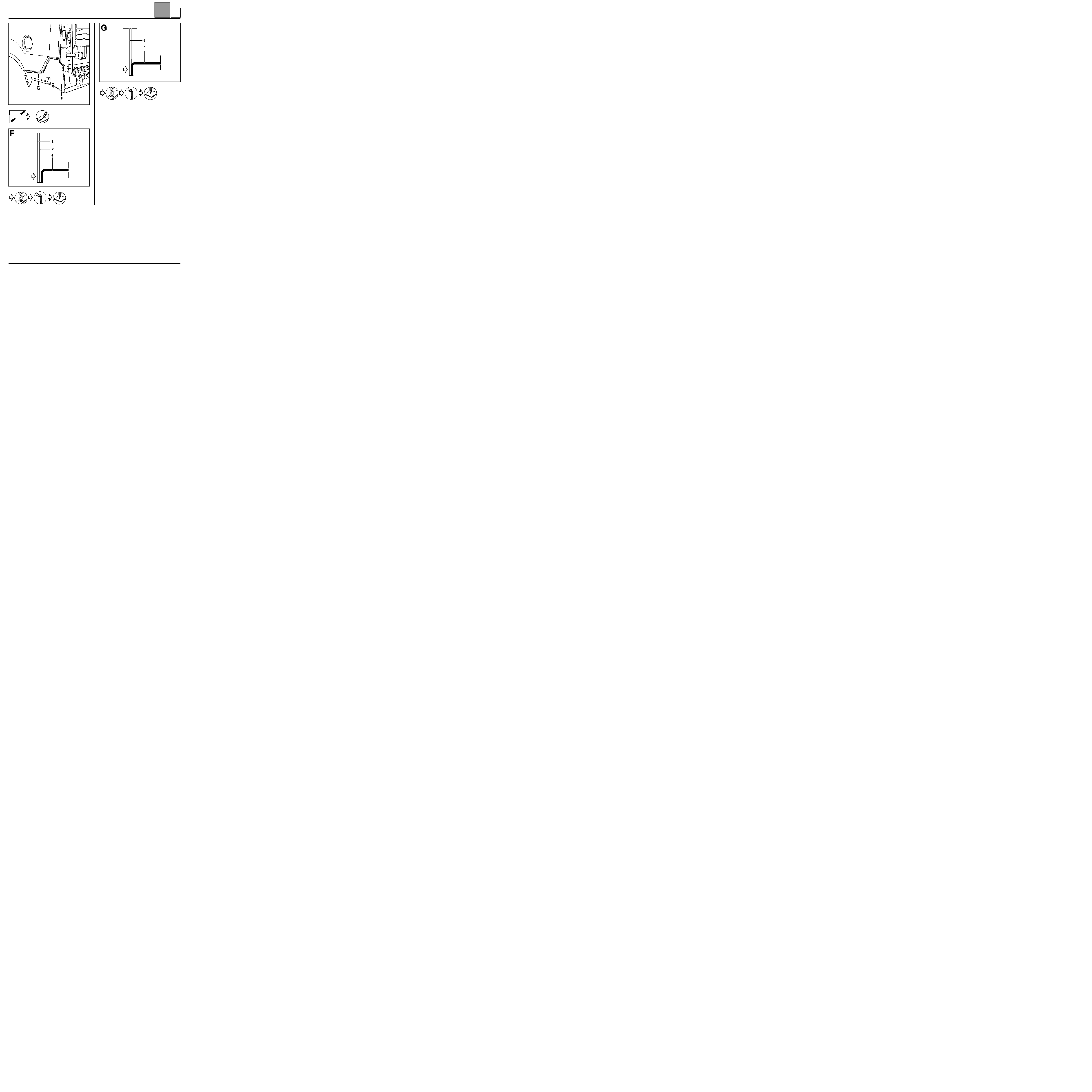
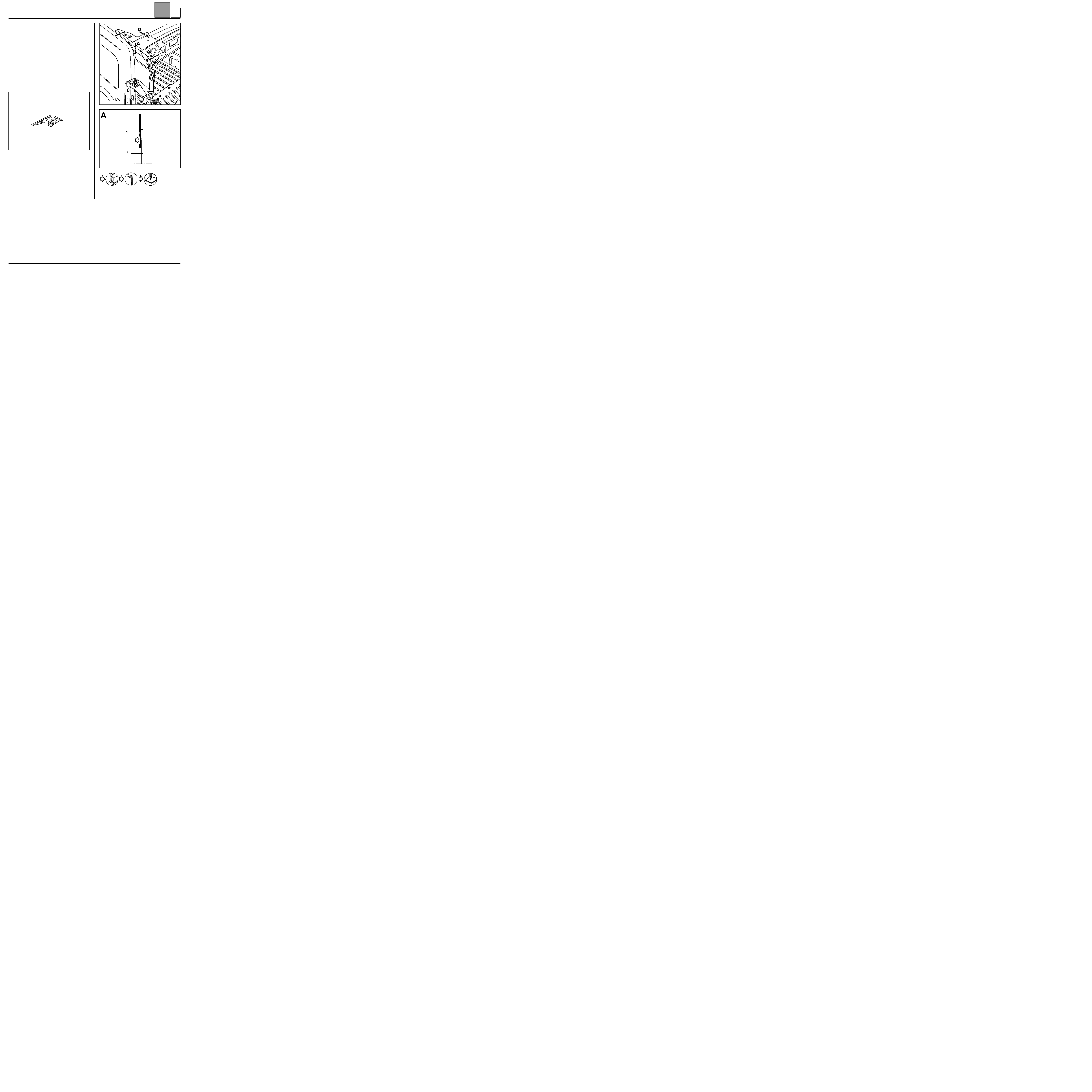
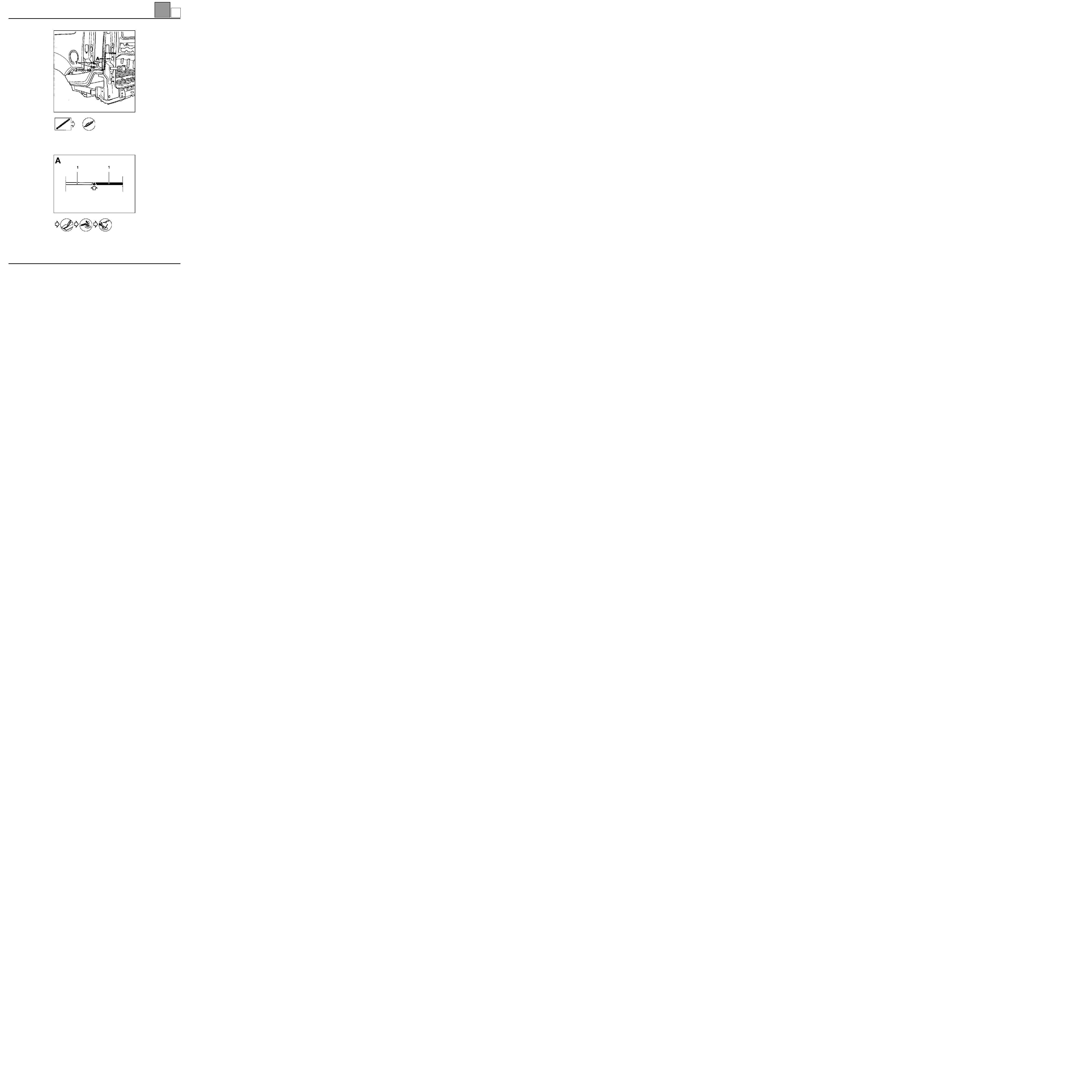
Lights mounting side panel rain channel
INTRODUCTION
This part is changed in addition to changing the
rearend panel. It is carried out partially.
In the operation described below, only descriptions of
the joints specific to the part concerned are given.
Information on parts to which this is additional, will be
dealt with in their respective sections (refer to
contents).
COMPOSITION OF THE PART FROM THE PARTS
DEPARTMENT
Part assembled with:
– side panel extension,
– lights mounting with studs and welded nuts,
– bumper counter blade,
– tailgate counter balance reinforcement,
– welded nuts,
– upper hinge reinforcement.
IMPORTANT: the Parts Department part should be cut
out before fitting at the level of the assembled side
panel extender (refer to diagram below).
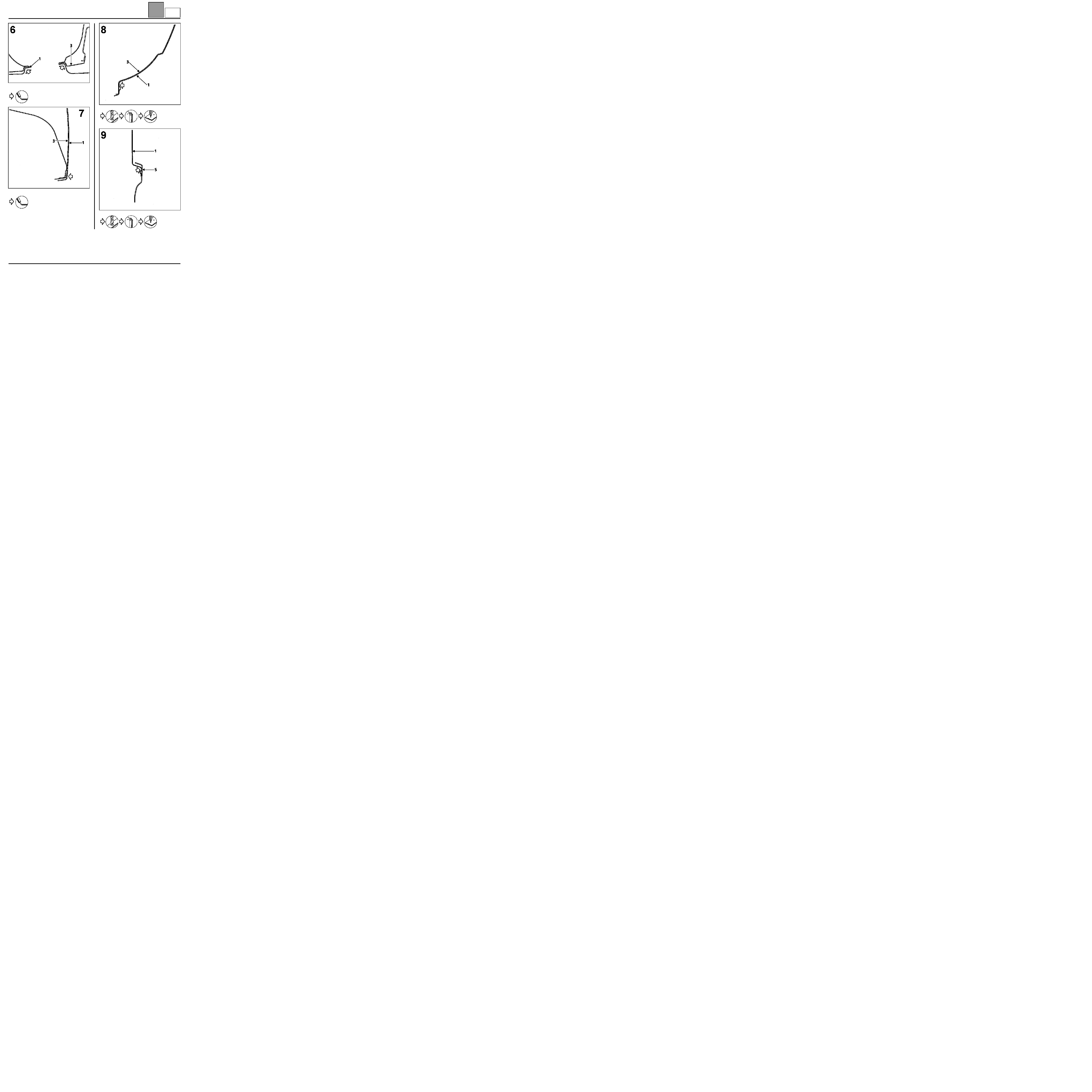
PARTS CONCERNED (thickness in mm):
1 Lights support side panel rain channel
1.5
2 Bolt diameter 8 mm key of 13
3 Steel rivet
16715S
44-33
K
UPPER REAR STRUCTURE
Lights mounting side panel rain channel
44
44-34
REMOVAL - REFITTING
1
Remove the two bolts
2
Bore the rivet
16627R
CAS13033R5
K
TOP OF BODY
Grand volume added roof
45
145
TOP OF BODY
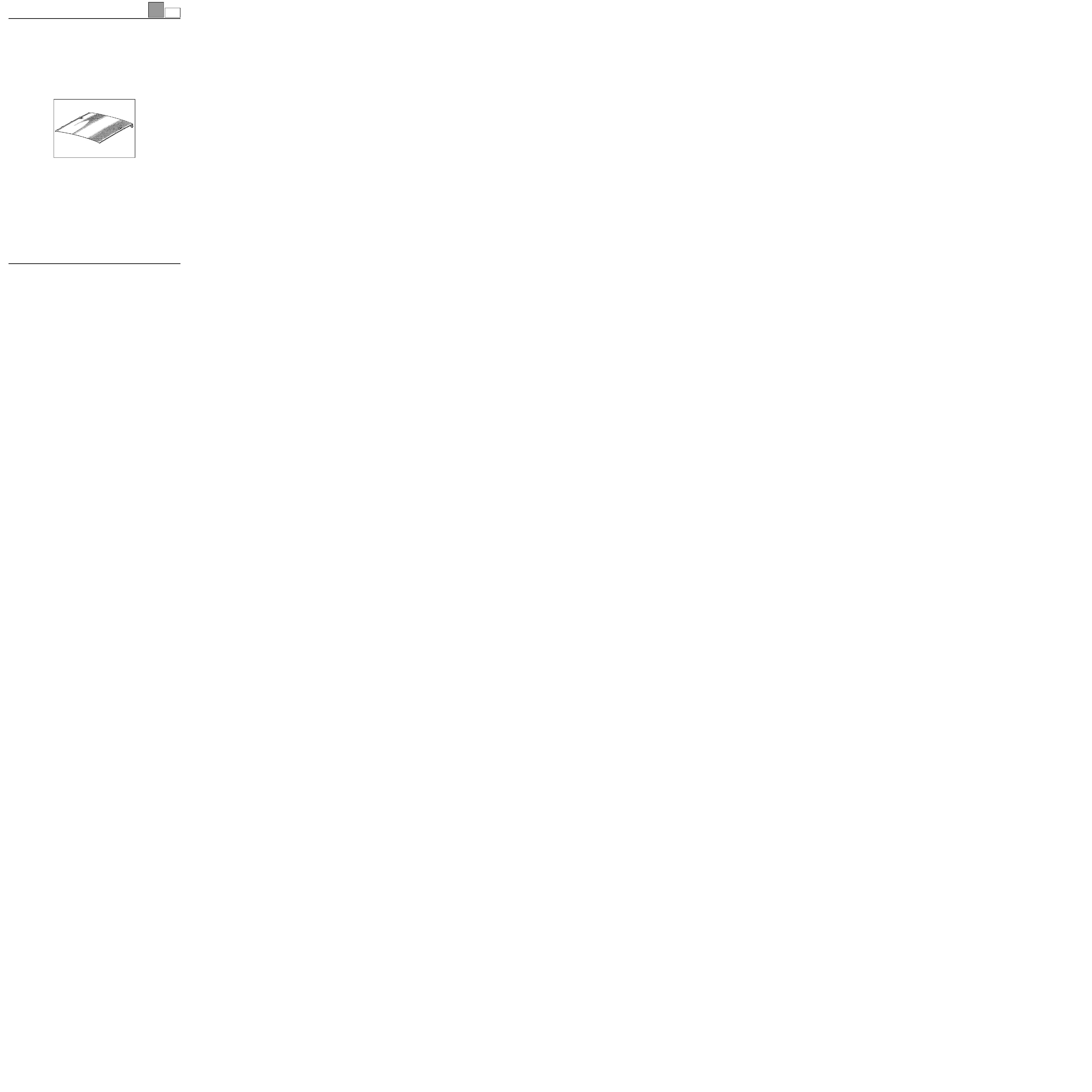
Grand volume added roof
INTRODUCTION
The replacement of this part is a basic operation for a
side impact.
In the operation described below, only descriptions of
the joints specific to the part concerned are given.
Information on additional parts will be dealt with in their
respective sections (refer to the contents).
COMPOSITION OF THE PART FROM THE PARTS
DEPARTMENT
Part provided with luggage grid spacer extractors and
blanking covers.
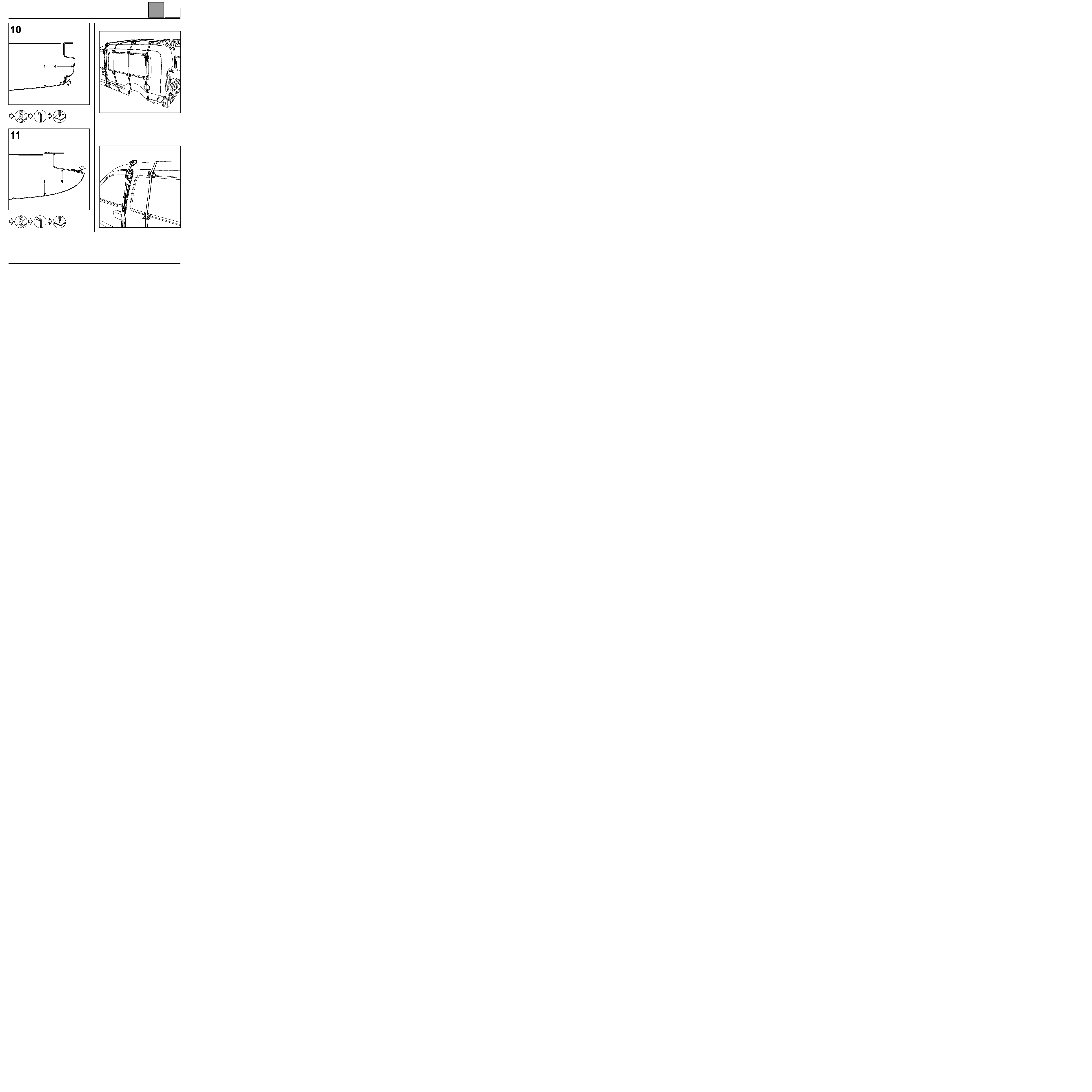
PARTS CONCERNED (thickness in mm):
1 Added roof
0.7
2 Added side panel
0.8
3 Basic body roof
0.8
4 Roof rear cross member
0.8
5 Luggage grid spacer extractor
15
6 Upper rear corner stiffener
1
45-1
Aa

TOP OF BODY
Grand volume added roof
45
45-2
REMOVAL - REFITTING
Moulding ∅ 5 mm
Moulding ∅ 5 mm
Moulding ∅ 5 mm
765A2-16625
16584R
Between sheets (1)
and (2)
16582R
Between sheets (1)
and (3)
Aa

TOP OF BODY
Grand volume added roof
45
45-3
Moulding ∅ 5 mm
Moulding ∅ 5 mm
Moulding ∅ 5 mm
765A1-16626
16586R
A
Between sheets (1)
and (2)
B
Between the sheet
(1) and the part (5)
16583R
Between sheets (1)
and (4)
Aa

TOP OF BODY
Grand volume added roof
45
45-4
Apply a coating of glue to the spacer extractor on (1),
tighten it manually until the two sheets are plated, then
finish by tightening with a key - tightening torque
2.37 da N.m.
Apply a coating of glue on (2) before refitting the
added roof.
Example of plating method for refitting the added roof.
16829R
16633S
Aa
TOP OF BODY
Roof inner panel extender
45
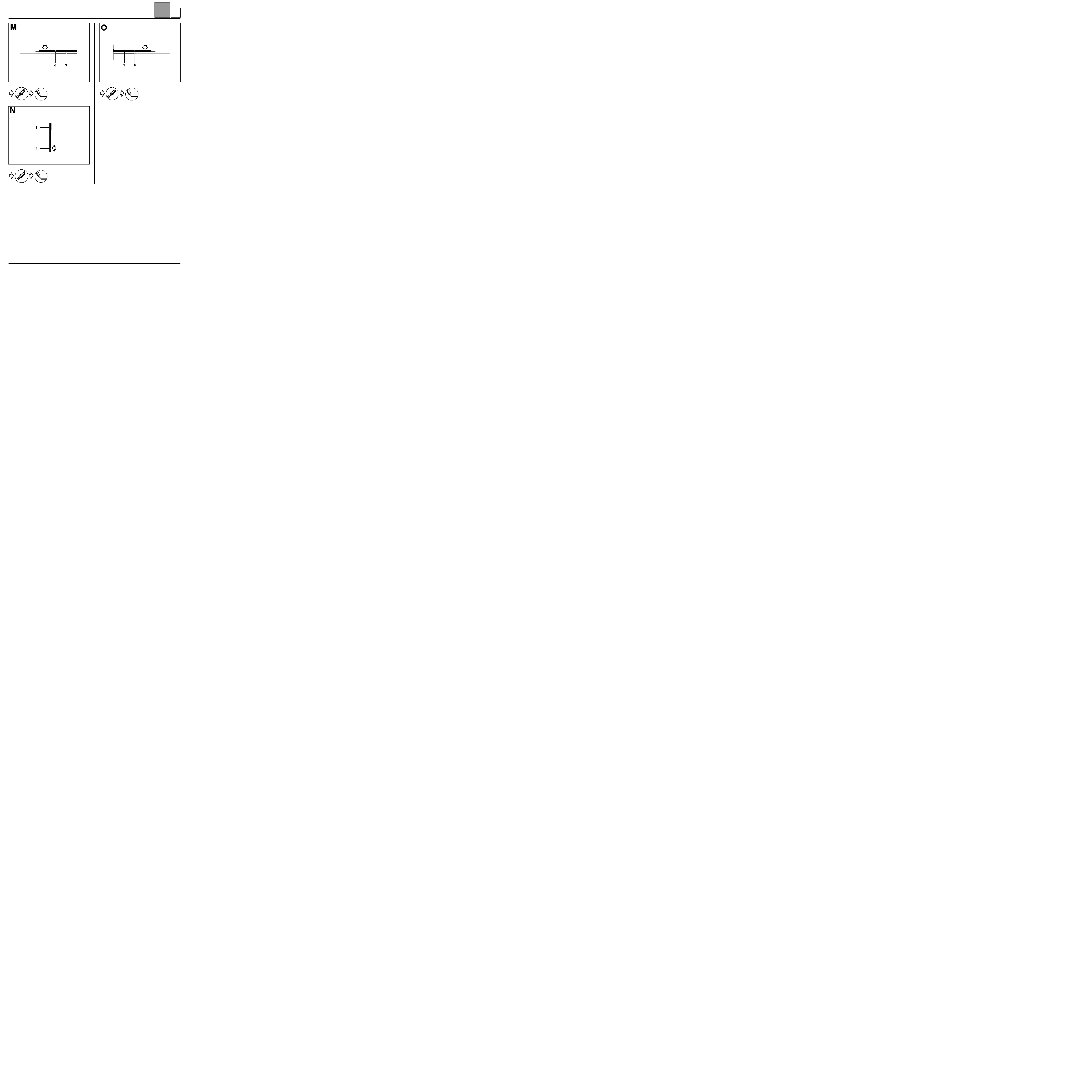
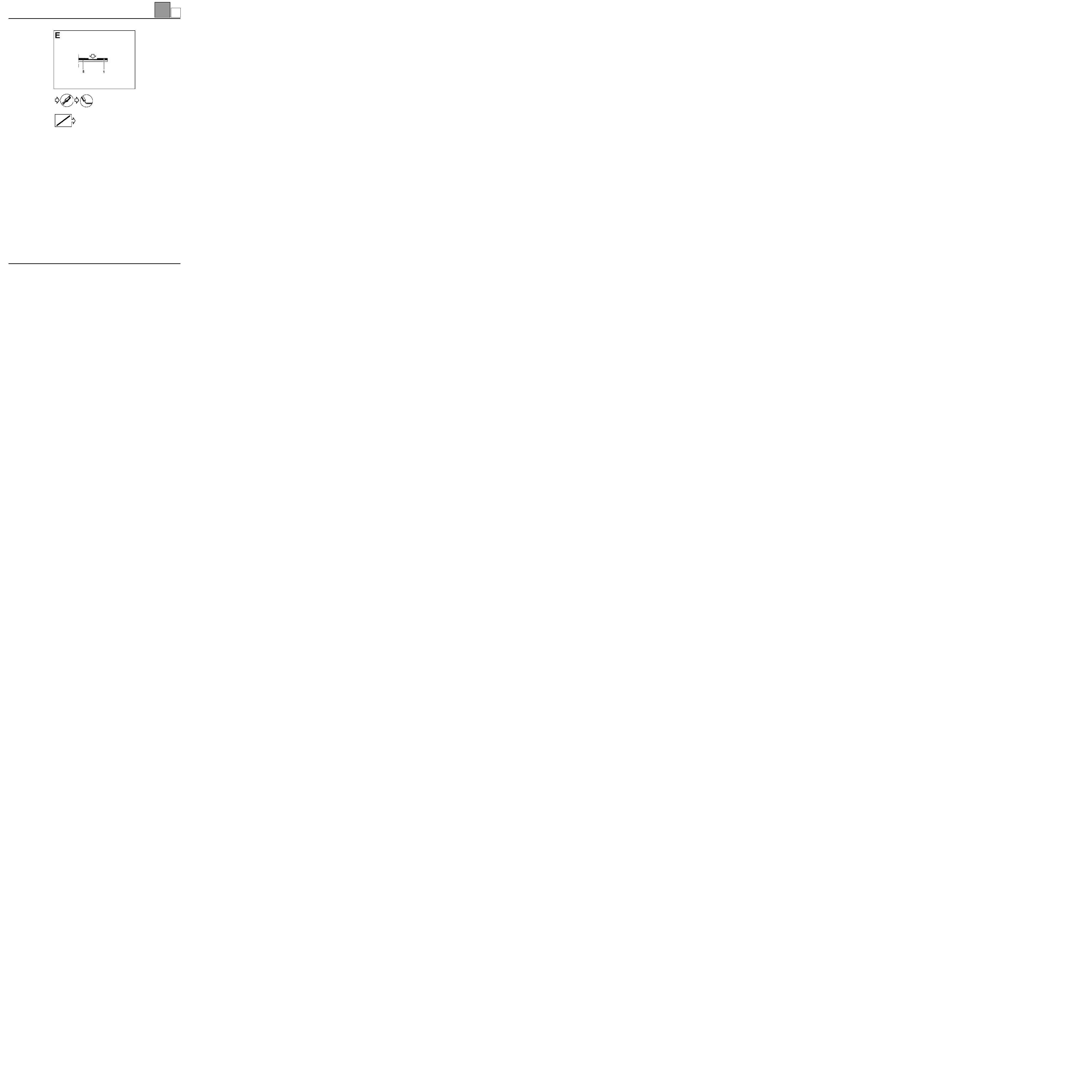
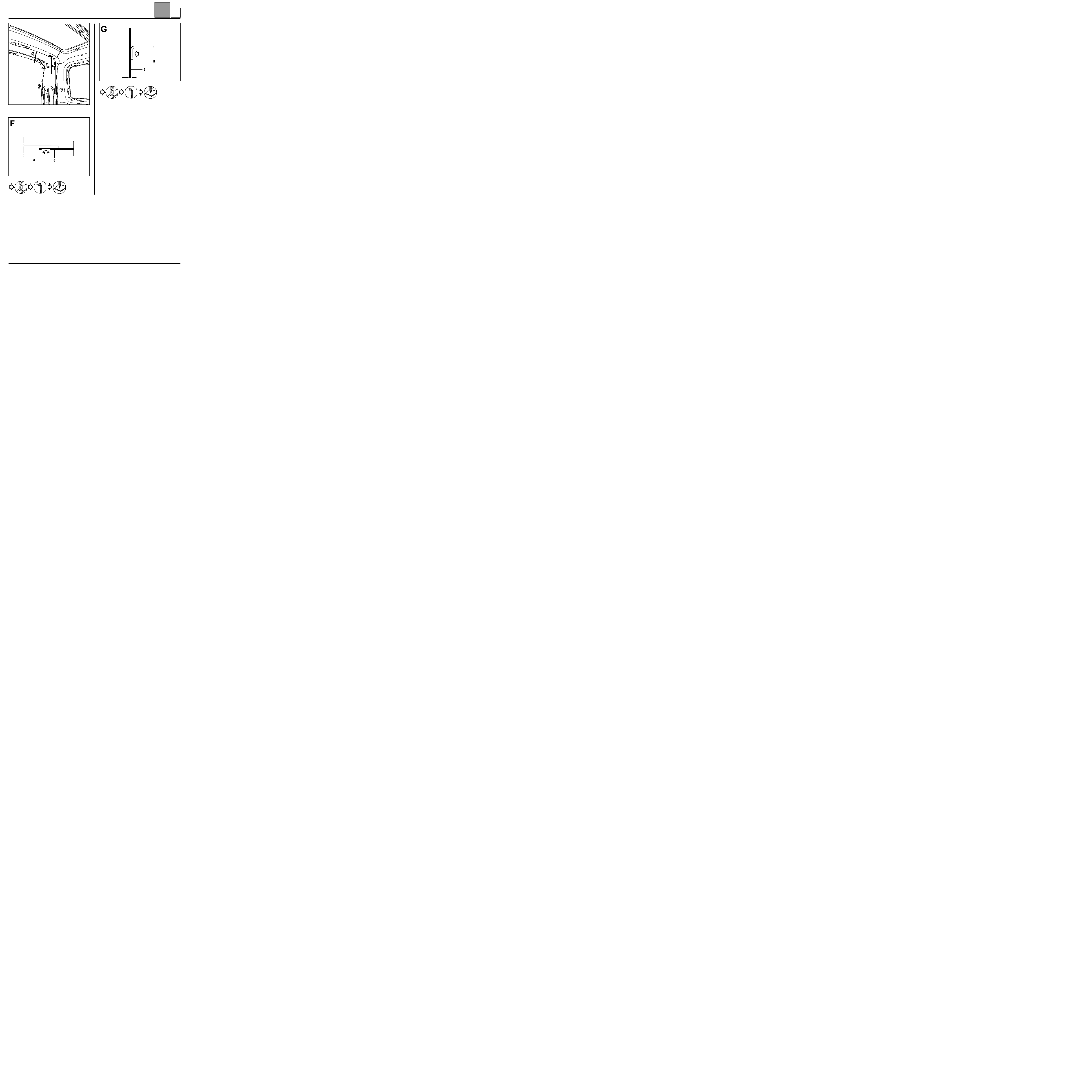
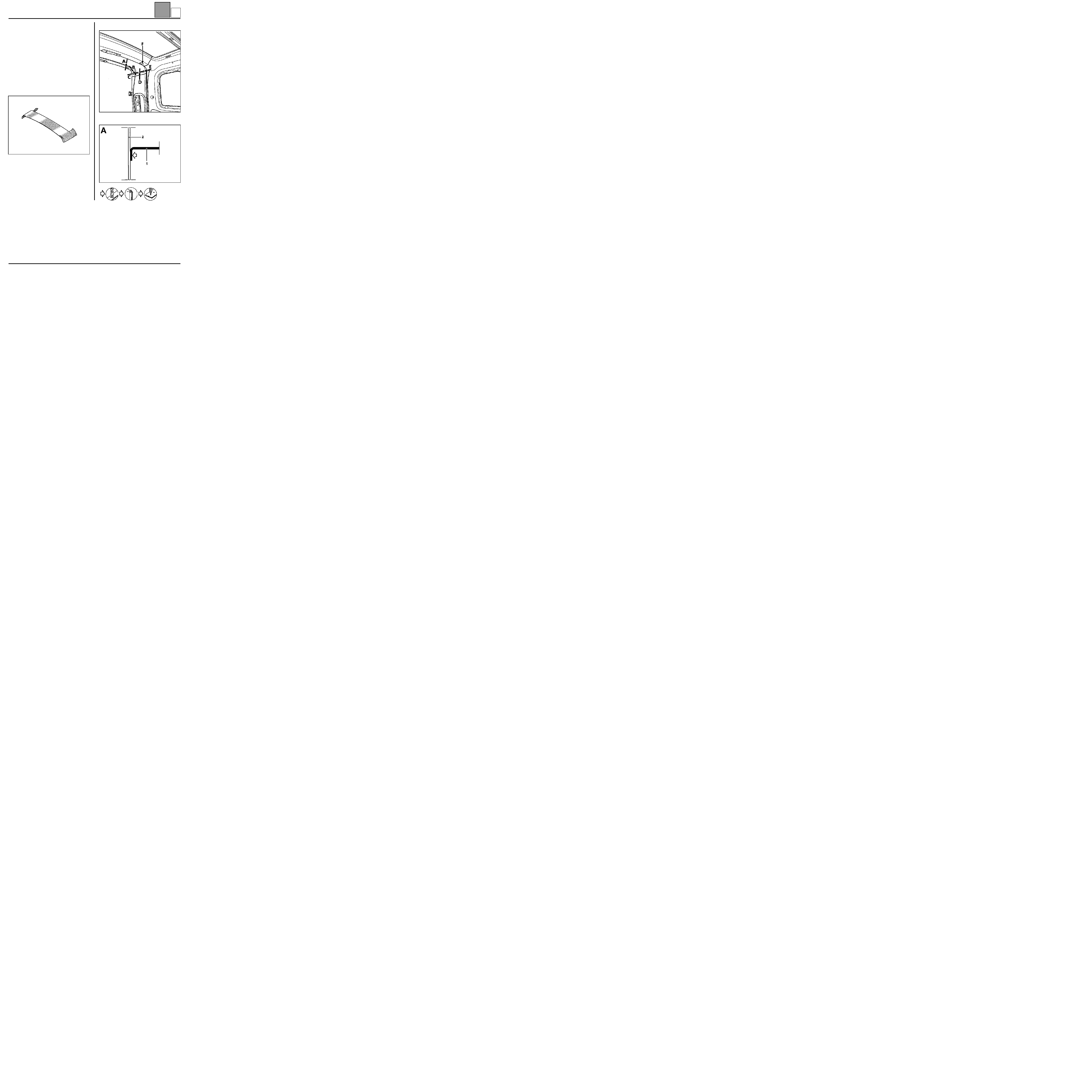
Roof inner panel extender
INTRODUCTION
This part is changed in addition to changing roof with
cross member.
In the operation described below, only descriptions of
the joints specific to the part concerned are given.
Information on parts to which this is additional, will be
dealt with in their respective sections (refer to
contents).
COMPOSITION OF THE PART FROM THE PARTS
DEPARTMENT
Part on its own.
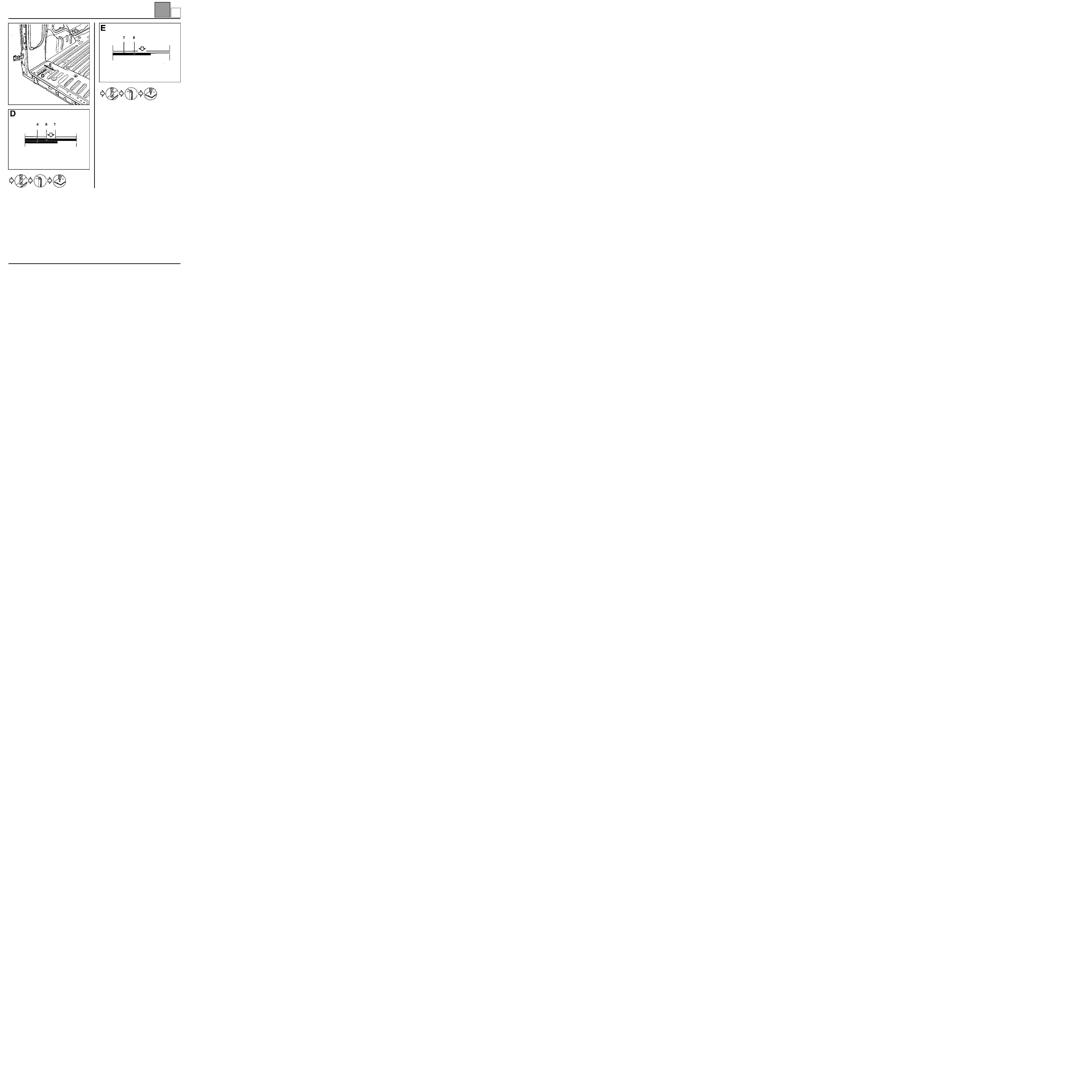
PARTS CONCERNED (thickness in mm):
1 Roof inner panel extender
1
2 Roof rear cross member
0.8
3 Lights support side panel rain channel
1.5
4 Side inner panel extender
0.8
5 Side panel lining
0.7
REMOVAL
F = bolt of Ø 8 mm
765E1-16643
CAA11538R8
45-5
E

TOP OF BODY
Roof inner panel extender
45
45-6
Moulding ∅ 5 mm
CAA11536-2R5
CAB11539-1R1
CAA11536-2R5
between sheets (1)
and (5)
E
Document Outline
- EXPLODED VIEW
- Contents
- 40-GENERAL INFORMATION
- 41-LOWER STRUCTURE
- 44-UPPER REAR STRUCTURE
- 45-TOP OF BODY
Wyszukiwarka
Podobne podstrony:
MR 326 KANGOO 7
MR 326 KANGOO RX4 1
MR 326 KANGOO 6
MR 326 KANGOO 5
MR 325 KANGOO 3
MR 325 KANGOO 8
MR 325 KANGOO 0
MR 325 KANGOO 6
MR 325 KANGOO 3
MR 325 KANGOO 8
MR 325 KANGOO 0
więcej podobnych podstron