Chassis
GENERAL
FRONT AXLE
REAR AXLE
WHEELS AND TYRES
STEERING ASSEMBLY
MECHANICAL ELEMENT CONTROLS
ELECTRONICALLY CONTROLLED SYSTEMS
Renault 1997
77 11 194 253
JULY 1997
Edition Anglaise
"The repair methods given by the manufacturer in this document are based on the
technical specifications current when it was prepared.
The methods may be modified as a result of changes introduced by the
manufacturer in the production of the various component units and accessories
from which his vehicles are constructed."
All copyrights reserved by Renault.
Copying or translating, in part or in full, of this document or use of the service part
reference numbering system is forbidden without the prior written authority of
Renault.
C
FC0A - FC0C - FC0D - FC0E - KC0A - KC0C - KC0D - KC0E
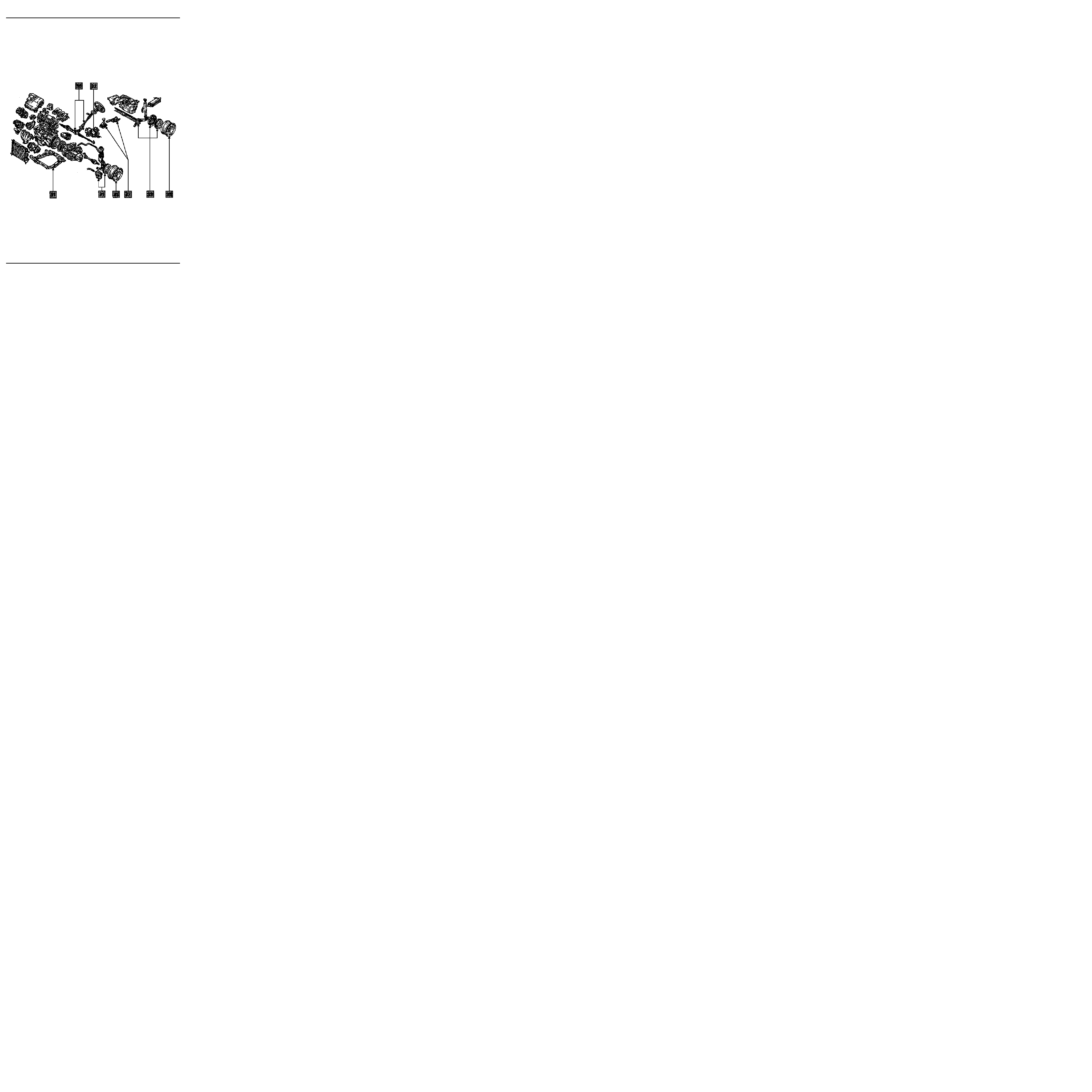
EXPLODED VIEW
PRN3000
Contents
Page
Chassis
GENERAL
General diagram of braking circuits
Tightening torques (in daN.m)
Dimensions of the main braking
components
Bar specifications:
-
front anti-roll bar
-
rear anti-roll bar
-
rear suspension bars
Brake unions and pipes
Brake fluid
30
30-1
30-2
30-7
30-8
30-8
30-8
30-9
30-9
31-1
31-2
31-3
31-4
31-5
31-6
31-7
31-9
31-10
31-12
ENSEMBLE MOTEUR ET BAS
Lower wishbone
Lower wishbone rubber bushes
Lower wishbone ball joint
Brake pads
Front brake calipers
Brake discs
Stub axle carrier bearing
Spring and shock absorber assembly
Anti-roll bar
Engine sub-frame
FRONT AXLE
31
35-1
35-4
Specifications
Wheel balancing
WHEELS AND TYRES
35
33-1
33-2
33-4
33-5
33-7
33-8
33-9
33-10
33-11
33-15
33-16
33-20
Rear axle assembly
Brake drum
Brake cylinder
Brake linings (drum)
Bearing
Shock absorber
Anti-roll bar, tubular rear axle
Half suspension arms, tubular rear
axle
Bushes, tubular rear axle
Suspension bars, tubular rear axle
Four bar rear axle
Suspension arm bearings
REAR AXLE
33

Master cylinder
Brake servo
Air filter - Brake servo non-return
valve
Vacuum pump
Handbrake control lever
Handbrake control
Brake pipes
Braking compensator
Clutch control cable
Clutch automatic wear take-up
system
External gear control
37-1
37-3
37-5
37-6
37-7
37-8
37-10
37-11
37-22
37-23
37-24
Contents
Page
MECHANICAL ELEMENT CONTROLS
37
38-1
38-2
38-3
38-4
38-5
38-6
38-7
38-8
38-9
BOSCH ABS
Presentation of BOSCH ABS 5.3
Location of components
Presentation of the hydraulic
regulation assembly
Wiring diagram
Wiring diagram key
31 track connector
Diagnostic socket
Hydraulic assembly
Hydraulic braking test
ELECTRONICALLY CONTROLLED
HYDRAULIC SYSTEMS
38
STEERING ASSEMBLY
Axial ball joint
Manual steering rack
Power assisted steering rack
Gaiter
Steering rack pinion
Manual steering assistance pump
Steering column
36-1
36-3
36-4
36-6
36-7
36-8
36-12
36

91563S
GENERAL
General diagram of braking circuits
30
NOTE : the diagram below shows the general principle ; in no case should it be taken as reference for the
circuit connections and allocations. When replacing one of the components of the brake circuit on a vehicle,
always mark the pipes before removing them so that they can be connected back in their original positions.
"X" PATTERN BRAKING
with load sensitive compensator
30-1

GENERAL
Tightening torques (in daN.m)
30
F R O N T
AXLE
DI3035R
30-2
GENERAL
Tightening torques (in daN.m)
30
F R O N T
AXLE
DI3034R1
*
Fitting direction must be observed
30-3
GENERAL
Tightening torques (in daN.m)
30
TUBULAR
REAR AXLE
88507-1R2
30-4
GENERAL
Tightening torques (in daN.m)
30
4 BAR
REAR AXLE
88507-2R2
30-5
GENERAL
Tightening torques (in daN.m)
30
D I M E N S I O N S
TIGHTENING TORQUES
Bleed screw
Hoses for front calipers
Hoses on rear suspension arm
Rear wheel cylinder supply
Master cylinder outlets
Compensator inlet
Compensator outlets
-
M 10
×
100
M 10
×
100
M 10
×
100
or
M 12
×
100
M 10
×
100
or
M 12
×
100
M 10
×
100
or
M 12
×
100
M 10
×
100
or
M12
×
100
0.6 to 0.8
1.7
1.7
1.7
1.7
1.7
1.7
30-6
FRONT BRAKES
(in mm)
Diameter of wheel cylinders
Diameter of discs
Thickness of discs
Minimum disc thickness
Pad thickness (including backing)
Minimum pad thickness (including backing)
Maximum disc run-out
REAR BRAKES
(in mm)
Diameter of wheel cylinders
Diameter of drums
Maximum drum wear diameter
Diameter of discs
Thickness of discs
Minimum disc thickness
Lining size
Secondary
Lining thickness (including backing)
Primary
Minimum lining thickness (including backing)
MASTER CYLINDER
(in mm)
Diameter
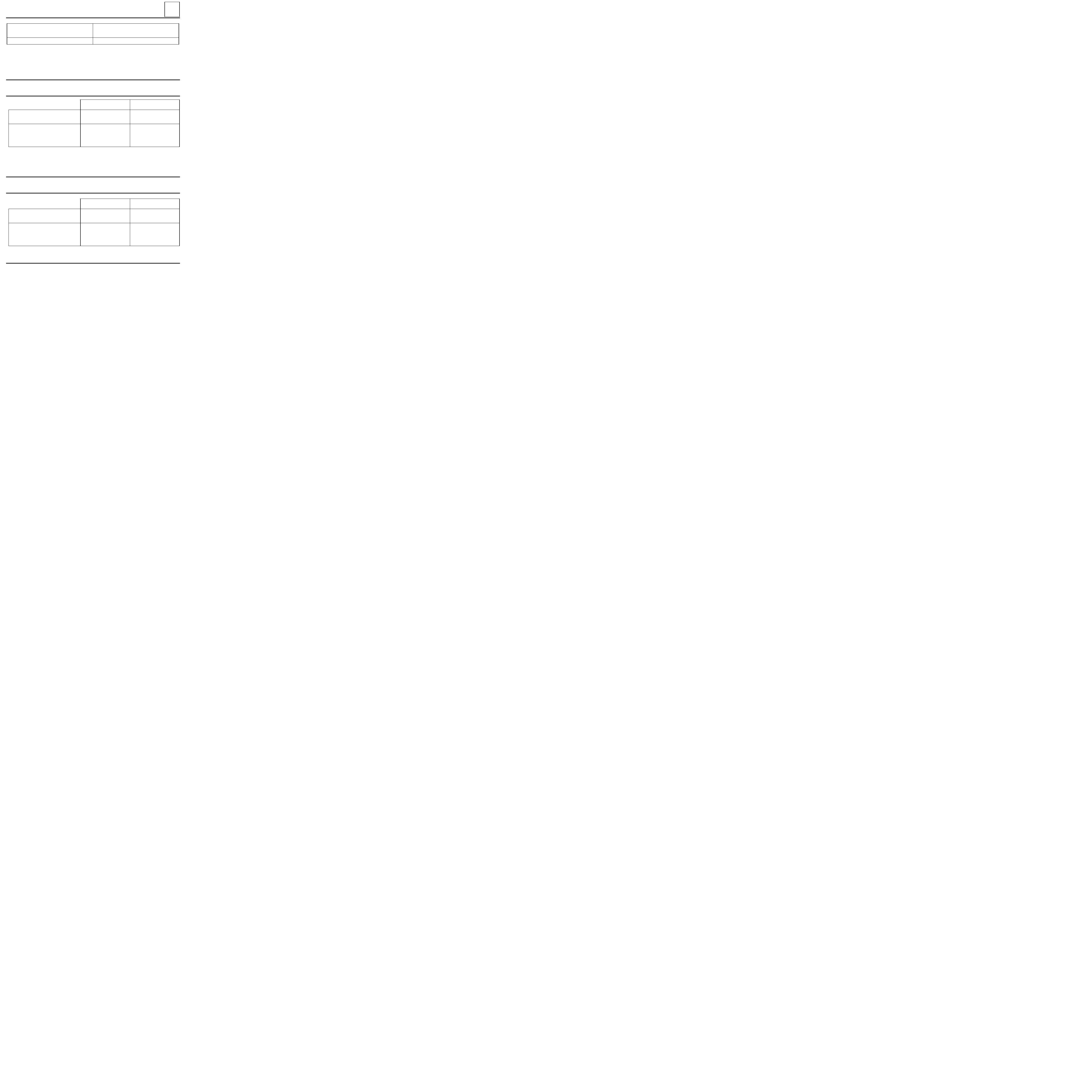
GENERAL
Dimensions of the main braking components
30
F C 0 X
K C 0 X
CUS
F C 0 X
K C 0 X
CUA
54
238.2
20
17.7
17.8
5.5
0.07
22
203.2
204.45
-
-
-
38
3.15 (ABS) - 2.8(no ABS)
4.6 (ABS) - 4.2(no ABS)
2
22.2
54
238.2
20
17.7
17,8
5.5
0.07
22
228.3
229.5
-
-
-
40
4.8 (ABS) - 4.5(no ABS)
2
22.2
CUS
:
Standard payload
CUA
:
Increased payload
30-7
GENERAL
Front anti-roll bar specifications
30
VEHICLE TYPE
F C 0 X
K C 0 X
DIAMETER
(in mm)
23
Rear anti-roll bar specifications
Rear suspension bar specifications
VEHICLE TYPE
F C 0 X
K C 0 X
F C 0 X
K C 0 X
DIAMETER
(in mm)
NUMBER OF SPLINES, BEARING SIDE
NUMBER OF SPLINES, SHACKLE SIDE
18
-
-
26.4
30
31
TUBULAR REAR AXLE
4 BAR REAR AXLE
VEHICLE TYPE
F C 0 X
K C 0 X
F C 0 X
K C 0 X
DIAMETER
(in mm)
NUMBER OF SPLINES, BEARING SIDE
NUMBER OF SPLINES, SHACKLE SIDE
22.1
30
31
25.5
30
31
TUBULAR REAR AXLE
4 BAR REAR AXLE
30-8
Brake fluid
78491R
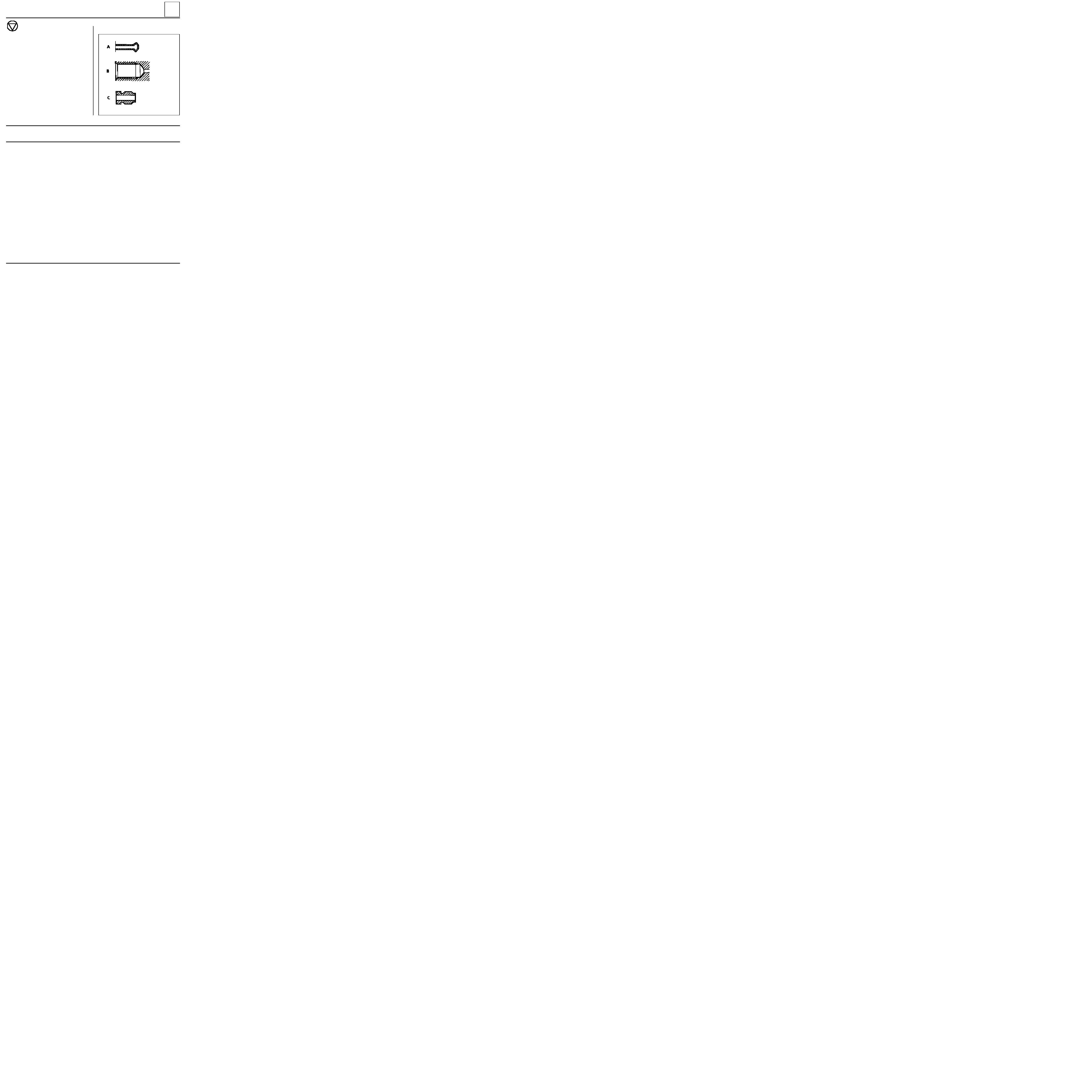
GENERAL
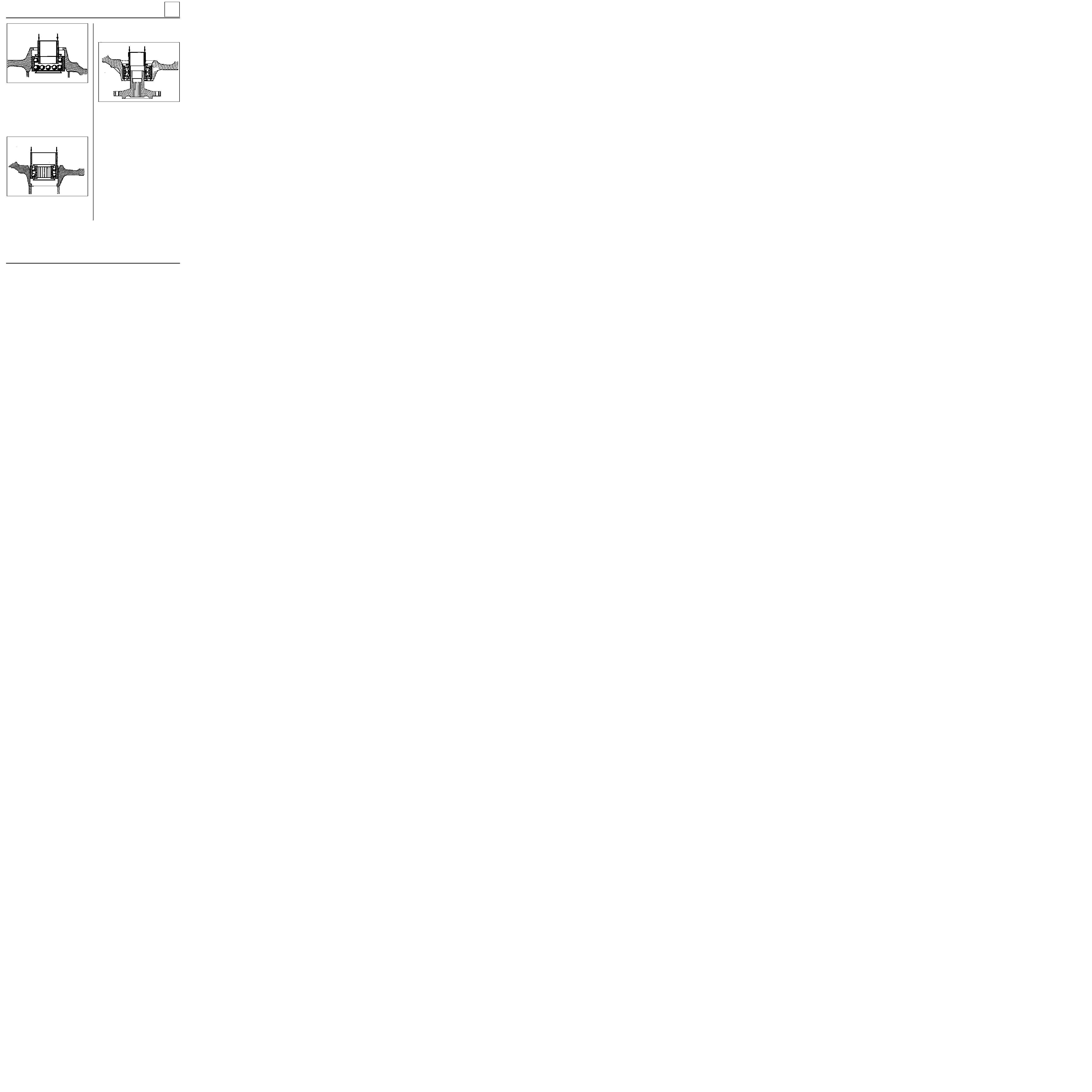
Brake unions and pipes
30
The connection of the pipes between the master
cylinder, calipers, compensator and the hydraulic
assembly is made using threaded unions with a
METRIC THREAD.
Consequently, only parts specified in the Parts
Catalogue for this vehicle should be used.
Identification of parts
-
SHAPE of the ends of PIPES in steel or copper
(A),
-
SHAPE of the THREADED LOCATIONS on
components (B),
-
pipe UNIONS coloured GREEN or BLACK:
HEXAGONAL OUTSIDE 11 mm or 12 mm (C).
BRAKE FLUID RENEWAL FREQUENCY
Braking technology, in particular for disc brakes (hollow pistons which transmit little heat, low volume of
fluid in the cylinder, sliding calipers avoiding the need for a fluid reservoir in the least cooled area of the
wheel), has allowed us to avoid the risk of vapour lock as far as possible, even if the brakes are used
intensively (in mountainous areas).
Modern brake fluids still degrade slightly during the first few months of use due to a small uptake of
humidity and replacement of the fluid is therefore recommended (refer to vehicle’s Warranty and Servicing
Handbook).
Topping up the level:
Wear of the brake pads and shoes will cause a gradual drop in the fluid level in the reservoir. This drop should
not be compensated for since the level will rise again when the pads are changed. The level should not
however be allowed to fall below the minimum mark.
Approved brake fluids:
Mixing two incompatible brake fluids in the circuit will cause a risk of major leaks, mainly due to
deterioration of the cups. To avoid such risks, it is important to use only those brake fluids which have been
tested and approved by our Technical Department and which conform to standard SAE J 1703 dot 4.
30-9

FRONT AXLE
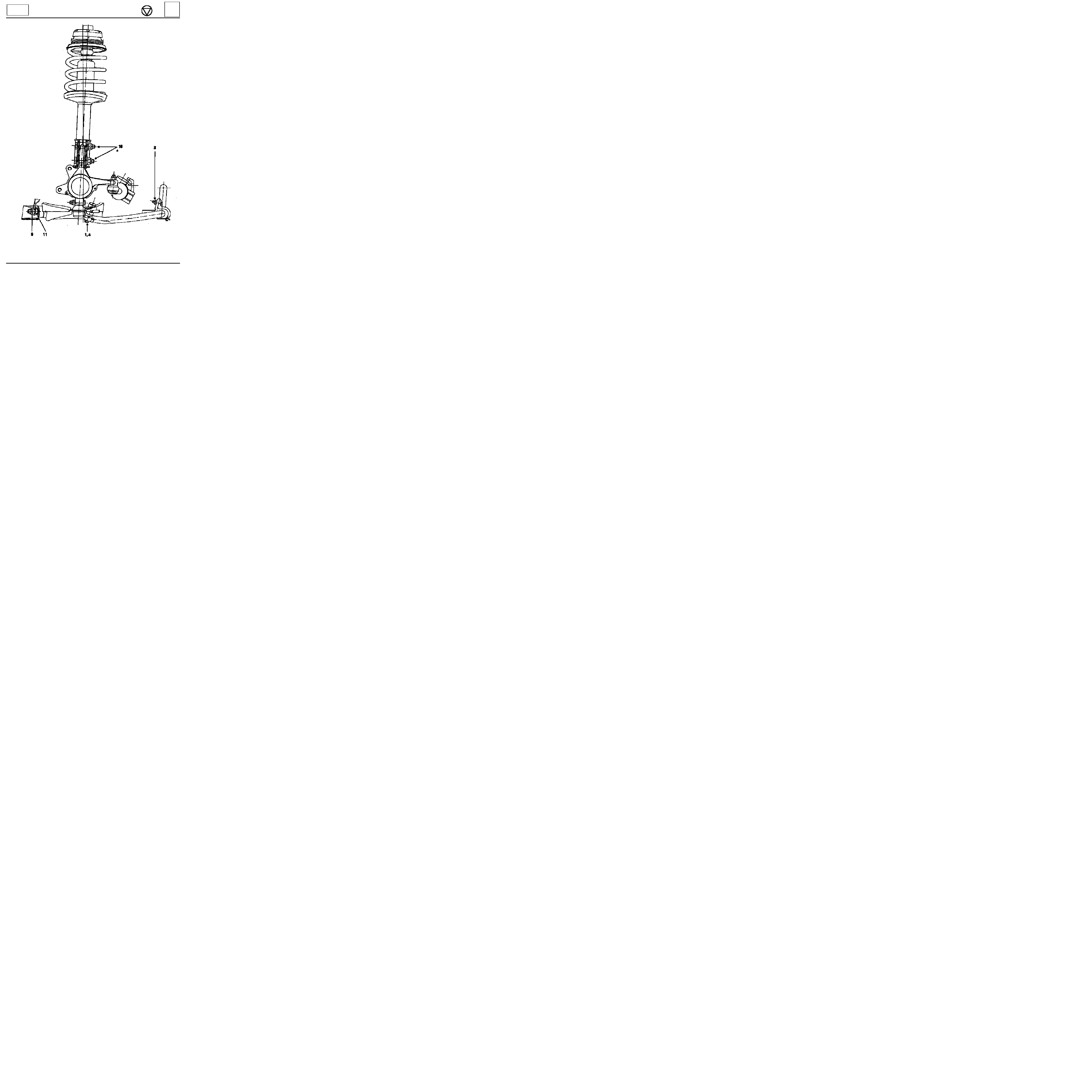
Lower wishbone
31
85875R2
12992R
Wheel bolts
9
Lower wishbone nut on sub-frame
9
Key nut on stub-axle carrier
5.5
Anti-roll bar bearing nut
1.5
TIGHTENING TORQUES (in daN.m)
REMOVAL
Put the vehicle on a two post lift.
Remove both wheels.
Remove the mounting nuts for the anti-roll bar on
the lower wishbones.
Release the anti-roll bar downwards.
Remove:
- the nut and key on the stub-axle carrier,
- the two mounting bolts for the wishbone on
the sub-frame,
- the wishbone.
REFITTING
NOTE :
ensure the plastic protective washer ( A ) is
present on the lower ball joint shaft.
Refit:
-
the wishbone,
-
the two bolts, without tightening them,
-
the ball joint shaft in the stub-axle carrier and
tighten the key nut.
Refit the anti-roll bar and fit the mounting nuts
using tool Sus. 1414 (see method in anti-roll bar
section).
This tool allows the rubber mounting to be
compressed to fit the nut.
NOTE :
bounce the suspension and tighten the
wishbone and anti-roll bar bearing nuts to the re-
commended torque (tightening position: vehicle
unladen).
31-1

FRONT AXLE
Lower wishbone rubber bushes
31
90404R
REPLACEMENT
To ensure the bushes are correctly positioned in
relation to the lower wishbone, they are replaced
one after the other.
On the press, remove one of the worn bushes
using a tube of external diameter 30 mm.
Refit the new bush, ensuring that dimension A =
146.5 mm
.
Remove the second bush on the press and proceed
in the same manner as for the first bush, ensuring
the new bush is fitted so that dimension A =
146.5 mm
.
31-2
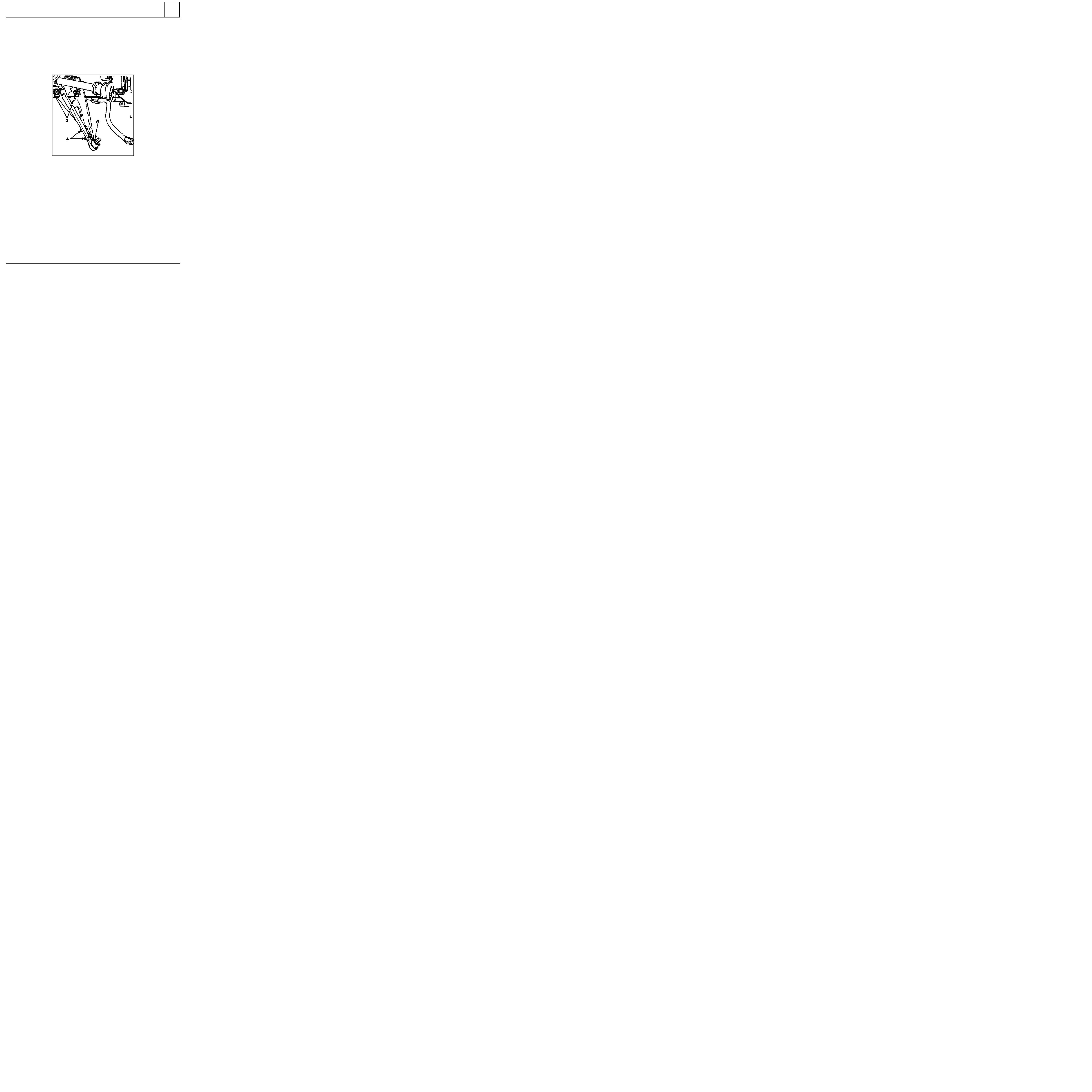
FRONT AXLE
Lower wishbone ball joint
31
85875R1
Remove
:
-
the two ball joint mounting bolts (4) ,
-
the ball joint.
REFITTING
Note : ensure the plastic protective washer ( A ) is
present on the lower ball joint shaft.
Fit the ball joint and torque tighten the
mountings.
Then proceed in the same manner as for refitting
the lower wishbone.
REMOVAL
If the gaiter is damaged, the complete ball joint
must be replaced.
Proceed in the same manner as for removing the
lower wishbone.
Slacken but do not remove the two mounting
bolts (3) for the wishbone on the sub-frame.
31-3

FRONT AXLE
Brake pads
31
REMOVAL
Disconnect the wear warning light wire (if fitted).
Push the piston back, sliding the caliper by hand.
Remove the lower brake caliper guide bolt.
SPECIAL TOOLING REQUIRED
Fre. 823
Tool for pushing piston back
Wheel bolts
9
Brake caliper guide bolt
4
12994R
REFITTING
Push back the caliper piston using tool Fre. 823.
Fit new brake pads.
The brake pad with the wear warning light wire
(if fitted) is fitted to the inside.
Refit the caliper into position and fit the lower
guide bolt.
Tighten the guide bolt to the recommended
torque 4 daN.m.
Reconnect the wear warning light wire (if fitted).
Press the brake pedal several times to bring the
piston into contact with the pads.
TIGHTENING TORQUES (in daN.m)
Pivot the caliper around the upper bolt.
Remove the brake pads.
Check
:
-
the condition and mounting of the piston dust
cover,
-
the condition of the guide dust cover.
31-4
FRONT AXLE
Front brake calipers
31
REPAIR
NOTE :
if there are any scratches in the caliper
bore, the complete caliper must be replaced.
To do this:
-
remove the brake caliper,
-
remove the rubber dust cover,
-
remove the piston using compressed air,
inserting a wooden block between the caliper
and the piston to prevent damage to the
piston: any trace of damage to the piston skirt
will render it unusable
-
remove the seal from the caliper groove using
a flexible rounded edge blade (eg feeler
gauge).
Clean the parts using methylated spirits.
Replace any faulty parts using original parts and
then refit the seal, piston and dust seal.
REMOVAL
In the passenger compartment, fit a pedal press
(limits the amount of brake fluid which will run
out).
Release the brake pipe at the wheel cylinder end.
Remove the brake pads (see previous page).
Remove the two mounting bolts for the caliper on
the stub axle carrier.
Completely release the brake pipe by turning the
caliper.
Check the condition of the pipe and replace it if
necessary.
REFITTING
Fit the pipe onto the caliper.
Remove the pedal press.
To check the correct operation of the caliper
cylinder, slacken the bleed screw and wait for
brake fluid to run out.
Retighten the bleed screw.
Refit the caliper on the stub axle carrier and
tighten the bolts to the recommended torque.
Refit the pads and the wheel cylinder (follow the
method described previously).
Wheel bolts
9
Brake caliper guide bolt
4
Brake caliper mounting bolt
10
TIGHTENING TORQUES (in daN.m)
31-5

FRONT AXLE
Brake discs
31
Brake discs cannot be reground. If they are too
heavily worn or are scratched they must be repla-
ced.
Wheel bolts
9
Brake caliper mounting bolt
10
REMOVAL
Remove
:
-
the two brake assembly mounting bolts
(attach the assembly to the spring),
-
the two mounting bolts securing the disc to
the hub,
-
the disc.
REFITTING
Refitting is the reverse of removal.
NOTE
: when a brake disc is replaced, the pads
must also be renewed.
TIGHTENING TORQUES (in daN.m)
31-6

FRONT AXLE
Stub axle carrier bearing
31
SPECIAL TOOLING REQUIRED
Rou.
15 -01
Shaft protector
Rou.
604 -01
Hub locking tool
T . A v .
476
Ball joint extractor
T.Av. 1050-02
Tool for pushing driveshaft back
Driveshaft nut
28
Wheel bolts
9
Shock absorber base nut
18
Brake caliper mounting bolt
10
Track rod end nut
3.7
Key nut on stub axle carrier
5.5
83348G
REMOVAL
Disconnect the battery.
Remove:
-
the wheel,
-
the brake caliper and attach it to the spring so
the pipe is not damaged,
-
the track rod end using tool
T.Av. 476
,
-
the driveshaft nut.
Push back the driveshaft using tool :
T. Av. 1050-02
.
Remove
:
-
the brake disc,
-
the lower ball joint nut and key,
-
the two shock absorber base bolts,
-
the hub / stub axle carrier / bearing assembly.
TIGHTENING TORQUES (in daN.m)
Remove the hub on the press.
Remove the lower bush from the hub using an ex-
tractor with jaws and tool Rou. 15-01.
Remove the locking spring ring from the stub axle
carrier.
On the press remove the remainder of the bea-
ring, taking care to take the weight on the inner
bush using a tube of the same diameter.
31-7
FRONT AXLE
Stub axle carrier bearing
31
79057S
REFITTING
Fit the bearing on the press, into the stub axle car-
rier using a tube of external diameter
70 mm
and bore 66 mm, taking the weight on the
external bush.
I M P O R T A N T
: do not take the weight on the inter-
nal bush to avoid damaging the bearing as the
force required to push the bearing on is quite
considerable.
79058-1S
Fit a new locking spring ring.
Coat each sealing lip of the bearing with multi-
purpose grease.
Fit on the press, using a tube of external diameter
48 mm
and internal diameter 42 mm, taking the
weight on the inner bearing bush.
85902S1
Refit the hub / stub axle carrier / bearing assembly
to the vehicle.
Refitting is then the reverse of removal. Observe the
correct tightening torques.
31-8

Spring compressor
FRONT AXLE
Spring and shock absorber assembly
31
Shock absorber base mounting bolt
18
Rebound stop nut
6
Wheel bolts
9
REMOVAL
Put the vehicle on a four post lift.
Remove
:
-
the wheels,
-
the shock absorber base mounting bolts.
NOTE
: release the ABS sensor wiring if this is
fitted on the base of the shock absorber.
Remove the upper shock absorber nut in the
engine compartment.
Remove the shock absorber and spring assembly.
TIGHTENING TORQUES (in daN.m)
EQUIPMENT REQUIRED
Replacing a shock absorber
When replacing a shock absorber, fit it in a vice
and compress the spring using the spring
compressor tool.
Remove the spring retaining nut.
Remove the spring and the intermediate parts.
If necessary, replace the shock absorber pad and
the rotating stop.
When refitting, ensure all components are
replaced in the correct location and then
decompress the spring.
NOTE
: apply grease between the ends of the
spring and its stops.
REFITTING
Refitting is then the reverse of removal. Observe
the correct tightening torques.
31-9
FRONT AXLE
Anti-roll bar
REFITTING
Refit
:
-
the rubber mounting nuts using tool
Sus. 1414
,
31
REMOVAL
Put the vehicle on a four post lift.
Remove
:
-
the two lower bolts from the exhaust
downpipe,
-
the two sub-frame reinforcements (4 bolts),
12993-1R
Central bearing bolt
3
Rubber mounting nut
1.5
TIGHTENING TORQUES (in daN.m)
SPECIAL TOOLING REQUIRED
Sus.
1413
Central bearing compressor
Sus.
1414
Rubber mounting compressor
-
the two rubber mounting nuts at the ends of
the anti-roll bar,
-
the two bolts from the central bearings on the
bar.
Check the condition of the bearings and the
rubber mountings and replace them if necessary.
12992R
31-10

FRONT AXLE
Anti-roll bar
31
-
the central bearing bolts using tool
Sus. 1413
.
12991R
-
the two sub-frame reinforcements,
-
the lower bolts on the exhaust downpipe.
Rubber bush locking position :
U N L A D E N
.
31-11
FRONT AXLE
Engine sub-frame
Remove:
-
the two nuts for the steering rack heat shield,
-
the mounting nuts for the steering rack and
attach it to the exhaust manifold.
31
12988R
SPECIAL TOOLING REQUIRED
Mot.
1040 -01
Dummy sub-frame for removing/refitting engine/transmission assembly
T. Av. 476
Ball joint extractor
REMOVAL
Disconnect the battery.
Put the vehicle on a two post lift.
Remove the wheels.
Disconnect the track rod ends using tool T. Av.
476
.
Remove the key on the stub axle carrier.
Release but do not remove the mudguards to
reach the upper bolt on the sub-frame - side mem-
ber tie rod and remove it.
Remove:
-
the exhaust downpipe and attach the catalytic
converter,
-
the bolt (engine side) for the engine tie bar.
-
the gear control by removing the two bolts at
the ends of the control. To do this, the cataly-
tic converter heat shield must be removed and
the gaiter on the gearbox side must also be re-
moved.
TIGHTENING TORQUES (in daN.m)
Wheel bolts
9
Track rod end nut
3.7
Steering universal joint bolt
2.5
Sub-frame mounting bolt front Ø10 6
rear Ø 12 10.5
Sub-frame - side member tie rod nut
3
Key nut on stub axle carrier
5.5
Engine tie bar
6.5
Steering box mounting bolt
5
Fit tool Mot. 1040-01 under the engine sub-frame.
12993-1R1
31-12

FRONT AXLE
Engine sub-frame
31
Lower the lift until the tool touches the ground.
Remove the sub-frame mounting bolts.
Carefully raise the lift.
REFITTING
Systematically renew the engine sub-frame moun-
ting bolts and ensure they are tightened to the
correct torque.
Refitting is the reverse of removal.
NOTE :
the engine sub-frame is fitted to the body
in the following manner.:
-
fit 2 pins in place of the front mounting bolts,
-
offer up the sub-frame,
-
tighten, but do not lock, the rear mounting
bolts (begin with the longest rear right hand
bolt),
-
replace the pins with mounting bolts at the
front,
-
tighten the four mounting bolts to the correct
torque, beginning at the rear,
-
ensure the heat shields are correctly refitted.
31-13

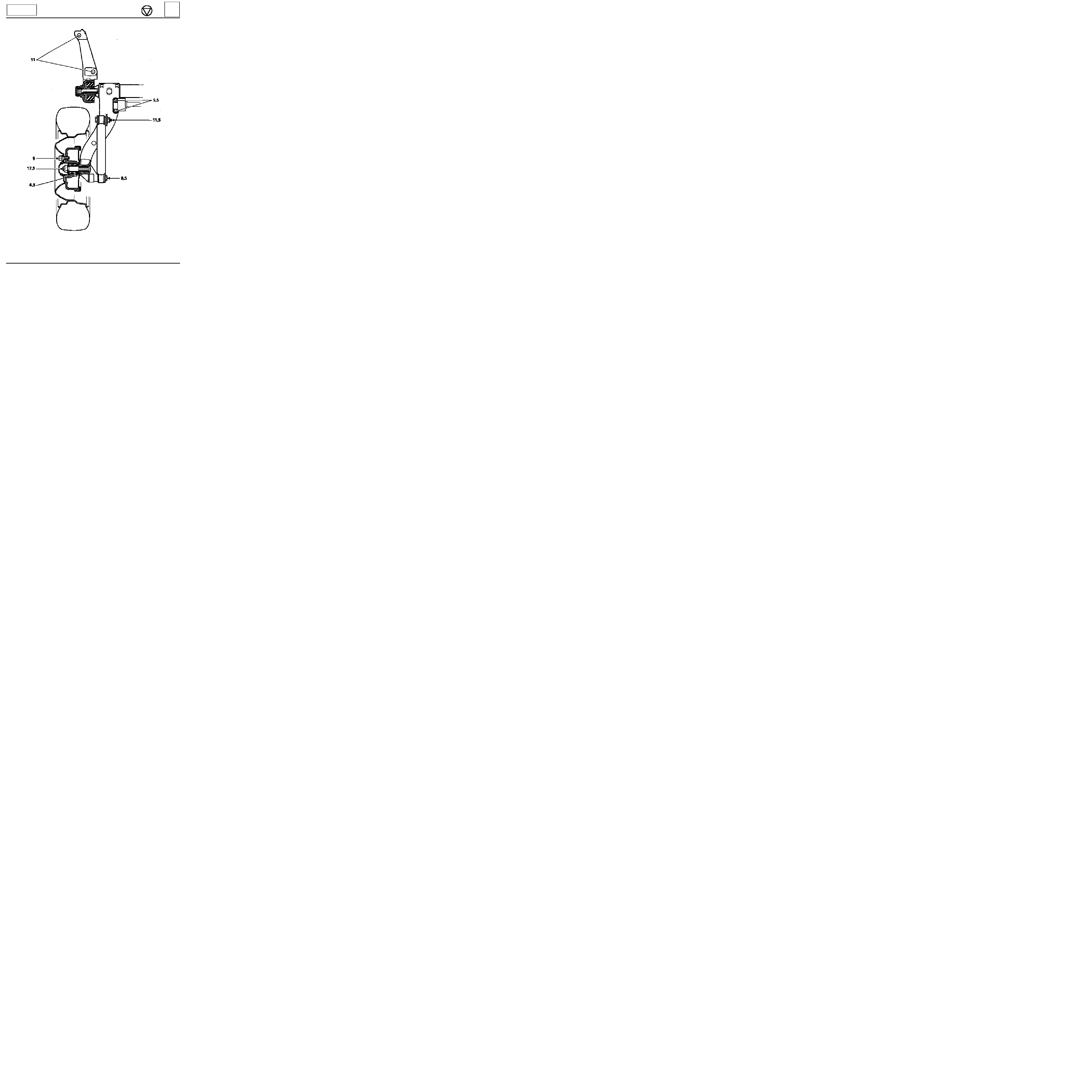
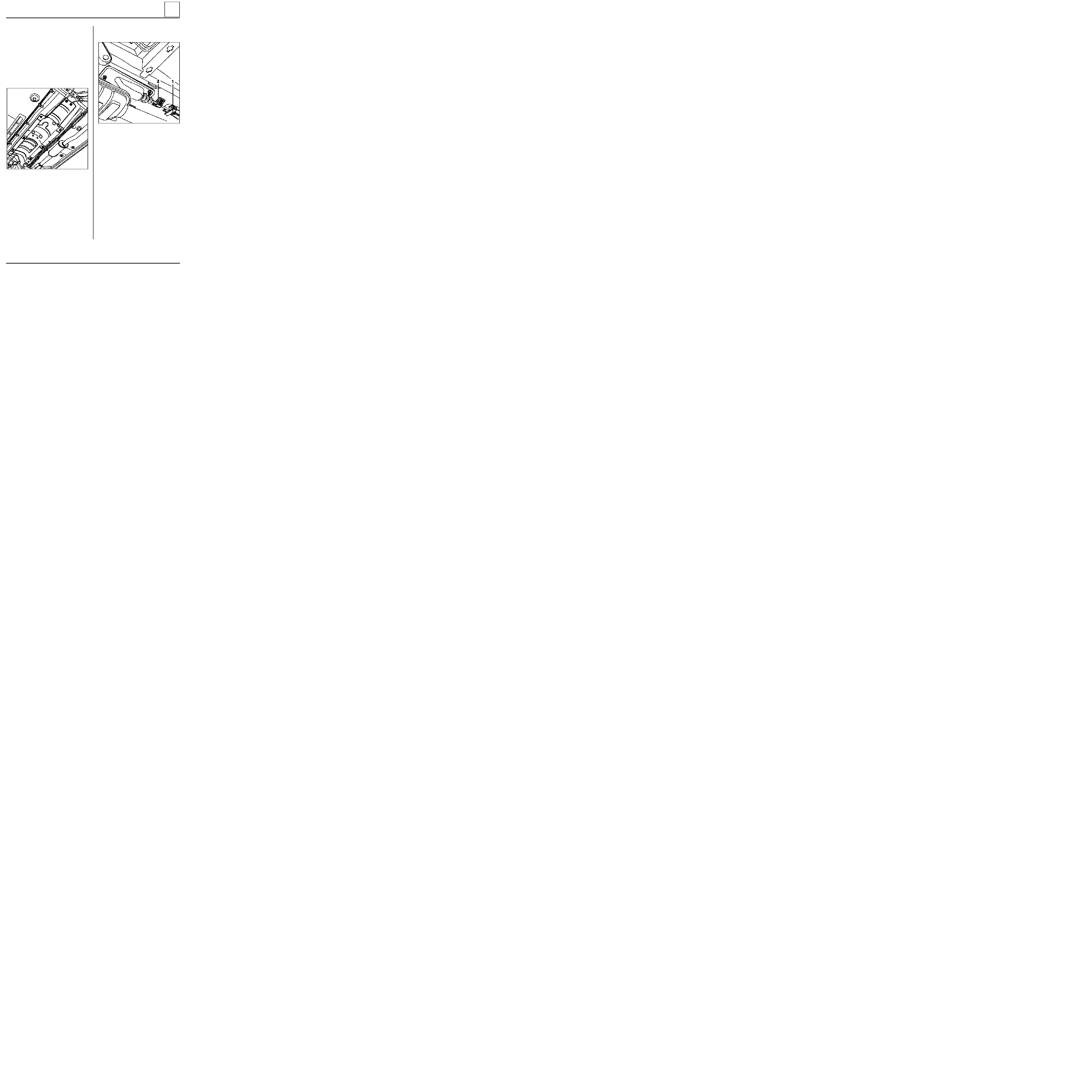
REAR AXLE
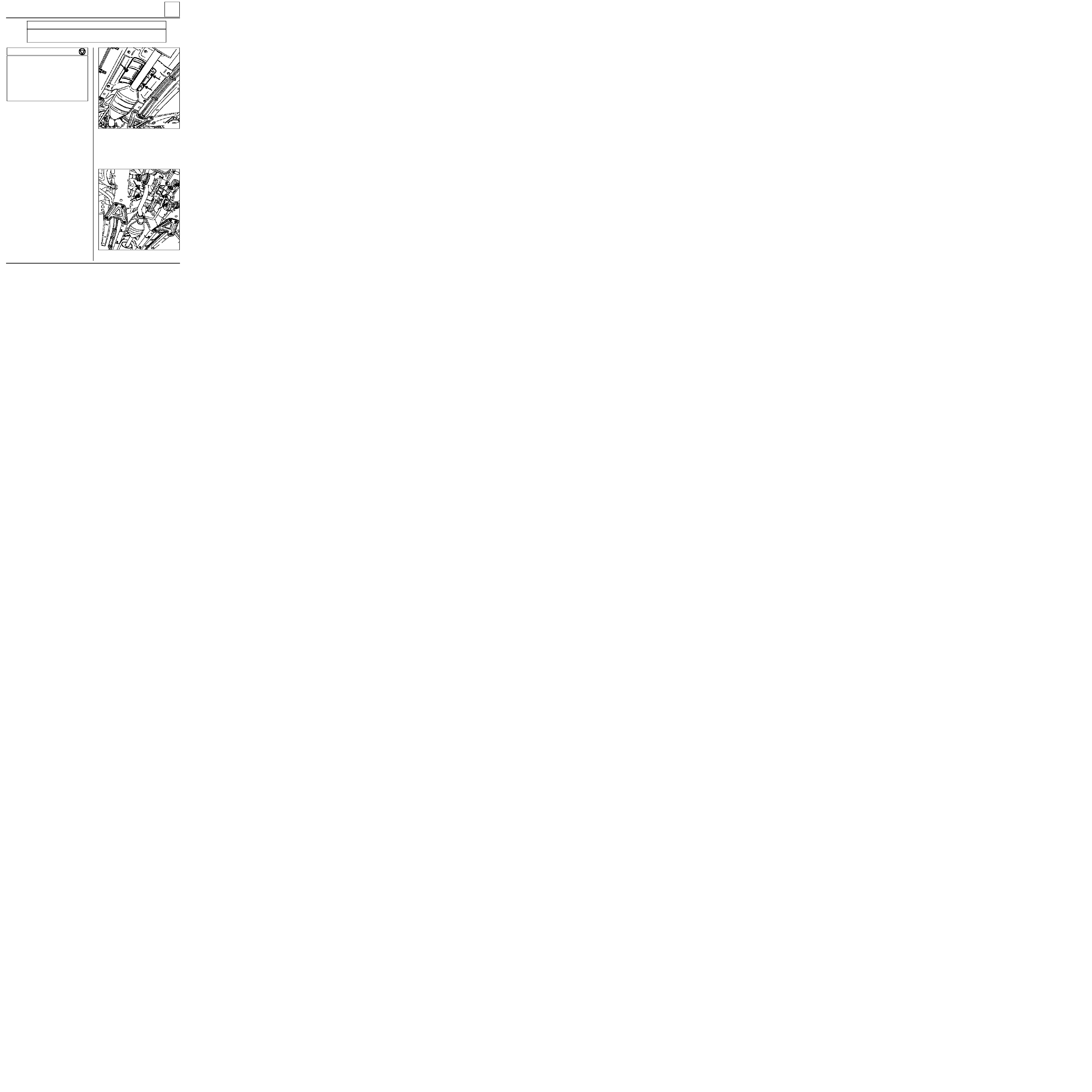
Rear axle assembly
TIGHTENING TORQUES (in daN.m)
Bearing mounting nut
11
Wheel bolt
9
Shock absorber base bolt
8.5
REMOVAL
Put the vehicle on a two post lift.
Fit the pedal press.
Remove:
-
the two lower shock absorber mountings,
-
the brake pipes,
-
the compensator control,
-
the central heat shield,
-
the handbrake cables, disconnecting them
from the central control,
Unclip the cables from the fuel tank.
Support the rear axle assembly and remove the
nuts ( 1 ).
Remove the rear axle assembly.
NOTE : the bolts can be reached under the rear
bench seat (depending on version) after
removing the blanking covers.
REFITTING
Refitting is the reverse of removal.
Bleed the brake circuit.
Adjust the handbrake (see section 37).
Check and if necessary adjust the braking
compensator ( see section 37 ).
33
13132R
33-1
98991
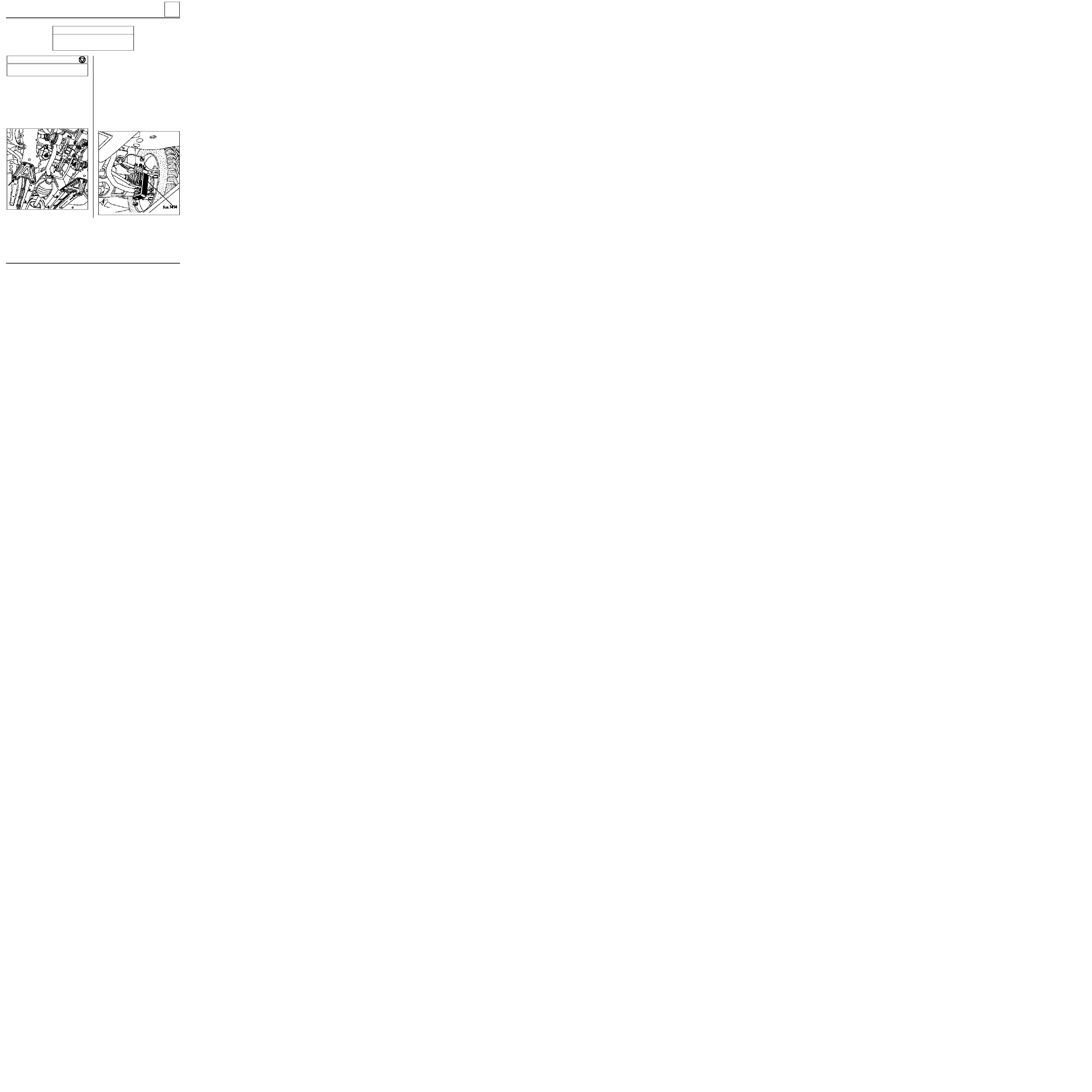
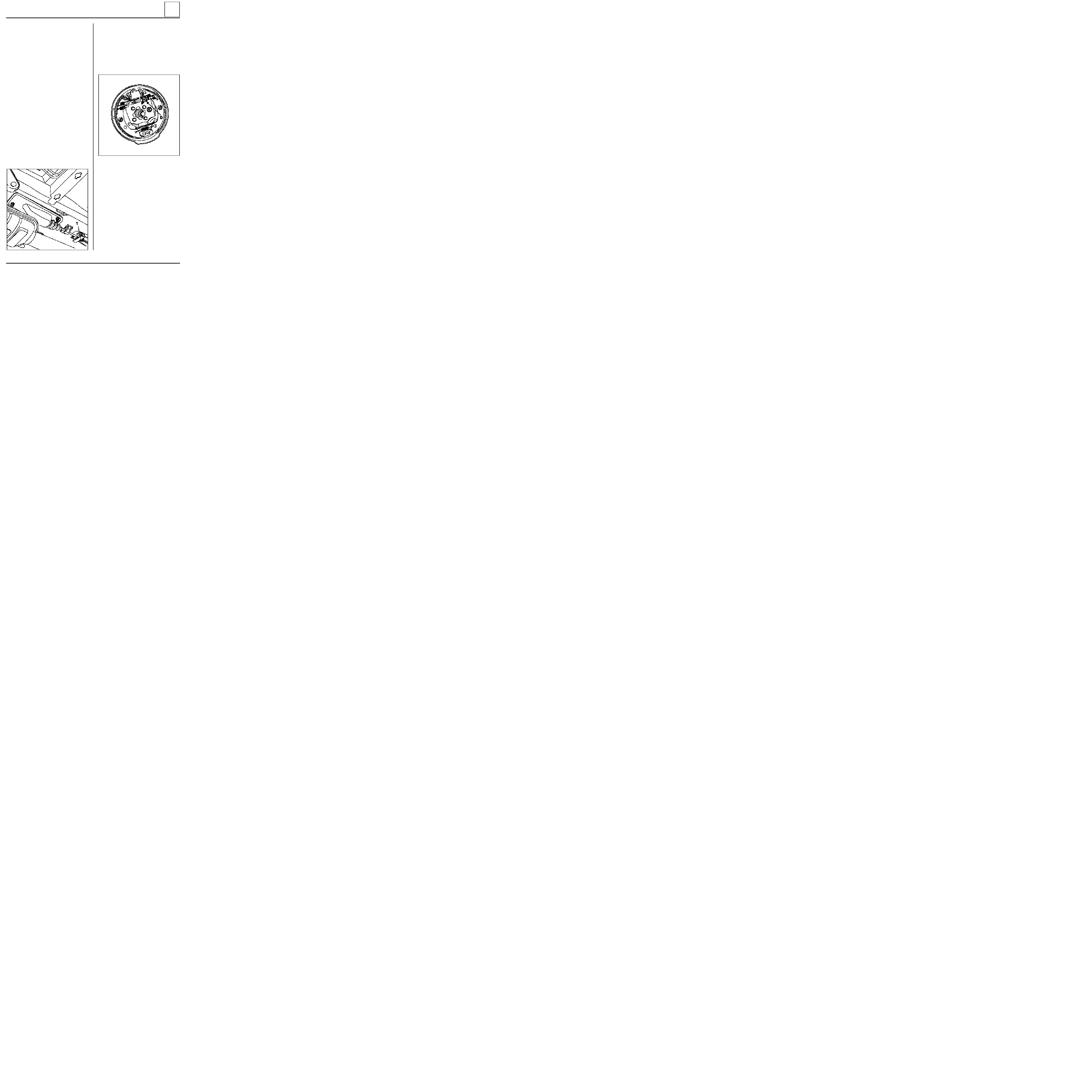
REAR AXLE
Brake drum
Remove
:
-
the nut and stub axle washer,
-
the drum.
The two brake drums must be of the same diameter, if one is reground, the other must also be reground.
Never exceed the diameter marked on the drum.
SPECIAL TOOLING REQUIRED
Emb. 880
Inertia extraction tool
Rou. 943
Hub cover plug extractor
TIGHTENING TORQUES (in daN.m)
Wheel bolts
9
Hub nut
17.5
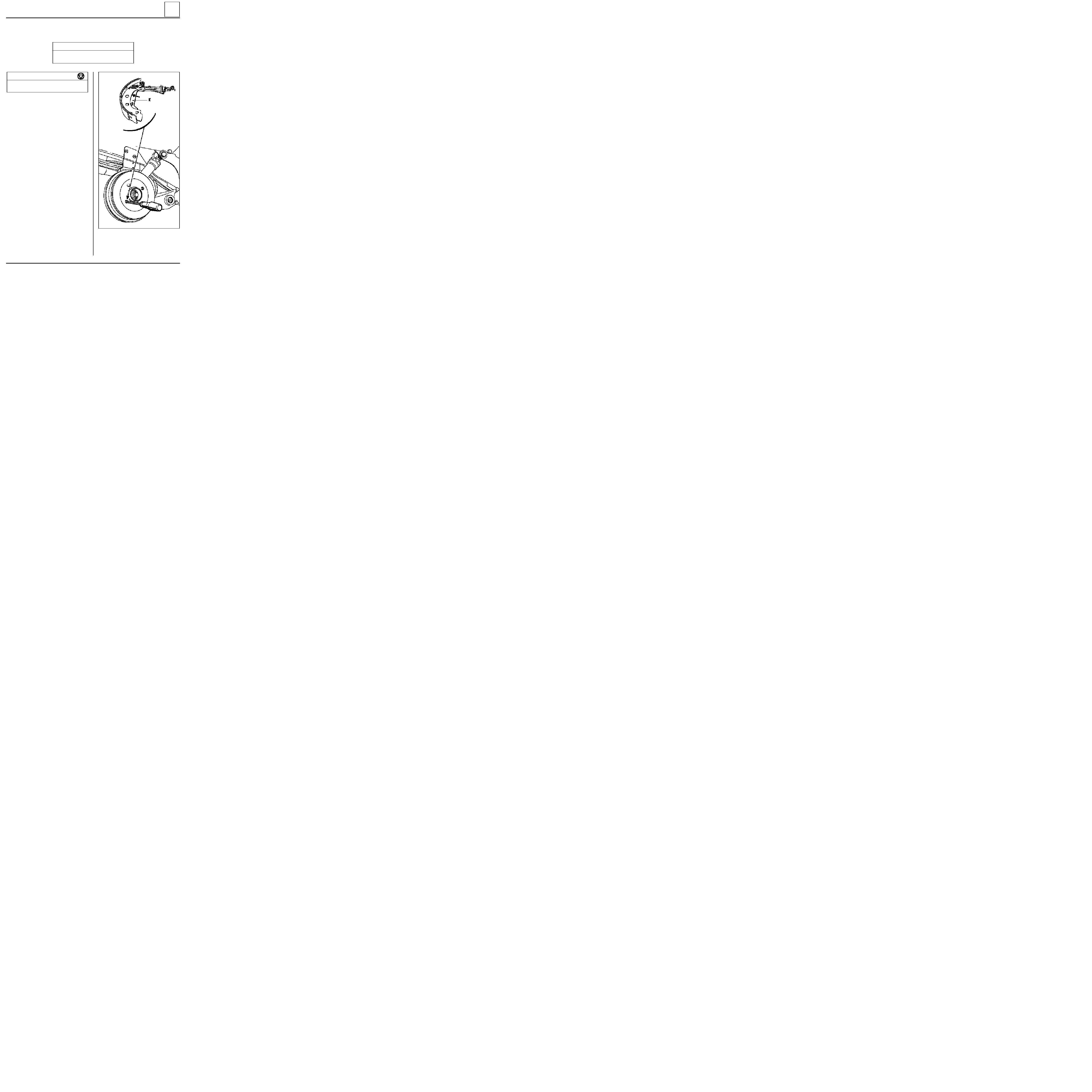
REMOVAL
Remove the hub plug using tools Rou. 943 +
Emb. 880.
Release the handbrake, slacken the secondary
handbrake cables to allow the lever to move back.
Insert a screwdriver through one of the wheel
mounting holes in the drum and push the hand-
brake lever to release the lug from the brake
shoe( E ).
Help the lever to slacken by pushing it towards
the rear.
33
98990G
33-2

REAR AXLE
Brake drum
REFITTING
Remove all dust from the drum and the linings
using brake cleaner.
Fit
:
-
the drum,
-
the washer and the nut, which must be torque
tightened,
-
the plug.
Adjust
:
-
the linings by repeatedly pressing the brake
pedal,
-
the handbrake (see section 37 "Controls").
33
33-3

REAR AXLE
Brake cylinder
REFITTING
Remove all dust from the drums and the linings
using brake cleaner.
Refitting is the reverse of removal.
Bleed the braking circuit (see section 38).
Adjust the linings by repeatedly pressing the
brake pedal.
Check the cut-out pressure (see section 37
"Controls"
).
TIGHTENING TORQUES (in daN.m)
Wheel bolts
9
Hub nut
17.5
Bleed screw
0.5 to 0.8
Pipe bolt
1.7
REMOVAL
Remove
:
-
the drum (see corresponding section),
-
the upper return spring (see paragraph
"Brake linings").
Separate the shoes.
Slacken
:
-
the rigid pipe union on the wheel cylinder
using a pipe wrench,
-
the two cylinder mounting bolts on the
backing plate and remove it.
Check the condition of the shoes. If they have
traces of oil on them, renew them.
33
33-4
Emb. 880
Inertia extraction tool
Rou. 943
Hub cover plug extractor
REAR AXLE
Brake linings (drum)
SPECIAL TOOLING REQUIRED
Wheel bolts
9
Hub nut
17.5
33
TIGHTENING TORQUES (in daN.m)
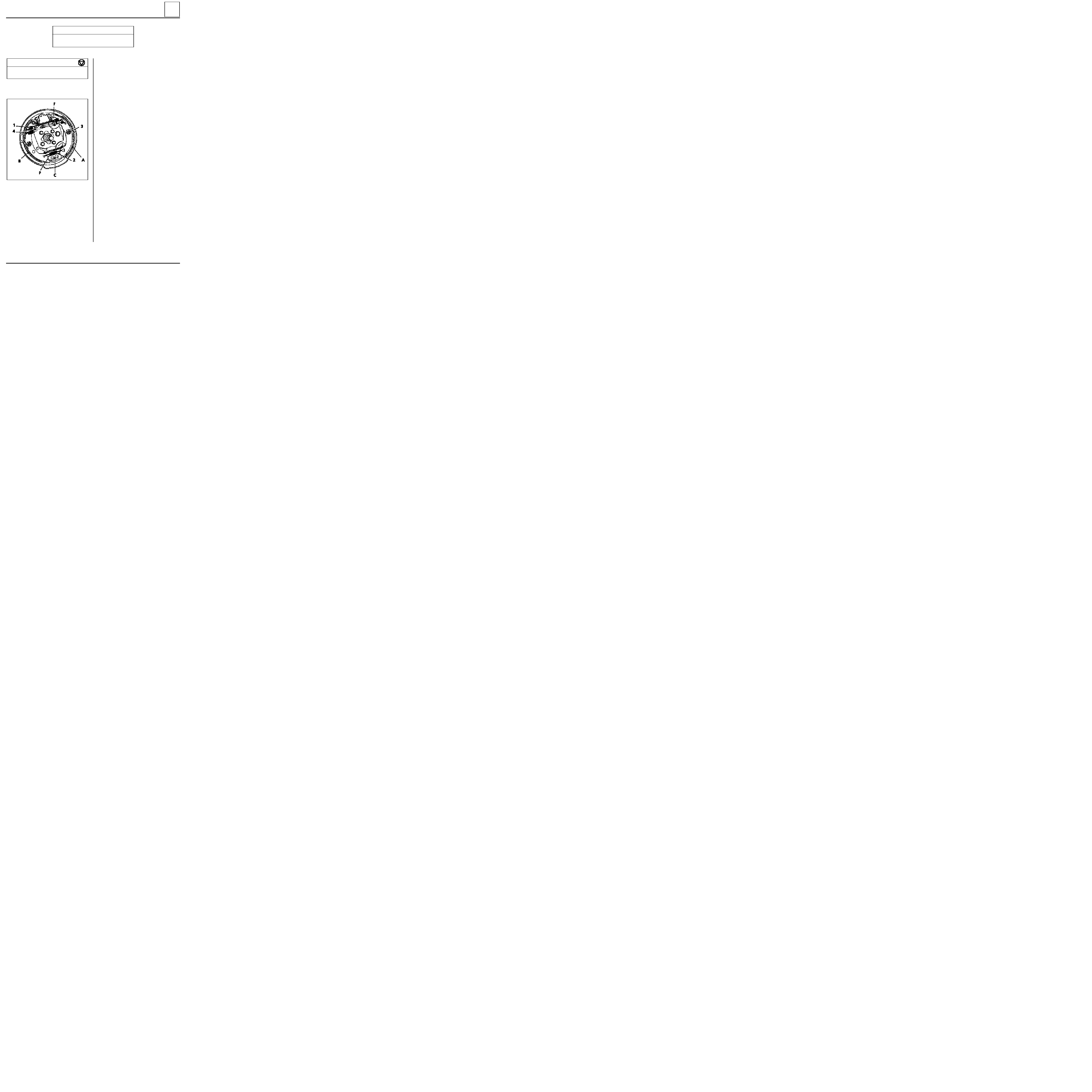
Composition of RAI brake (Rattrapage Auto-
matique Incrémental - automatic wear take up
system).
A
Leading shoe
B
Trailing shoe
C
Fixed point
P
Base of brake shoe
F
RAI wear take up system
1
Upper return spring
2
Lower return spring (for base)
3
Side retainer
4
Handbrake lever return spring
REMOVAL
Brake shoes must be replaced on the complete
axle - never fit shoes of differing makes or
grades.
Remove
:
- the brake drum (see corresponding paragraph),
- the lower spring (2) using brake shoe pliers.
Using adjustable pliers, remove the shoe side
retaining springs.
In turn, pass each brake shoe base over the fixed
point. Squeeze the bases of the shoes together to
separate the ends at the wheel cylinder end.
Separate the assembly (RAI and shoes) from the
brake backing plate then remove it, after
unclipping the handbrake cable.
98992-2R
33-5
REAR AXLE
Brake linings (drum)
33
REFITTING
Present the assembly to the vehicle.
Attach the handbrake cable to the lever.
Squeeze the bases of the shoes together and
position the other ends on the wheel cylinder
pistons. Take care not to damage the covers.
Position the shoes on the fixed point (C).
Fit the side retainers (3).
Remove the pliers from the wheel cylinder pistons
then refit the lower spring (2).
A D J U S T M E N T
Using a screwdriver, adjust the brake shoe
diameter using the notched segment.
Refit the drums without tightening the nuts.
Centre the linings by repeatedly pressing the
brake pedal (approximately 20 times).
Ensure the RAI is operating correctly
(characteristic click from the drums).
Remove the drums.
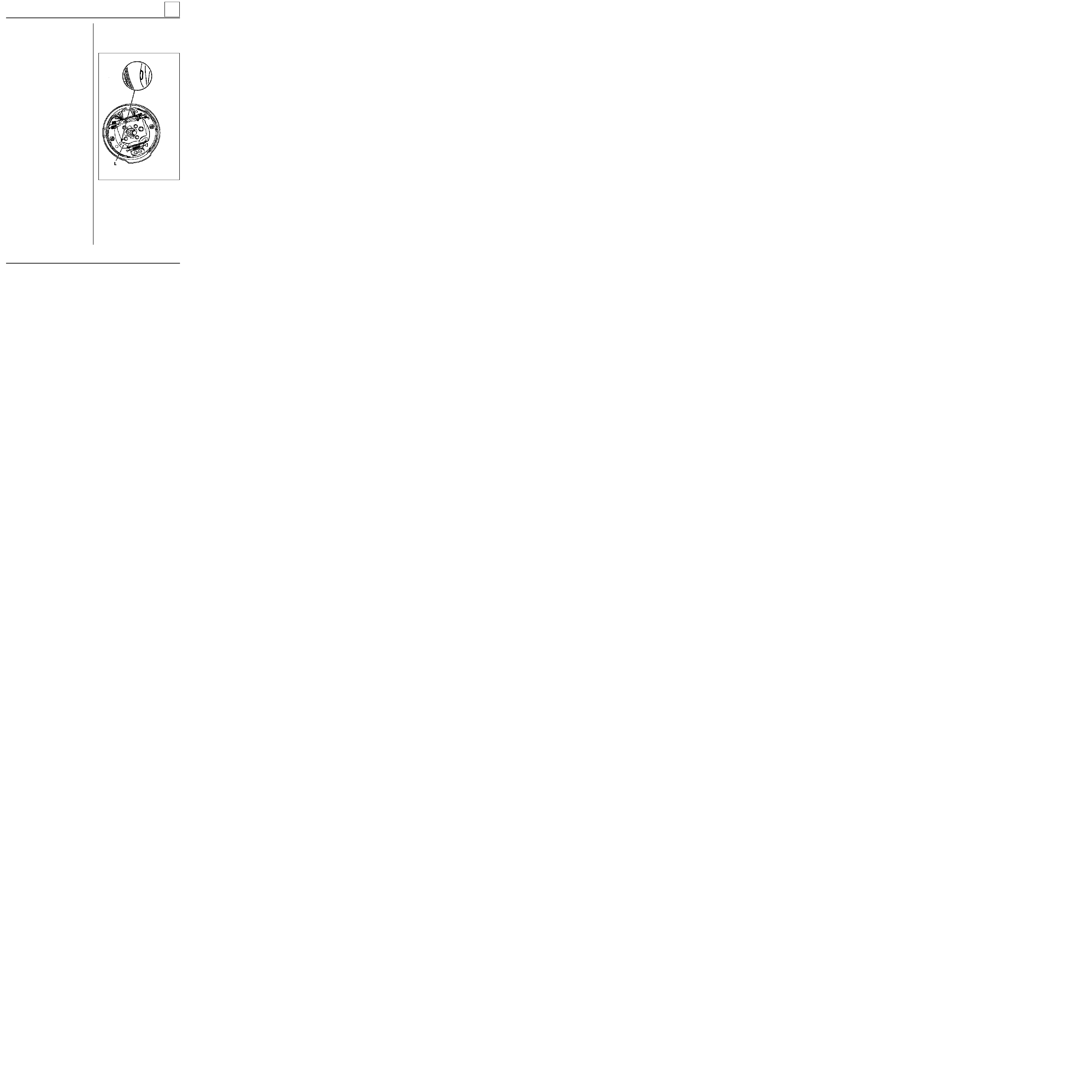
Ensure
:
- the cables slide freely,
- the handbrake levers (L) are correctly
positioned against the shoes.
Progressively tighten the cables at the central
adjustor so that levers (L) start to move between
the 1st and 2nd notch
of the control lever travel
and remain applied from the 2nd notch.
Lock the lock nut on the central adjuster.
Refit
:
- the drums and tighten the nuts to a torque of
17.5 daN.m
,
- the plugs.
98992-3R
33-6

REAR AXLE
Bearing
SPECIAL TOOLING REQUIRED
Emb.
880
Inertia extraction tool
Rou. 943
Hub plug extractor
TIGHTENING TORQUES (in daN.m)
CHECKING
Check the end float using a dial gauge mounted
on the drum : 0 to 0.03 mm maximum.
REMOVAL
Remove
:
-
the hub plug using tools Rou. 943 + Emb. 880,
-
the brake drum (see corresponding
paragraph).
From the drum, remove
:
-
the bearing retaining clip,
-
the bearing using a tube.
Hub nut
17.5
Wheel bolts
9
33
REFITTING
Using a tube and a press, fit the bearing until it
touches the shoulder.
Fit
:
-
a new clip,
-
the drum on the pre-lubricated stub axle,
-
a new lock nut and tighten to the correct
torque,
-
the hub plug.
Adjust
:
-
the brake shoes by repeatedly pressing the
brake pedal,
-
the handbrake (see section 37 "Controls").
33-7

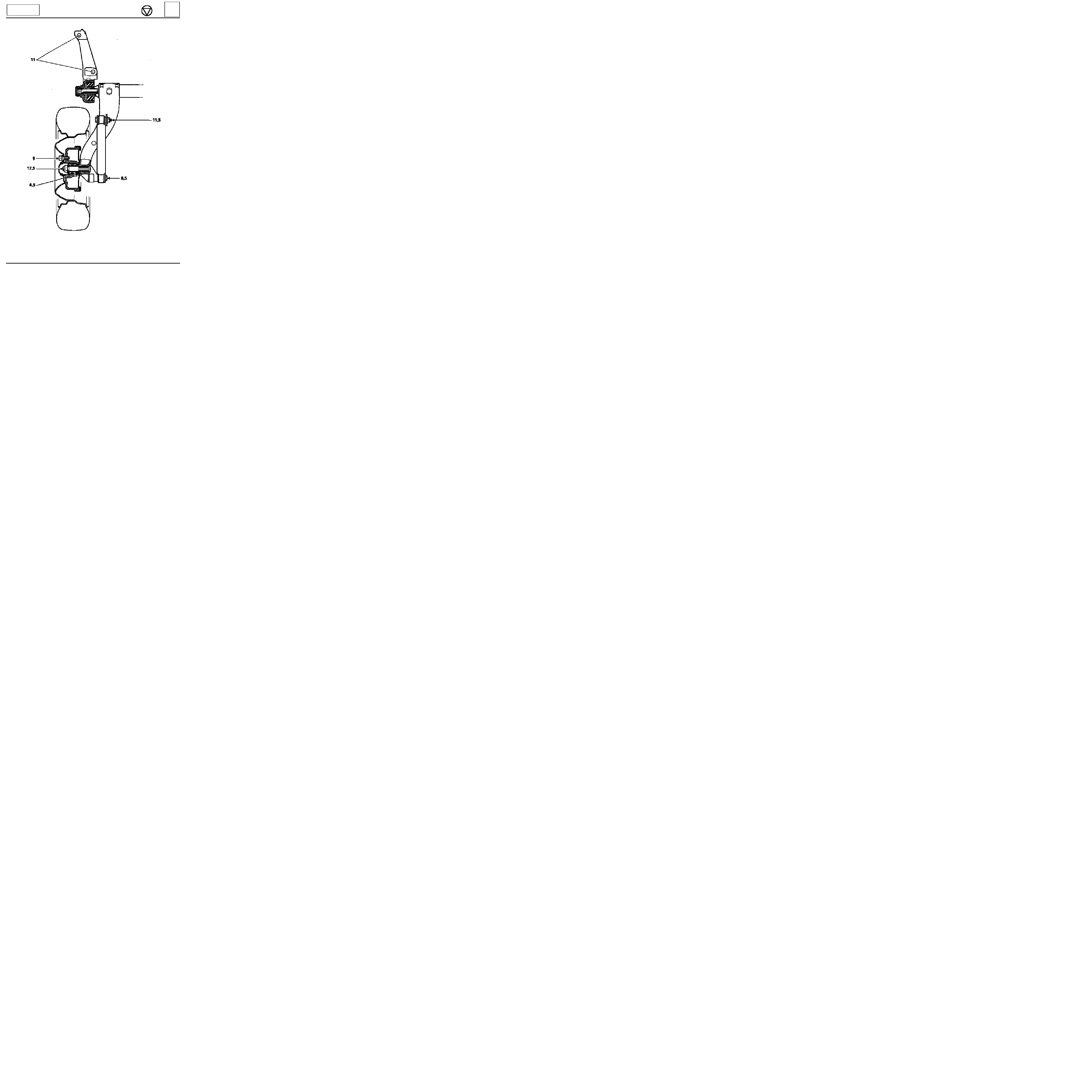
REAR AXLE
Shock absorber
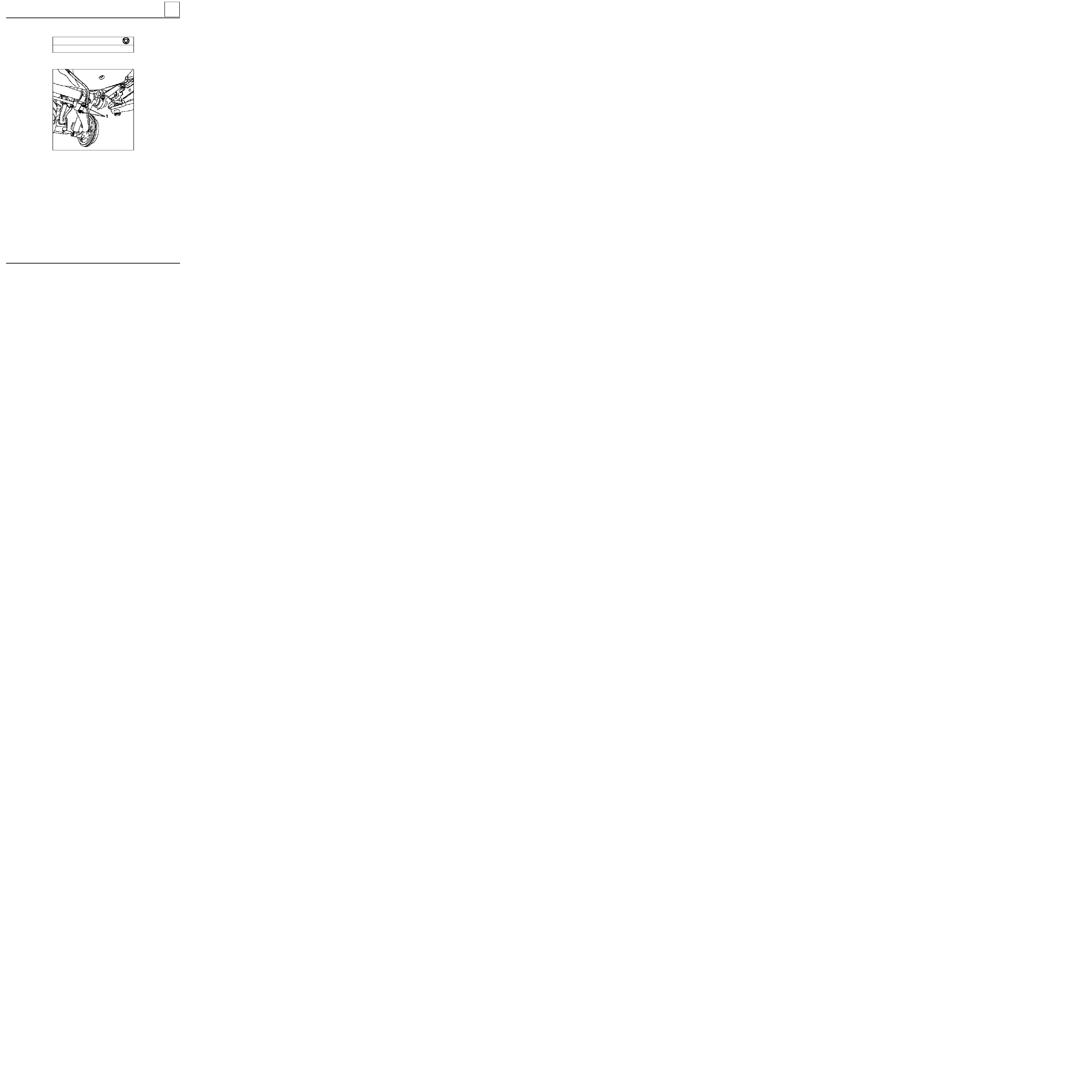
REMOVAL
With the vehicle on its wheels, remove the lower
mounting bolt (1).
Lift the vehicle and remove
:
-
the wheel,
-
the upper mounting bolt (2),
-
the shock absorber.
PRECAUTIONS TO BE TAKEN BEFORE FITTING
Shock absorbers are stored horizontally in the
Parts Stores.
Under these conditions it is possible that the shock
absorbers, which are designed to operate in a ver-
tical direction, will have de-primed.
Before fitting the shock absorbers to the vehicle
compress them a few times by hand in the vertical
position.
REFITTING
Fit
:
-
the shock absorber,
-
the upper mounting bolt coated with
MOLYKOTE BR2
, without tightening it,
-
the wheel.
Lower the vehicle.
Position the lower mounting bolt coated with
MOLYKOTE BR2.
Torque tighten both bolts.
33
Upper mounting bolt
11.5
Lower mounting bolt
8.5
TIGHTENING TORQUES (in daN.m)
13133R
33-8
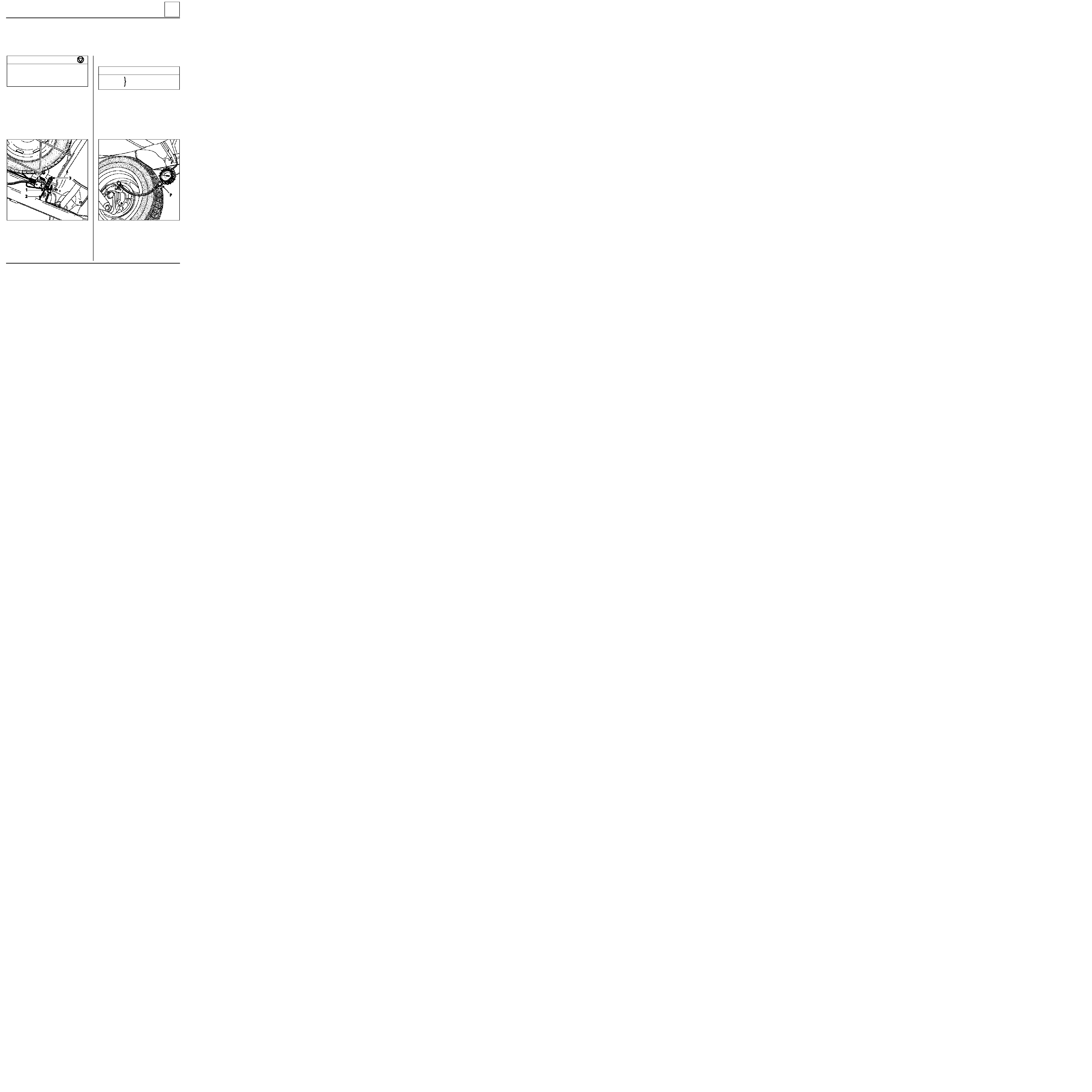
REAR AXLE
Anti-roll bar, tubular rear axle
TIGHTENING TORQUES (in daN.m)
Bar mounting bolt
5.5
REMOVAL
1
Mounting bolt
Put the vehicle on a lift with the wheels hanging
free.
On each side, remove bolts (1) and retain the
captive nuts.
Remove the bar.
REFITTING
On each side, refit the bolts (1) with the captive
nuts.
Tighten to the recommended torque.
33
13132R
33-9

REAR AXLE
Half suspension arms, tubular rear axle
REFITTING
Ensure the bearing races or the needle bearings
are in perfect condition, otherwise replace them
(see section "Bushes, tubular rear axle").
The needle bearings are greased for life and do
not require further lubrication.
NOTE :
new suspension arms are supplied by the
Parts Department fitted with bearing races or
needle bearings (depending on side).
Fit the two half suspension arms together until
dimension (B) is obtained.
NOTE :
dimension (B) corresponds to the distance
between the same two mounting points for the
anti-roll bar on the suspension arms. It is therefore
possible to obtain this dimension by positioning
the anti-roll bar in its location and checking the
mounting bolts can be correctly positioned.
Ensure the fitting direction is observed.
Refitting is then the reverse of removal.
NOTE :
if the half suspension arm is renewed,
bond the brake backing plate mounting bolts
with
Loctite FRENBLOC.
Bleed the brake circuit.
Adjust the handbrake control (see section 37).
33
TIGHTENING TORQUES (in daN.m)
Bearing mounting nut
11
Anti-roll bar mounting bolt
5.5
Wheel bolt
9
Shock absorber base bolt
8.5
REMOVAL
Put the vehicle on a two post lift, remove:
-
the anti-roll bar,
-
the lower shock absorber mounting,
-
the secondary handbrake cable, disconnecting
at the central adjuster under the vehicle,
-
the brake pipe,
-
the two bearing mounting nuts (A).
Slacken the two nuts (A) on the other bearing so
the half suspension arm can be released from its
mountings.
Remove the half suspension arm, separating one
from the other.
13132R1
86320R
33-10
Grind the bearing races on the male suspension
arm (right hand side) using a straight grinding
wheel, taking care not to mark the tube.
REAR AXLE
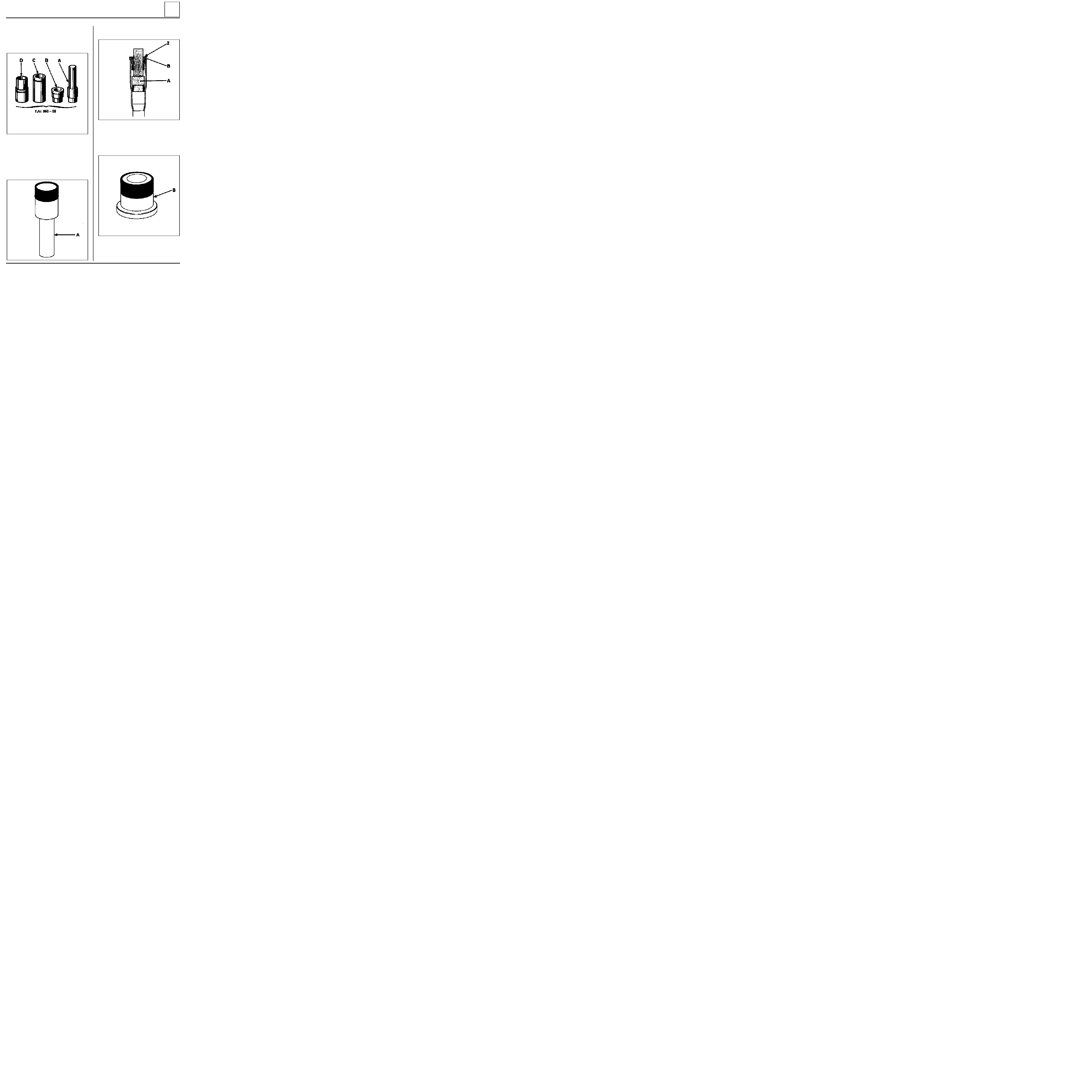
Bushes, tubular rear axle
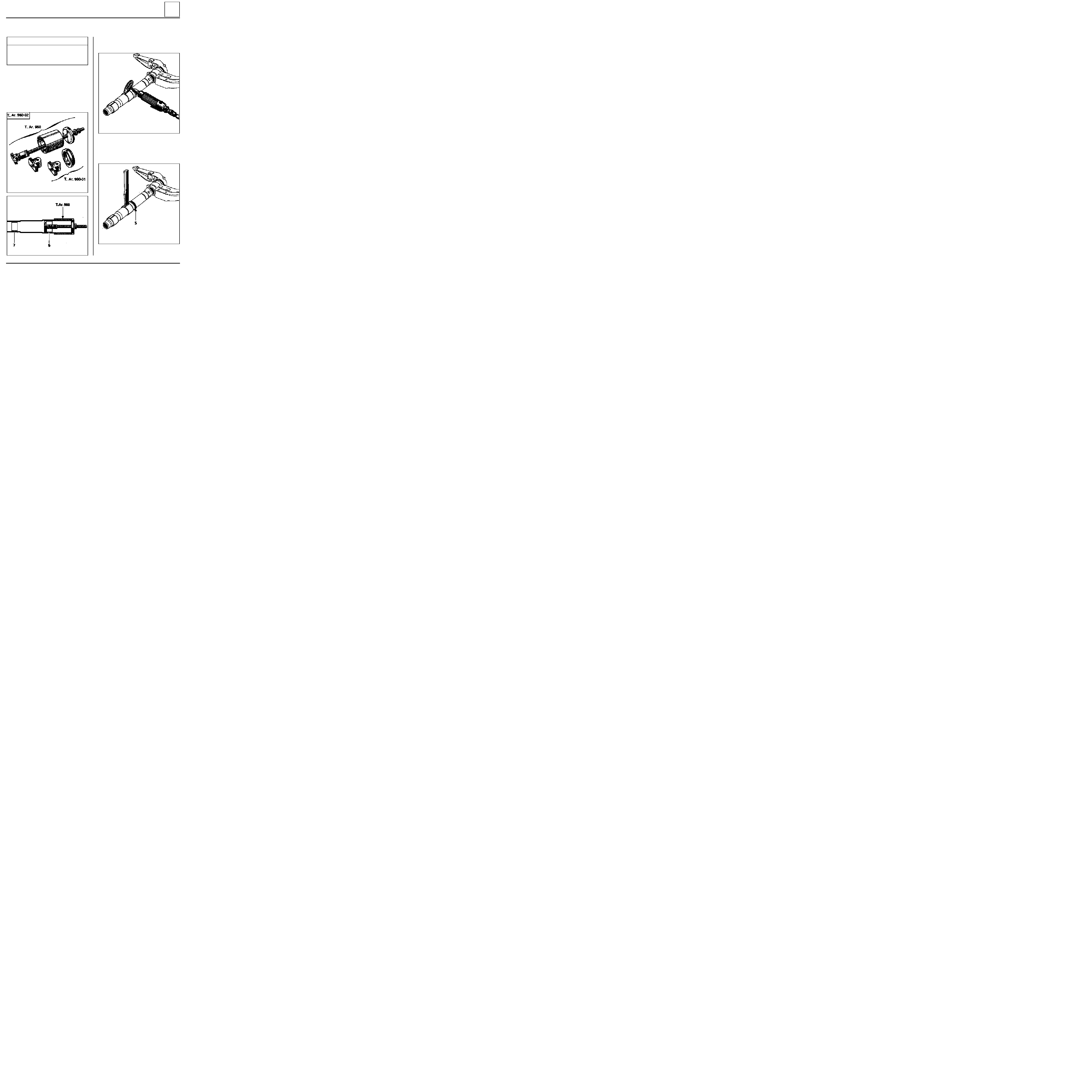
SPECIAL TOOLING REQUIRED
T. Ar. 960-02
Bush + spacer extractor
T. Ar. 960-05
Tooling for replacing needle
bearings.
REMOVAL
Remove from the female suspension arm (left
hand side) :
-
the outer bush (6) using tool T.Ar. 960,
-
the inner bush (7) using the small socket of
tool T.Ar. 960.
This operation is carried out after removing the complete rear axle assembly and separating the two
suspension arms.
33
Split the bearing races using a chisel then remove
them.
Cut and remove the seal (5).
86182R
86180R
90864S
90863R
33-11
REAR AXLE
Bushes, tubular rear axle
REFITTING
Tool T.Ar. 960-05 must be used for fitting the
needle bearings and the bearing races.
Fit :
-
the small needle bearing on the mandrel (A),
-
the mandrel (A) into the tube, using mandrel
(B) as a guide.
33
On the press, press on mandrel (A) until it touches
face (2) of mandrel (B)
.
Fit:
-
the large needle bearing on mandrel (B),
90874R
90866R
90865R
90868R
33-12

REAR AXLE
Bushes, tubular rear axle
-
mandrel (B) in the tube, using mandrel (A) as a
guide.
33
On the press, press on until mandrel (B) touches
the tube.
Remove mandrels (B) and (A).
Fit the new seal (5) on the male tube.
The bearing races have an input chamfer on one
side.
It is important to observe the fitting direction:
chamfer (4) must be aligned as shown in the
diagram to ensure sufficient bearing surface to
press the parts on.
Fit:
-
the large bearing race in sleeve (D),
-
the assembly of sleeve (D) and (C) on the
tube.
90868-1R
90941R
90868-2R
90867-5R
33-13

REAR AXLE
Bushes, tubular rear axle
Press on the assembly (D) and (C) until the sleeve
(C) reaches the edge (3) of the tube.
Fit :
-
the small bearing race in sleeve (C),
-
sleeve (C) on the tube, using sleeve (D) as a
guide.
On the press, press on until the sleeve (C) reaches
the edge (3) of the tube.
Remove sleeves (C) and (D).
I M P O R T A N T
When pressing on the parts, if the weight has
been taken on the axle mounting bearings, it
must be ensured that the suspension arms are
correctly located in their mountings (risk that
they may have been moved)
.
Recentre them if necessary.
Assemble the two half axle sections.
NOTE : the needle bearings are greased for life
and do not require further lubrication.
Reconnect and refit the rear axle assembly to the
vehicle (see corresponding section).
33
90867-2R
90867-4R
90867-3R
33-14
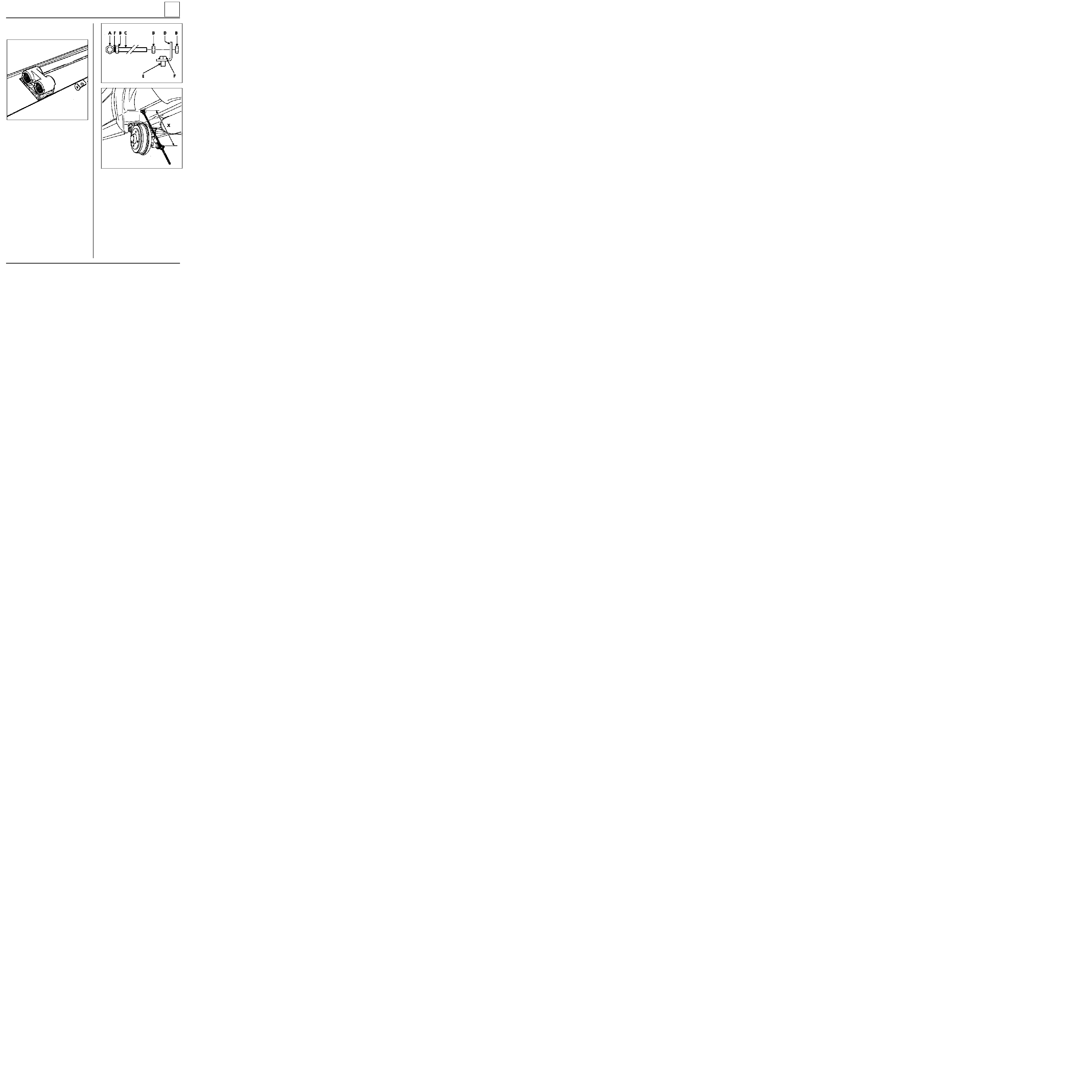
REAR AXLE
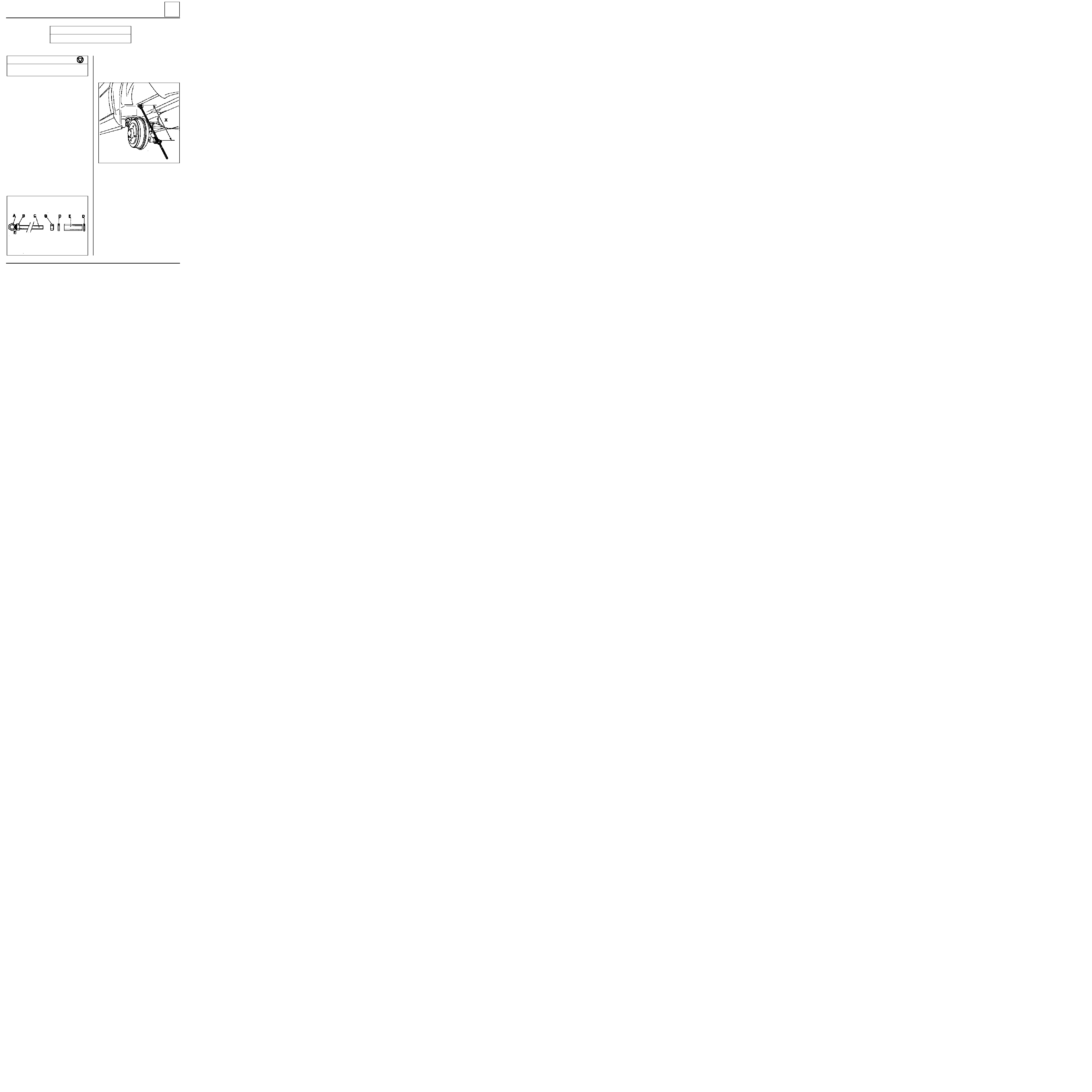
Suspension bars, tubular rear axle
SPECIAL TOOLING REQUIRED
Emb. 880
Inertia extractor
TIGHTENING TORQUES (in daN.m)
Upper shock absorber mounting bolt
11.5
Lower shock absorber mounting bolt
8.5
REMOVAL
With the vehicle raised so its wheels hang free, re-
move the shock absorber on the side in question.
Remove the bar from the side, using tool
Emb. 880.
REFITTING
In order to position the suspension arm so that the
bar may be correctly positioned, a tool must be
locally made.
A
Nut, diameter 14 mm
B
Nut, diameter 12 mm
C
Threaded rod, diameter 12 mm - length 660
mm
D
Bracket from flat sheet 30 x 5 mm
E
12 x 60 mm
bolt, cut to a length of 20 mm
F
Weld
33
75505R
Preset the tool to obtain dimension "X".
X = 402 mm
Fit the tool in place of the shock absorber.
88637R2
Coat the splines of the bar with
MOLYKOTE BR2
,
fit it into the bearing and the suspension arm, and
try, by rotating the rod, to find the position where
it fits freely into the splines of the suspension arm
and the bearing.
Remove the tool and refit the shock absorber.
Return the vehicle to its wheels and measure the
underbody heights (see section "Underbody
heights - Tubular rear axle").
Check and adjust if necessary:
-
the braking compensator,
-
the headlights.
33-15
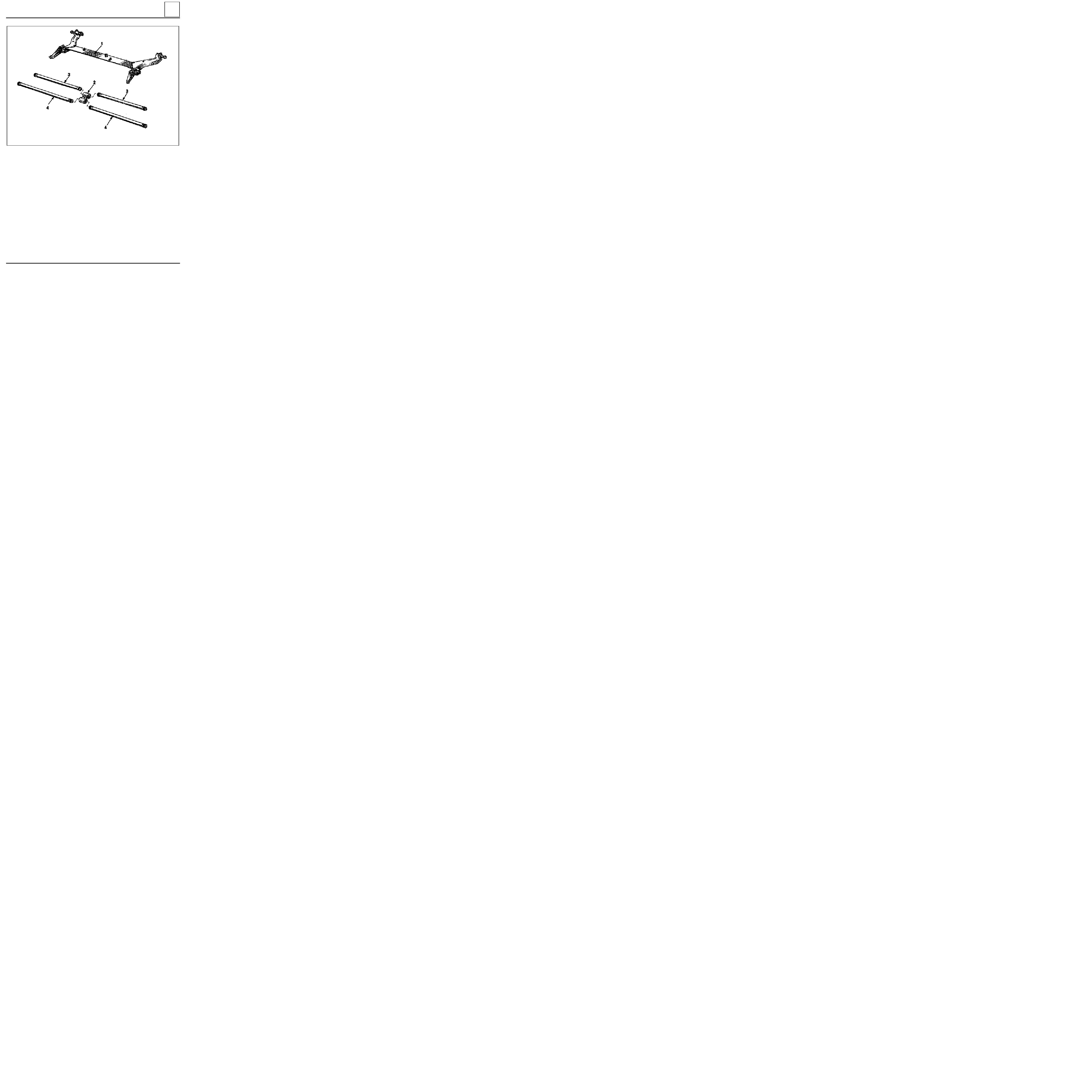
REAR AXLE
Four bar rear axle
The four bar rear axle comprises:
-
two arms connected by an "L" section. This assembly (1) cannot be dismantled. Any deformation would
mean its complete replacement.
-
two anti-roll bars (3),
-
two suspension bars (4),
-
a shackle (2) connecting the bars.
The assembly is connected to the body by two bearings mounted on rubber bushes.
NOTE : Never take the weight of the vehicle using a jack on the "L" section (1) to lift the vehicle.
33
PRN3300
33-16
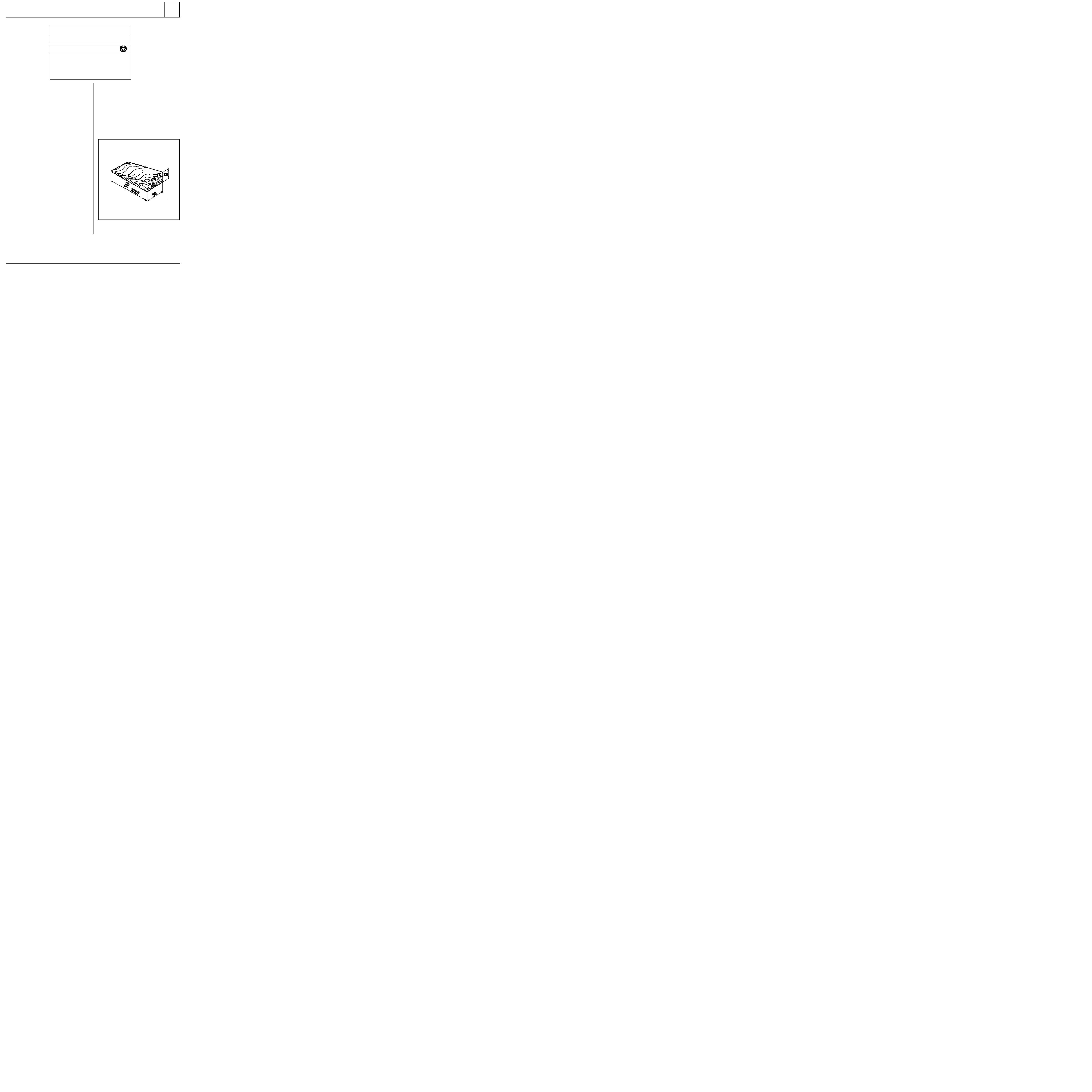
REAR AXLE
Four bar rear axle
SPECIAL TOOLING REQUIRED
Emb. 880
Inertia extractor
TIGHTENING TORQUES (in daN.m)
Upper shock absorber mounting
8.5
Lower shock absorber mounting
11.5
Wheel bolts
9
REMOVAL
Remove:
-
the wheels,
-
the shock absorbers,
-
the suspension bar plugs.
Remove using tool Emb. 880 :
-
the two suspension bars,
-
the two anti-roll bars, retaining the central
shackle.
Clean and lubricate the bar splines using
MOLYKOTE BR2
.
REFITTING
The anti-roll bars cannot be removed from the
vehicle when the shock absorber replacement tool
is in position. Because of this, and to make it
easier to refit the shackle, a wooden block must
be made according to the diagram below.
Fit:
-
the shackle on the block (locally made) in the
centre of the rear axle assembly,
33
13135R
Dimensions in mm and degrees (
°
).
33-17
REAR AXLE
Four bar rear axle
-
the first anti-roll bar, ensuring the angle of
the block is observed, and the bar is inserted
freely.
33
13134S
-
the second anti-roll bar, ensuring it engages
freely.
In order to position the suspension arm so that the
bar may be correctly positioned, a tool must be lo-
cally made.
A
Nut, diameter 14 mm
B
Nut, diameter 12 mm
C
Threaded rod, diameter 12 mm - length 660
mm
D
Bracket from flat sheet 30 x 5 mm
E
12 x 60 mm
bolt, cut to a length of 20 mm
F
Weld
75505-1R1
88637R2
Preset the tool to obtain dimension "X".
X = 430 mm
Fit the tool in place of the shock absorber.
Refit
:
-
the bar plugs,
-
the shock absorbers,
-
the wheels.
Put the vehicle on its wheels and measure the un-
derbody heights ( see section "values and set-
tings"
).
33-18

REAR AXLE
Four bar rear axle
33
Check and if necessary adjust:
-
the braking compensator,
-
the headlights.
REMINDER
When adjusting for a wheel height difference
between the right and left hand sides, always
make the adjustment on the anti-roll bars.
The adjustment for a difference in dimension " X"
between the right and left hand sides should
always be made on the suspension bars.
33-19
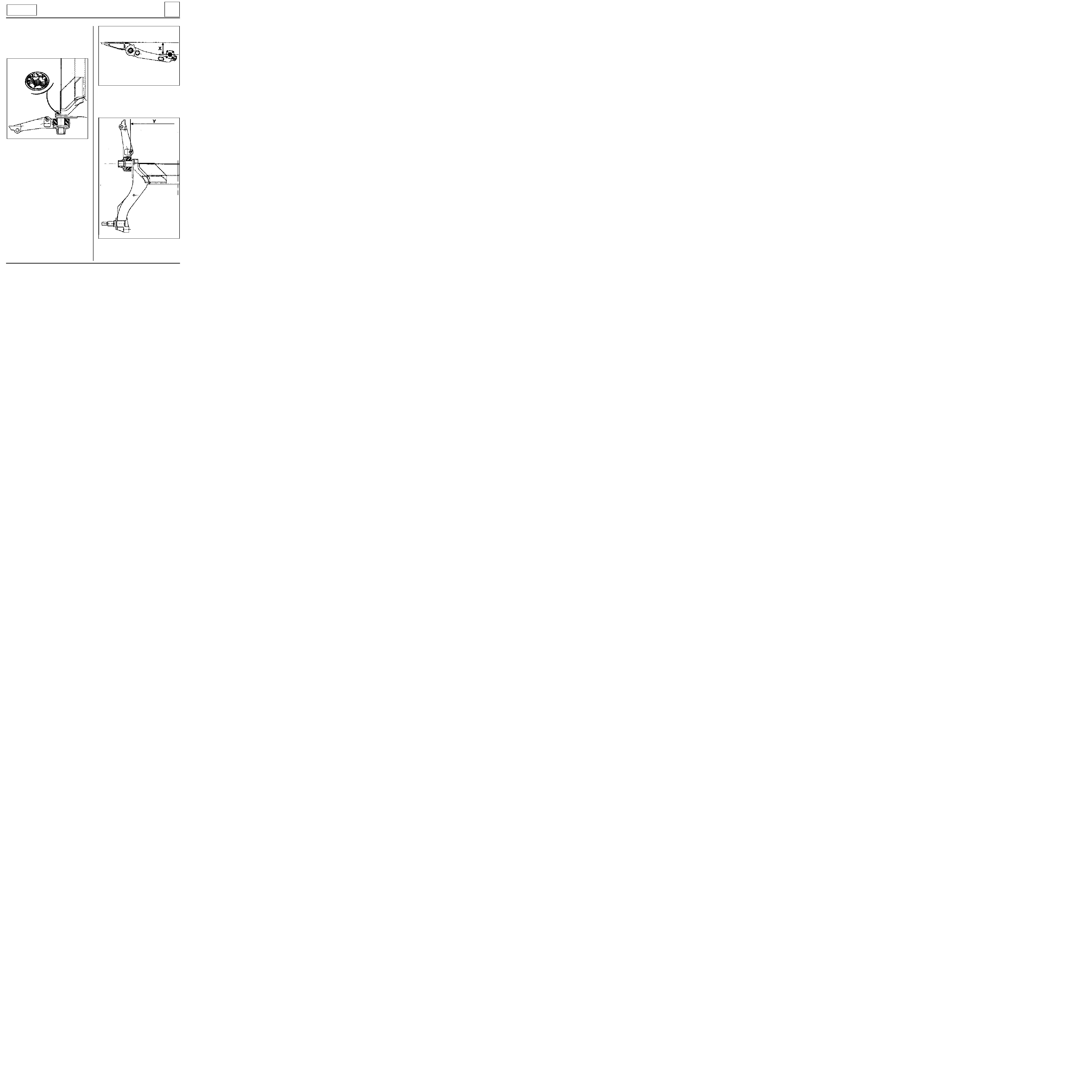
REAR AXLE
Suspension arm bearings
This operation is carried out after removing the
rear arms and the suspension bars.
REMOVAL
Totally immerse the bearing in brake fluid to
soften the rubber bush.
Using a two or three claw extractor, remove the
external part of the bearing by tearing off the
rubber.
Saw through the inner ring taking care not to
scratch in the tube of the arm.
REFITTING
The bearing is fitted in the arm on the press,
ensuring the correct alignment is observed and
the clearance between the bearing and the arm is
correct.
Alignment
Observe dimension "X" between the bearing
pressure face and the stub axle shaft:
X = 156 mm
±
3.5
TUBULAR REAR
AXLE
33
DI3303
85909S
75362S
DI3310
33-20
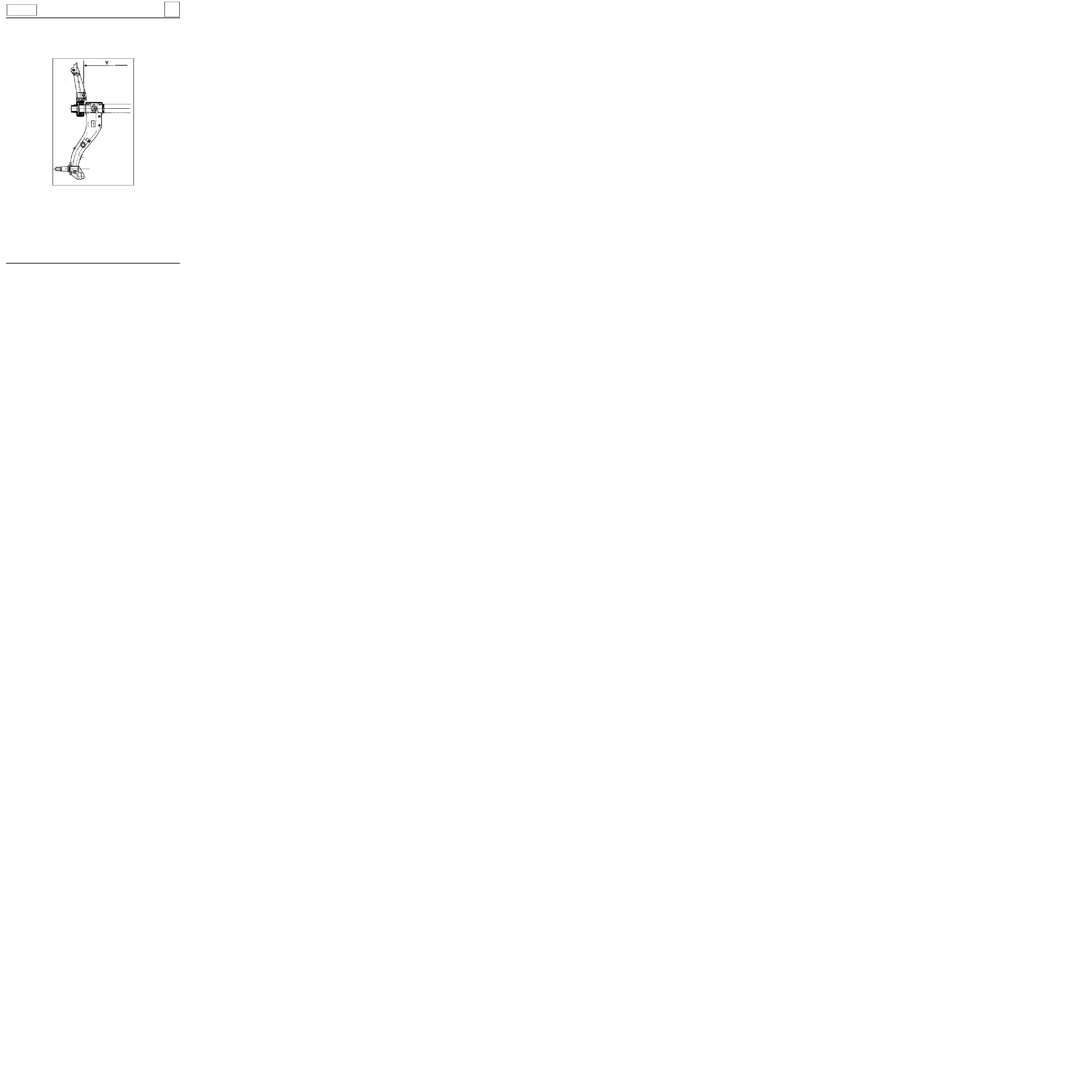
REAR AXLE
Suspension arm bearings
Clearance
In this position, press on the bearing until the
dimension between the bearing centres is :
Y = 1164 mm
±
1
Fit the arm to the vehicle.
TUBULAR REAR
AXLE
33
DI3311
33-21
REAR AXLE
Suspension arm bearings
This operation is carried out after removing the
rear axle assembly and the suspension bars.
REMOVAL
Weld a spacer (example : nut) in the central tube
of the bush.
Remove the bush - bearing assembly on the press.
REFITTING
The bearing is fitted in the arm, ensuring the cor-
rect alignment is observed and the clearance bet-
ween the bearing and the arm is correct.
Alignment
Observe dimension "X" between the bearing
pressure face and the stub axle shaft
X = 124
±
3.5 mm
Clearance
In this position, press on the bearing until the
dimension between the bearing centres is :
Y = 1164
±
1 mm
Fit the rear axle assembly to the vehicle and refit
the suspension bars (see corresponding section).
FOUR BAR REAR
AXLE
33
90241G
DI3312
DI3313
33-22

Offset
(in mm)
DI3501
WHEELS AND TYRES
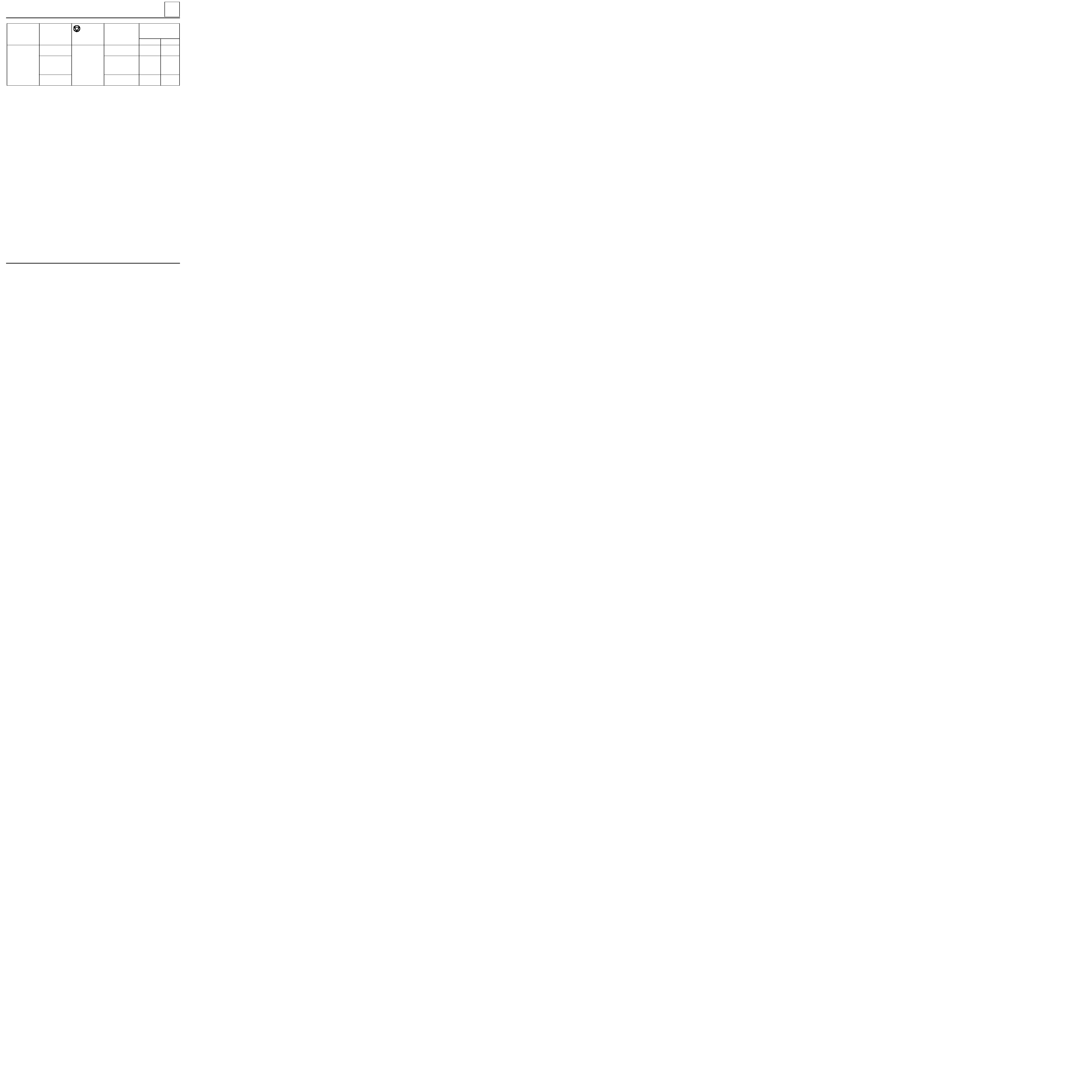
Specifications
WHEEL RIMS
There are two forms of wheel identification marking:
-
engraved markings for steel rims,
-
cast marking for alloy rims.
The marking gives the main dimensional specifications of the wheel.
The marking may be complete:
Example : 5 1/2 J 14 4 CH 36
or simplified
Example : 5 1/2 J 14
35
The four wheel bolts are over a diameter of 100
mm
(4 mounting bolts).
Maximum run-out: 1.2 mm
measured on the rim
edge (at G).
Maximum eccentricity: 0.8 mm
measured on the
pressure face of the tyre beads.
F
E
Number
of holes
D
C
B
WIDTH
(in inches)
5 1/2
A
TYPE
OF WHEEL
5 1/2 J 14
4 CH 36
J
14
4
CH
36
RIM
PROFILE
NOMINAL DIAMETER
(in inches). under tyre
bead
Tyre bead
profile
35-1
85920R2
WHEELS AND TYRES
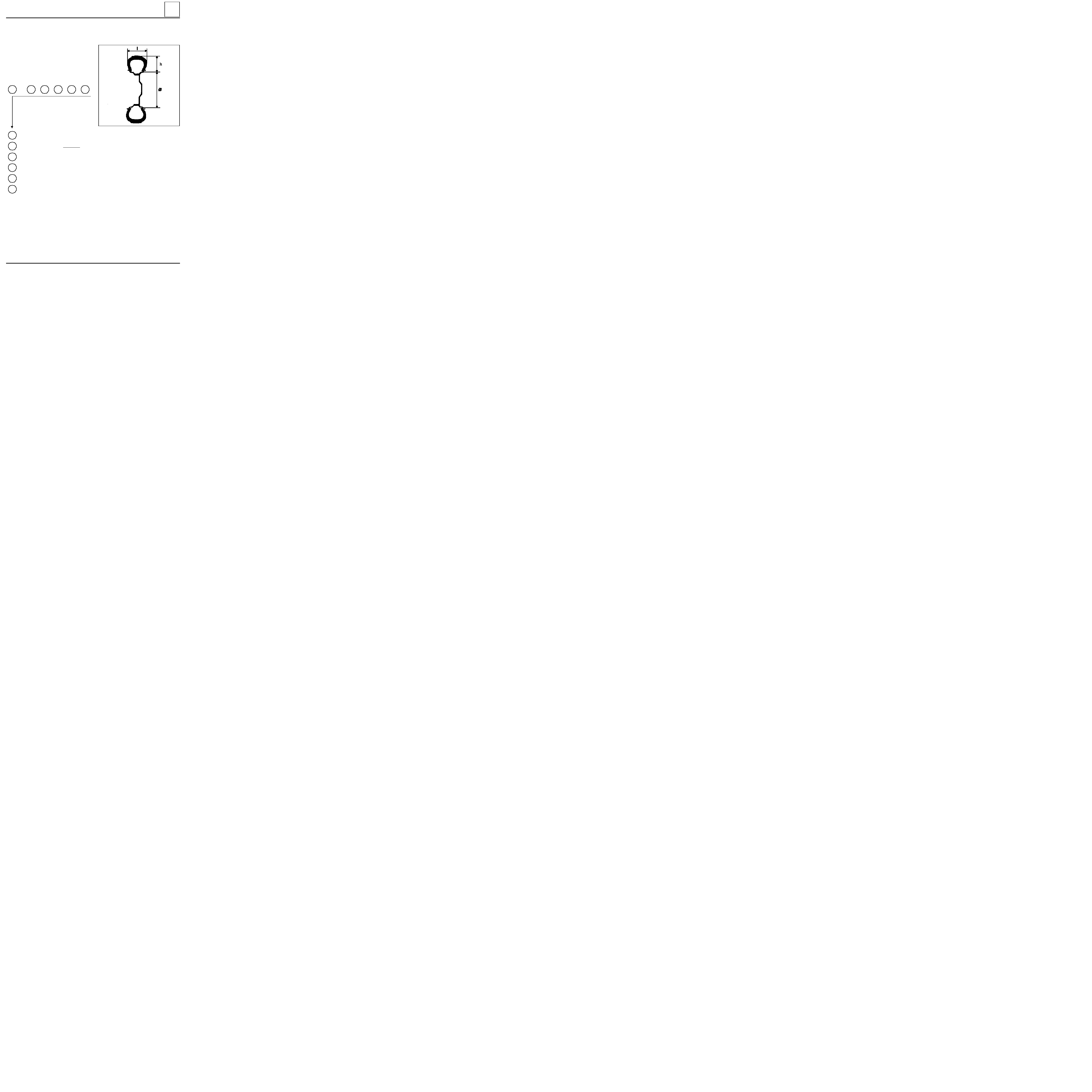
Specifications
Examples of identification marking
165
/
70
S
R
13
83
1
2
5
4
6
3
165/70 R 13 83 S
TYRES
35
1
165
70
2
3
S
R
5
13
4
Tyre width in mm ( l ) section
Ratio h/l
height
width
Speed index 180 km/h maximum
Radial structure
Inner diameter expressed in inches. Corresponds to the diameter of the rim.
83
6
Load index
Some speed symbols :
Maximum speed
km/h
R
170
S
180
T
190
U
200
H
210
V
240
ZR over 240
Types of structure :
Diagonal
No marking
Radial
R
Bias belted
B
35-2
WHEELS AND TYRES
Specifications
The tyre inflation pressures are values for a fully laden vehicle or motorway use.
The tyre inflation pressure must be checked when cold. The increase in temperature during driving increases
the pressure by 0.2 to 0.3 bar.
If the inflation pressures are checked when the tyres are warm, take this pressure increase into consideration.
Never deflate a warm tyre
.
(1) Reinforced tyre.
Chains
For safety reasons, chains may NEVER be fitted to the rear axle.
"Snow" or "thermorubber" tyres: all four wheels must be fitted with these tyres to retain vehicle adhesion as
far as possible.
35
Type
Rim
Wheel bolt
torque
(daN.m)
Tyres
Inflation pressure
(bar) cold
Front
Rear
FC0X
KC0X
5 B 13
5 B 13
5,5 J 14
9
2.8
2.6
2.4
3.6
2.9
3.0
165/70 R 13 C 88/86
165/70 R 13 83 (1)
165/70 R 14
35-3

88659R
WHEELS AND TYRES
Wheel balancing
35
BALANCE WEIGHTS
Only use weights provided by the Parts
Department:
-
fitted using hooks to steel wheels (hook is part
of the weight),
-
fitted using hooks (flat hooks) or self adhesive
for alloy wheels.
A
Steel wheel rim
B
Alloy wheel rim
35-4

STEERING ASSEMBLY
Axial ball joint
36
Put the vehicle on a two post lift.
REMOVAL
Disconnect the track rod end using tool T.Av. 476.
Slacken the bolt on the parallelism adjustment
sleeve and slacken the track rod end while
holding the axial ball joint using an open wrench.
Make a mark or count the number of turns of
thread taken up so the parallelism can be pre-
adjusted on refitting.
Remove the plastic retaining clip for the gaiter
and remove the gaiter.
SPECIAL TOOLING REQUIRED
Wheel bolts
9
Track rod end nut
3.7
Bolt on parallelism adjustment sleeve
1.7
Axial ball joint
5
Dir. 1305-01
Tool for removing - refitting
axial ball joint
Dir. 1306
Tool for retaining SMI unit rack
T.Av. 476
Ball joint extractor
TIGHTENING TORQUES (in daN.m)
Turn the wheels so the rack teeth are freed on the
valve side.
Fit tool Dir. 1306.
In this position, release the axial ball joint using
tool Dir. 1305-01.
97469R1
36-1
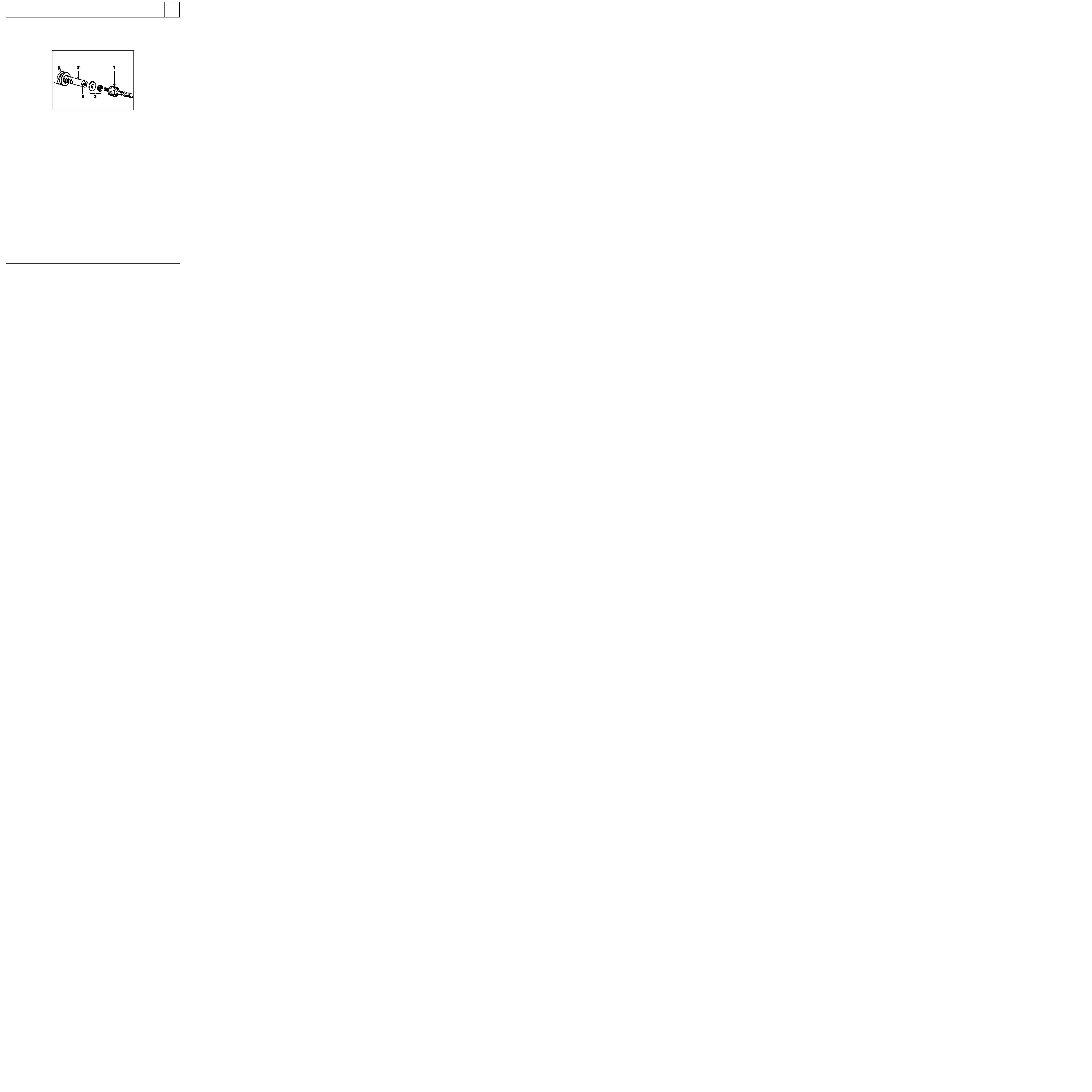
STEERING ASSEMBLY
Axial ball joint
36
REFITTING
Assembly (2)
MUST
be renewed systematically.
83510-1R3
Refit to the rack (3) :
- the stop washer assembled with the locking
ring (2),
- the new axial ball joint (1) having lightly coated
the threads with
LOCTITE FREN-BLOC
, ensuring
that the air evacuation opening is not blocked.
Before finally tightening the axial ball joint using
tool Dir. 1305-01, check that the tabs on the
locking ring (2) align with the flats (B) on the rack.
Tighten the axial ball joint to the recommended
torque.
Centre the steering to equalise the air in the
gaiters.
Fit a new gaiter and secure it with a new clip
(after greasing the gaiter bearing surface on the
axial ball joint).
Checking
Gently press on the gaiter to check the other
gaiter inflates which indicates the air is circulating
correctly.
36-2

STEERING ASSEMBLY
Manual steering rack
36
Put the vehicle on a two post lift.
REMOVAL
Remove the front wheels.
Cut the rubber gaiter retaining clip and push the
gaiter back towards the bulkhead.
Disconnect the ball joints using tool T.Av. 476.
Remove:
-
the universal joint eccentric bolt,
-
the steering rack mounting bolts on the sub-
frame.
Remove the steering rack.
SPECIAL TOOLING REQUIRED
Wheel bolts
9
Track rod end nut
3.7
Steering rack mounting bolts
5.5
Universal joint eccentric bolt
2.5
T.Av. 476
Ball joint extractor
TIGHTENING TORQUES (in daN.m)
REFITTING
Refitting is the reverse of removal. Observe the
recommended tightening torques.
If a new steering rack is being fitted, fit the track
rod ends in the position noted on removal.
To do this, slacken the bolt on the parallelism
adjustment sleeve and slacken the track rod end
while holding the axial ball joint using an open
wrench.
Make a mark or count the number of turns of
thread taken up so the parallelism can be pre-
adjusted on refitting.
Check the parallelism.
NOTE
: the markings on the track rod ends
M U S T
BE OBSERVED
(one mark on right hand joint, two
marks on left hand joint).
36-3

STEERING ASSEMBLY
Power assisted steering rack
36
SPECIAL TOOLING REQUIRED
Mot. 453-01
Hose clamp pliers
T.Av. 476
Ball joint extractor
Wheel bolts
9
Track rod end nut
3.7
Steering rack mounting bolt
5
Universal joint eccentric bolt
2.5
Engine tie bar bolt
6.5
TIGHTENING TORQUES (in daN.m)
Put the vehicle on a two post lift.
REMOVAL
Remove the front wheels.
Fit a clamp Mot. 453-01 to each of the pipes from
the oil reservoir.
NOTE :
never clamp the high pressure pipes.
Cut the rubber gaiter retaining clip and push the
gaiter back towards the bulkhead.
Disconnect the ball joints using tool T.Av. 476.
Remove the universal joint eccentric bolt.
Disconnect the oxygen sensor.
Remove the exhaust downpipe.
Remove the bolt (engine side) from the engine tie
bar and pivot the engine and transmission
assembly forwards.
Insert a retaining block.
Special notes for F8Q engine
Remove (from above) :
-
the battery,
-
the battery mounting,
-
the high and low pressure pipes from the
steering valve.
13120S
36-4
STEERING ASSEMBLY
Power assisted steering rack
36
Disconnect the high and low pressure pipes on the
steering rack (take precautions to catch the oil)
and the nut on the pipe retaining bracket.
Remove:
-
the two nuts on the heat shield for the right
hand steering rack bearing,
-
the steering rack mounting nuts and remove it
from the timing side.
NOTE
:
-
do not remove the pipes between the valve
and cylinder,
-
fit plugs to the steering rack openings to
prevent the introduction of impurities.
12997R
REFITTING
Refitting is the reverse of removal. Observe the
recommended tightening torques.
Fill the circuit with oil.
Turn the wheels from left to right (engine not
running) to distribute the oil in the circuit.
Repeat the operation with the engine running
then top up the level.
If a new steering rack is being fitted, fit the track
rod ends in the position noted on removal.
To do this, slacken the bolt on the parallelism
adjustment sleeve and slacken the track rod end
while holding the axial ball joint using an open
wrench.
Make a mark or count the number of turns of
thread taken up so the parallelism can be pre-
adjusted on refitting.
Check the parallelism.
36-5

STEERING ASSEMBLY
Gaiter
36
The gaiter
MUST
be renewed with a new gaiter
whenever an axial ball joint is removed.
Fitting the gaiter
Use an ogive on the axial ball joint to prevent
damage to the gaiter during fitting.
Coat the gaiter bearing face on the axial ball joint
with grease to prevent the gaiter twisting.
Secure the gaiter with a new clip (supplied with
the gaiter).
NOTE
: the steering
MUST
be at the centre point
to equalise the air.
36-6
STEERING ASSEMBLY
Steering pushrod
36
1.
Determining the source of the noise
Hold the steering rack on the pinion side and
check for transverse play (up and down).
Movement followed by a click is caused by the
pinion.
2.
Adjusting for SMI steering racks
Release the adjusting nut (1) by straightening the
bent over edges (A) on the nut collar.
Check when driving that the steering returns to
the centre point.
Maximum adjustment allowed : 1 notch.
Lock the nut again in the two lugs opposite the
housing by bending over the nut collar.
A D J U S T M E N T
If the steering rack pinion is noisy, before considering replacing the steering rack, check that the pinion is
correctly adjusted.
83920R
36-7
STEERING ASSEMBLY
Manual steering assistance pump
36
SPECIAL TOOLING REQUIRED
Dir. 1083
Tool for refitting the PAS pump
pulley
B.Vi. 22-01
+
Tool for removing the PAS pump
pulley
B.Vi. 47
12996R
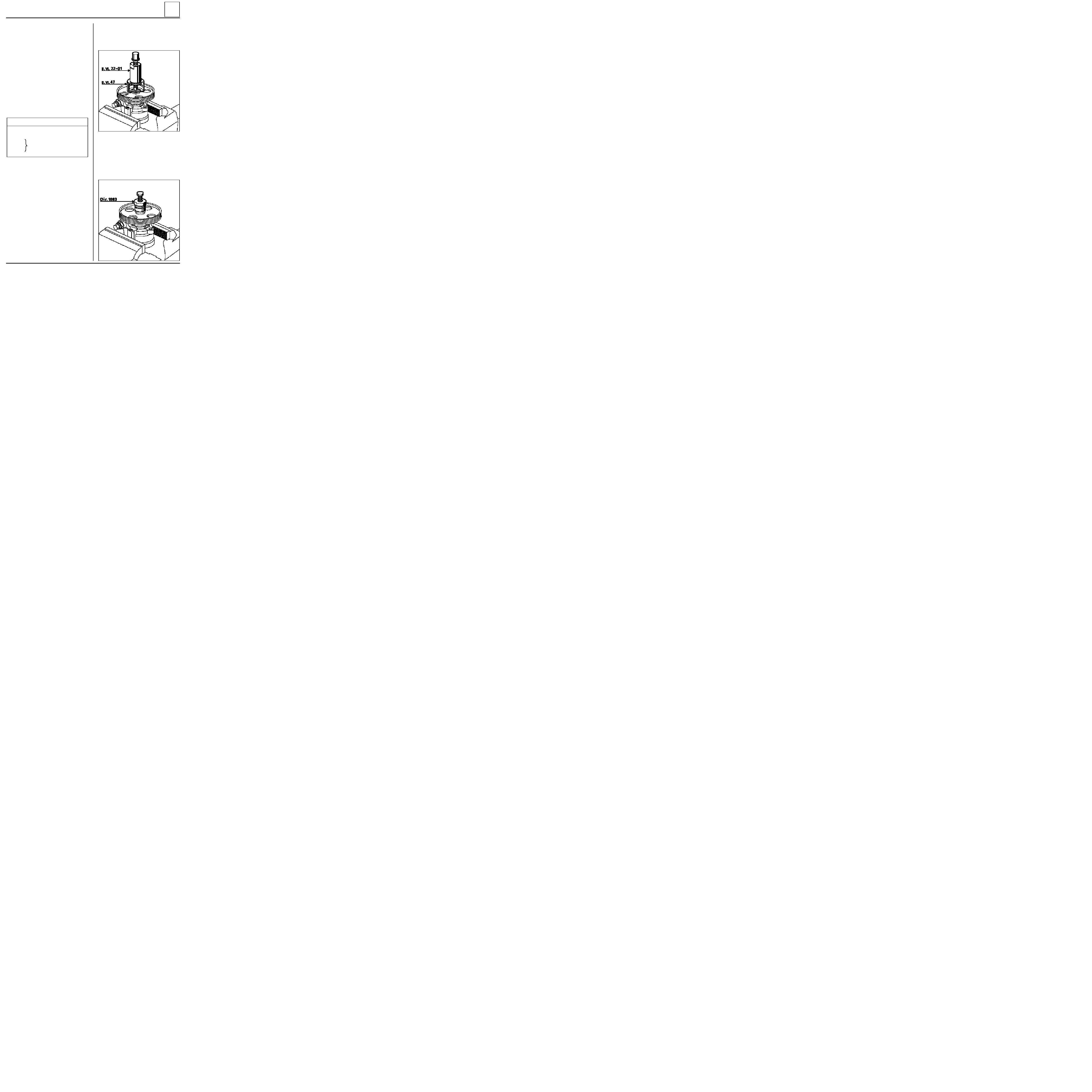
REPLACING THE PULLEY (D7F-F8Q engine without
A C )
REMOVAL
Remove:
-
the PAS pump belt.
-
the pulley (three bolts).
REFITTING
Refitting is the reverse of removal. Observe the
procedure for tensioning the belt (see section 07).
REPLACING THE PULLEY ( E7J engine without AC)
REMOVAL
With the pump removed (see removal method on
following pages), set it in a vice and extract the
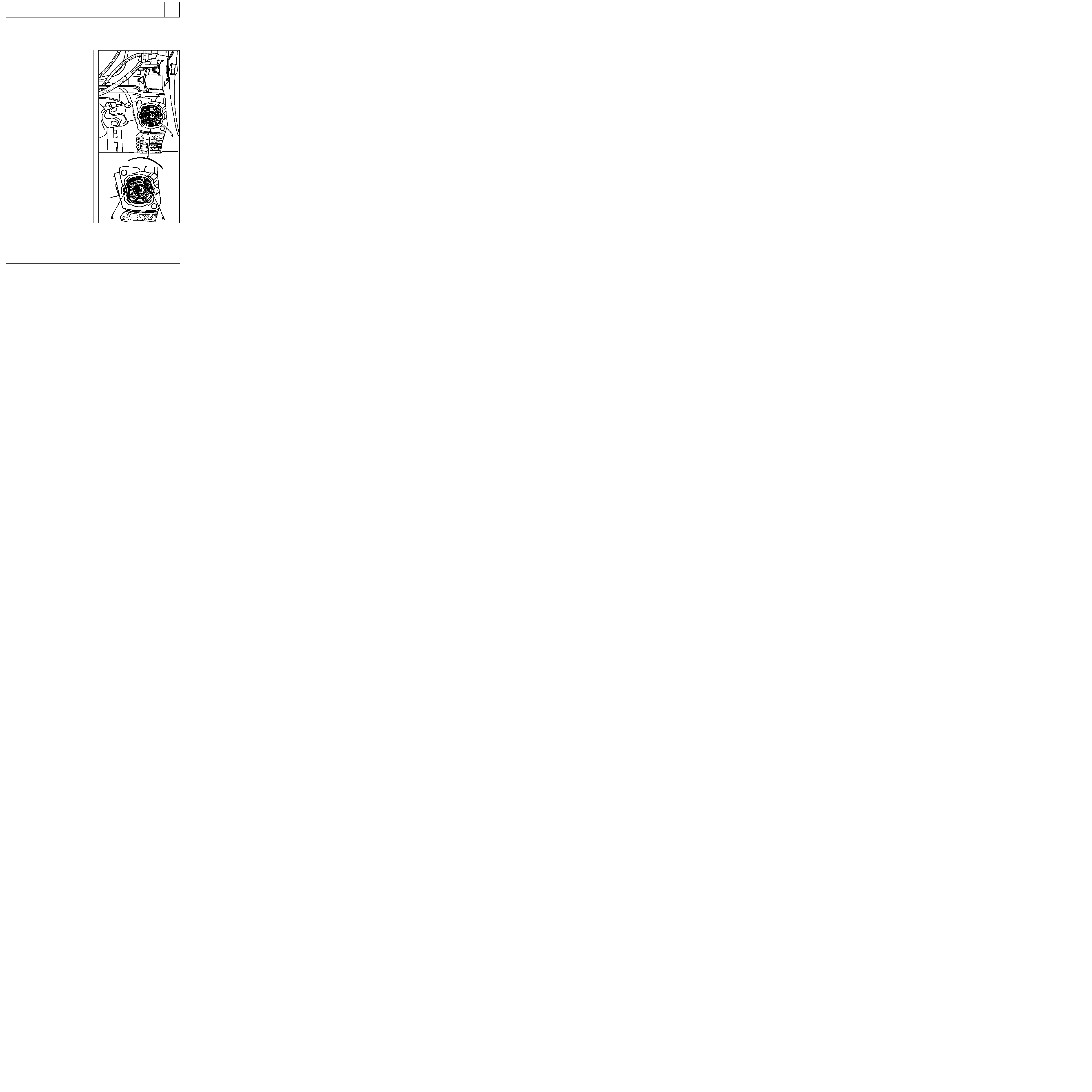
pulley using tools B.Vi. 22-01 + B.Vi. 47.
12995R
REFITTING
Refit the pulley using tool Dir. 1083.
Press the pulley on to dimension:
X
=
34.7
±
0.2
36-8

STEERING ASSEMBLY
Manual steering assistance pump
36
SPECIAL TOOLING REQUIRED
Mot. 453-01
Hose clamp pliers
T. Ar. 1094
Extractor
Put the vehicle on a two post lift.
REMOVAL
Remove:
-
the PAS pump belt,
-
the pulley.
Fit a clamp Mot. 453-01 to the supply pipe.
Disconnect the supply and high pressure pipes.
Take precautions to catch the PAS fluid (protect
the alternator).
Remove the three pump mounting bolts and
remove the pump.
REFITTING
Refitting is the reverse of removal. Observe the
procedure for tensioning the belt (see section 07).
Fill and bleed the circuit, moving the steering
from lock to lock.
D7F engine
without AC
36-9

STEERING ASSEMBLY
Manual steering assistance pump
36
SPECIAL TOOLING REQUIRED
Mot. 453-01
Hose clamp pliers
Put the vehicle on a two post lift.
REMOVAL
Remove:
-
the right hand wheel,
-
the right hand mudguard,
-
the bumper (10 bolts).
-
the accessories belt,
-
the pulley.
Fit a clamp Mot. 453-01 to the supply pipe.
Disconnect the supply and high pressure pipes.
Take precautions to catch the PAS fluid.
Remove the three pump mounting bolts and
remove the pump.
REFITTING
Refitting is the reverse of removal. Observe the
procedure for tensioning the belt (see section 07).
Fill and bleed the circuit, moving the steering
from lock to lock.
F8Q engine
without AC
36-10
STEERING ASSEMBLY
Manual steering assistance pump
36
SPECIAL TOOLING REQUIRED
Mot. 453-01
Hose clamp pliers
Put the vehicle on a two post lift.
REMOVAL
Remove:
-
the alternator belt,
-
the PAS pump belt,
-
the alternator.
Fit a clamp Mot. 453-01 to the supply pipe.
Disconnect the supply and high pressure pipes.
Take precautions to catch the PAS fluid.
Remove the three pump mounting bolts and
remove the pump.
REFITTING
Refitting is the reverse of removal. Observe the
procedure for tensioning the belt (see section 07).
Fill and bleed the circuit, moving the steering
from lock to lock.
13296R
E7J engine
without AC
36-11
STEERING ASSEMBLY
Steering column
36
TIGHTENING TORQUES (in daN.m)
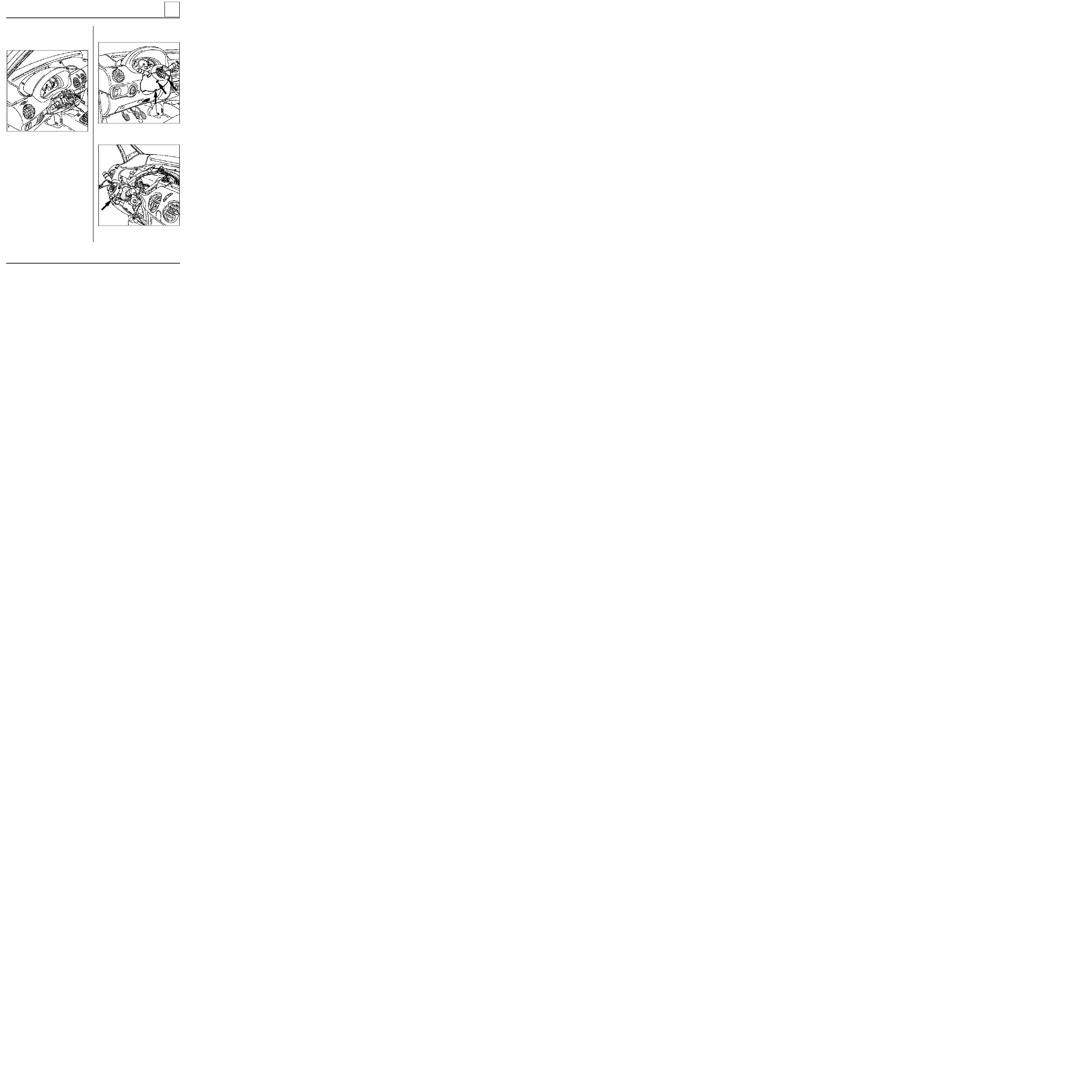
REMOVAL
Disconnect the battery.
Set the vehicle wheels straight.
Remove the steering wheel in the following
manner.
Without airbag option
Remove the plastic cover.
Remove:
- the steering wheel bolt (this
MUST
be renewed
on refitting),
- the steering wheel after noting its position.
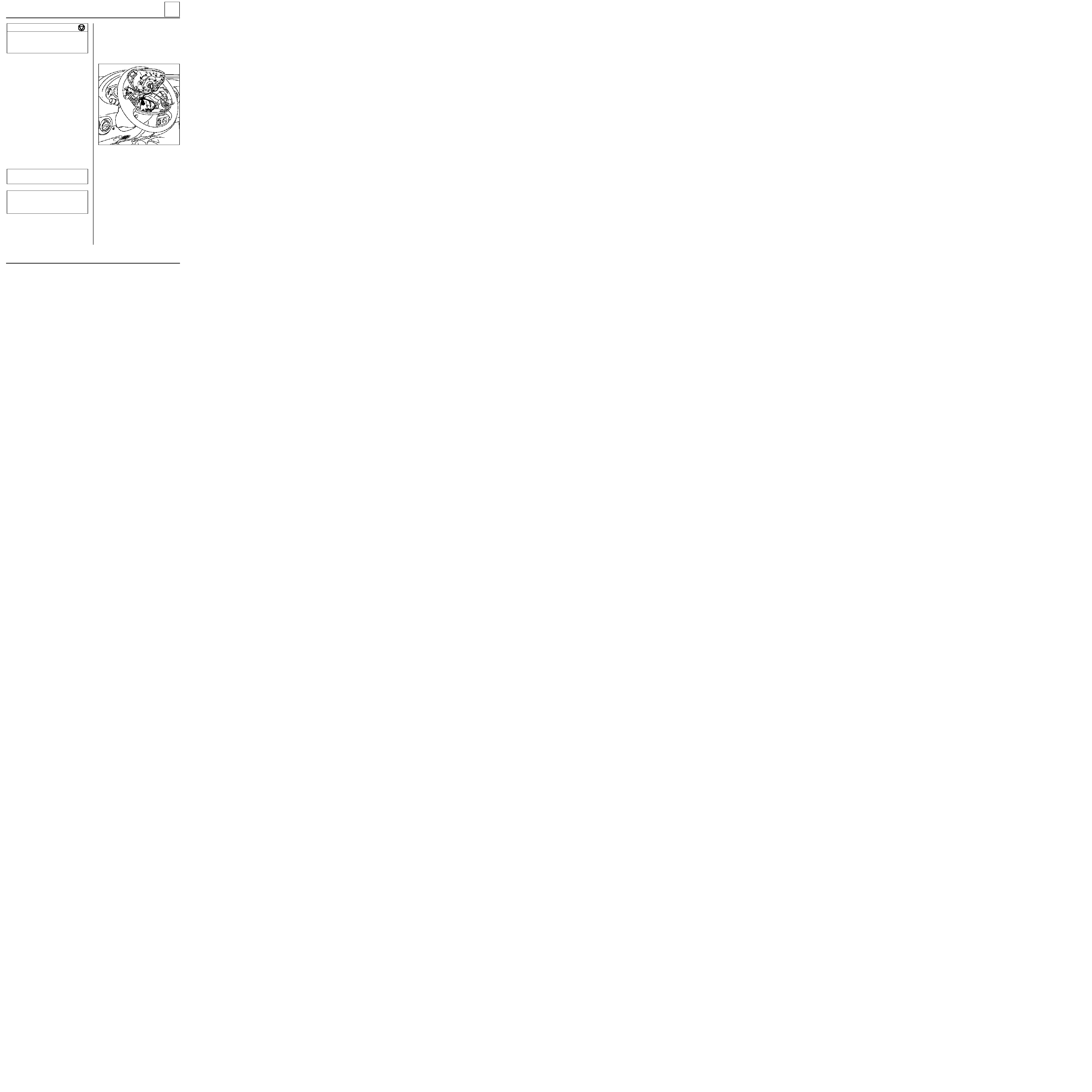
With airbag option
REMOVAL
Disconnect the battery.
Remove:
- the driver’s airbag cushion by the two Torx T30
bolts (tightening torque 0.5 daN.m) located
behind the steering wheel and disconnect the
connector ( D ),
IMPORTANT:
pyrotechnic systems (airbags and
pretensioners) must not be handled near to a heat
source or flame - they may be triggered.
IMPORTANT :
whenever the steering wheel is
removed, the airbag connector ( D )
MUST
be
disconnected. The airbag is fitted with a
connector which short circuits when it is
connected to avoid any incorrect triggering.
12973S
- the horn connector, if fitted,
- the steering wheel bolt (this
MUST
be renewed
on refitting),
- the steering wheel after setting the wheels
straight,
- the half cowlings ( three bolts).
Disconnect the rotary switch connector and
remove it after removing the three mounting
bolts ( E ).
When removing the switch, its position must be
noted:
• either by ensuring the wheels are straight when
removing it so that the track may be positioned
centrally,
• or by immobilising the rotary switch rotor with
adhesive tape.
Steering wheel bolt
4.5
Steering column universal joint
eccentric bolt
2.5
Steering column mounting nuts
2
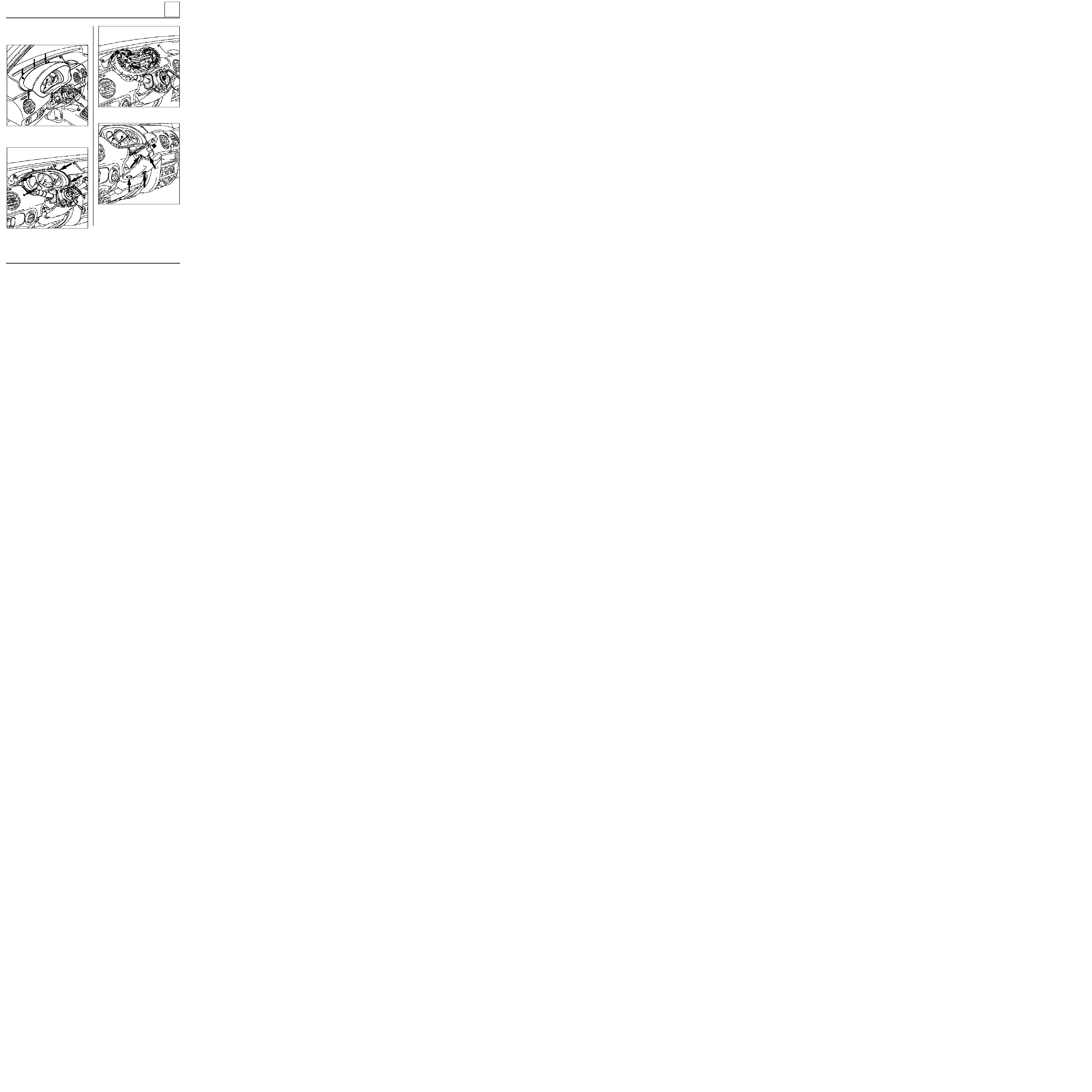
36-12
STEERING ASSEMBLY
Steering column
36
If the switch is being replaced, the new part is
supplied ready-centred, held in place by an
adhesive label which tears off when the steering
wheel is moved for the first time (fit with the
wheels straight).
12970S
Remove:
-
the half cowlings (three bolts),
-
the stalk - switch assembly (one bolt).
12967-1R
12971R
Disconnect the connectors.
36-13
STEERING ASSEMBLY
Steering column
36
Remove:
-
the instrument panel visor ( six bolts).
12970-1R1
-
the four mounting bolts for the instrument
panel and disconnect the connectors.
12969-1R1
12968S
-
the lower protector ( four bolts).
12966R
36-14
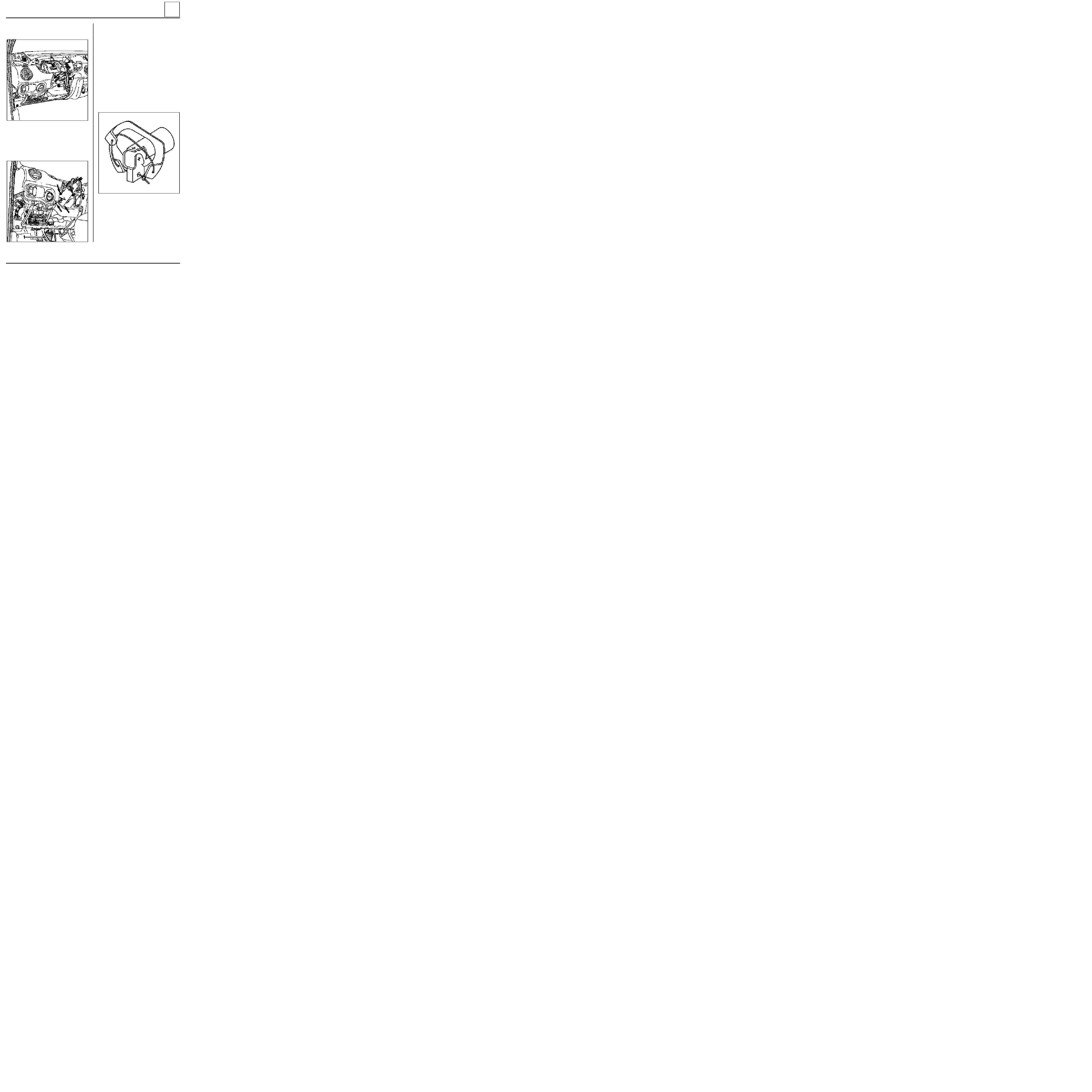
STEERING ASSEMBLY
Steering column
36
Under the vehicle, cut the retaining clip for the
rubber gaiter and push it back towards the
bulkhead.
Remove the eccentric bolt from the universal
joint.
Remove the two bolts and the two nuts mounting
the steering column.
12964R2
12965-1R2
Release:
-
the steering column after disconnecting the
ignition switch,
-
the gaiter from the bulkhead ( 1 ) and remove
it with the steering column.
REFITTING
Refit the steering column.
Fit the gaiter on the bulkhead, having tied the
flaps and the universal joint together with string.
Refitting is then the reverse of removal.
Check the instrument panel connectors are
correctly reconnected.
13116S
Remove the mounting bolts for the dashboard on
the steering column.
36-15

STEERING ASSEMBLY
Steering column
36
IMPORTANT : if these instructions are not
followed exactly the system may not operate
normally and could even be triggered incorrectly.
IMPORTANT
Before reconnecting the driver’s airbag cushion,
check to see if the system is operating correctly as
follows:
•
check the airbag warning light on the
instrument panel is illuminated when the
ignition is on,
•
connect a dummy ignition module to the
driver’s airbag connector and check that the
warning light extinguishes,
•
switch the ignition off, connect the airbag
cushion in place of the dummy ignition module
and secure the cushion to the steering wheel,
•
switch the ignition on. Check the warning light
illuminates for three seconds when the ignition
is switched on then extinguishes and remains
extinguished.
If the warning light does not operate as described
above, refer to the fault finding section and check
the system using the
XRBAG
(Elé. 1288).
SPECIAL NOTES FOR VEHICLES FITTED WITH A
DRIVER’S AIRBAG
Ensure that the wheels are still straight.
Check that the rotary switch is still immobilised
before refitting.
If it is not, follow the method for centring
described in section 88 "driver’s airbag".
Renew the steering wheel bolt each time it is
removed ( pre-bonded bolt).
Observe the correct tightening torque ( 4.5
daN.m
).
36-16
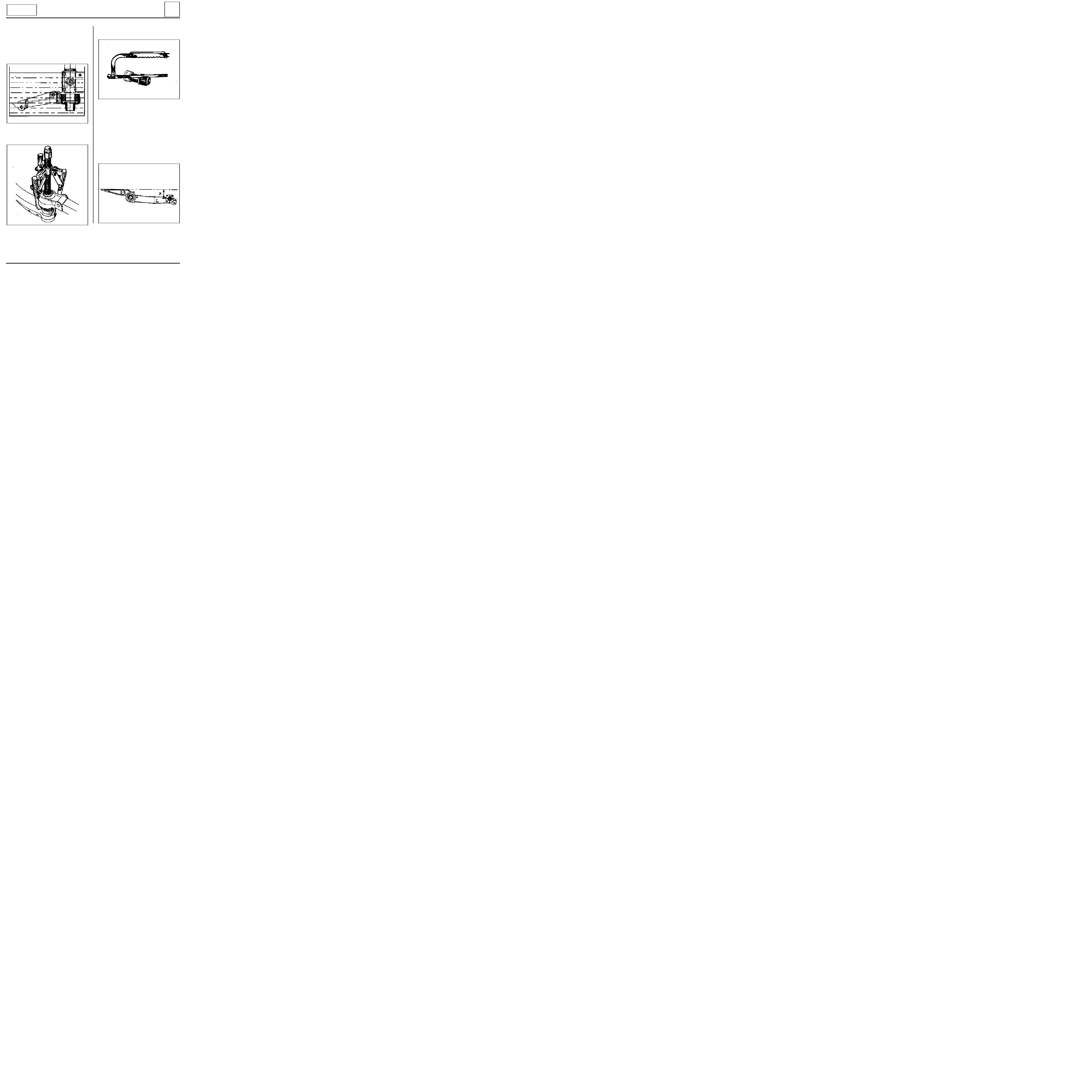
MECHANICAL ELEMENT CONTROLS
Master cylinder
37
Hydraulic pipe unions
1.7
Mounting nut on brake servo
1.8
REMOVAL
Disconnect the battery.
Disconnect the brake fluid level detector
connector.
Remove the injection computer (depending on
version).
Release the PAS reservoir and move it to the side,
towards the engine.
Drain and remove, by pulling up, the brake fluid
reservoir (take care to catch the fluid which will
run out).
Remove:
- the pipes and note their positions,
- the two mounting nuts on the brake servo.
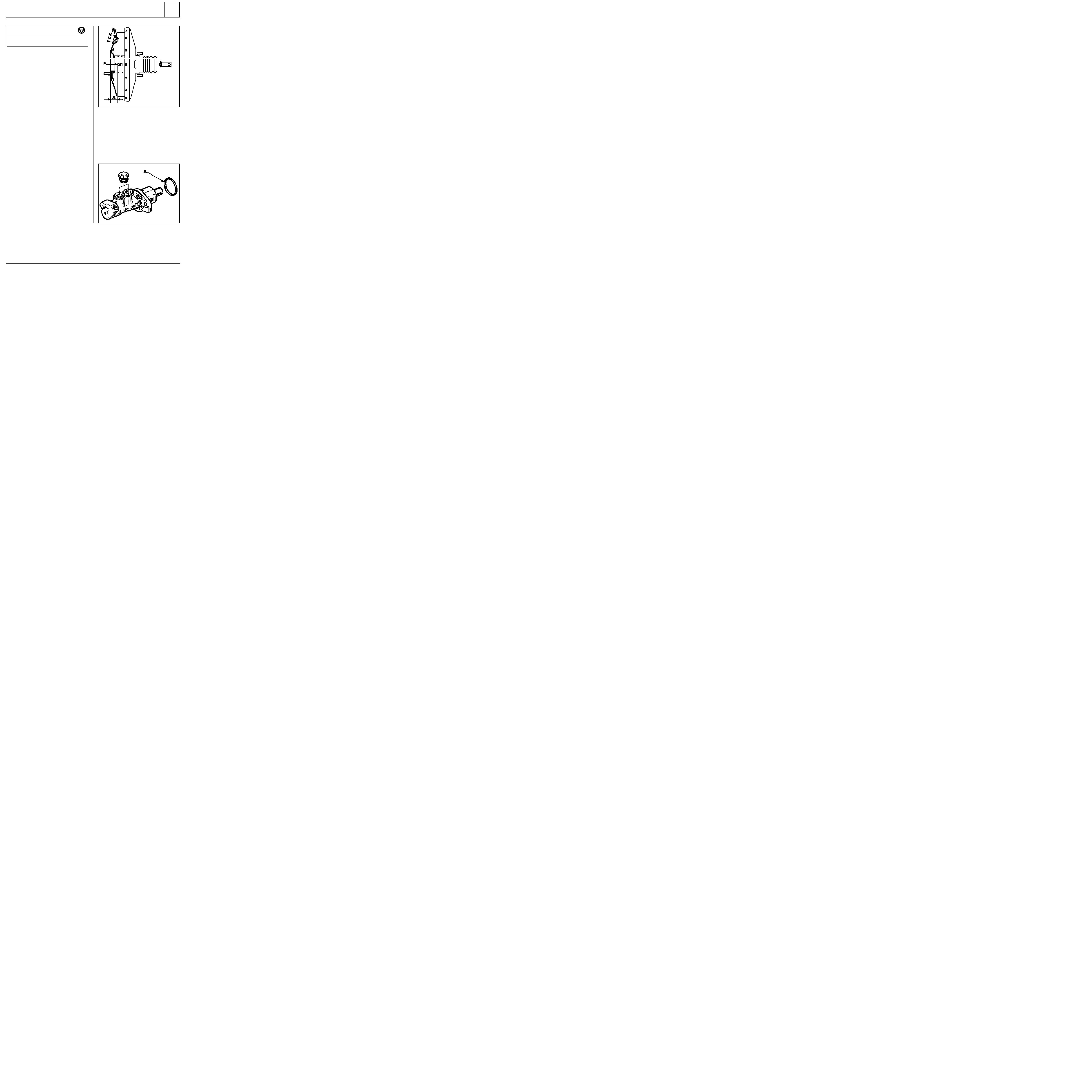
REFITTING
Refitting is the reverse of removal.
Check the length of the pushrod.
Dimension X = 22.3 mm.
Depending on model, adjust using pin (P).
91101R
NOTE :
these vehicles have a master cylinder
which is integral to the brake servo. Sealing of the
brake servo is directly linked to that of the master
cylinder. During any operation, a new seal (A)
must be fitted.
Fit the master cylinder in alignment with the
brake servo so that pushrod pin (P) enters
correctly into the master cylinder housing.
TIGHTENING TORQUES (in daN.m)
DI3718
37-1

MECHANICAL ELEMENT CONTROLS
Master cylinder
37
Fill the brake fluid reservoir and bleed the brake
circuit.
MASTER CYLINDER (EXCHANGE)
The kit sold by the Parts Department comprises :
- one master cylinder (4 outlets or 2 outlets for
ABS),
- two plugs (A),
- two mounting nuts (B).
DI3719
37-2
MECHANICAL ELEMENT CONTROLS
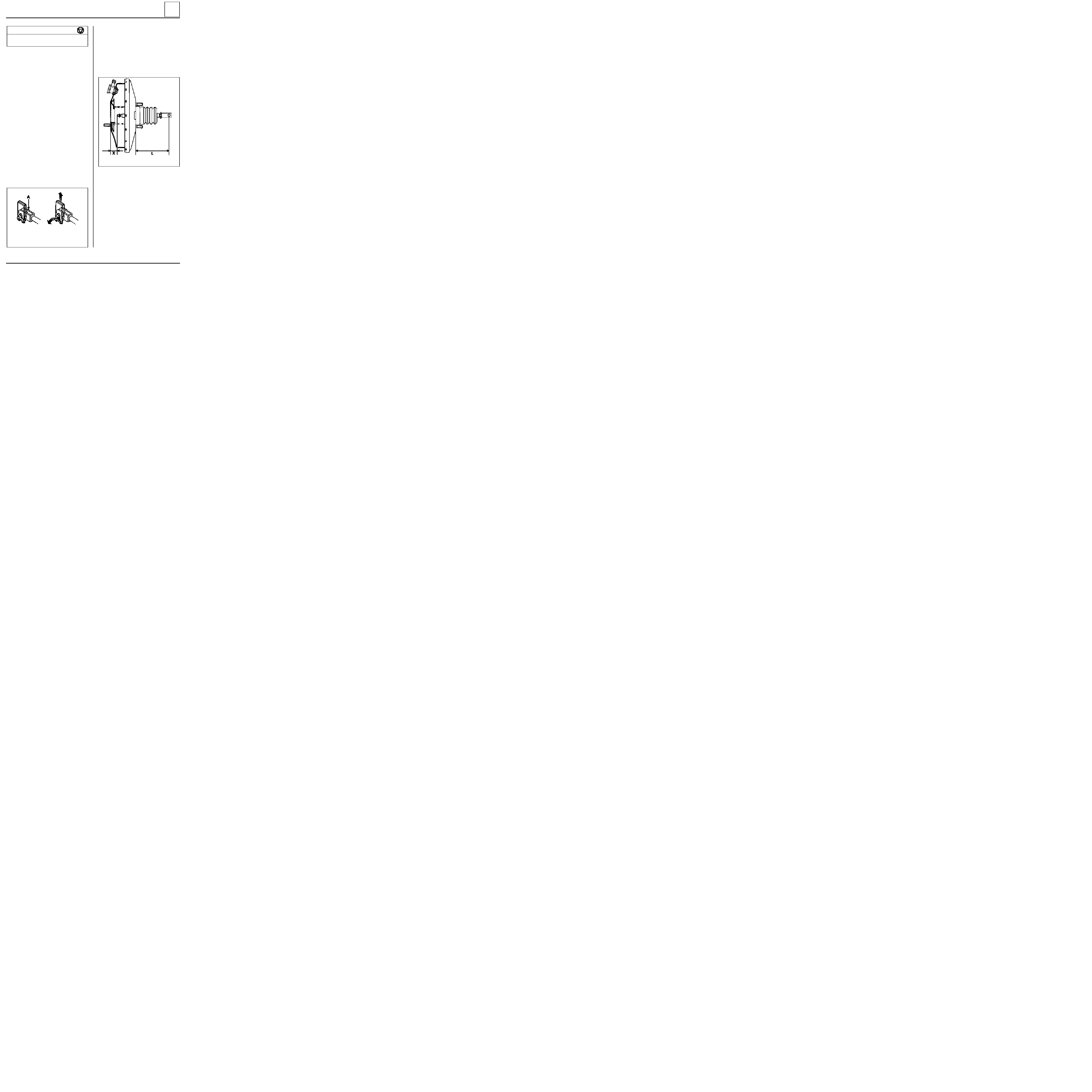
Brake servo
TIGHTENING TORQUES (in daN.m)
Mounting nut on brake servo
1.8
Brake servo on bulkhead
2.3
-
remove the 4 brake servo mounting nuts,
-
remove the brake servo.
REFITTING
Before refitting, check:
-
dimension L = 104.8 mm
,
-
dimension X = 22.3 mm
.
The brake servo cannot be repaired. Operations
are only allowed on:
-
the air filter,
-
the non-return valve.
REMOVAL
Disconnect and remove the battery.
Remove:
-
the master cylinder (following the method
described previously),
-
the battery protection plate (4 bolts, 1 nut),
-
the two mounting nuts for the expansion
bottle and move it towards the engine.
Disconnect the flexible vacuum hose from the
brake servo.
In the passenger compartment:
-
remove the pin ( A ) from the clevice
connecting the brake pedal to the pushrod by
moving the clip,
37
91101R2
97860R
Refitting is the reverse of removal.
Bleed the brake circuit.
37-3
SPECIAL TOOLING REQUIRED
Mot
453 -01
Hose clamp pliers
MECHANICAL ELEMENT CONTROLS
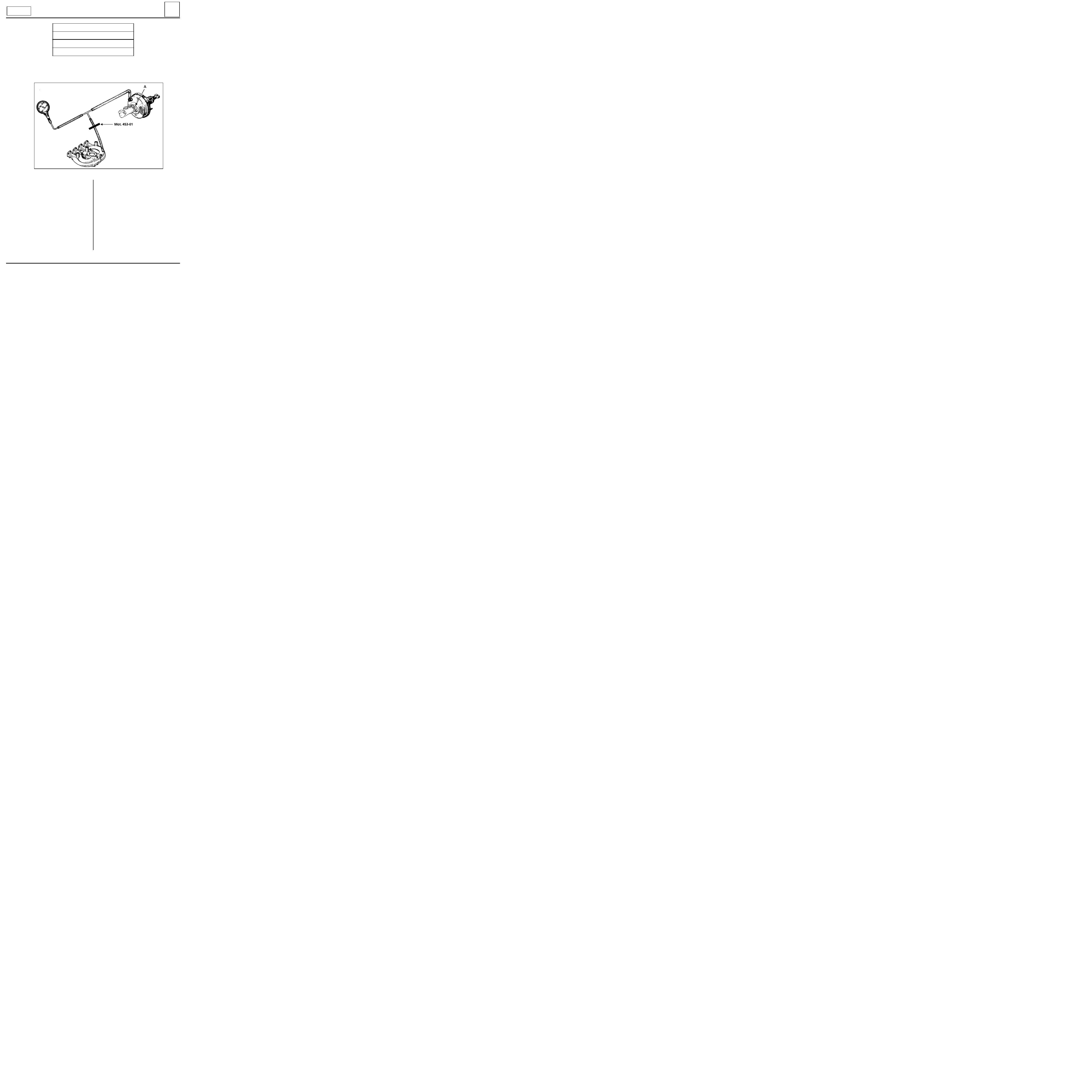
Brake servo
The sealing of the brake servo is checked on the
vehicle when the hydraulic circuit is in operating
condition.
Connect the vacuum pump between the brake
servo and the vacuum source (inlet manifold)
using a "T" union and the shortest possible pipe.
Run the engine at idle speed for one minute.
Clamp the pipe (clamp Mot. 453-01) between the
"T" union and the vacuum source.
Turn the engine off.
If the vacuum drops by more than 33 mbar (25
mm/Hg) in 15 seconds, there is a leak located
either :
-
at the non-return valve (replace it),
-
or at the pushrod diaphragm (replace the
brake servo).
If the brake servo is not operational the braking
system will operate but the force required at the
pedal to obtain the equivalent deceleration as for
assisted braking is considerably higher .
CHECKING SEALING
When checking the sealing of the brake servo, ensure the seal between the brake servo and the master
cylinder is perfect. If there is a leak, replace the seal (A).
37
DI3701
EQUIPMENT REQUIRED
Vacuum pump
Petrol engine
37-4
83 212
75 564
MECHANICAL ELEMENT CONTROLS
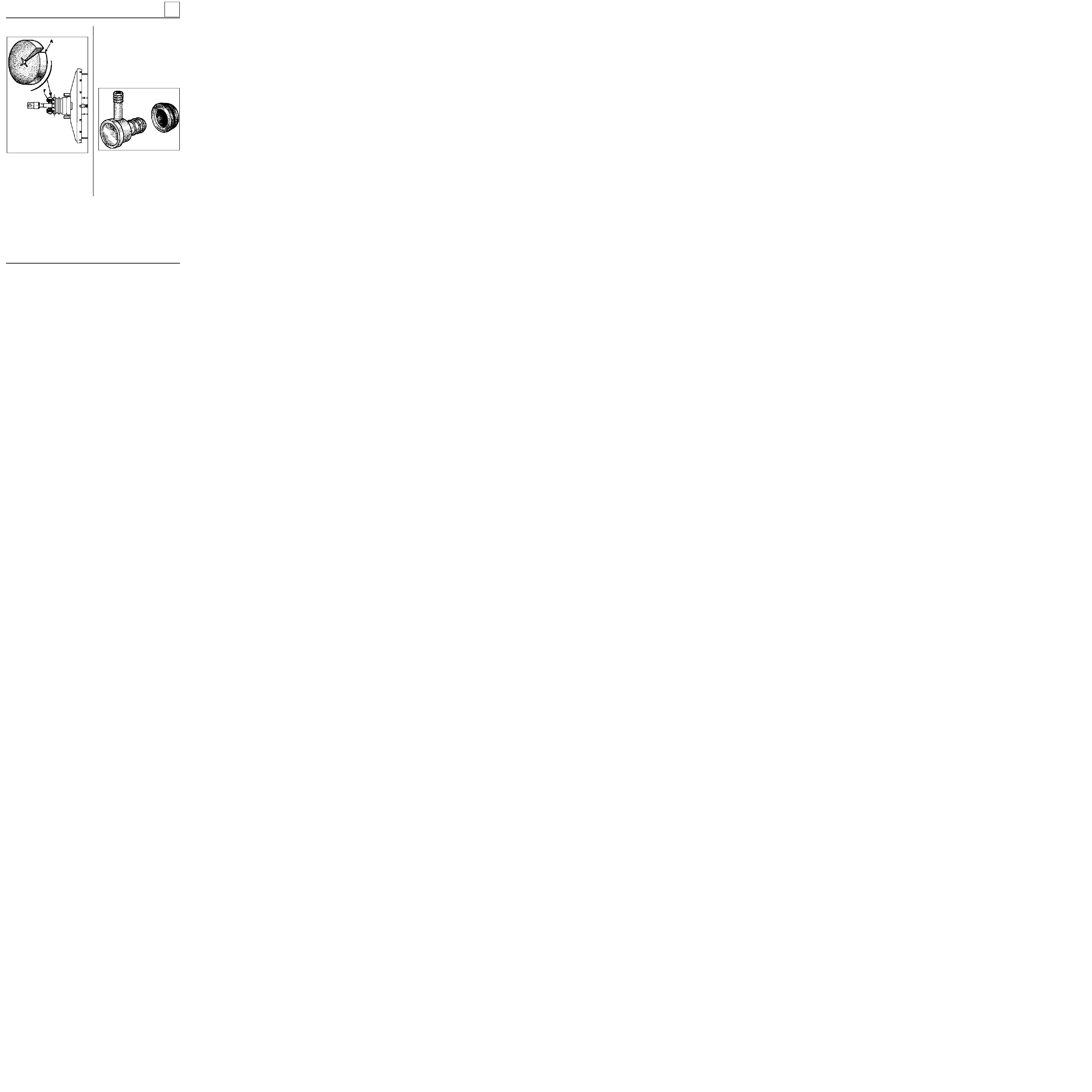
Air filter - Brake servo non-return valve
REPLACING THE AIR FILTER
To replace the air filter (F), the brake servo does
not need to be removed.
Under the pedal mounting, use a screwdriver or a
metal hook to remove the worn filter (F). Cut the
new filter at A (see diagram) and fit it around the
rod, then press it into position, checking that it
fills the complete opening to prevent any non-
filtered air from passing through.
REPLACING THE NON-RETURN VALVE
This operation may be carried out on the vehicle.
REMOVAL
Disconnect the brake servo vacuum inlet pipe.
Pull the non-return valve while twisting it to
release it from the rubber sealing washer.
REFITTING
Check the condition of the rubber sealing washer
and the non-return valve.
Replace any faulty parts.
Refit the assembly into position.
37
91101G
74883S
37-5
MECHANICAL ELEMENT CONTROLS
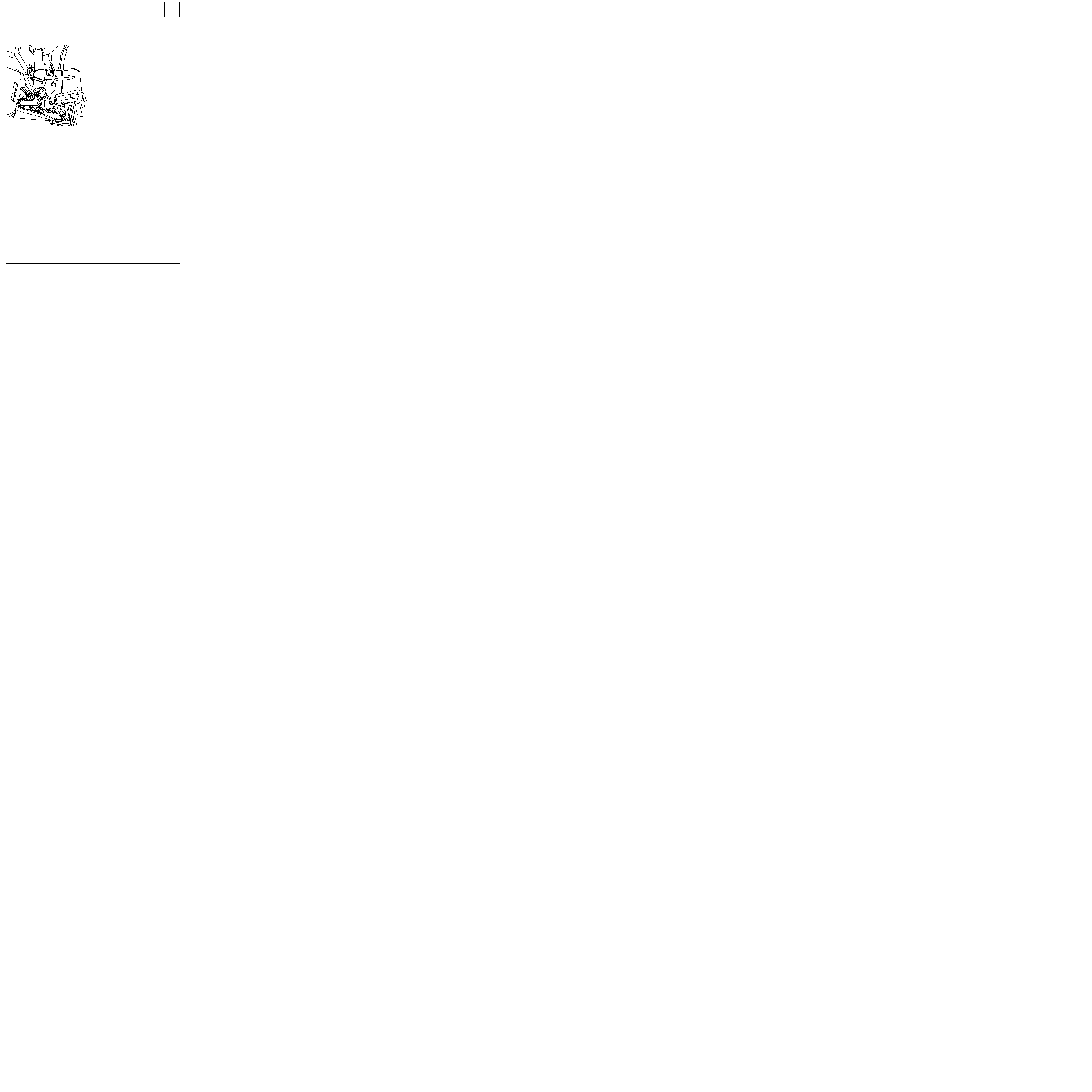
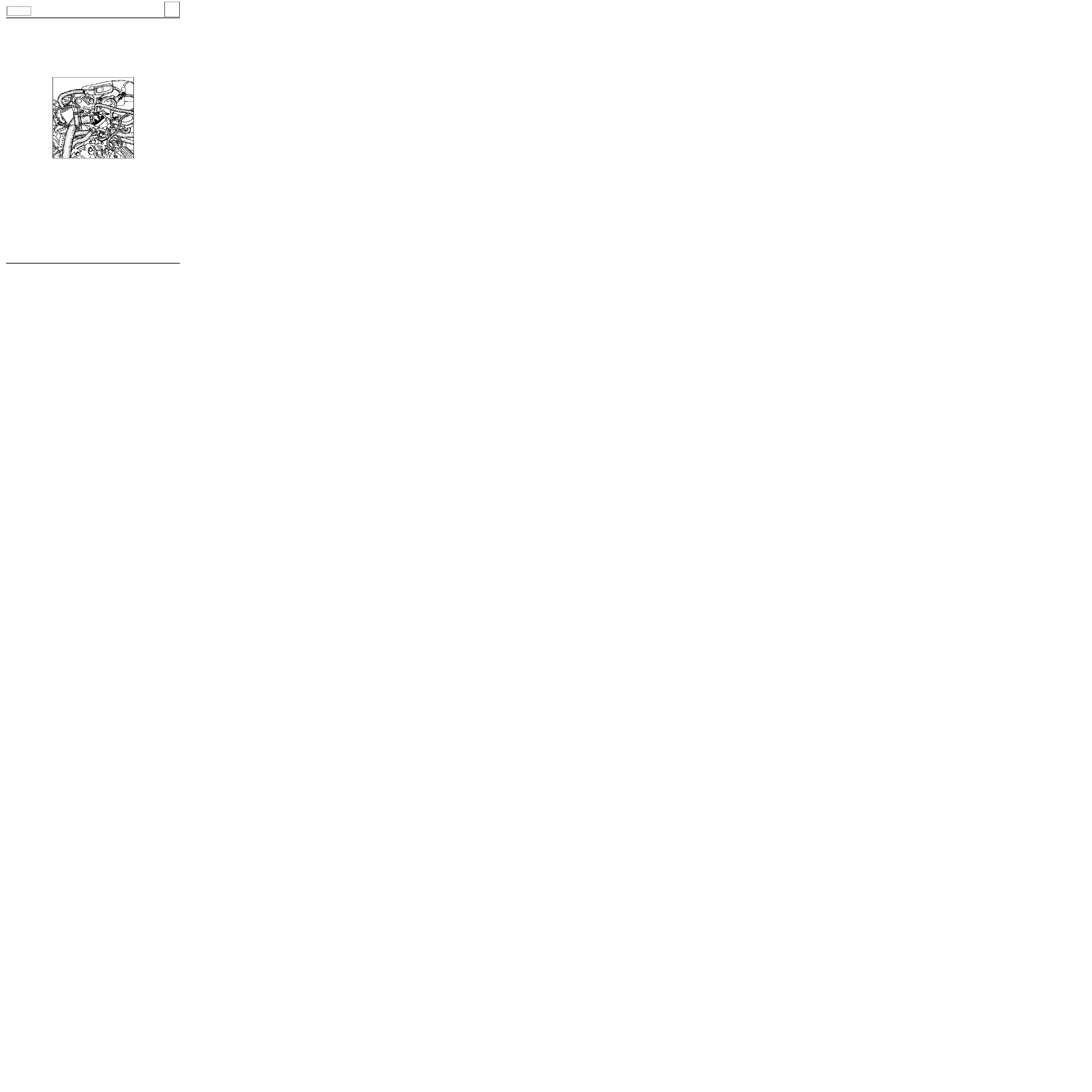
Vacuum pump
37
REMOVAL
Drain the cooling circuit.
Remove the air tube and its mounting.
Disconnect the quick release vacuum pipe.
Remove the thermostat mounting (2 bolts).
Remove the vacuum pump (2 bolts, 2 nuts).
13097-1S
Systematically renew the drive dog when repla-
cing the pump.
REFITTING
Refitting is the reverse of removal.
Bleed the brake circuit.
CHECKING
Engine warm, at 4000 rpm, the minimum vacuum
should be 700 mbar (525 mm/Hg) in 3 seconds.
Diesel engine
37-6
MECHANICAL ELEMENT CONTROLS
Handbrake control lever
37
REMOVAL
Release the handbrake.
Remove the lower bolts from the exhaust
downpipe.
Remove the rear rubber mounting for the exhaust
pipe.
NOTE
: attach the exhaust pipe to the body.
Remove the heat shields.
12998S
98826-2R
Note the handbrake adjustment dimen-
sion,between the end of the nut (1) and the rod.
Slacken nut ( 1 )to release the two cables.
Remove the linkage from the clip (2).
Remove the two handbrake control lever
mounting nuts.
Remove the handbrake lever and disconnect the
connector.
REFITTING
Refitting is the reverse of removal.
Refit the heat shields.
Remember to reconnect the handbrake
connector.
Reset the handbrake control linkage to the
dimension noted on removal.
If necessary, adjust the lever travel (see section
"Adjusting the control"
).
37-7
MECHANICAL ELEMENT CONTROLS
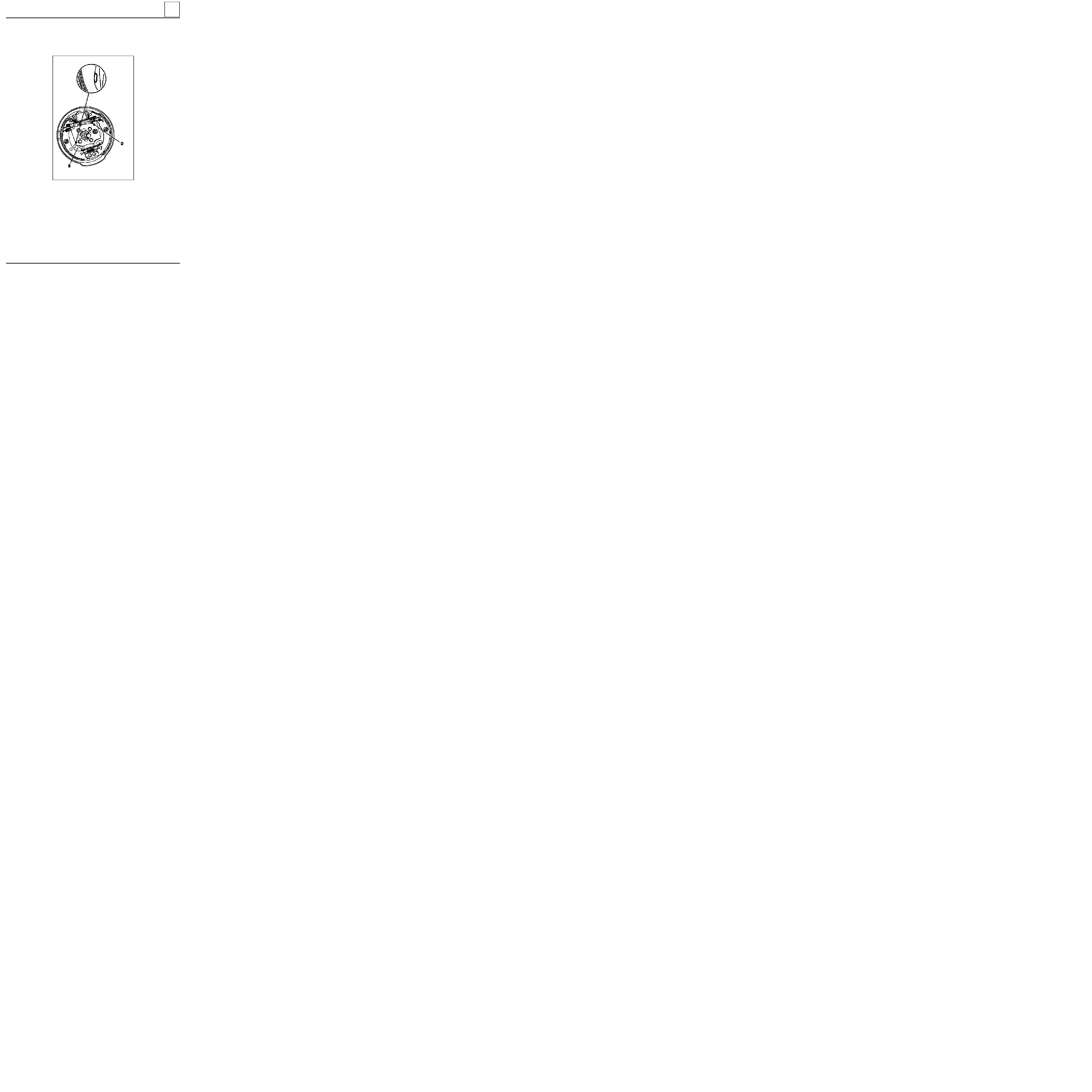
Handbrake control
37
A D J U S T M E N T
Incorrect adjustment of the handbrake where the
cable is too tight:
- prevents the correct operation of the automa-
tic compensation system for the brake shoes ,
- causes long brake pedal travel.
The cables should not be re-tensioned to correct
this fault since it will quickly occur again.
The handbrake should not be used to adjust play,
it should only be adjusted when replacing :
- brake linings,
- cables,
- the control lever.
Any other adjustment except in the above cases is
not permitted.
With the vehicle on a lift supported under the bo-
dy, slacken the nut (1) so the central adjuster is
completely free.
Remove:
- the two rear wheels,
- the two drums.
Check the operation of the compensation system
by rotating the notched sector (D) (ensure it turns
in both directions), then turn it back by 5 to 6
teeth.
98992-1R3
98826-1R
37-8
MECHANICAL ELEMENT CONTROLS
Handbrake control
37
98992-1R2
Ensure :
- the cables slide correctly,
- the handbrake levers (B) are in the correct
position against the brake shoes.
Progressively tighten the cables at the central
adjuster so that levers (B) start to move between
the 1st and 2nd notch
of the control lever travel
and remain applied from the 2nd notch.
Tighten the lock nuts.
Fit the drums.
With the vehicle on its wheels, adjust the brake
linings by pressing the brake pedal firmly and
progressively for a number of times while
listening for the automatic compensation system
clicking.
37-9
96118R
MECHANICAL ELEMENT CONTROLS
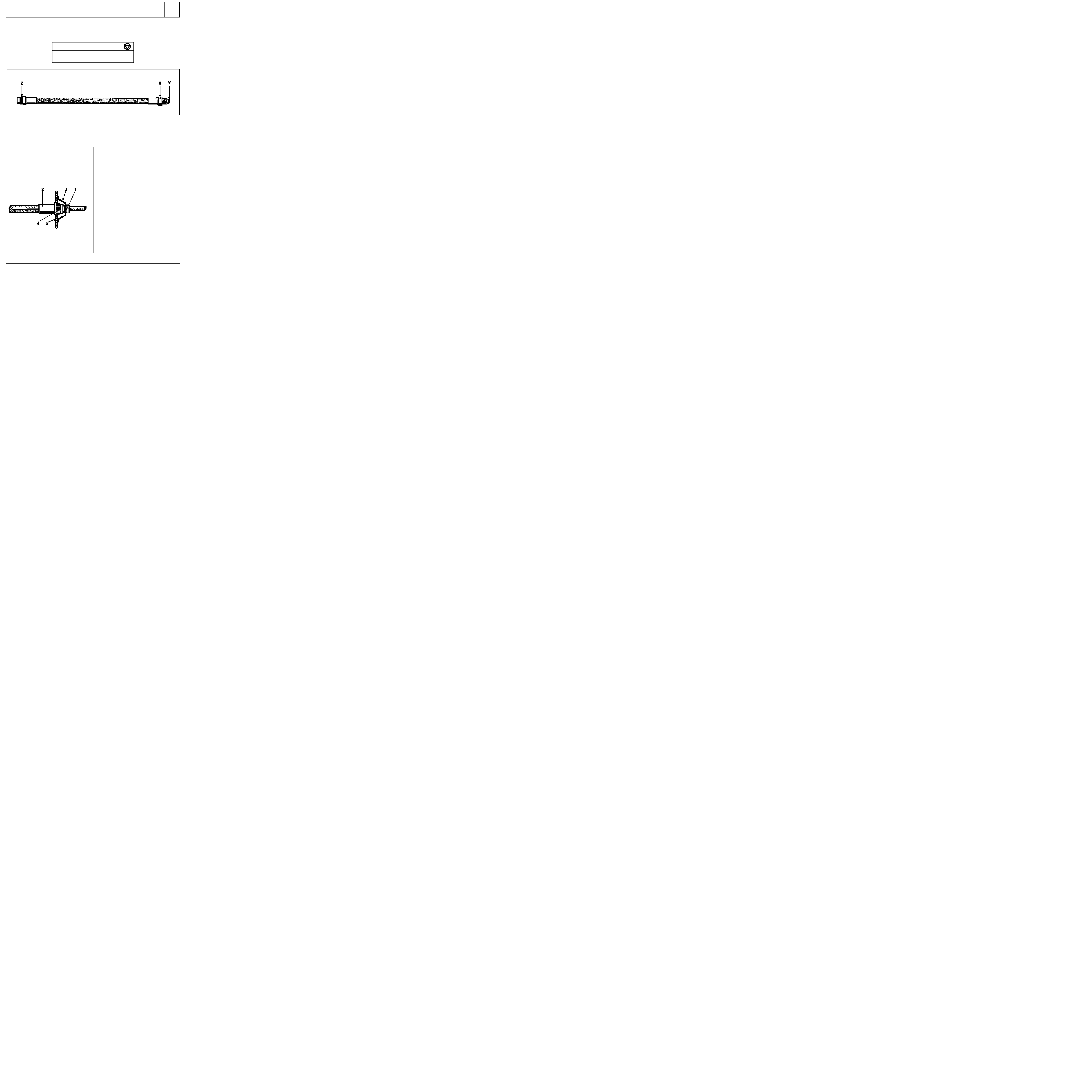
Brake pipes
37
These vehicles have brake pipes without a copper seal. The seal is by contact "at the bottom of the cone" of
the shoulder (Y) on the pipe.
X = 1.5
Z= 1.3
TIGHTENING TORQUES (in daN.m)
PRECAUTIONS TO BE TAKEN WHEN REMOVING - REFITTING A BRAKE CYLINDER OR A BRAKE PIPE.
For safety reasons and to ensure that the brake pipe is not twisted and is not liable to touch a suspension
component the following order of operations must be observed:
Remove the hose from the caliper and if necessary
remove the caliper.
REMOVAL
Slacken the union (1) (pipe wrench) between the
rigid pipe and the hose (2) until the spring (3)
becomes slack which releases the hose from the
splines (4).
85536R
REFITTING
Fit the caliper to the brake and screw the hose
onto it, then torque tighten to
1.5 daN.m
.
The brake pipes are fitted when the axle assembly
is in position:
•
Wheels suspended (suspension in place)
•
Axle assembly aligned (wheels straight)
Position the female end of the hose on the
retaining bracket (5), without twisting it and
check that the end piece (4) fits freely into the
splines of the bracket, then fit:
- the spring (3),
- the rigid pipe to the hose, checking that the
hose does not turn when the assembly is
screwed together.
Torque tighten the union.
Bleed the brake circuit.
37-10

MECHANICAL ELEMENT CONTROLS
Braking compensator
37
CHECKING PRINCIPLE
These vehicle are fitted with a load sensitive
braking compensator.
The pressure is read in an X pattern, by comparing
the pressure at the rear wheels with a given
pressure at the front wheels.
The dual compensator has two totally separate
bodies which act in an X pattern on one front
wheel and one rear wheel.
Both circuits must be checked.
I :
front right/ rear left.
II :
front left/ rear right.
Load sensitive compensators
For load sensitive compensators, the adjustment
allows alteration of the rear pressure depending
on the front pressure.
The adjustment is made simultaneously in both
bodies. If the pressure is incorrect for one of the
two bodies, replace the compensator.
85925S
37-11
MECHANICAL ELEMENT CONTROLS
Braking compensator
37
N O T E
the braking compensators differ depending on the type of rear axle:
- standard load rear axle: red reference mark,
- increased load rear axle: green reference mark,
REMOVAL
Put the vehicle on a two post lift.
Disconnect the brake pipes.
Disconnect rod ( 2 ) from the compensator by
slackening bolt ( 1 ).
Remove the compensator (two bolts).
12865-1R
TIGHTENING TORQUES (in daN.m)
Hydraulic unions
1.7
Compensator mounting bolt
1.8
Rod adjustment bolt
1
NOTE : do not alter the position of nut (3).
REFITTING
Refitting is the reverse of removal.
Bleed and check the circuit (see section "Checking
- Adjusting
").
SPECIAL TOOLING REQUIRED
Fre. 244 -03
or
Fre. 1085-01
CHECKING
Connect two pressure gauges Fre. 244-03 or
Fre. 1085-01 :
- one at the front right hand side,
- one at the rear left hand side.
Bleed the pressure gauges via screw (P).
98828R
Progressively press the brake pedal until the
pressure at the front wheels is the setting
pressure (see table of values). Read the
corresponding pressure at the rear wheels;
correct it if necessary.
Pressure gauge for checking
compensator rating
37-12

12865-1R
MECHANICAL ELEMENT CONTROLS
Braking compensator
37
Carry out the same operation on the other circuit:
- one at the front left hand side,
- one at the rear right hand side.
If there is a large difference (values exceed
tolerance ranges), replace the compensator since
no repair is permitted.
A D J U S T M E N T
The method for adjusting the compensators used
today in After Sales is simple and only involves
using two pressure gauges which must be
connected to the braking circuit (front right
wheel and rear left wheel, then front left wheel
and rear right wheel).
Checking and adjustment is carried out with the
vehicle unladen, the fuel tank full and the driver
on board.
After imposing a certain pressure at the front by
pressing the brake pedal, just read off the
pressure at the rear and compare the value with
that given in section 07. Then move the
compensator rod by releasing the bolt ( 1 ), so rod
( 2 ) may be adjusted.
NOTE : do not alter the position of nut (3).
This method is difficult to carry out when the
vehicle is loaded, as is often the case for a utility
vehicle fitted out with shelves full of spare parts
and tools.
The special case of utility vehicles has led to the
development of a different method for
adjustment which uses a deflection calculation
(index of crushing) for the tyres (this is
inexpensive but must be carried out with care).
The graphs for rear pressure as a function of tyre
deflection must be consulted.
37-13

MECHANICAL ELEMENT CONTROLS
Braking compensator
37
Tooling required:
- one measuring tape mounted on a base (used
for measuring underbody heights),
- an accurate pressure gauge.
1
• Preparation of the vehicle:
- the vehicle must be left loaded,
- the person in charge of pressing the brake
pedal when the compensator is being adjusted
must be in the vehicle when the radius under
load
is measured at the rear wheels,
- the vehicle must be on a flat horizontal surface,
which is smooth and clean (use a four post lift if
possible).
2
• Marking the centre of the rear wheels:
- lift the rear of the vehicle so the rear wheels
may be turned,
- apply a chalk stick to the hub cover or the
wheel embellisher at the approximate centre of
the wheel,
- turn the wheel by hand fairly quickly, pressing
hard on the chalk. This allows concentric circles
to be drawn around the real rotation centre of
the wheel,
- mark the centre using a pencil on the chalk,
- carry out the same operation on the second
rear wheel.
3
• Adjusting the rear tyre pressure:
- the pressure must be adjusted with the wheels
on the ground and one person in the driver’s
seat,
- deflate the two rear wheels so that the pressure
is brought to 1.2 bar (use an accurate pressure
gauge which has been correctly calibrated),
- wait a few minutes for the air in the tyres to
return to ambient temperature since it is
cooled when the tyres are deflated and the
pressure will therefore have changed,
- adjust the pressure to 1.2 bar as accurately as
possible.
4
• Measuring the radius with the vehicle
unladen
:
- lift the rear wheels so that the tyres are no
longer crushed by the load on the axle (as soon
as the wheels leave the ground),
- measure the distance between the ground and
the wheel centre using the measuring tape.
5
• Measuring the radius with the rear wheels
loaded
:
- return the vehicle to its wheels,
- measure the distance between the ground and
the wheel centre using the measuring tape.
37-14

MECHANICAL ELEMENT CONTROLS
Braking compensator
37
6
• Calculating the tyre deflection:
- subtract the two measurements made to obtain
the tyre deflection.
7
• Carry out stages 4, 5 and 6 for the other rear
wheel
.
8
• Calculate the average deflection for both
tyres
:
- add the two values for the two deflections
noted for the two rear wheels and divide the
result by two to give the average deflection.
9
• Reading the graphs:
- On the first graph, read off the load on the rear
axle as a function of the average deflection
noted.
- On the second graph, read off the output
pressure P2 (corresponds to the pressure
applied to each rear wheel) as a function of the
load value noted from the first graph.
I M P O R T A N T
: each graph corresponds to a
particular make and type of tyre.
10
• Adjusting the compensator :
- Follow the current method described for After
Sales if the compensator is incorrectly set.
37-15

MECHANICAL ELEMENT CONTROLS
Braking compensator
37
Load on rear axle / tyre deflection (pressure 1.2 bars)
DUNLOP 165/70 R13C
PRN3700
1
Deflection ( mm )
2
Load on rear axle ( Kg )
37-16

MECHANICAL ELEMENT CONTROLS
Braking compensator
37
Load on rear axle / tyre deflection (pressure 1.2 bars)
KLEBER 165/70 R13
PRN3704
1
Deflection ( mm )
2
Load on rear axle ( Kg )
37-17

MECHANICAL ELEMENT CONTROLS
Braking compensator
37
Load on rear axle / tyre deflection (pressure 1.2 bars)
MICHELIN 165/70 R13C XC4S
PRN3700
1
Deflection ( mm )
2
Load on rear axle ( Kg )
37-18

MECHANICAL ELEMENT CONTROLS
Braking compensator
37
Load on rear axle / tyre deflection (pressure 1.2 bars)
MICHELIN 165/70 R13C Agilis 61
PRN3700
1
Deflection ( mm )
2
Load on rear axle ( Kg )
37-19

MECHANICAL ELEMENT CONTROLS
Braking compensator
37
Adjustment for compensator outlet pressure / Load on rear axle
KANGOO standard payload
PRN3702
1
Outlet pressure P2 ( bars ) for 100 bars at the front
2
Load on rear axle ( Kg )
37-20

MECHANICAL ELEMENT CONTROLS
Braking compensator
37
PRN3703
1
Outlet pressure P2 ( bars ) for 100 bars at the front
2
Load on rear axle ( Kg )
Adjustment for compensator outlet pressure / Load on rear axle
KANGOO increased payload
37-21

MECHANICAL ELEMENT CONTROLS
Clutch control cable
37
REMOVAL
In the engine compartment, disconnect the cable
from the fork.
89204S
12986R
Remove the end of the cable from its location on
the wear compensation sector.
Remove the cable sleeve stop from the bulkhead.
Remove the complete cable via the engine
compartment.
REFITTING
From the engine compartment, thread the cable
through the bulkhead.
Fit the cable end piece into position on the wear
compensation sector.
Refit the clutch pedal.
Check the wear compensation ratchets return to
the rest position.
In the engine compartment, fit the cable onto the
clutch fork.
Check the cable sleeve stop is correctly aligned on
the bulkhead.
Press the clutch pedal to clip the cable sleeve stop
into position on the bulkhead. The adjustment is
carried out automatically.
Press the pedal to pull the cable through.
In the passenger compartment, remove:
- the bolt ( 1 ),
- the stiffener ( 2 ),
- the nut from the pedal mounting shaft ( 3 ).
37-22

MECHANICAL ELEMENT CONTROLS
Clutch automatic wear take-up system
37
SPECIAL NOTES
In order to ensure the assembly operates correctly,
check that:
- the notched sector pivots correctly about its
pin,
- the ratchets return to the rest position freely,
- the cable is always taut on the fork and there is
at least 2cm of slack,
- the fork travel is between:
X = 27.4 and 30.7 mm
91830R1
These components should be checked before any
operation on the clutch itself.
37-23
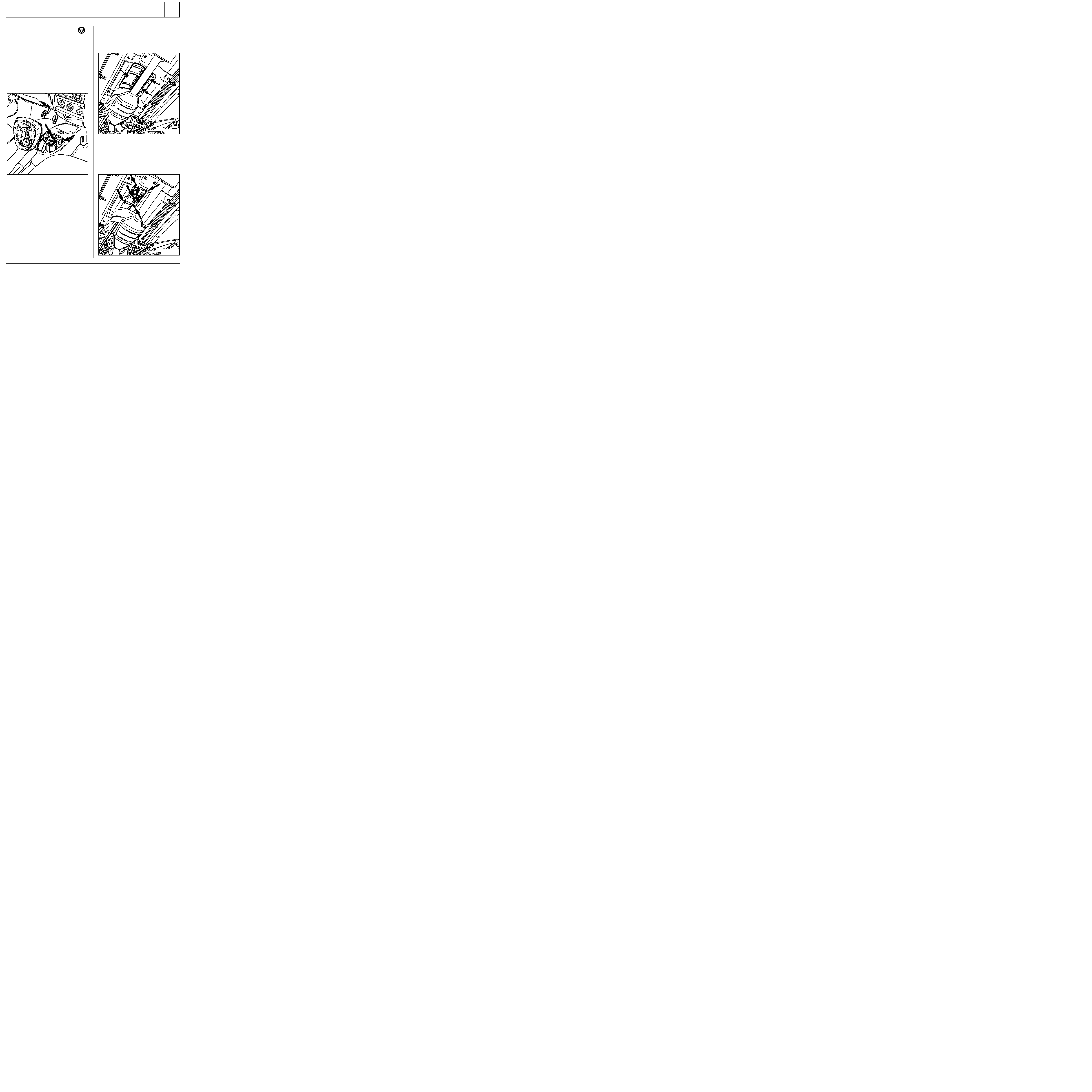
MECHANICAL ELEMENT CONTROLS
External gear control
37
Mounting nut for unit on body
1.5
Linkage mounting clip bolt on clevice
2
Linkage mounting bolt on clevice
3
Linkage - lever mounting nut
3
TIGHTENING TORQUES (in daN.m)
REMOVAL
Disconnect the battery.
In the vehicle, remove the gaiter from the console
and remove the two mounting bolts.
12985R
Under the vehicle:
- release the primary exhaust pipe,
- remove the bolts from the heat shield cover.
12988R
Remove:
- the lever - linkage mounting nut,
- the four nuts mounting the control unit.
12987R
37-24
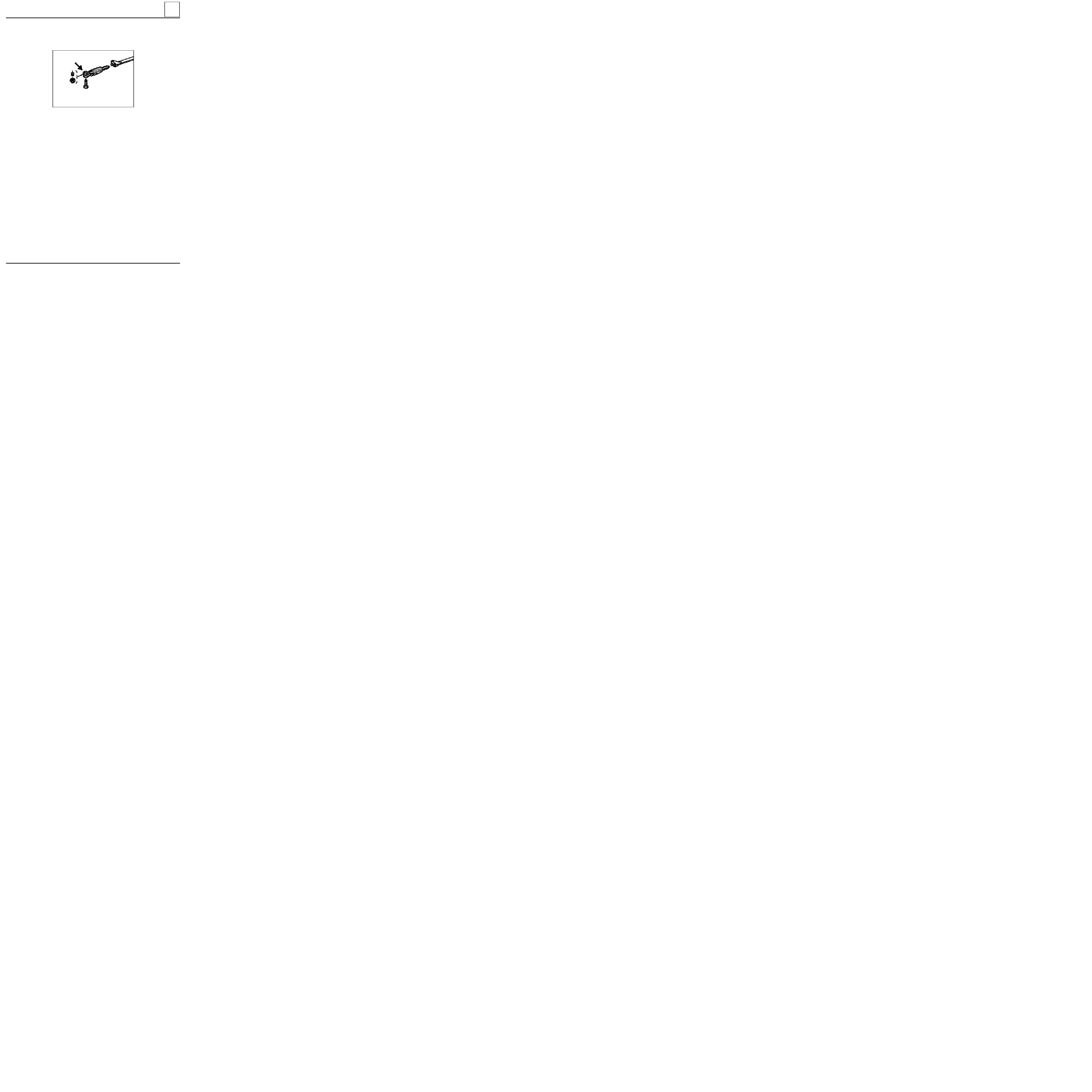
MECHANICAL ELEMENT CONTROLS
External gear control
37
REFITTING
Refitting is the reverse of removal.
Coat the lever joints and the linkage pin with 33
Médium grease.
Ensure the clevice is fitted correctly : offset on
gearbox side.
REMOVAL of the control linkage
After removing the lever - linkage connecting nut,
remove the linkage - selector connecting bolt.
PRG37.6R
37-25
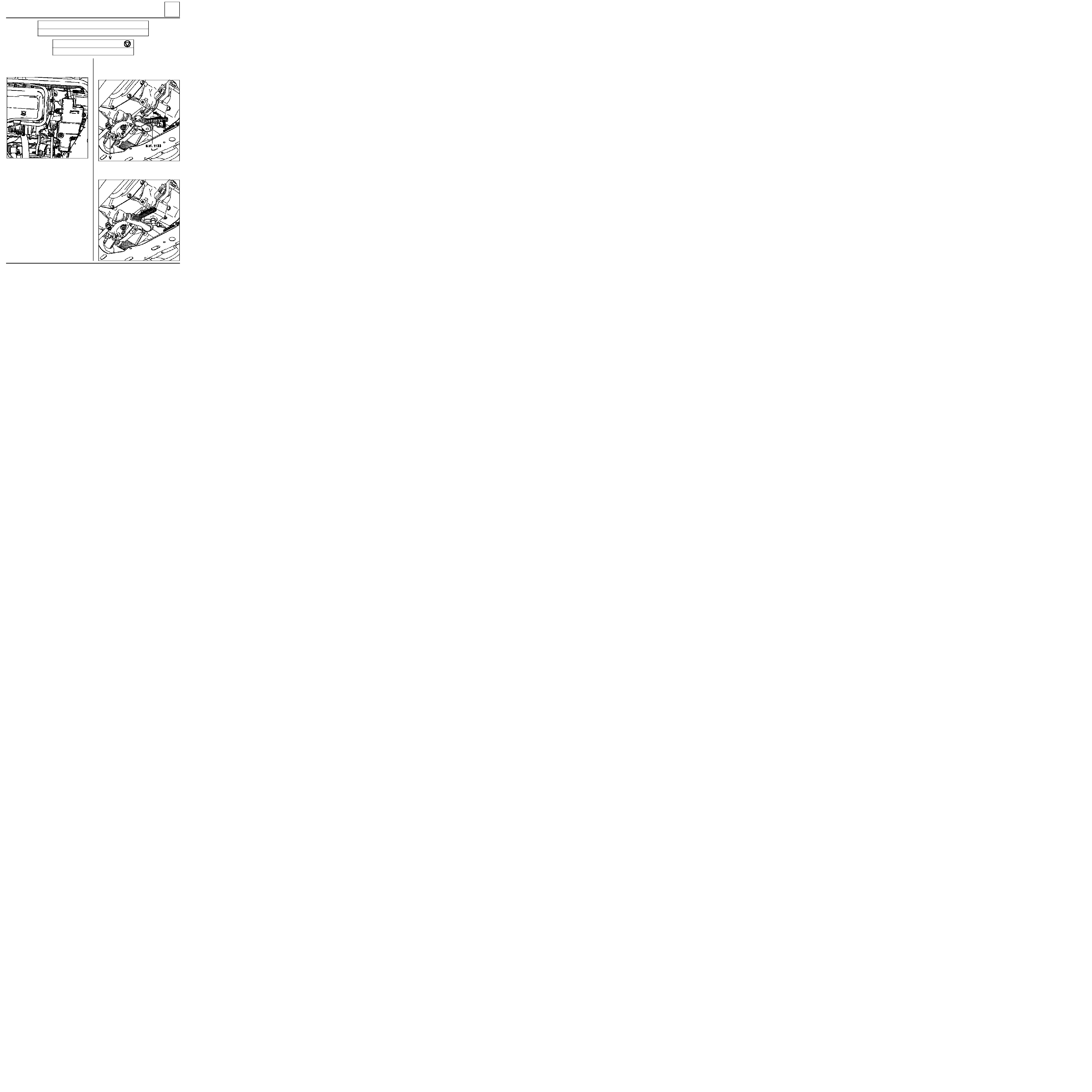
93856-1S
MECHANICAL ELEMENT CONTROLS
External gear control
37
SPECIAL TOOLING REQUIRED
B.Vi. 1133
Shim for locking the gearbox input lever in 1st
Remove the collector.
Engage 1st gear.
TIGHTENING TORQUES (in daN.m)
A D J U S T M E N T
Linkage mounting clip bolt on clevice
2
Slacken bolt (V).
Fit shim B.Vi. 1133 to take up any play.
92450-2R
At the same time pull the end of the shim
downwards and pivot it through approximately
45
°
until it touches the lug on the housing.
92450-3S
37-26
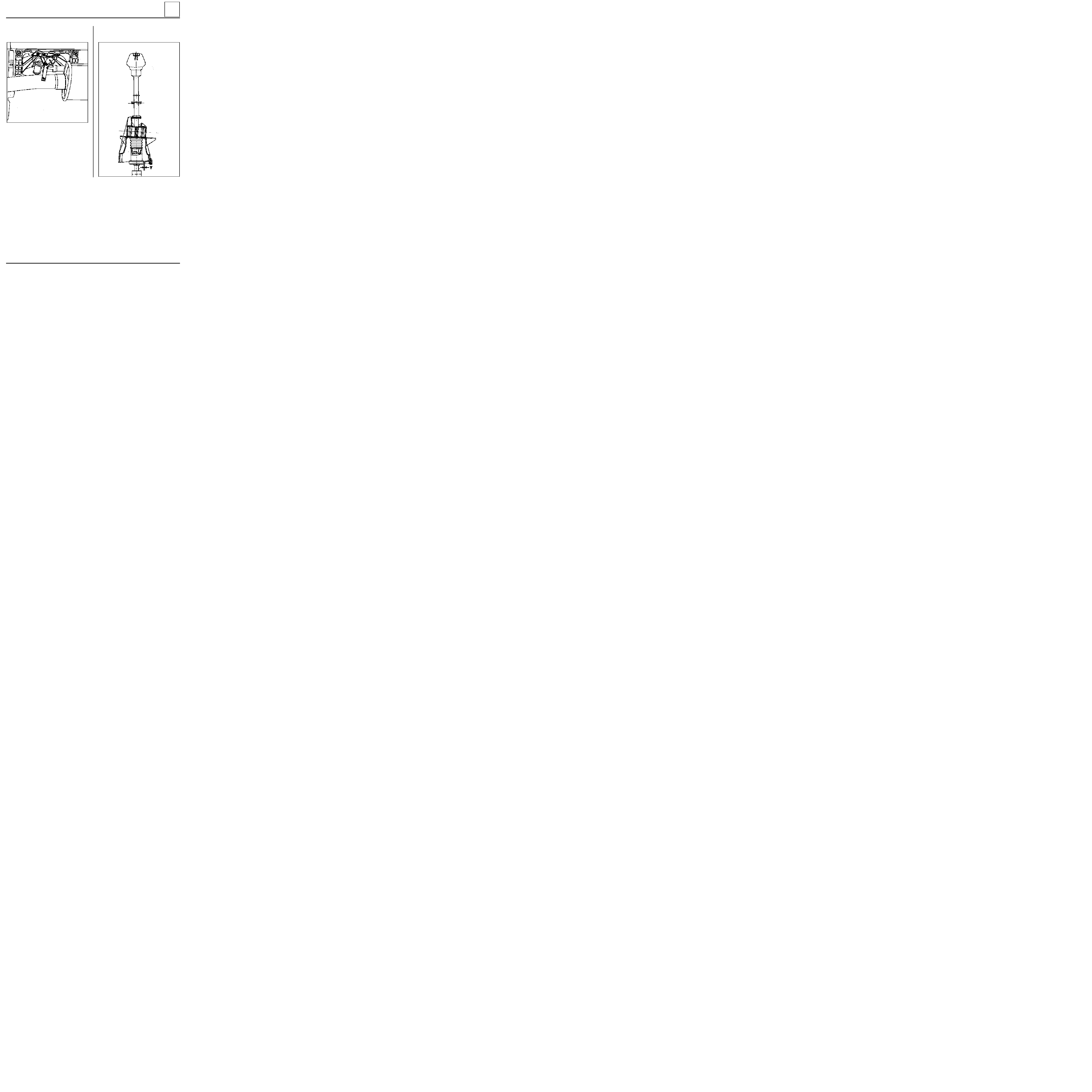
MECHANICAL ELEMENT CONTROLS
External gear control
37
Press the lower lever gate against the gearbox
ramp , inserting a 9 mm shim.
93910S1
In this position, tighten bolt (V).
Check the resulting play ( Y ) which must be
between 7 and 10 mm.
Remove shim B. Vi. 1133.
Check the gears engage correctly.
Refit the collector.
DI3705
37-27

ELECTRONICALLY CONTROLLED HYDRAULIC SYSTEMS
BOSCH ABS
38
This vehicle is fitted with
BOSCH ABS 5.3
of the four channel additional type; the conventional braking
equipment and the ABS equipment are separate.
SPECIAL NOTES
The system comprises four speed sensors. Each hydraulic braking channel is associated with a sensor at each
wheel. The front wheels are therefore regulated separately. The rear wheels however are regulated at the
same time and in the same way according to the select low principle (the first wheel which tends to lock
causes immediate regulation on the complete axle assembly). The compensator fulfils its normal function.
38-1
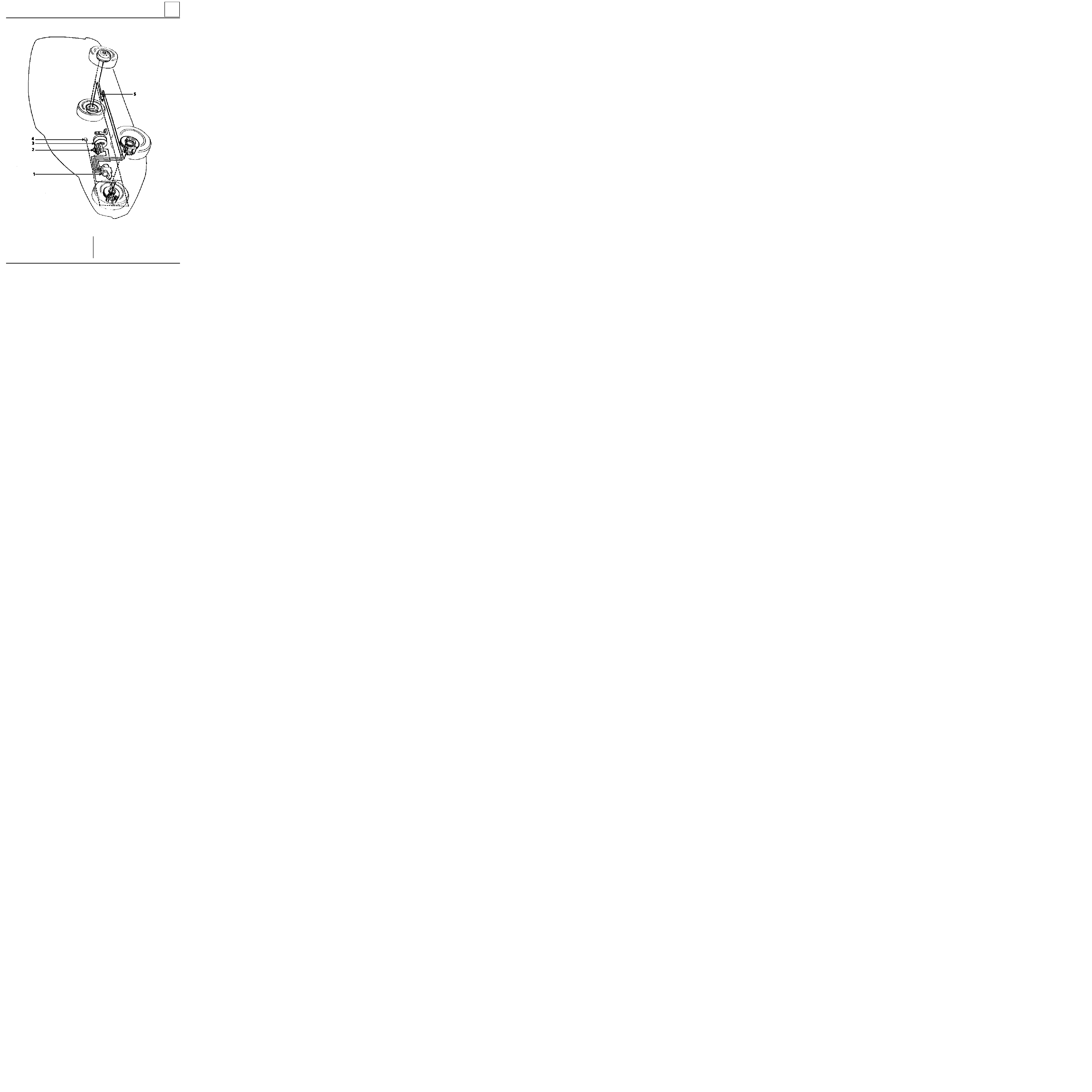
ELECTRONICALLY CONTROLLED HYDRAULIC SYSTEMS
BOSCH ABS
38
PRN3818
LOCATION OF THE BOSCH ABS COMPONENTS
1
Hydraulic assembly
2
Master cylinder
3
Brake servo
4
Brake fluid level warning light
5
Braking compensator
38-2
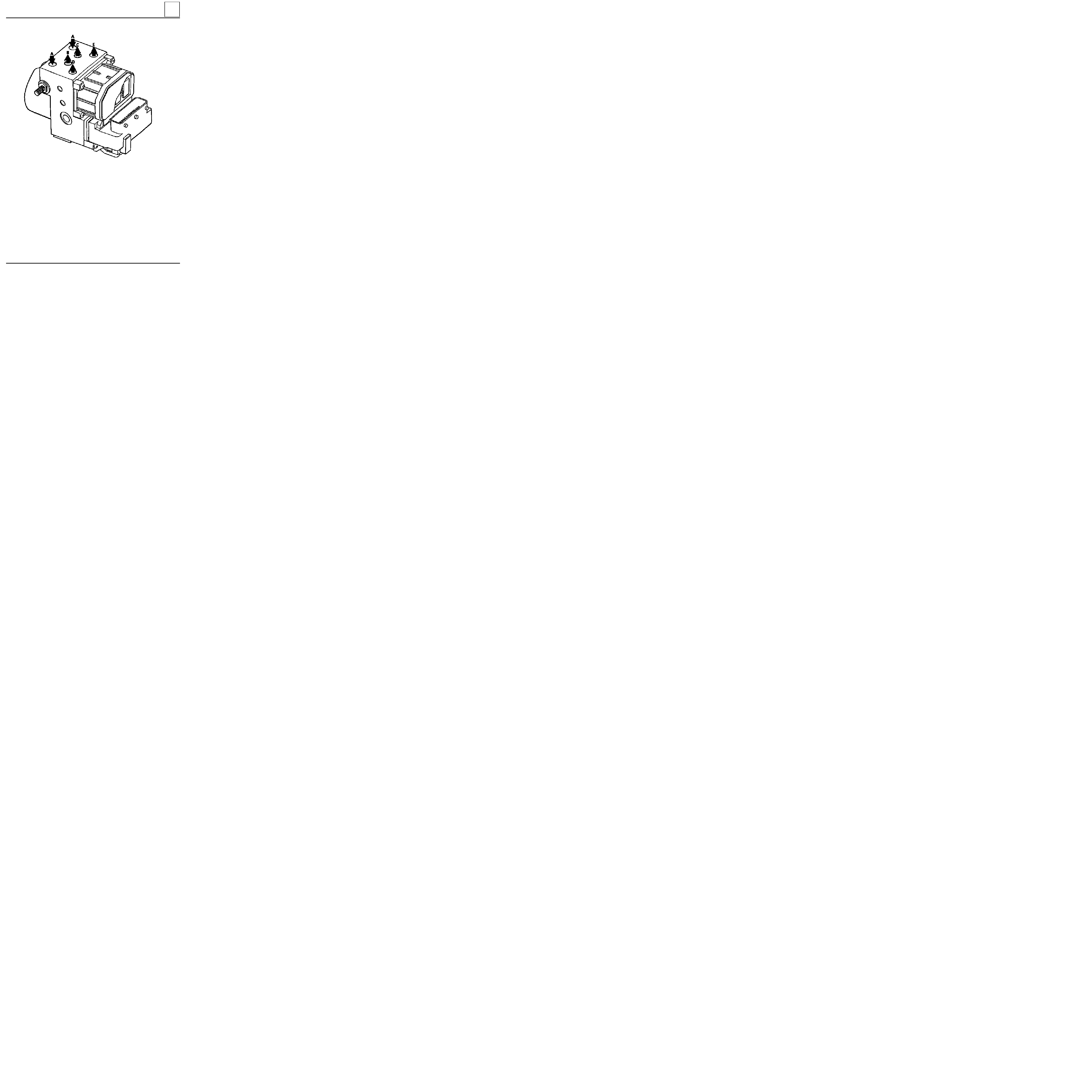
PRN3819
PRESENTATION OF THE HYDRAULIC REGULATION ASSEMBLY
A
Inlet from master cylinder
B
Rear left wheel
C
Rear right wheel
D
Front right wheel
E
Front left wheel
ELECTRONICALLY CONTROLLED HYDRAULIC SYSTEMS
BOSCH ABS
38
38-3
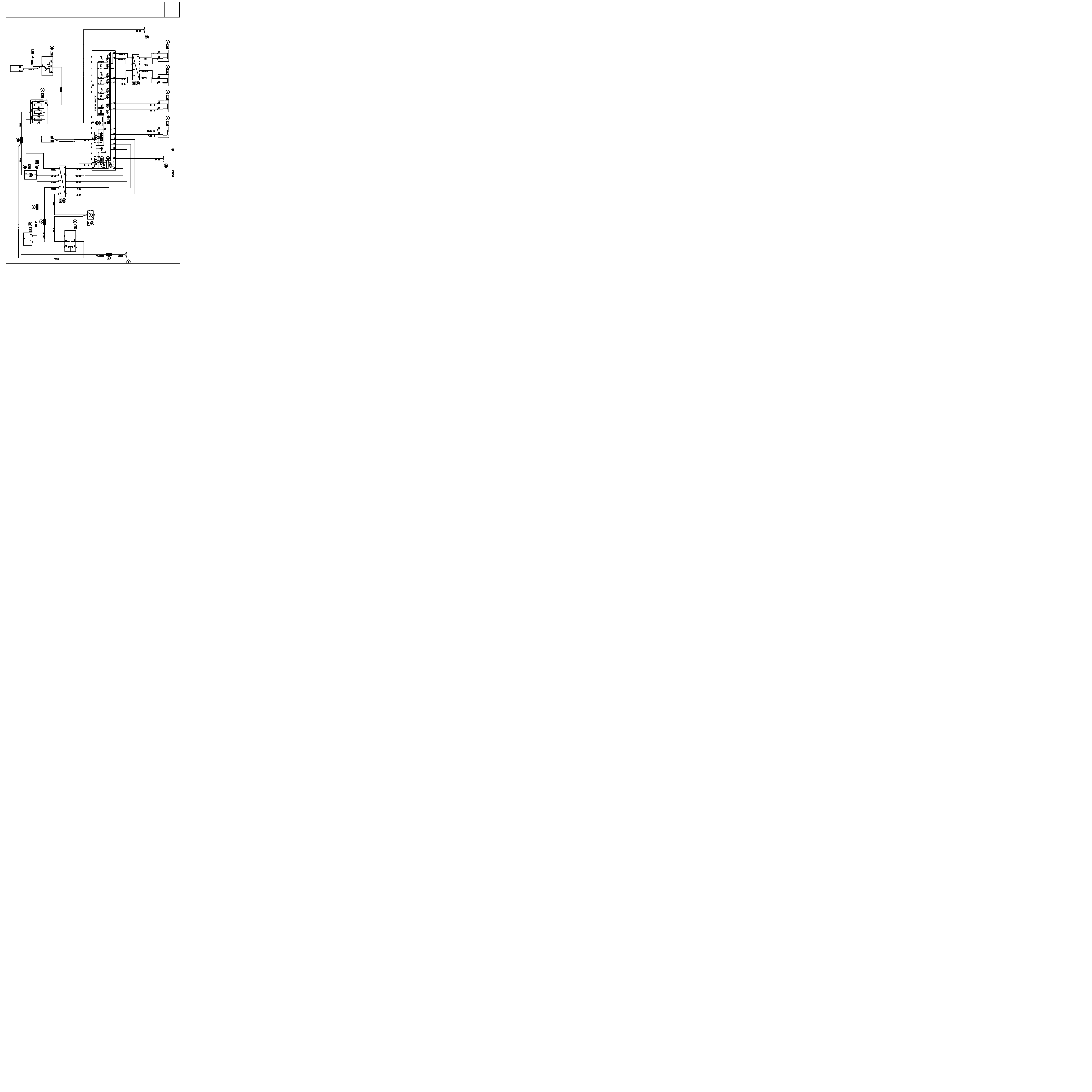
ELECTRONICALLY CONTROLLED HYDRAULIC SYSTEMS
BOSCH ABS
38
PRN3817
WIRING DIAGRAM
38-4

WIRING DIAGRAM KEY
104
Ignition switch
118
ABS
computer
150
Rear right wheel sensor
151
Rear left wheel sensor
152
Front right wheel sensor
153
Front left wheel sensor
160
Stop switch
225
Diagnostic socket
247
Instrument panel
260
Fuse box
777
Power feed fuse board
R2
Dashboard / rear left
R36
ABS / Dashboard
R101
Right hand side member / Right hand
headlight
ELECTRONICALLY CONTROLLED HYDRAULIC SYSTEMS
BOSCH ABS
38
38-5
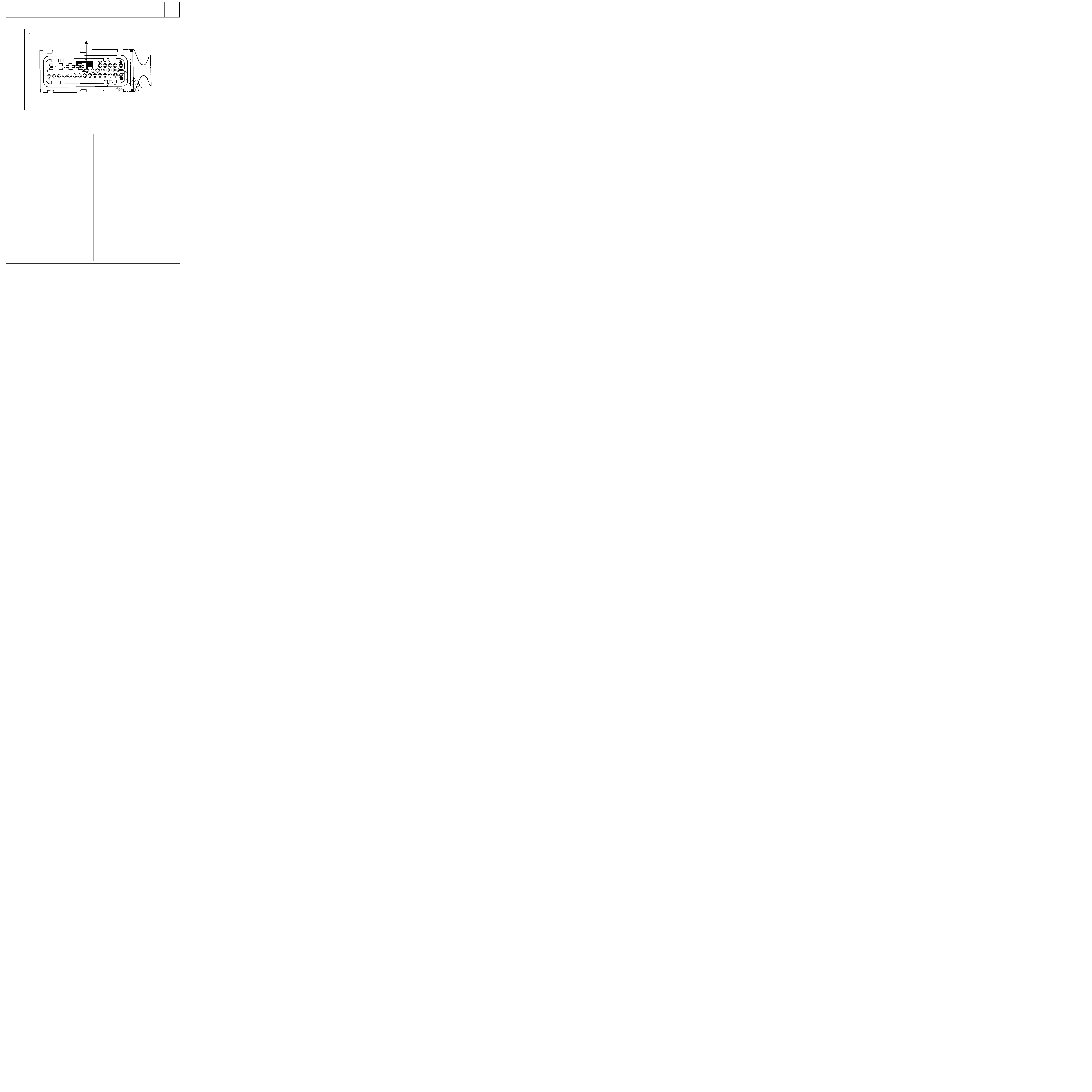
ELECTRONICALLY CONTROLLED HYDRAULIC SYSTEMS
BOSCH ABS
38
PRN3813
31 TRACK CONNECTOR
Track
Description
1
2
3
4
5
6
7
8
9
10
11
12
13
14
Sensor earth - RRH
Sensor information -
RRH
Sensor earth -
FRH
Not connected
Sensor information -
FRH
Sensor earth - FLH
Sensor information - FLH
Sensor earth - RLH
Sensor information - RLH
Not connected
Diagnostic line K
Diagnostic line L
Not connected
Stop lights switch information
A
Micro-spring connecting earth (terminal 19) to pins 20 and 21 (ABS and
NIVOCODE
warning lights) if the
connector is disconnected.
Allocation of connector tracks
Track
Description
15
16
17
18
19
20
21
22
25
26
27
31
+ after ignition computer feed
Pump motor earth
+ BAT
(solenoid valves and pump
motor)
+ BAT
(solenoid valves and pump
motor)
Electronic earth
Not connected
ABS
warning light
Not connected
Not connected
Not connected
Not connected
Not connected
38-6
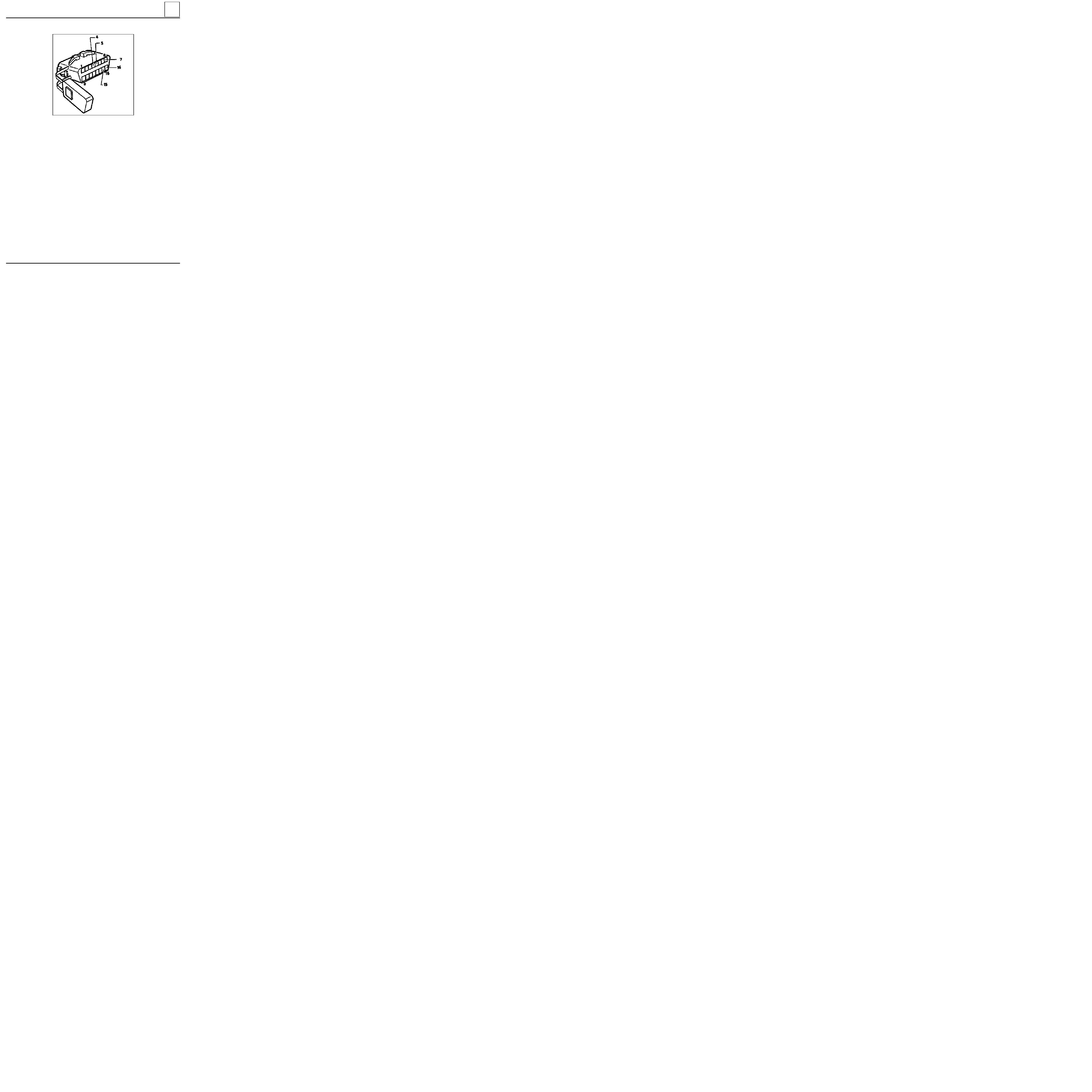
ELECTRONICALLY CONTROLLED HYDRAULIC SYSTEMS
BOSCH ABS
38
DIAGNOSTIC SOCKET
PRN3807
4
Chassis earth
5
Electronic earth
7
Diagnostic line K
15
Diagnostic line L
16
+ battery
38-7
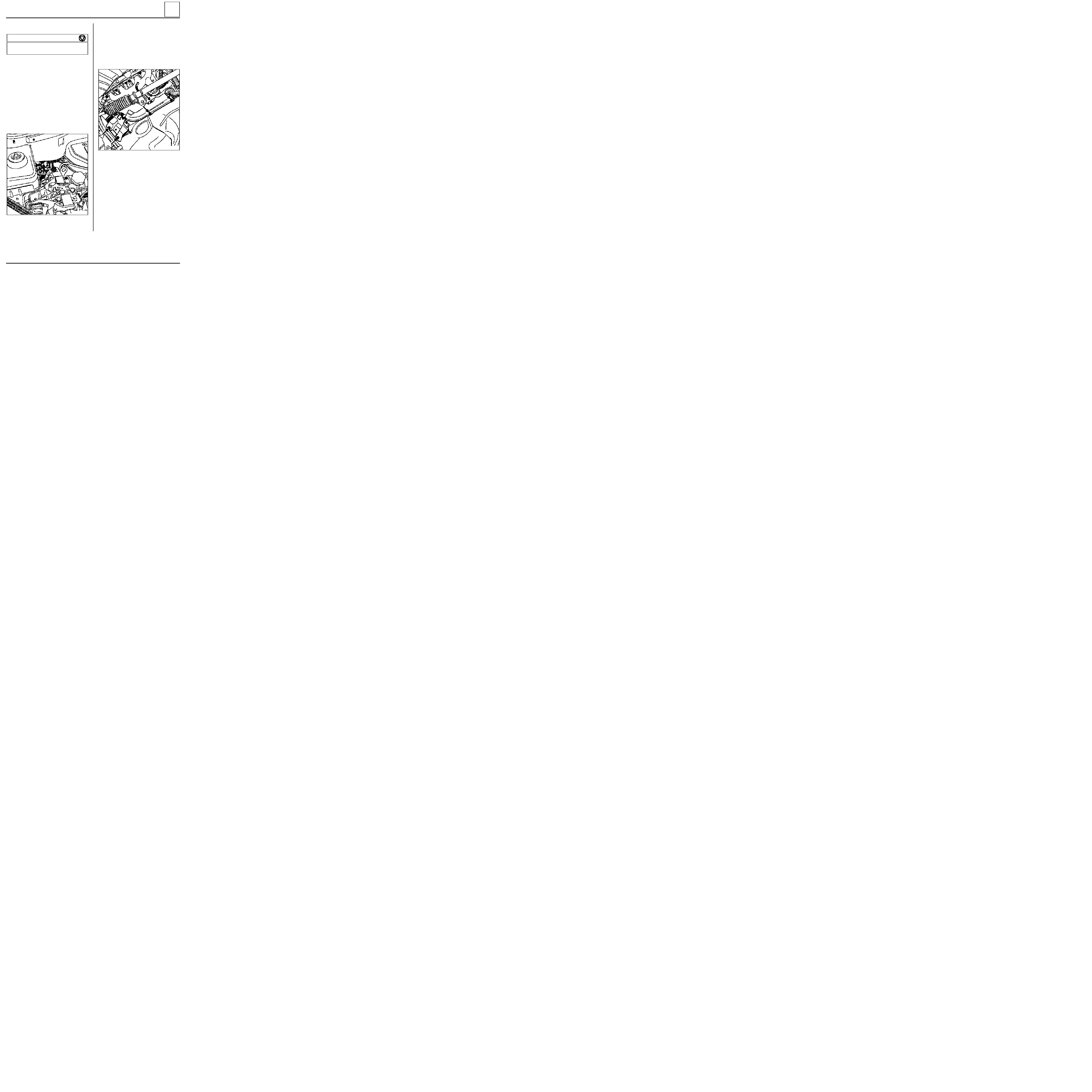
ELECTRONICALLY CONTROLLED HYDRAULIC SYSTEMS
BOSCH ABS
38
13138R
Pipe unions
M10
×
100
1.7
M12
×
100
1.7
TIGHTENING TORQUES (in daN.m)
REMOVAL
Put the vehicle on a two post lift.
Disconnect the battery.
Remove the front right hand wheel.
Fit a pedal press to limit the amount of brake
fluid which will run out.
From above:
Disconnect the computer connector.
Remove the two earth bolts.
Disconnect the six pipes from the hydraulic assem-
bly, marking their position for refitting.
From below:
Remove:
- the exhaust downpipe,
- the exhaust manifold heat shield ( 3 bolts),
- the two lower mounting bolts for the hydraulic
assembly,
HYDRAULIC ASSEMBLY
13139R
-
the hydraulic assembly via the wheel arch.
Remove the upper hydraulic assembly mounting
bolt ( 1 ).
REFITTING
Refitting is the reverse of removal.
NOTE :
the computer must not be removed. If
there is a fault, replace the complete hydraulic as-
sembly.
38-8

ELECTRONICALLY CONTROLLED HYDRAULIC SYSTEMS
BOSCH ABS
38
HYDRAULIC BRAKING TEST
This section describes the test to be carried out using the
XR25
, to check the mounting of the ABS system in
the vehicle and, in particular, the hydraulic circuit.
N O T E :
for this test, two persons are required and the vehicle must be on a two post lift, if possible.
Principle of the test
Put the vehicle on the lift with the wheel to be tested raised. One of the operators must be in the passenger
compartment in the driver’s position with the XR25. Switch the ignition on, vehicle in neutral, in fault finding
mode and press the brake pedal. The second operator must apply a torque to the wheel to try and rotate it.
The operator generates an appropriate command on the XR25 which carries out the following cycle ten
times: alternate decrease then increase in pressure at the wheel to be checked. These actions in the ABS will
be noted at the wheel as ten alternate locking and releasing operations. The jerky movement of the wheel,
noted qualitatively by the operator, signify that the hydraulic circuit for this wheel is correctly connected.
The programme for the XR25 for this sequence is as follows:
-
Cycle on the wheel to be tested:
-
a drop in pressure for 200 ms where the pump starts at the same time,
-
an increase in pressure for 300 ms where the pump starts at the same time (ten cycles are carried out
for the wheel in question).
-
The pressure increases to master cylinder pressure for all four wheels.
-
The hydraulic pump motor stops.
-
The operator releases the brake pedal.
The hydraulic test for the wheel in question is complete - begin the test for the three other wheels.
BLEEDING PROCEDURE
NOTE :
the hydraulic assembly is pre-filled.
This bleeding procedure must be used when one of the following components has been removed:
-
the hydraulic assembly,
-
the master cylinder,
-
the pipework (between the hydraulic assembly and the master cylinder).
1)
Bleed the braking system conventionally using the pedal.
NOTE :
if, after a road test with ABS regulation, the pedal travel is not correct, bleed the hydraulic assembly.
38-9
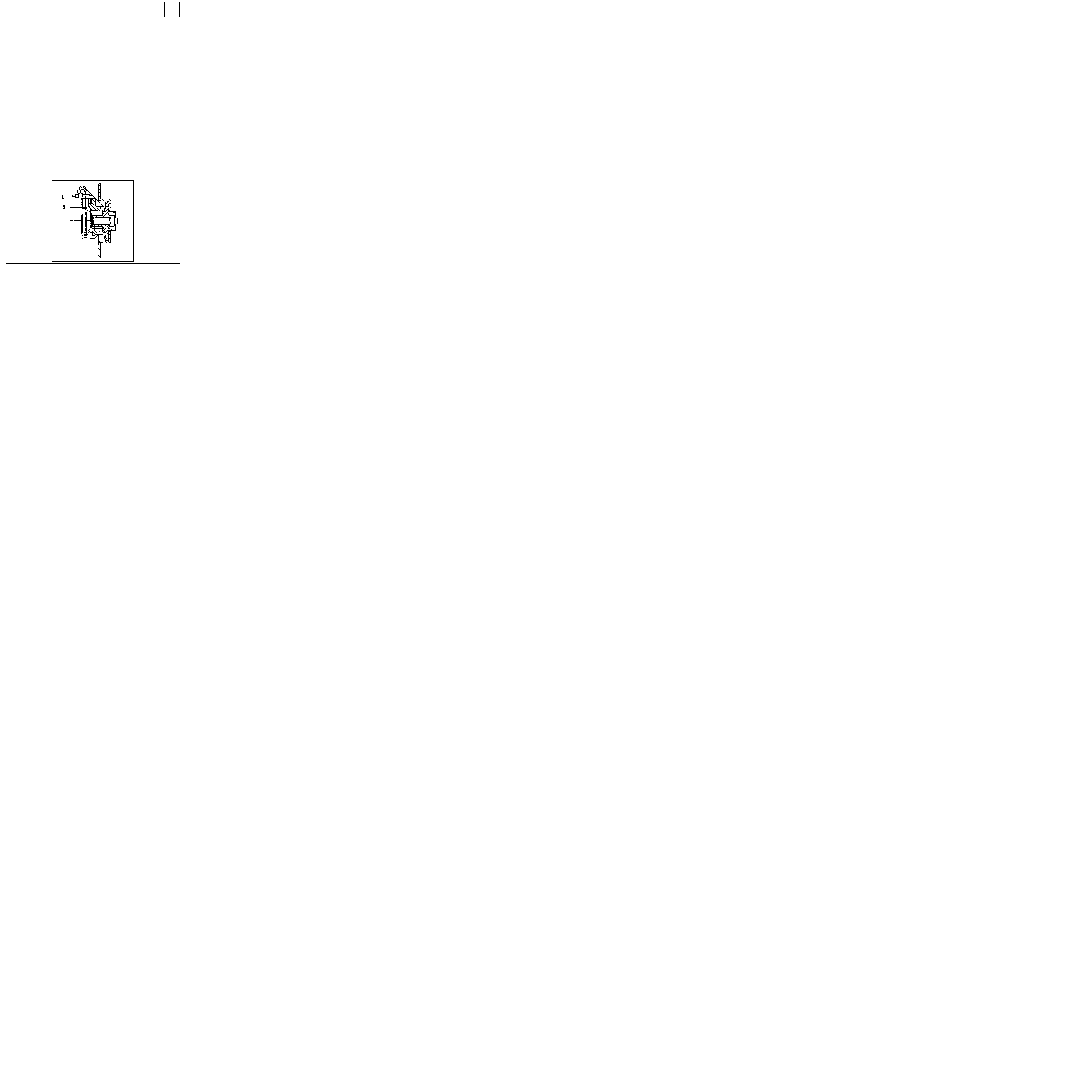
ELECTRONICALLY CONTROLLED HYDRAULIC SYSTEMS
BOSCH ABS
38
2)
Bleeding the hydraulic assembly.
IMPORTANT :
the bleeding order must be observed, beginning with the rear right , then the rear left, front
left
and then front right.
a)
Bleed the rear right brake by bleeding the hydraulic assembly secondary circuit using the XR25:
-
position the bleed container and the hose, open the brake bleed screw,
-
pump the brake pedal (approximately ten times),
-
start the bleed command on the
XR25
,
-
pump the brake pedal during the diagnostic bleed phase,
-
at the end of the bleed cycle on the
XR25
, continue to pump the brake pedal and close the brake
bleed screw.
b)
Carry out the procedure described at a) for the rear left, front left and front right brakes.
c)
Check the pedal travel and if it is incorrect, restart the bleeding procedure.
IMPORTANT :
ensure there is sufficient brake fluid in the reservoir.
CHECKING THE WHEEL SPEED SENSORS
a)
Check the resistance of the sensor connections (from the computer connector to the 2 track speed sensor
connector).
b)
Visually inspect the teeth ( 26 teeth) on the target and if they are faulty, replace the target.
c)
Check the air gap using a set of shims. Only the front sensors can be checked.
PRN3820
Front
: 0.13 < Z < 1.96 mm
38-10
Document Outline
- 30-GENERAL
- 31-FRONT AXLE
- 33-REAR AXLE
- 35-WHEELS AND TYRES
- 36-STEERING ASSEMBLY
- 37-MECHANICAL ELEMENT CONTROLS
- 38-ELECTRONICALLY CONTROLLED HYDRAULIC SYSTEMS
Wyszukiwarka
Podobne podstrony:
MR 325 KANGOO 8
MR 325 KANGOO 0
MR 325 KANGOO 6
MR 325 KANGOO 8
MR 325 KANGOO 0
MR 326 KANGOO 7
MR 326 KANGOO RX4 1
MR 326 KANGOO 6
MR 326 KANGOO 5
MR 326 KANGOO GV 4
więcej podobnych podstron