77 11 198 230
FEBRUARY 1998
Edition Anglaise
Heating and Ventilation
HEATING
Renault 1998
"The repair methods given by the manufacturer in this document are based on the
technical specifications current when it was prepared.
The methods may be modified as a result of changes by the manufacturer in the
production of the various component units and accessories from which his vehicles
are constructed".
All copyrights reserved by Renault.
Copying or translating, in part or in full, of this document or use of the service part
reference numbering system is forbidden without the prior written authority of
Renault.
C
AIR CONDITIONING
CANCELS AND REPLACES:
-
Section n
°
6 of M.R. 325 Part Number: 77 11 194 262 of JULY 1997,
-
Technical Note n
°
2871A Part Number: 77 11 197 147 of DECEMBER 1997.
D7F - E7J - F8Q ENGINES
EXPLODED VIEW
PRO60.5

Contents
Pages
Heating and
Ventilation
Control panel
Control cables
Particle filter
Fan assembly (GMV)
Radiator
Air distribution unit
61-1
61-2
61-3
61-4
61-5
61-6
HEATING
61
General
Fault finding - Introduction
Fault finding - XR25 fiche
Fault finding - Interpretation
of XR25 bargraphs
Fault finding - Customer complaints
Fault finding charts
Fault finding - Associated checks
Wiring diagram
Evaporator
Air blower unit
Compressor
Condenser
Pressure relief valve
Dehydration canister
Connecting pipes
Electrical control
Computer
62
62-1
62-3
62-4
62-6
62-18
62-19
62-43
62-44
62-48
62-50
62-51
62-54
62-55
62-56
62-57
62-60
62-61
AIR CONDITIONING
HEATING
Control panel
61
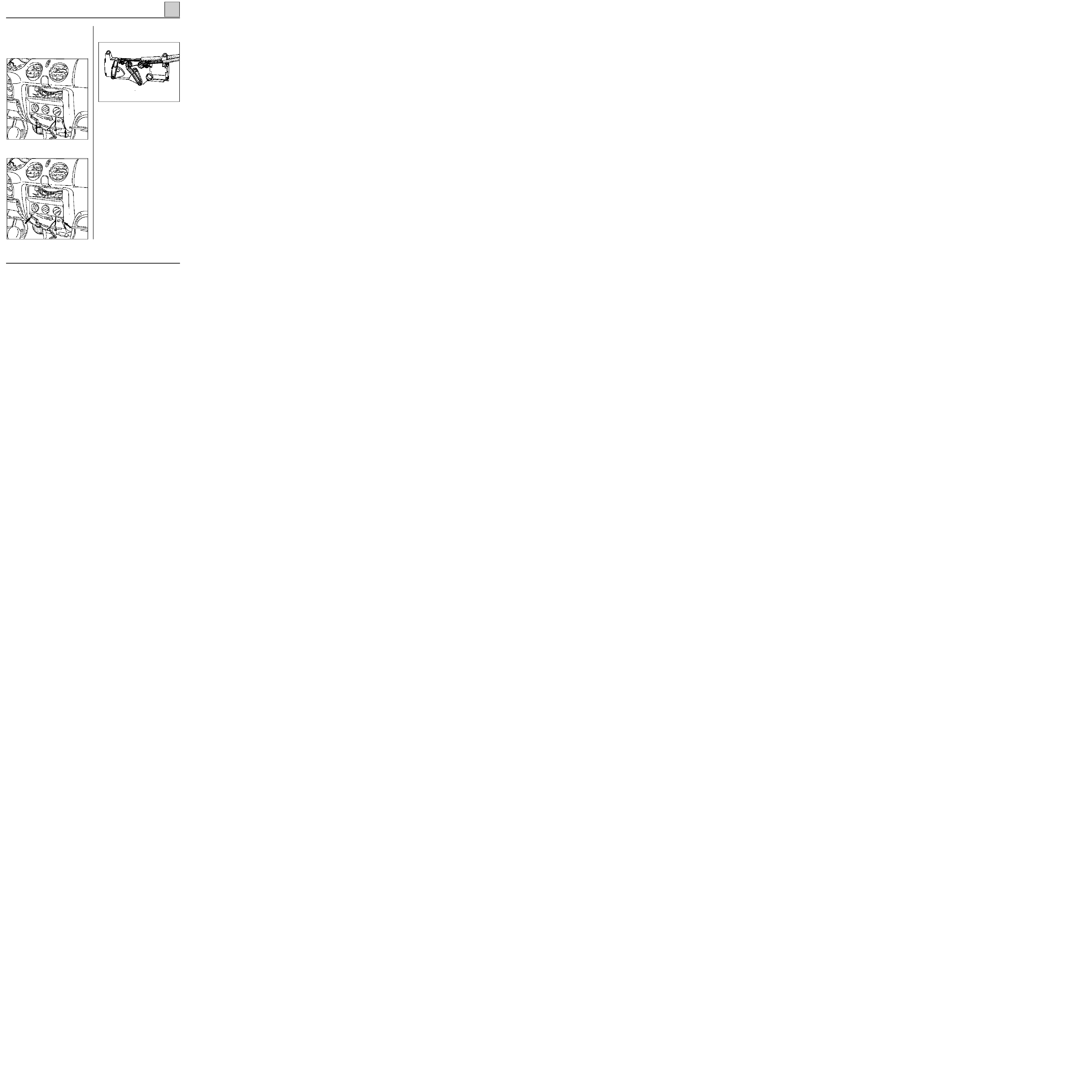
REMOVAL
Disconnect the battery.
Remove:
- the ashtray,
- the mounting screws.
92224S
12963R
- the two screws securing the control panel to
the dashboard.
12963R1
Disconnect :
- control panel connector,
- the control cables for the rotator arms.
REFITTING
Refitting is carried out in reverse order to remo-
val.
Check the adjustment of the air distribution and
air mixing controls (refer to the section on
"Control cables").
61-1

Fit the complete control panel without screwing it
in place.
On the bottom right-hand side
Fit the cable on to the mark.
Place the air distribution control on position
, place the heater control on the maxi-
mum cold position (blue mark) and check that the
flaps are at their end stop.
HEATING
Control cables
61
98815R
92224R1
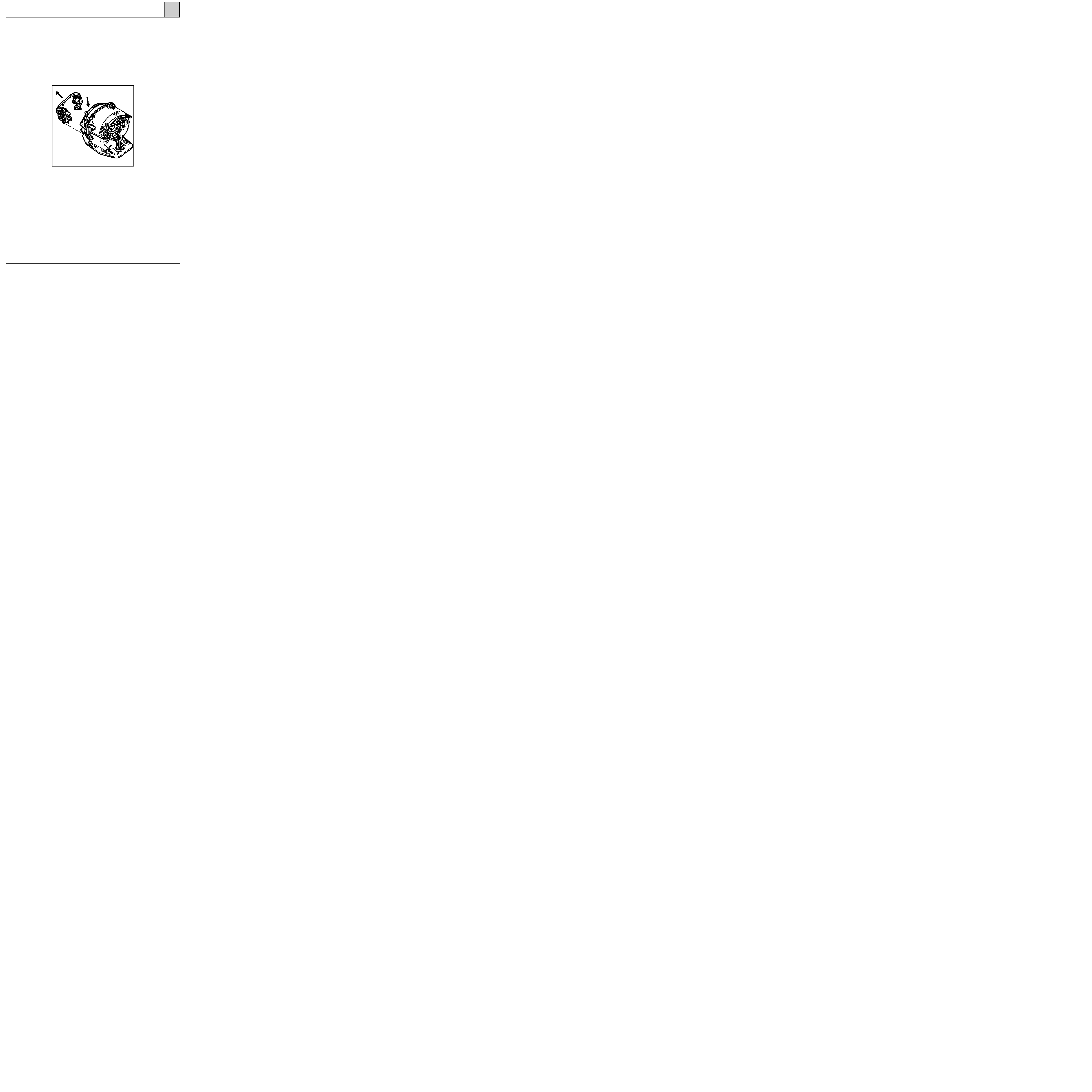
REMOVAL
The control cables can be removed without remo-
ving the dashboard.
Remove :
- the ashtray,
- the control unit.
In the bottom right-hand side of the passenger
compartment
Remove the securing clip (E) (depending on which
cable is to be replaced) :
- from the hot/cold air flap control cable,
or
- from the air distribution cable.
REFITTING
Route the cable through the control panel loca-
tion.
Push back the flap control to prevent the cable
from coming out of its location.
Fit securing clips (E) and (M).
61-2

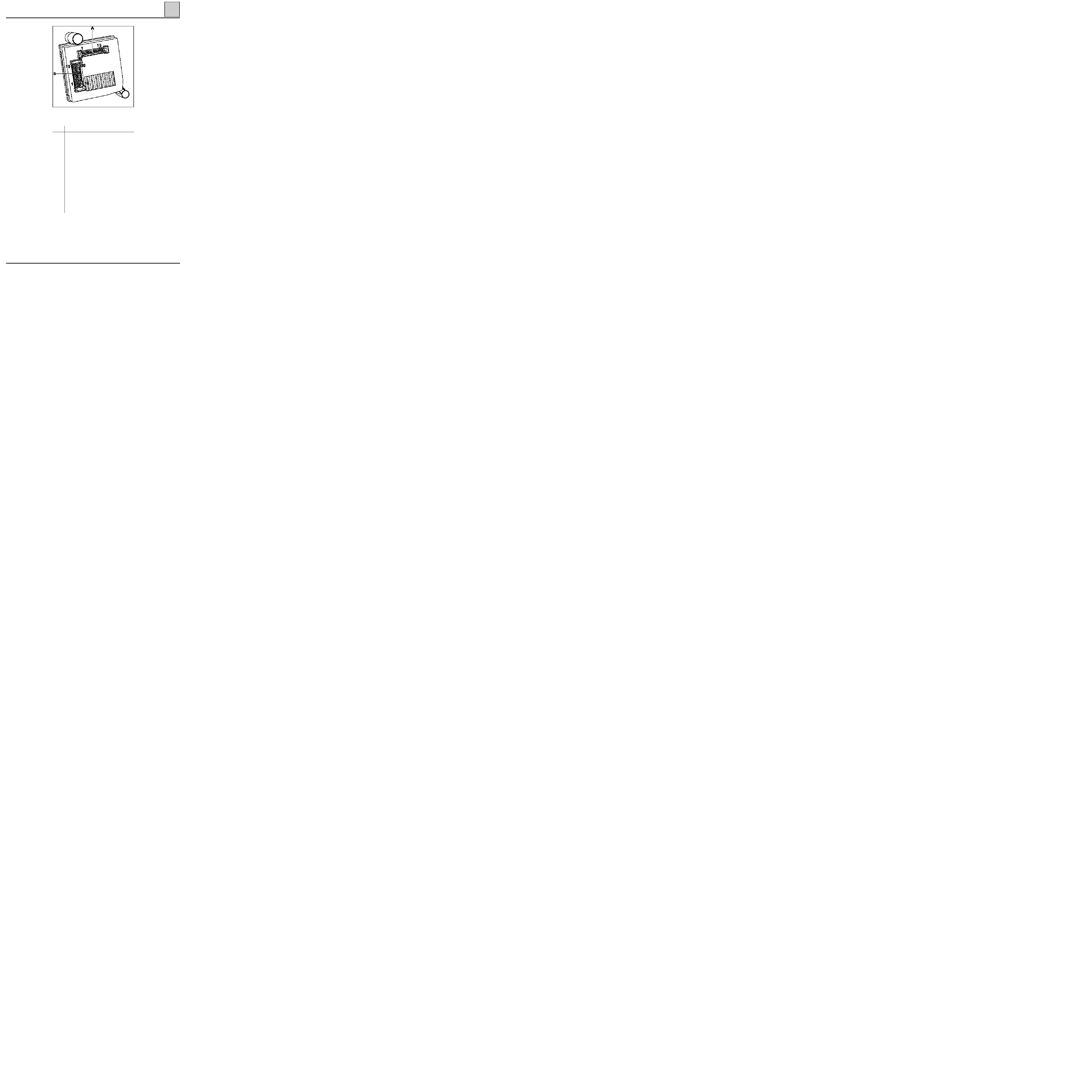
HEATING
Particle filter
61
PRO61.1
REFITTING
Refitting is carried out in reverse order to removal.
Check to make sure that the water drainage channel is correctly fit-
ted in place.
REPLACEMENT
Refer to the Warranty and Servicing book for the vehicle.
REMOVAL
Open the bonnet.
Remove :
- the air intake grille by freeing off the access flap clips,
- the water drainage channel,
- the nut (A) securing the particle filter to the bracket.
61-3
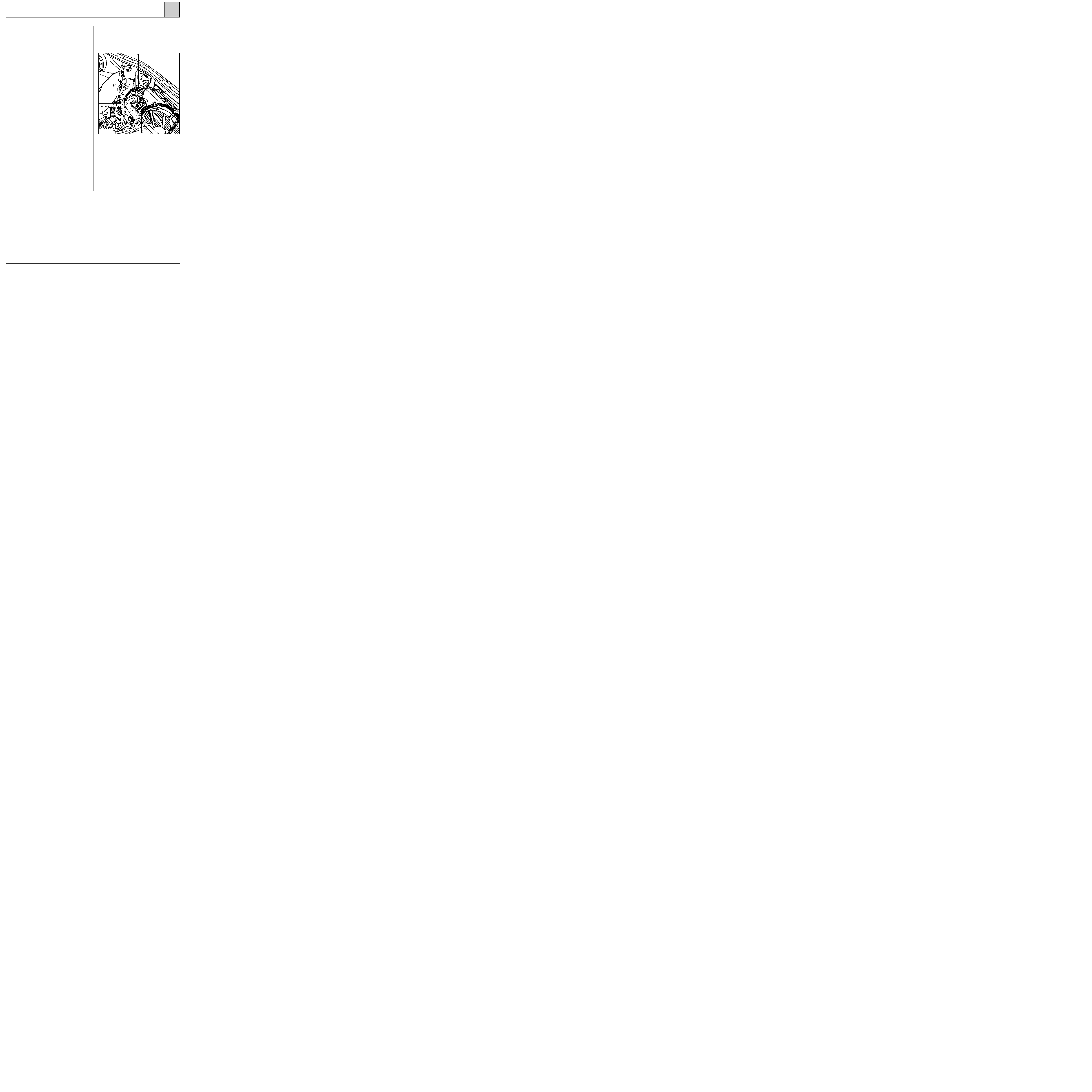
HEATING
Fan assembly (GMV)
61
PRO61.2
Take out the fan assembly through the right-hand
side of the plenum chamber.
REFITTING
Refitting is carried out in reverse order to remo-
val.
Check the condition of the seal.
REMOVAL
Disconnect the battery.
Remove :
- the windscreen wiper arms using tool
Elé. 1294-01
,
- the upper seal for the plenum chamber as well
as the external air intake grille.
Disconnect the feed connector.
Remove the fan assembly mounting bolts.
61-4
HEATING
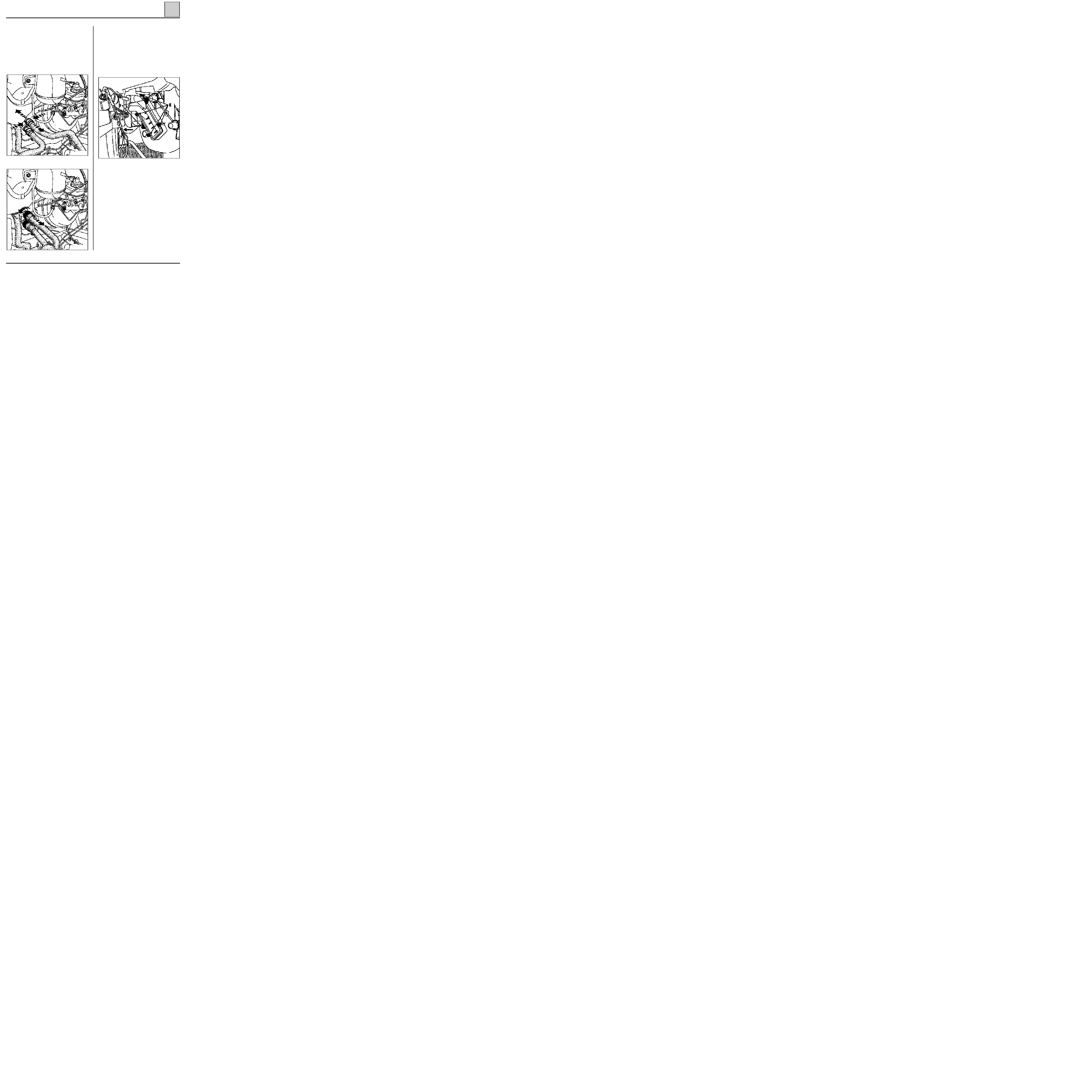
Radiator
61
13084S
98816R
13085S
Other type of quick-release hose clamps.
REMOVAL
The radiator is removed after first removing the
air blower unit, the dashboard and the air distri-
bution unit.
Engine compartment end
Fit a hose clamp and disconnect the quick-release
clamps from the heater hoses.
Fit a deflector and blow out the remaining liquid
using compressed air.
Remove the heater pipe flange bolt on the bul-
khead.
Passenger compartment end
Unclip the four securing clips (E) and take out the
radiator.
REFITTING
Refitting is carried out in reverse order to remo-
val.
Fit two mounting bolts (F) onto the body of the
unit if the clips have broken.
61-5
HEATING
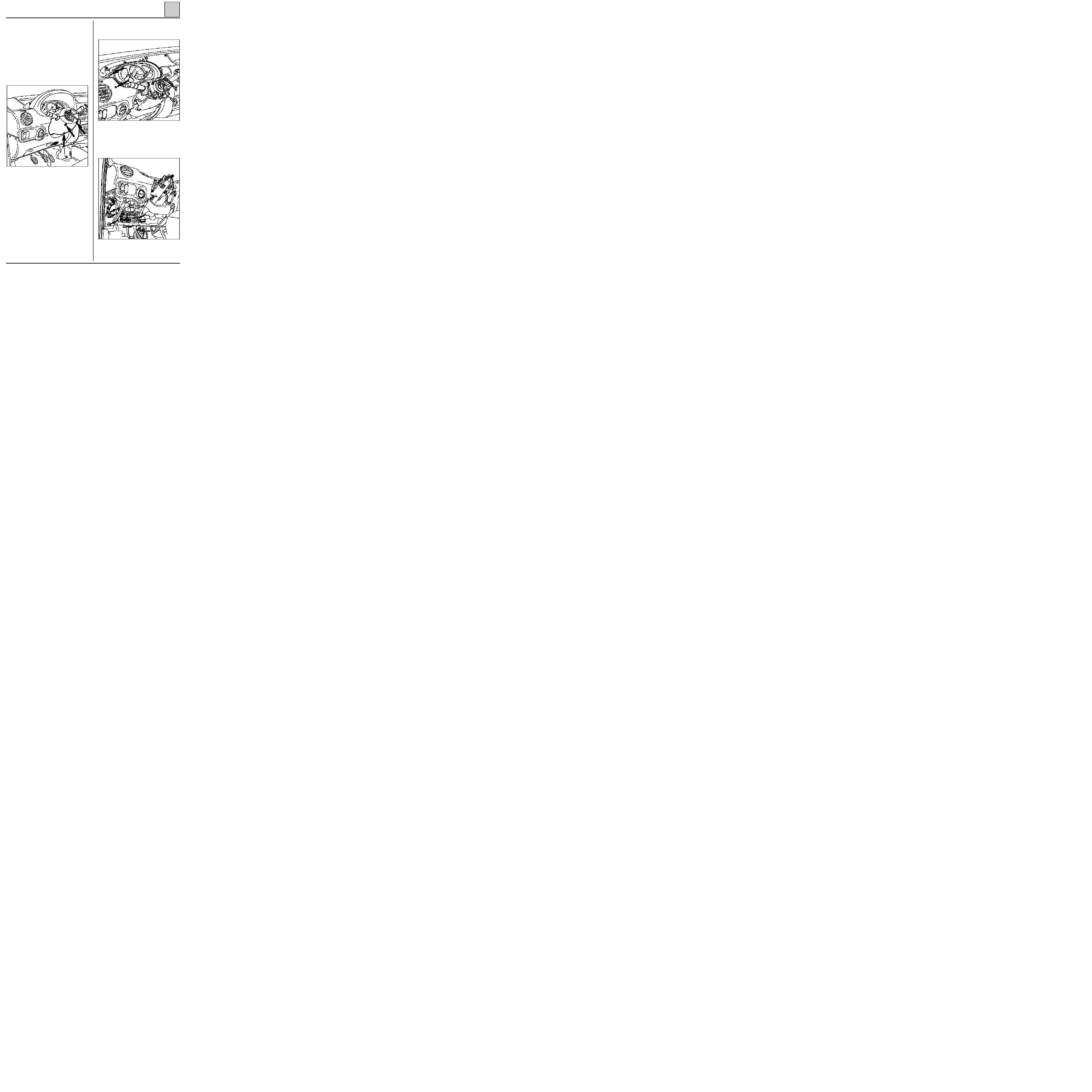
Air distribution unit
61
12969-1R
12965-1R
- the visor and the instrument panel,
- the switch stalk block assembly.
REMOVAL
Disconnect the battery.
Remove :
- the steering wheel bolt,
- the steering wheel after first placing the wheels
in a straight line.
ATTENTION: Follow the recommendations contai-
ned in section 88 relating to the AIR BAG system.
Remove :
- the steering wheel half-shell cowlings,
Using adhesive tape, immobilise the rotor for the
air bag switch.
Remove :
- the ashtray,
- the two screws securing the heater control pa-
nel,
- the fuse holder plate securing screws (five
screws),
- the dashboard mounting nuts.
Unclip the wiring from the dashboard.
Remove the dashboard.
12971R
61-6
HEATING
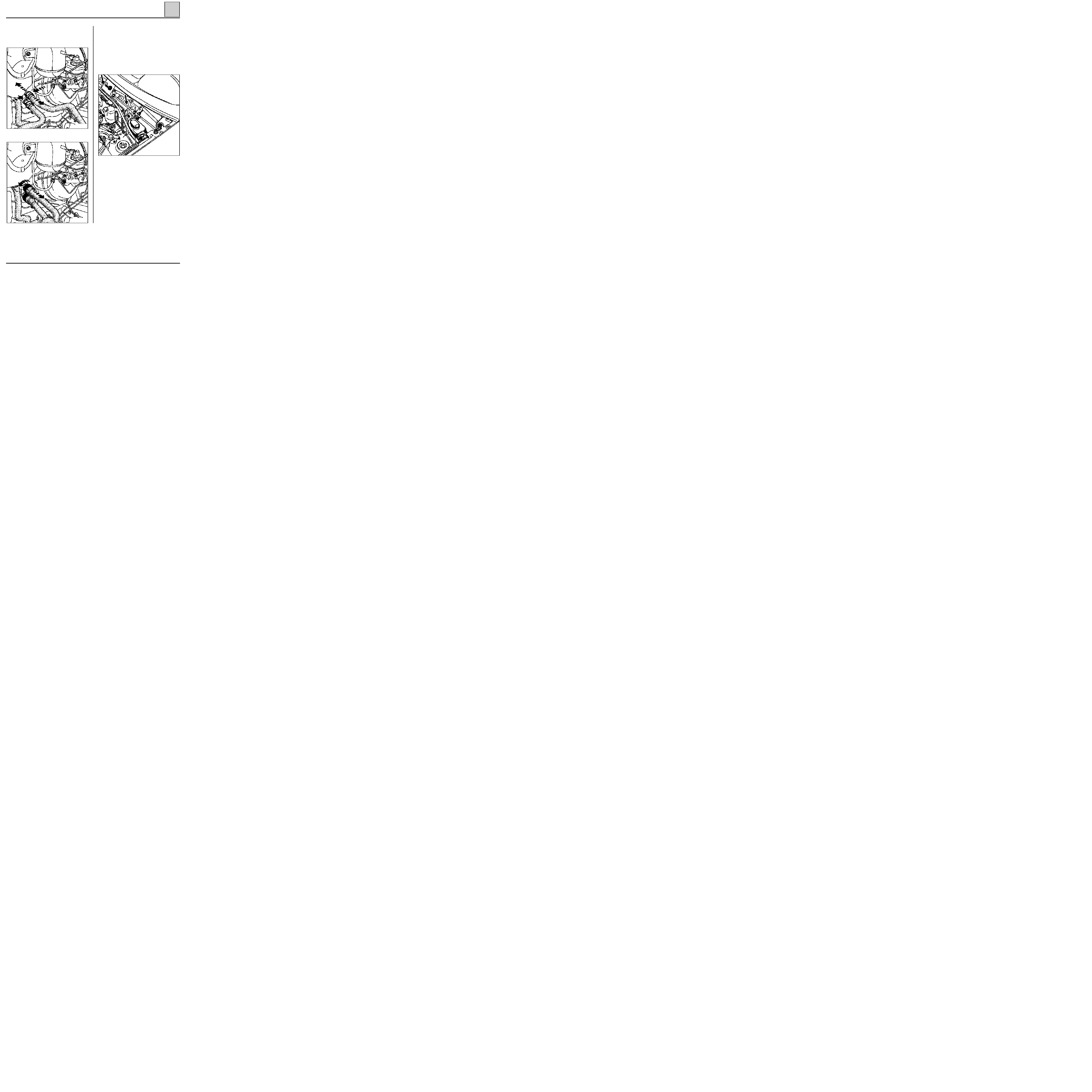
Air distribution unit
61
13084S
13069R3
13085S
Other type of quick-release clamps.
Engine compartment end
Fit a hose clamp and disconnect the quick-release
clamps from the heater hoses.
Fit a deflector and blow out the remaining liquid
using compressed air.
Remove :
- the flange bolt from the heater pipes,
- the windscreen wiper arms using tool
Elé. 1294-01
,
- the upper seal for the plenum chamber as well
as the external air intake grille,
- the blown air unit,
- the air distribution unit mounting bolt.
61-7

HEATING
Air distribution unit
61
PRO61.3
In the passenger compartment
Remove :
- the air distribution unit,
- the heater unit radiator.
REFITTING
Check :
- that the wiring is correctly routed behind the
dashboard,
- that the air ducts are correctly secured to pre-
vent noises developing.
Change the steering wheel bolt (pre-bonded bolt,
tightening torque : 4.5 daN.m).
IMPORTANT :
Before reconnecting the AIR BAG
cushion it is necessary to apply the air bag system
operational check procedure :
• Check that the AIR BAG warning light on the
instrument panel is illuminated when the igni-
tion is switched on.
• Connect an inert ignition unit to the AIR BAG
cushion connector and check that the warning
light extinguishes.
• Switch off the ignition, connect the AIR BAG
cushion in place of the inert ignition unit and
secure the cushion on to the steering wheel.
• Switch on the ignition, check that the air bag
warning light illuminates for three seconds
when the ignition is switched on and then ex-
tinguishes and remains extinguished.
If the warning light does not operate as indicated
above, please consult section 88 of the workshop
repair manual
.
61-8
AIR CONDITIONING
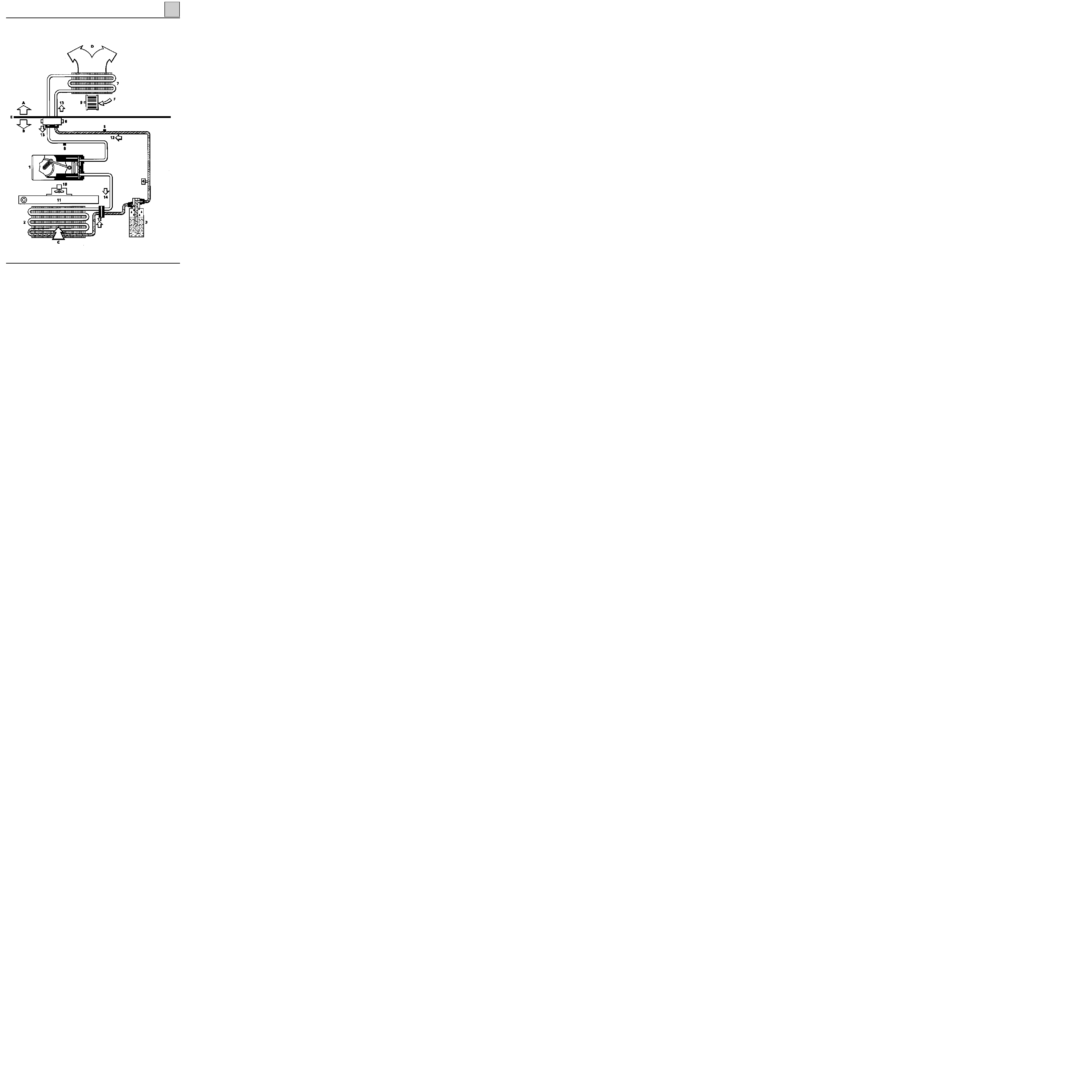
General
62
91096-3R1
62-1

AIR CONDITIONING
General
62
A
Passenger compartment
B
Engine compartment
C
Exterior air
D
To air mixing unit
E
Scuttle panel grille
F
Exterior or recirculated air
1
Compressor with variable capacity
2
Condenser
3
Dehydration canister
4
Pressure sensor
5
High pressure valve
6
Pressure relief valve
7
Evaporator
8
Low pressure valve
9
Heating/ventilation fan
10 Cooling fan
11 Engine radiator
12 High pressure fluid
13 Low pressure vapour
14 High pressure vapour
Consumables:
-
Compressor oil
SANDEN SP 10: 135 cm
3
±
15
-
Coolant
R134a: 650 g
±
35
-
Compressor
SANDEN SD 7V 16
62-2

c11010.0
AIR CONDITIONING
Fault finding - Introduction
62
KANGOO
ALL TYPES
ESTABLISHING XR25 / HEATING-VENTILATION CONTROL UNIT DIALOGUE
-
Connect the XR25 to the diagnostic socket.
-
ISO selector on S8
-
Enter
D17
n.61
PRECAUTION :
When carrying out checks using a multimeter, avoid using a contact tip on the connectors the size of which
could damage the clips and result in poor contact.
ERASING THE MEMORY:
After repairing the air conditioning system, enter G0** on the XR25 keypad to erase the fault stored.
62-3
c11010.0
AIR CONDITIONING
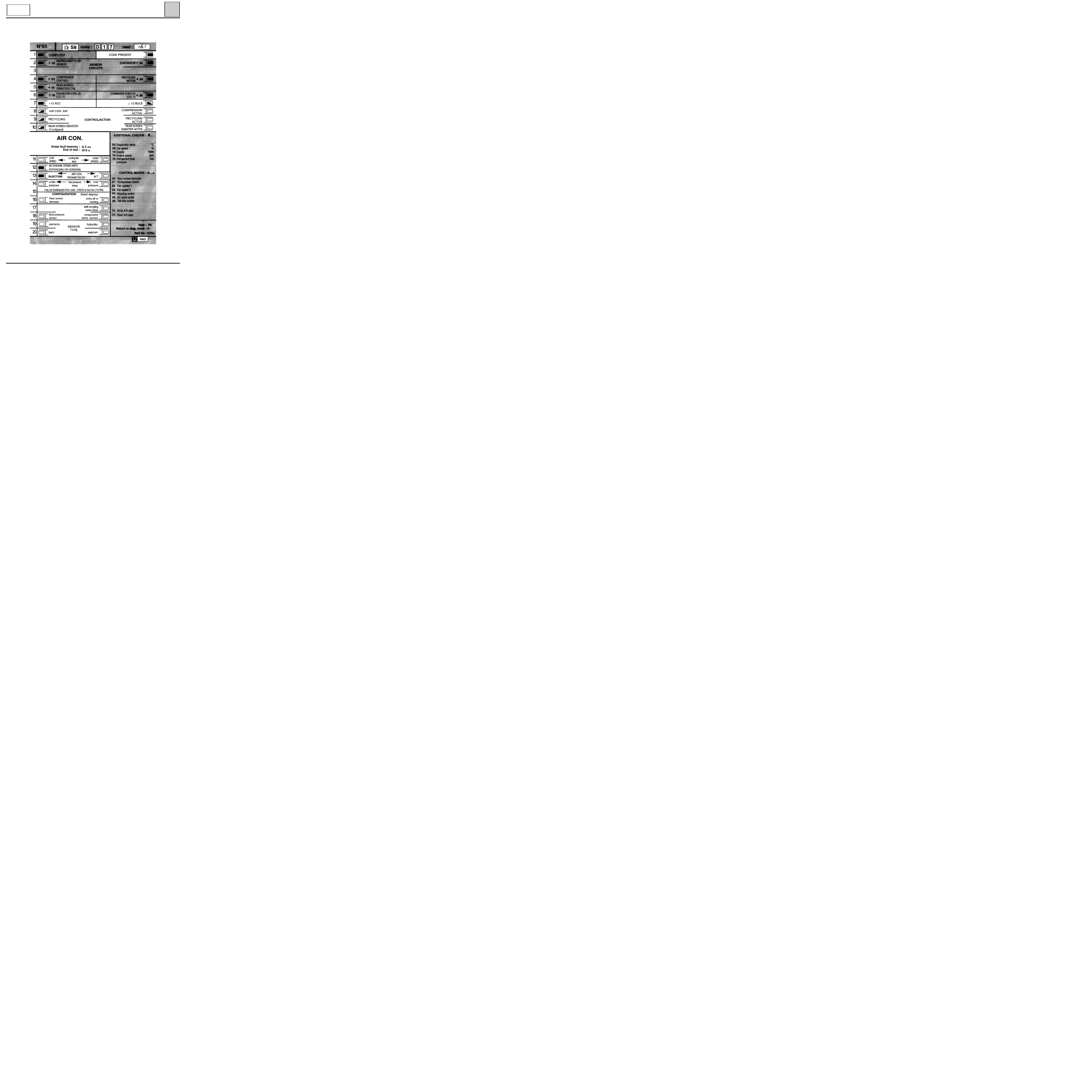
Fault finding - XR25 fiche
62
KANGOO
ALL TYPES
PRESENTATION OF XR25 FICHE N
°
61
FI21761
62-4
c11010.0
AIR CONDITIONING
Fault finding - XR25 fiche
62
KANGOO
ALL TYPES
REPRESENTATION OF BARGRAPHS
REPRESENTATION OF FAULTS (always on a coloured background)
If illuminated, this indicates a fault on the component in question, the associated text defines
the fault.
REPRESENTATION OF STATUS (always on a white background)
Illuminates when dialogue is established with the component computer, if it remains
extinguished:
-
the code does not exist,
-
there is an equipment, computer or line fault.
Engine stopped, ignition on, no operator action
The status bargraphs on the fiche are represented as they should appear with the engine stopped, ignition
on and no operator action.
- If on the fiche, the bargraph is represented
the XR25 should display
- If on the fiche, the bargraph is represented
the XR25 should display
- If on the fiche, the bargraph is represented
the XR25 should display
either
or
Engine running
Extinguished when the function or condition described on the fiche is no longer carried out.
Illuminated when the function or condition described on the fiche is carried out.
62-5
c11010.0
AIR CONDITIONING
Fault finding - Interpretation of XR25 bargraphs
62
KANGOO
ALL TYPES
Enter G0** on the XR25.
Check that the system operates correctly.
AFTER
REPAIR
Left-hand bargraph 1 illuminated
COMPUTER FAULT
1
None.
NOTES
Fiche n
°
61
Change the air conditioning control unit.
62-6

c11010.0
AIR CONDITIONING
Fault finding - Interpretation of XR25 bargraphs
62
KANGOO
ALL TYPES
You may begin the fault finding procedure.
AFTER
REPAIR
Right-hand bargraph 1 extinguished
XR25 / CONTROL UNIT COMMUNICATION
1
None.
NOTES
Fiche n
°
61
Before establishing communication between the XR25 and the control unit, check that you have switched
on the ignition.
Ensure that the XR25 is not the cause of the fault by trying to communicate with a computer on another
vehicle.
Check that the ISO interface is in position S8 and that you are using the latest version of the XR25 cassette
and the correct access code (D 17).
Check the battery voltage (U > 10.5 volts). Recharge the battery if necessary.
Check that the control unit connectors are engaged correctly.
Check that the air conditioning control unit is supplied correctly:
- earth on track 4 of the red 15-way connector
-+ after ignition on track 1 of the blue 30-way connector
-+ after ignition on track 6 of the red 15-way connector
-+ fuse board on track 5 of the red 15-way connector
Check that the diagnostic socket is supplied correctly:
track K
track 6
of the air conditioning control unit
track L
track 3
blue 30-way connector
If there is still no dialogue between the XR25 and the control unit, change the air conditioning control
unit.
62-7

c11010.0
AIR CONDITIONING
Fault finding - Interpretation of XR25 bargraphs
62
KANGOO
ALL TYPES
Enter G0** on the XR25.
Check that the system operates correctly.
AFTER
REPAIR
Left-hand bargraph 2 illuminated
COOLANT SENSOR
XR 25 assistance:
*02
: 2 def = low level
1 def = high level
2
None.
NOTES
Fiche n
°
61
Low level
Check the continuity and insulation from earth of the electrical wiring between tracks A, B and C of the
sensor and tracks 9, 10 and 11 of the air conditioning control unit 30-way connector (sensor supplied with
5 V).
Repair the faulty electrical wiring.
Connect the XR25 and enter # 16. Measure the coolant pressure. The low pressure should be less than or
equal to 2 bars.
Is it correct?
Change the coolant pressure sensor.
YES
NO
Top up the coolant.
Check that the coolant sensor connector is correctly engaged.
Engage the connector correctly if necessary.
62-8
c11010.0
AIR CONDITIONING
Fault finding - Interpretation of XR25 bargraphs
62
KANGOO
ALL TYPES
Enter G0** on the XR25.
Check that the system operates correctly.
AFTER
REPAIR
2
High level
Change the coolant pressure sensor.
YES
NO
Top up the coolant.
CONT
Check that the coolant sensor connector is correctly engaged.
Engage the connector correctly if necessary.
Check the condition of the electrical wiring between tracks A, B and C of the sensor and tracks 9, 10 and
11
of the air conditioning control unit 30-way connector (sensor supplied with 5 V).
Repair the faulty electrical wiring.
Connect the XR25 and enter # 16. Measure the coolant pressure. The high pressure should be less than or
equal to 28 bars.
Is it correct?
62-9

c11010.0
AIR CONDITIONING
Fault finding - Interpretation of XR25 bargraphs
62
KANGOO
ALL TYPES
Enter G0** on the XR25.
Check that the system operates correctly.
AFTER
REPAIR
Left-hand bargraph 4 illuminated
COMPRESSOR CONTROL
XR25 assistance :
C.O.
open circuit
C.C.1
short circuit to 12 volts
4
Before any removal, enter G0** on the XR25 and reinitialise the system.
NOTES
Fiche n
°
61
YES
YES
Change the clutch.
Refer to Left-hand bargraph 4 illuminated, CONT 1.
NO
NO
Top up the coolant circuit.
Repair the circuit if necessary.
If left-hand bargraph 4 remains permanently illuminated, change
the clutch.
If left-hand bargraph 4 still remains permanently illuminated,
change the compressor.
Using the XR25, check the pressure of the circuit (# 16).
At an ambient temperature of approximately 20
°
C
, a pressure of between 2 and
28 bars
should be measured.
Is the pressure between these values?
Enter G21* on the XR25 to control the compressor.
Does the compressor cut in?
62-10
c11010.0
AIR CONDITIONING
Fault finding - Interpretation of XR25 bargraphs
62
KANGOO
ALL TYPES
Enter G0** on the XR25.
Check that the system operates correctly.
AFTER
REPAIR
4
CONT 1
YES
NO
Check that 12 volts is present on track 1 of the clutch connector.
Is 12 volts present?
Check the condition of the compressor earth.
Is the compressor earth in good condition?
YES
Check the continuity and absence of short circuits of the electrical
wiring between the clutch and the compressor.
If the electrical wiring is faulty, repair it.
If the electrical wiring is in good condition, change the compressor.
NO
Repair the compressor earth.
Check the continuity and absence of short circuits of the electrical wiring
between track 1 of the clutch and tracks 2 and 17 of the air conditioning control
unit 30-way connector.
Repair the electrical wiring if necessary.
For petrol vehicles:
Use the XR25 fiche which corresponds to the vehicle.
With the engine running, operate the AC then check on the XR25 fiche whether
the "Compression authorised or prohibited" status bargraph is illuminated.
Is the bargraph illuminated?
YES
Check and repair the electrical wiring.
NO
Refer to Left-hand bargraph 4 illuminated, cont 2.
62-11

c11010.0
AIR CONDITIONING
Fault finding - Interpretation of XR25 bargraphs
62
KANGOO
ALL TYPES
Enter G0** on the XR25.
Check that the system operates correctly.
AFTER
REPAIR
4
CONT 2
YES
NO
For petrol vehicles:
Use the XR25 injection fiche which corresponds to the vehicle.
With the engine running, operate the AC then check on the XR25 fiche whether the " AC authorisation"
status bargraph is illuminated.
Is the bargraph illuminated?
There is a problem at the injection end.
Refer to the injection fault finding procedure which corresponds to the vehicle.
Check the continuity and absence of short circuits of the electrical wiring.
Repair if necessary.
Check that 12 volts is present on tracks 2 and 17 of the air conditioning control
unit 30-way connector.
Is 12 volts present?
YES
There is a problem at the injection end.
Refer to the injection fault finding procedure which corresponds to
the vehicle.
NO
Check whether the evaporator temperature sensor is in place.
Check its resistance: disconnect the evaporator temperature sensor
and measure the resistance at its terminals. The resistance measured
should be between 90 ohms and 13.7 kohms.
If the evaporator temperature sensor is in good condition, change
the air conditioning control unit.
If the evaporator temperature sensor is not in good condition,
change it.
62-12
Check the continuity and insulation from earth and from 12 volts of the electrical wiring between tracks:
air recirculation
B2
27
air conditioning control unit
motor connector
B3
26
blue 30-way connector
Repair the faulty electrical wiring.
Check the condition of the electrical wiring between tracks:
control
A2
3
air conditioning control unit
panel
red 15-way connector
Repair if necessary.
c11010.0
AIR CONDITIONING
Fault finding - Interpretation of XR25 bargraphs
62
KANGOO
ALL TYPES
Enter G0** on the XR25.
Check that the system operates correctly.
AFTER
REPAIR
Right-hand bargraph 4 illuminated
AIR RECIRCULATION MOTOR
4
This fault only appears on the XR25 if air recirculation is selected.
NOTES
Fiche n
°
61
Check the condition of the air recirculation flap control motor.
On the motor connector, measure the resistance between the two tracks.
Change the recirculation motor if necessary.
If the fault persists, change the air conditioning control unit.
62-13
c11010.0
AIR CONDITIONING
Fault finding - Interpretation of XR25 bargraphs
62
KANGOO
ALL TYPES
Enter G0** on the XR25.
Check that the system operates correctly.
AFTER
REPAIR
Left-hand bargraph 6 illuminated
FAN ASSEMBLY (2) CONTROL
XR25 assistance :
C.O.
open circuit
C.C.1
short circuit to 12 volts
6
NOTES
Fiche n
°
61
Check that the air conditioning has been selected.
Check that right-hand bargraph 6 is extinguished, if it is not, deal with right-hand
bargraph 6 first.
Enter G0** on the XR25.
If left-hand bargraph 6 remains illuminated, you can begin the fault finding
procedure.
Check the condition of the earth of fan assembly (2) (the relay is controlled by 0 volt).
Repair the fan assembly earth if necessary.
Connect the XR25 and enter # 16. Check that the coolant pressure is approximately 20 bars.
If it is not, top up the coolant (operation of the cooling fan assembly is dependent on the coolant
pressure).
NO
Change the relay of fan assembly (2).
YES
Check the continuity and insulation from 12 volts of the electrical wiring
between track F2 and track 23 of the air conditioning control unit 30-way
connector
.
Repair the faulty electrical wiring.
Check the condition of the wiring between the relay of fan assembly (2) and track 10 of the injection
computer
.
Repair it if necessary.
Check the operating status of the relay by entering G23* on the XR25.
The fan assembly should be heard to knock.
Is the fan assembly heard to knock?
62-14
c11010.0
AIR CONDITIONING
Fault finding - Interpretation of XR25 bargraphs
62
KANGOO
ALL TYPES
Enter G0** on the XR25.
Check that the system operates correctly.
AFTER
REPAIR
Right-hand bargraph 6 illuminated
FAN ASSEMBLY (1) CONTROL
XR25 assistance:
C.O.
open circuit
C.C.1
short circuit to 12 volts
6
NOTES
Fiche n
°
61
Check the condition of the earth of fan assembly (1) (the relay is controlled by 0 volt).
Repair the fan assembly earth if necessary.
Check that the air conditioning has been selected.
Enter G0** on the XR25.
If right-hand bargraph 6 remains illuminated, you can begin the fault finding
procedure.
Connect the XR25 and enter #16.
Check that the coolant pressure is approximately 10
bars.
If it is not, top up the coolant (operation of the cooling fan assembly is dependent on the coolant
pressure).
Check that the air conditioning is operating.
Fan assembly (1) is controlled from the time the air conditioning is switched on.
Check the operating status of the relay by entering G22* on the XR25.
The fan assembly should be heard to knock.
Is the fan assembly heard to knock?
YES
Change the relay of fan assembly (1).
NO
Check the continuity and insulation from 12 volts of the electrical wiring
between track M2 and track 22 of the air conditioning control unit 30-way
connector
.
Repair the faulty electrical wiring.
62-15
c11010.0
AIR CONDITIONING
Fault finding - Interpretation of XR25 bargraphs
62
KANGOO
ALL TYPES
Check that the system operates correctly.
AFTER
REPAIR
Incorrect illumination of left-hand bargraph 7
+ 12 accessories
7
NOTES
Fiche n
°
61
This bargraph is illuminated outside the starting phase.
If it is not illuminated, the compressor and the fan assemblies will not be
controlled.
Check the condition of the + fuse board fuse.
Repair it if necessary.
Check the condition of the electrical wiring between track A26 of the fuse box and track B1 of the air
conditioning control panel.
Repair the faulty wiring if necessary.
62-16
c11010.0
AIR CONDITIONING
Fault finding - Interpretation of XR25 bargraphs
62
KANGOO
ALL TYPES
Check that the system operates correctly.
AFTER
REPAIR
Left-hand bargraph 13 illuminated
AIR CONDITIONING PROHIBITED BY INJECTION
13
NOTES
Fiche n
°
61
This bargraph should be extinguished when the engine is running.
If it is illuminated, you can begin the fault finding procedure.
First check that the air conditioning has been selected (selection on the control panel).
Check the continuity of the electrical wiring between track 5 of the injection computer and track 13 of
the air conditioning control unit 30-way connector (P.A. information).
Repair it if necessary.
Check the continuity of the electrical wiring between:
- track 51 of the injection computer and track 18 of the AC computer 30-way connector for D7F and E7J
engines,
- track 19 of the injection computer and track 18 of the AC computer 30-way connector for F8Q engines.
Repair it if necessary.
If the problem persists, check the injection fault finding procedure, as it is a problem related to the
injection.
62-17
c11010.0
AIR CONDITIONING
Fault finding - Customer complaints
62
KANGOO
ALL TYPES
CHART 1
CHART 2
CHART 3
CHART 4
CHART 5
CHART 6
CHART 7
CHART 8
PASSENGER COMPARTMENT FAN DOES NOT OPERATE
CHART 9
PASSENGER COMPARTMENT INCONVENIENCE
Controls stiff
CHART 10
RECIRCULATION FLAP DOES NOT OPERATE
CHART 11
No cold air
Too cold
Performance poor
CHART 12
CHART 13
CHART 14
AIR CONDITIONING PROBLEMS
CHART 15
COOLING FAN ASSEMBLY DOES NOT OPERATE
Air distribution problem
Air flow problem
Heater performance poor
No heat
Too hot
Heating inadequate in the rear
Deicing/demisting performance poor
Ventilation performance poor
62-18
c11010.0
AIR CONDITIONING
Fault finding charts
62
KANGOO
ALL TYPES
Check that the system operates correctly.
AFTER
REPAIR
no
no
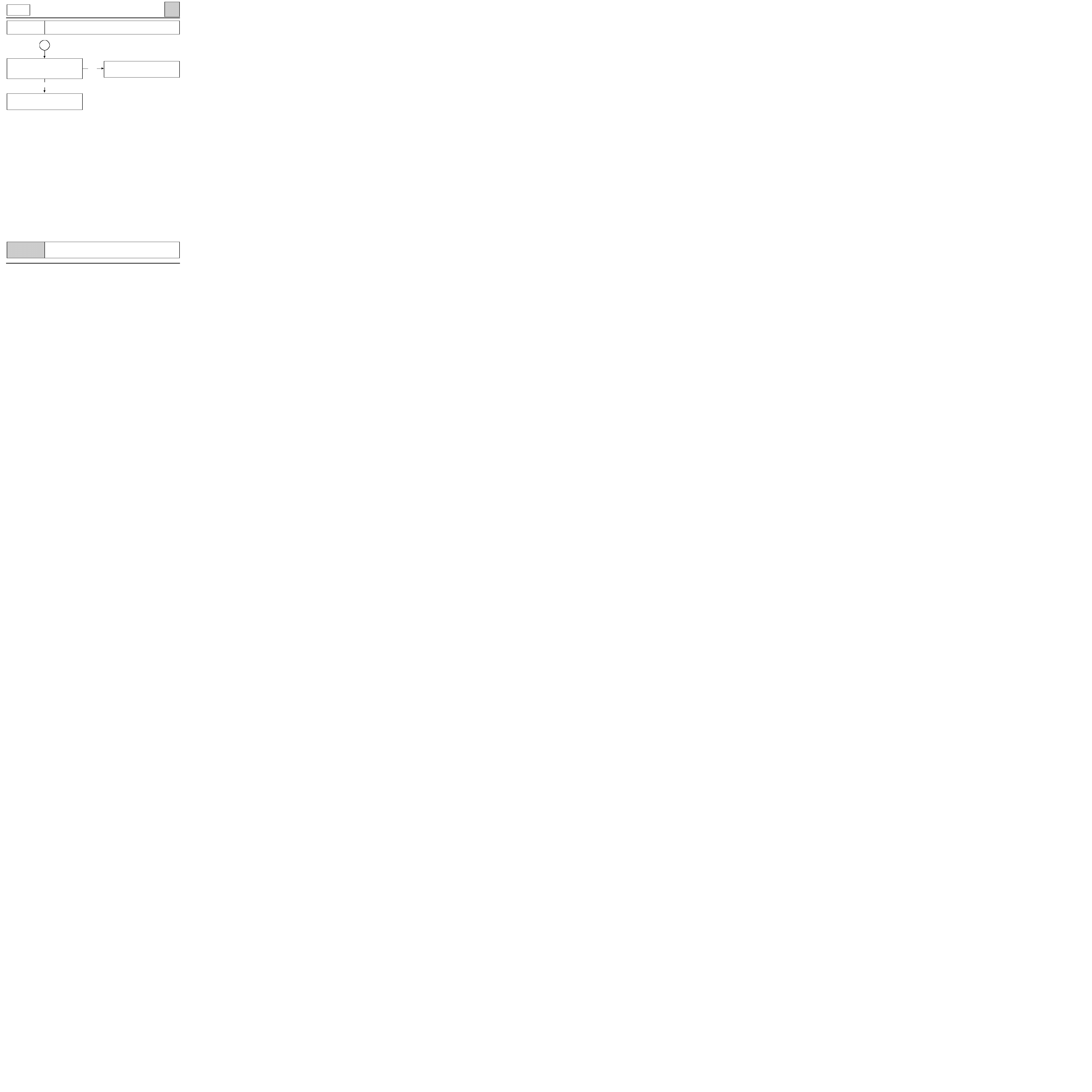
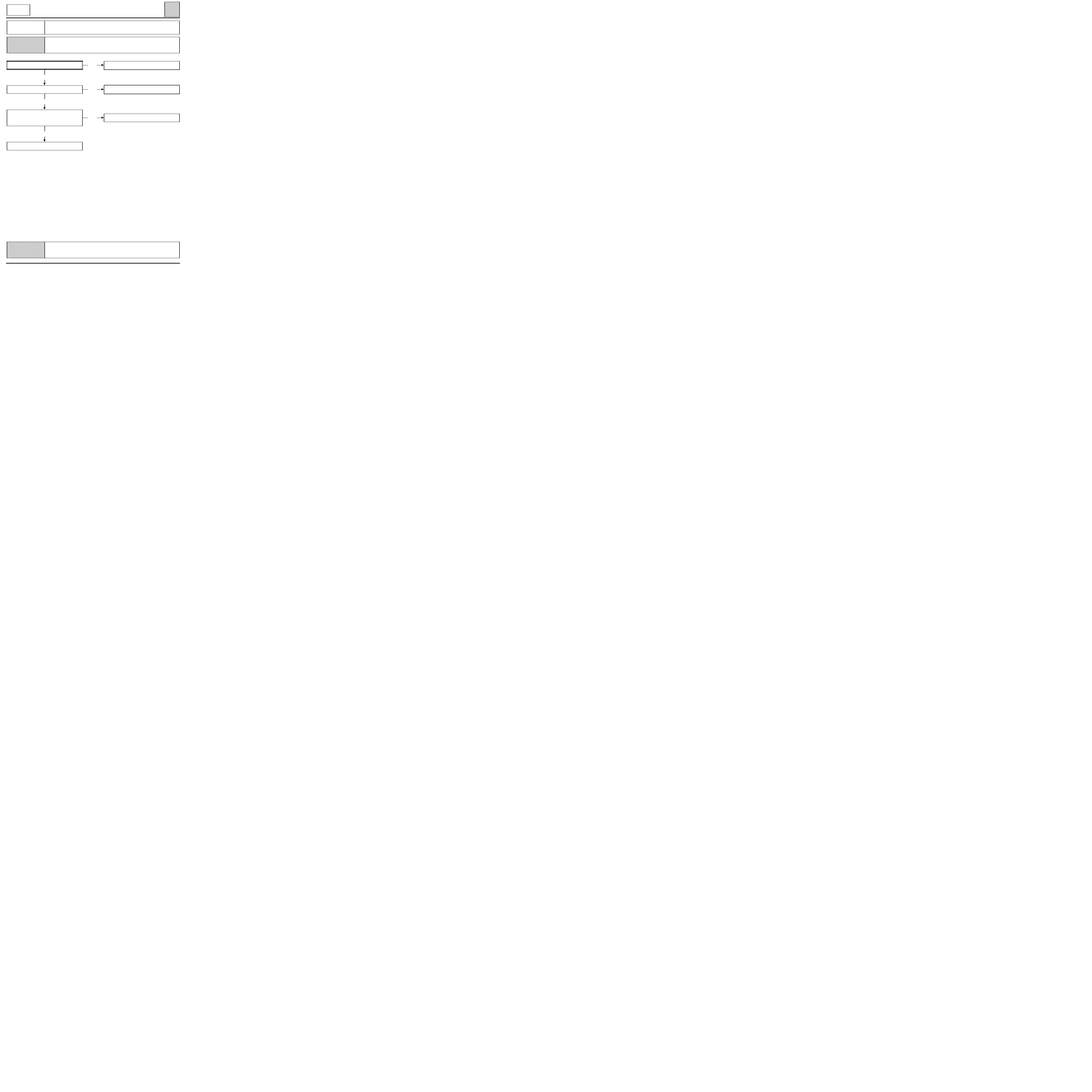
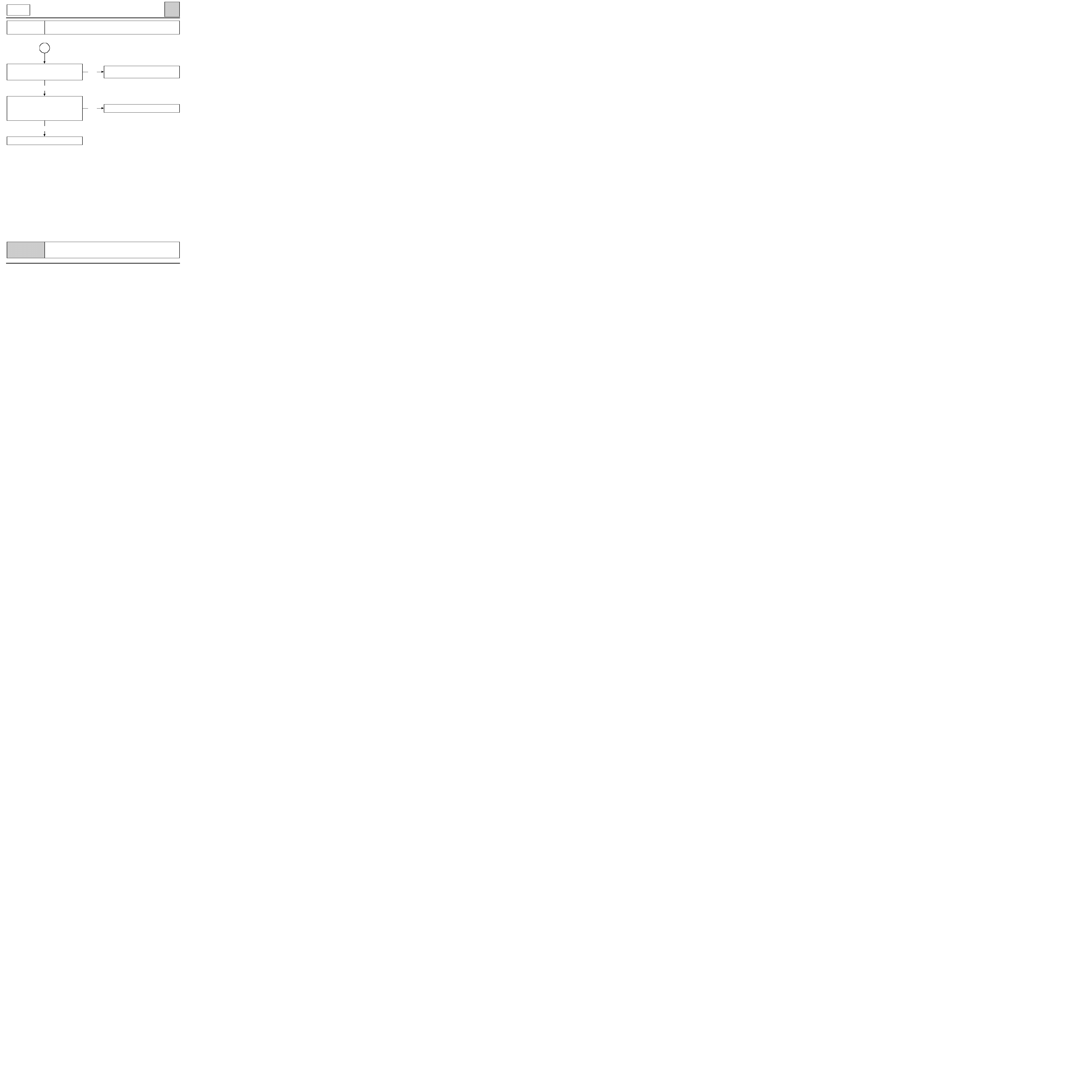
CHART 1
AIR DISTRIBUTION PROBLEMS
Before carrying out any work, check that the customer uses the air conditioning
correctly.
Non regulated air conditioning.
NOTES
yes
yes
A
yes
no
Place the passenger compartment
fan on full,
temperature control on
maximum heat or maximum cold,
and move the air distribution control.
Check that the air output
corresponds to the selection.
Is it correct?
The air distribution is correct.
If necessary, explain how the system works to
the customer again.
Check visually or by touch, on the right-hand
side of the air distribution unit,
that moving the control
moves the sprockets
and the lever.
Do they move?
Check the connection of the cable
to the air distribution unit
and the control panel
and check the condition of the cable and its
retainer. Is it correct?
Change the control cable
or repair the connection of the cable (clip)
or change the faulty part
(control panel or distribution unit).
If the fault persists,
remove the air distribution unit and
check the distribution flaps.
Repair or change the assembly.
In the case of a ventilation problem,
check the ventilation ducts
and the vents.
Repair if necessary.
Check the adjustment of the air distribution
flap control cable.
62-19
c11010.0
AIR CONDITIONING
Fault finding charts
62
KANGOO
ALL TYPES
Check that the system operates correctly.
AFTER
REPAIR
yes
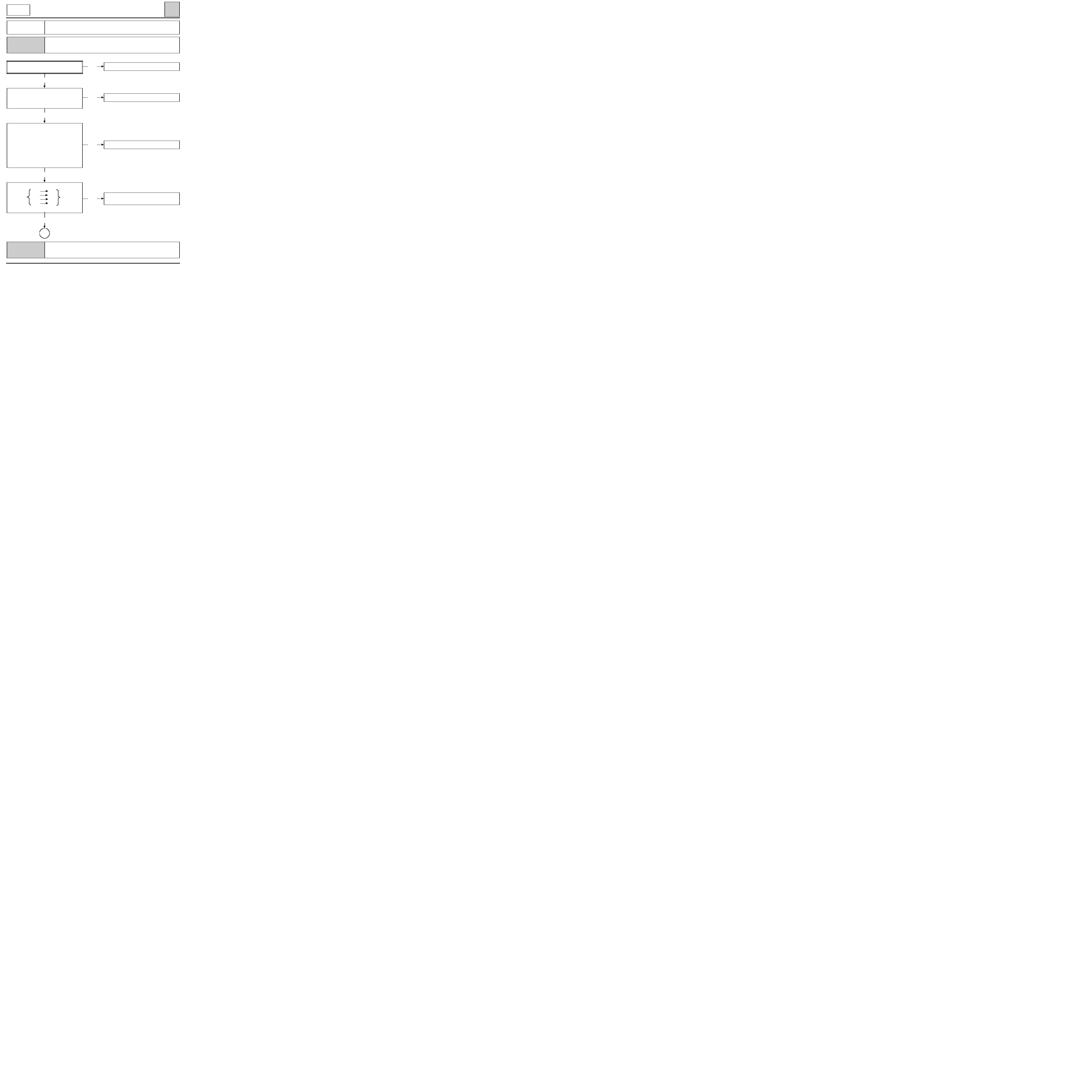
CHART 1
CONT
A
no
Check the condition of the kinematic
(sprockets, levers...) on the air distribution
unit and the control panel.
Is it correct?
Remove the air distribution unit and check
the distribution flaps.
Repair or change the unit.
Repair if possible,
otherwise change the distribution unit or the
control panel.
62-20

c11010.0
AIR CONDITIONING
Fault finding charts
62
KANGOO
ALL TYPES
Check that the system operates correctly.
AFTER
REPAIR
yes
CHART 2
AIR FLOW PROBLEM
Before carrying out any work, check that the customer uses the air conditioning
correctly.
Non regulated air conditioning.
NOTES
no
yes
yes
yes
See CHART 1.
no
no
End of fault finding.
Does the passenger compartment fan
operate?
no
See CHART 9.
Repair or clean or change
the particle filter.
Check the air intake circuit, scuttle panel
grille, particle filter, rain shield.
Are they correct?
Check that the air extraction circuit
is not blocked.
Repair if necessary.
Does the fault persist?
Is it a passenger compartment
air distribution problem?
Remove the heater radiator.
It must be blocked, clean or change it
(only valid for vehicles which have been
driven without the particle filter).
62-21
c11010.0
AIR CONDITIONING
Fault finding charts
62
KANGOO
ALL TYPES
Check that the system operates correctly.
AFTER
REPAIR
no
CHART 3
HEATER PERFORMANCE POOR
NOTES
yes
Advise the customer how to use the heating
system correctly
(eg. : Do not place the passenger
compartment fan on full when starting from
cold, turn it up gradually instead).
Carry out a road test to observe the customer
complaints.
Is the test satisfactory?
yes
A
yes
yes
no
See CHART 1.
no
no
End of fault finding.
Before carrying out any work, check that the customer uses the air conditioning
correctly.
Non regulated air conditioning.
Visually check that
the action of the control moves
the mixing flap.
Does the flap move?
Visually check
whether the flap travel is complete.
Is it complete?
Check the cooling circuit
(correct filling and bleeding),
the condition of the circuit (pipes,
connections, conformity
of the circuit...).
Repair if necessary.
Does the fault persist?
Readjust the control cable
(cable which controls the sprockets to the
right of the air distribution unit).
62-22
c11010.0
AIR CONDITIONING
Fault finding charts
62
KANGOO
ALL TYPES
Check that the components which were removed are connected correctly.
Check that the system operates correctly.
AFTER
REPAIR
yes
CHART 3
CONT
A
no
Change the thermostat
.
yes
yes
no
End of fault finding.
no
End of fault finding.
With the engine cold, remove the engine
coolant thermostat and check that it is not
jammed in the open position.
Is it correct?
Check that there is no unwanted intake of
cold air into the passenger compartment
(seals, grommets, cables ...).
Repair if necessary
Does the fault persist?
Check the air inlets (particle filter)
and outlets.
Partially blocked air inlets or outlets
reduce the flow of heated air
into the
passenger compartment.
Repair if necessary.
Does the fault persist?
The heater radiator must be blocked. Remove
the radiator and clean or change it
(only valid for vehicles which have been
driven without the particle filter).
62-23

c11010.0
AIR CONDITIONING
Fault finding charts
62
KANGOO
ALL TYPES
AFTER
REPAIR
no
CHART 4
NO HEAT
NOTES
Is it an air flow problem?
yes
See CHART 2.
yes
yes
no
See CHART 1.
no
End of fault finding.
no
End of fault finding.
Before carrying out any work, check that the customer uses the air conditioning
correctly.
Non regulated air conditioning.
Check the level of coolant in the cooling
circuit.
NOTE
: if the coolant level is too low, the cir-
cuit may become unprimed when driving at
low load and at idle.
Repair if necessary.
Does the fault persist?
Visually check that moving the control
moves the mixing flap.
Does it move?
yes
Check the coolant circuit.
NOTE
: fitting an oil, water or air cooler which
has not been approved by the research centre
and which is incorrectly connected may re-
duce or even stop the flow of coolant in the
heater radiator.
Repair the coolant circuit if necessary.
Does the fault persist?
Remove the heater radiator.
Clean or change it if necessary.
Check that the components which were removed are connected correctly.
Check that the system operates correctly.
62-24

c11010.0
AIR CONDITIONING
Fault finding charts
62
KANGOO
ALL TYPES
Check that the system operates correctly.
AFTER
REPAIR
yes
CHART 5
TOO HOT
NOTES
no
See CHART 1.
no
Readjust the cable
(to the right of the air distribution unit).
yes
yes
See CHART 11.
no
Before carrying out any work, check that the customer uses the air conditioning
correctly.
Non regulated air conditioning.
Visually check that moving the control
moves the mixing flap.
Does it move?
Check that the flap travel
is complete.
Is the travel complete?
Check the operation
of the recirculation flap.
Is it jammed in the recirculation position?
Check the operation
of the engine coolant thermostat.
Change the thermostat if necessary.
62-25
c11010.0
AIR CONDITIONING
Fault finding charts
62
KANGOO
ALL TYPES
AFTER
REPAIR
yes
CHART 6
HEATING INADEQUATE IN THE REAR
NOTES
no
Free the air outlets.
None.
Check that the air inlets at the rear of the
centre console are not blocked.
(floor carpet...).
Are they correct?
Remove the centre console and check
that the connection and sealing between the
air distribution unit and the heating duct to
the rear seats is correct.
Repair if necessary.
Check that the components which were removed are connected correctly.
Check that the system operates correctly.
62-26

c11010.0
AIR CONDITIONING
Fault finding charts
62
KANGOO
ALL TYPES
AFTER
REPAIR
CHART 7
DEICING/DEMISTING PERFORMANCE POOR
NOTES
See CHART 1.
yes
yes
yes
S
ee CHART 2.
no
yes
See CHART 3.
no
yes
no
Check that the recirculation flap is not
jammed in the recirculated air position
(see CHART 11).
Repair if necessary.
Is it a heater performance problem?
Is it an air flow problem?
Is it an air distribution problem?
Check that the windows are clean on the inside.
End of fault finding.
no
End of fault finding.
no
Check that the air extractors
are not blocked.
Repair if necessary.
Does the fault persist?
Ensure that there are no water leaks into the
passenger compartment which would
significantly increase the humidity level and
reduce the effectiveness of the demisting.
Locate the leak and repair it.
Does the fault persist?
Check that the components which were removed are connected correctly.
Check that the system operates correctly.
62-27
c11010.0
AIR CONDITIONING
Fault finding charts
62
KANGOO
ALL TYPES
AFTER
REPAIR
no
CHART 8
VENTILATION PERFORMANCE POOR
NOTES
Is it an air flow problem?
yes
See CHART 2.
yes
See CHART 1.
no
yes
End of fault finding.
Is it an air distribution problem?
Check that the mixing flap
travel is complete.
Is is correct?
None.
no
Readjust the cable.
Check that the components which were removed are connected correctly.
Check that the system operates correctly.
62-28
Check the condition of the wiring between:
B2
A2
control
B3
A1
resistance
panel
B4
C4
unit
B5
C1
Is the wiring in good condition?
yes
c11010.0
AIR CONDITIONING
Fault finding charts
62
KANGOO
ALL TYPES
AFTER
REPAIR
yes
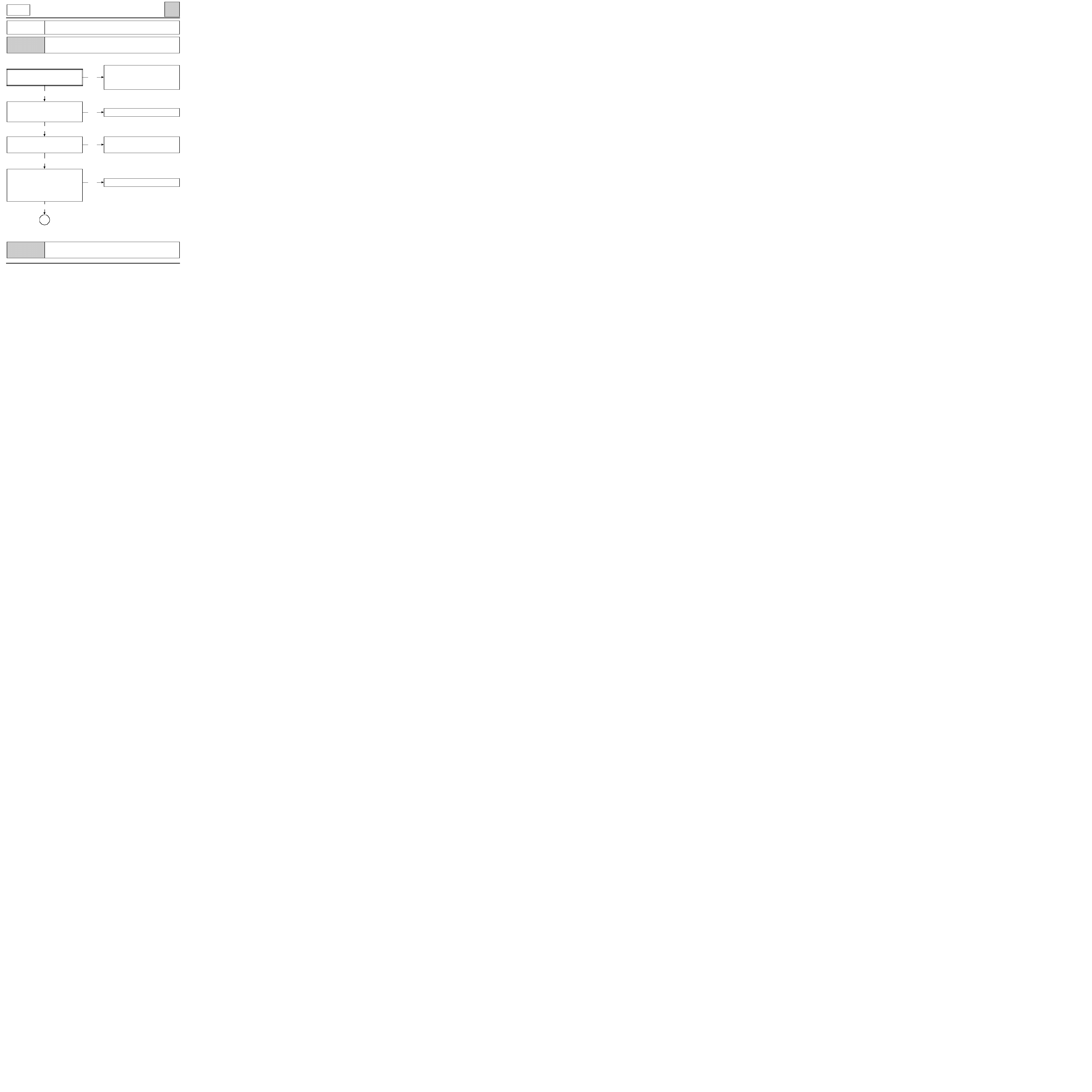
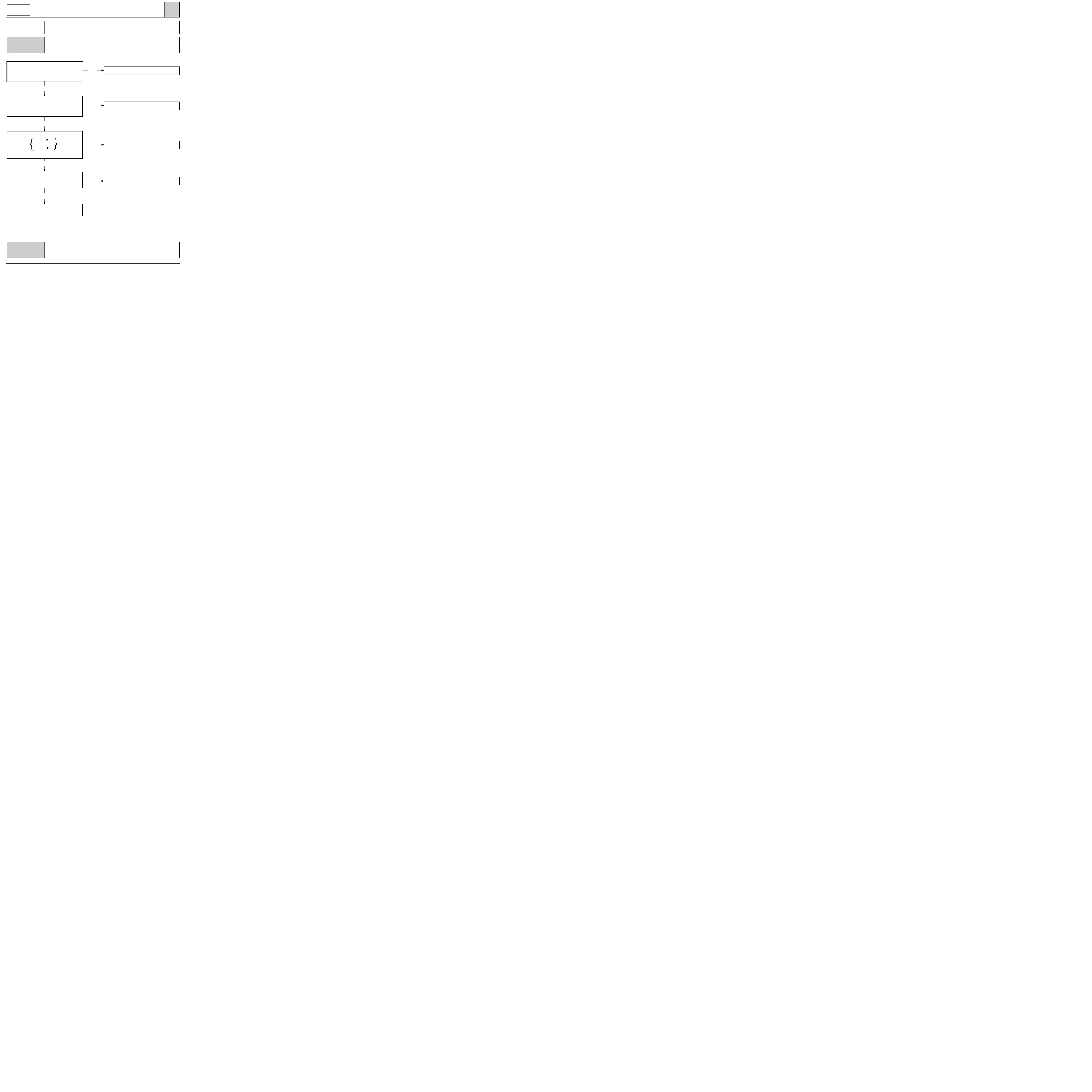
CHART 9
PASSENGER COMPARTMENT FAN DOES NOT OPERATE
NOTES
Check fuses +battery, +fuse board, +side
lights. Are the fuses in good condition?
no
Change the faulty fuse(s).
no
End of fault finding.
yes
no
Change the control panel.
yes
no
Repair the faulty
electrical wiring.
A
Before carrying out any work, check that the customer uses the air conditioning
correctly.
Non regulated air conditioning.
Check the connections between the fuses
and the instrument panel connector.
Repair if necessary.
Does the fault persist?
With the ignition on and the air conditioning
selected, position the ventilation at the
various speeds and check that 12 V
is present on the tracks of the
control panel connector:
- B5 in position 1,
- B4 in position 2,
- B2 in position 3,
- B3 in position 4.
Is 12 V present?
Check that the components which were removed are connected correctly.
Check that the system operates correctly.
62-29
c11010.0
AIR CONDITIONING
Fault finding charts
62
KANGOO
ALL TYPES
AFTER
REPAIR
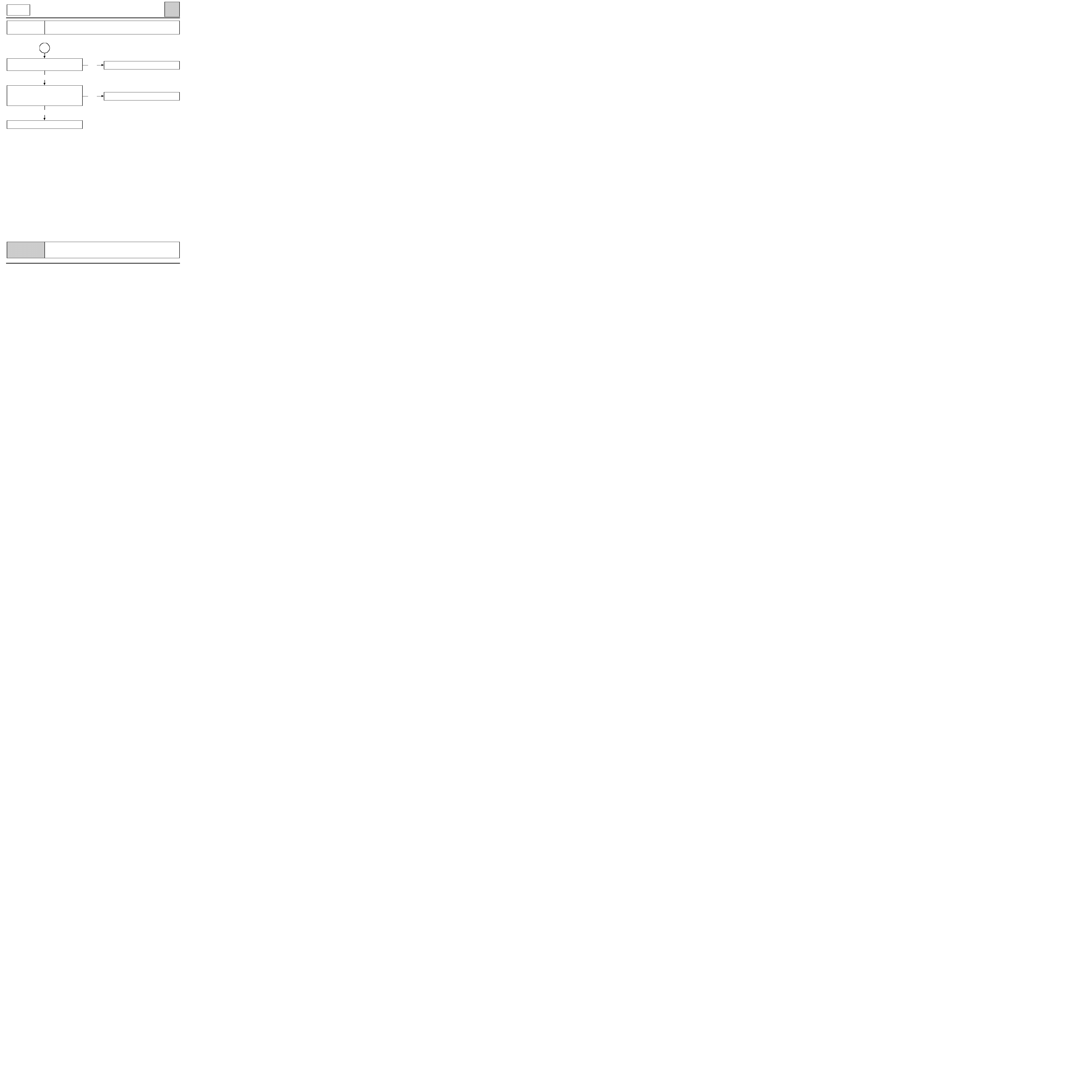
CHART 9
CONT
A
no
yes
Repair the electrical wiring.
yes
Change the resistor unit.
no
Change the fan.
Supply the fan with 0 and 12 V.
Does the fan operate?
Check the condition of the electrical wiring
between the the fan and tracks A1 and A2 of
the resistor unit connector at the fan end.
Is the wiring in good condition?
Check that the components which were removed are connected correctly.
Check that the system operates correctly.
62-30

c11010.0
AIR CONDITIONING
Fault finding charts
62
KANGOO
ALL TYPES
AFTER
REPAIR
yes
CHART 10
CONTROLS STIFF
(passenger compartment inconvenience)
NOTES
no
yes
Change the flap control cable.
None.
no
End of fault finding.
Unclip the cable from the side
of the unit and check the stiffness of
movement of each component, control
button and flap control
on the air distribution unit.
Is it correct?
Check the travel of the control cable.
Remove any constraints
on it:
- bending,
- cable clamped with plastic clips.
Change it if necessary.
Does the fault persist?
Change the control panel or repair the
kinematic of the flap or change the air
distribution unit.
Check that the components which were removed are connected correctly.
Check that the system operates correctly.
62-31
Check the insulation and continuity of the
electrical wiring between:
computer
26
B3
resistance
blue 30-way
unit
connector
27
B2
connector
Is the wiring in good condition?
yes
Check the condition of the electrical wiring
between:
control
computer
panel
A2
3
15-way
connector
Is the wiring in good condition?
yes
c11010.0
AIR CONDITIONING
Fault finding charts
62
KANGOO
ALL TYPES
AFTER
REPAIR
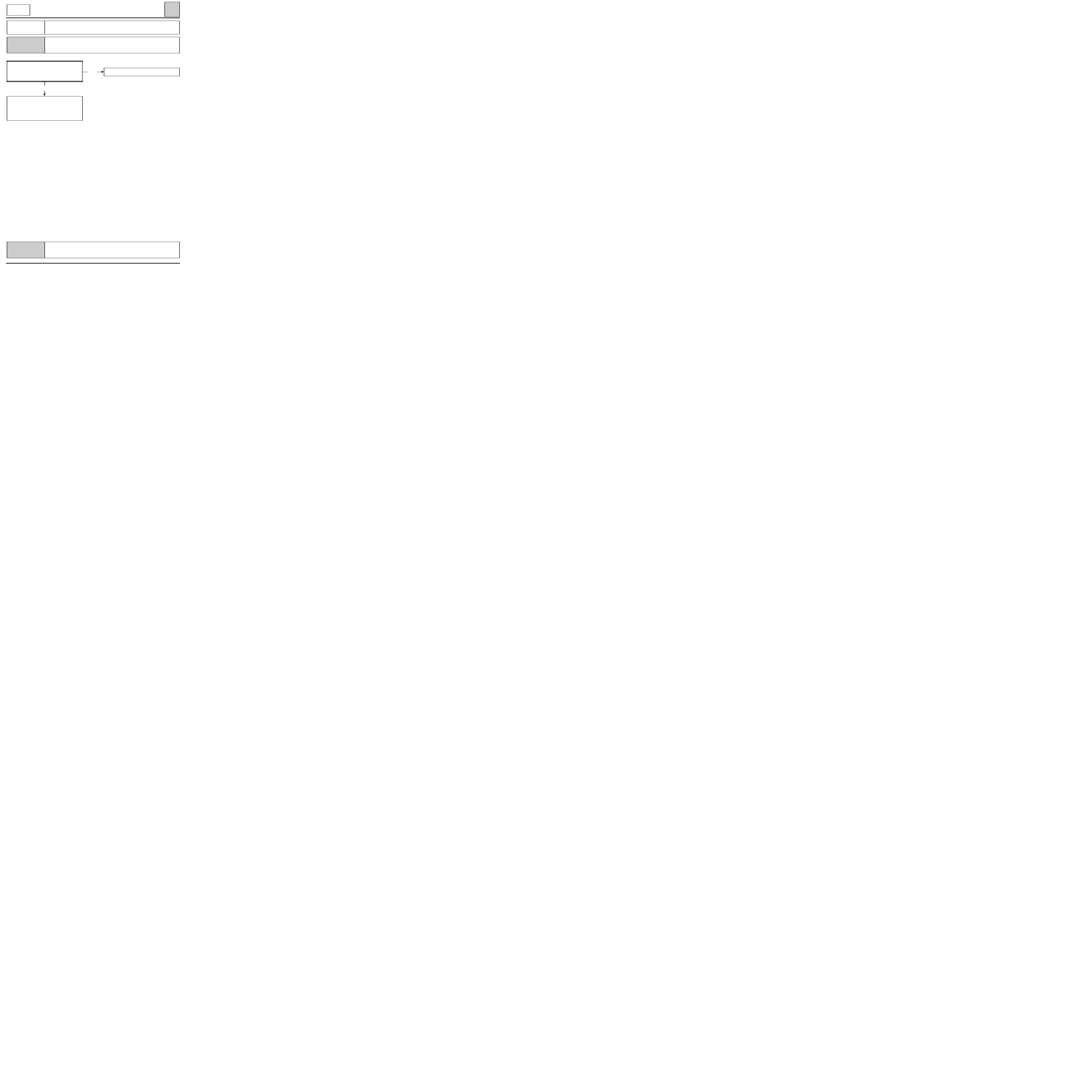
CHART 11
RECIRCULATION FLAP DOES NOT OPERATE
NOTES
no
Repair the faulty wiring.
no
Change the control panel.
no
Repair the faulty
electrical wiring.
yes
A
Before carrying out any work, check that the customer uses the air conditioning
correctly.
Non regulated air conditioning.
First of all check the condition of fuses
+battery, + fuse board, +after ignition.
Change them if necessary.
With the ignition on and air recirculation
selected, check that 12 V is present on track
A2 of the control panel.
Is 12 V present?
Check that the components which were removed are connected correctly.
Check that the system operates correctly.
62-32
c11010.0
AIR CONDITIONING
Fault finding charts
62
KANGOO
ALL TYPES
AFTER
REPAIR
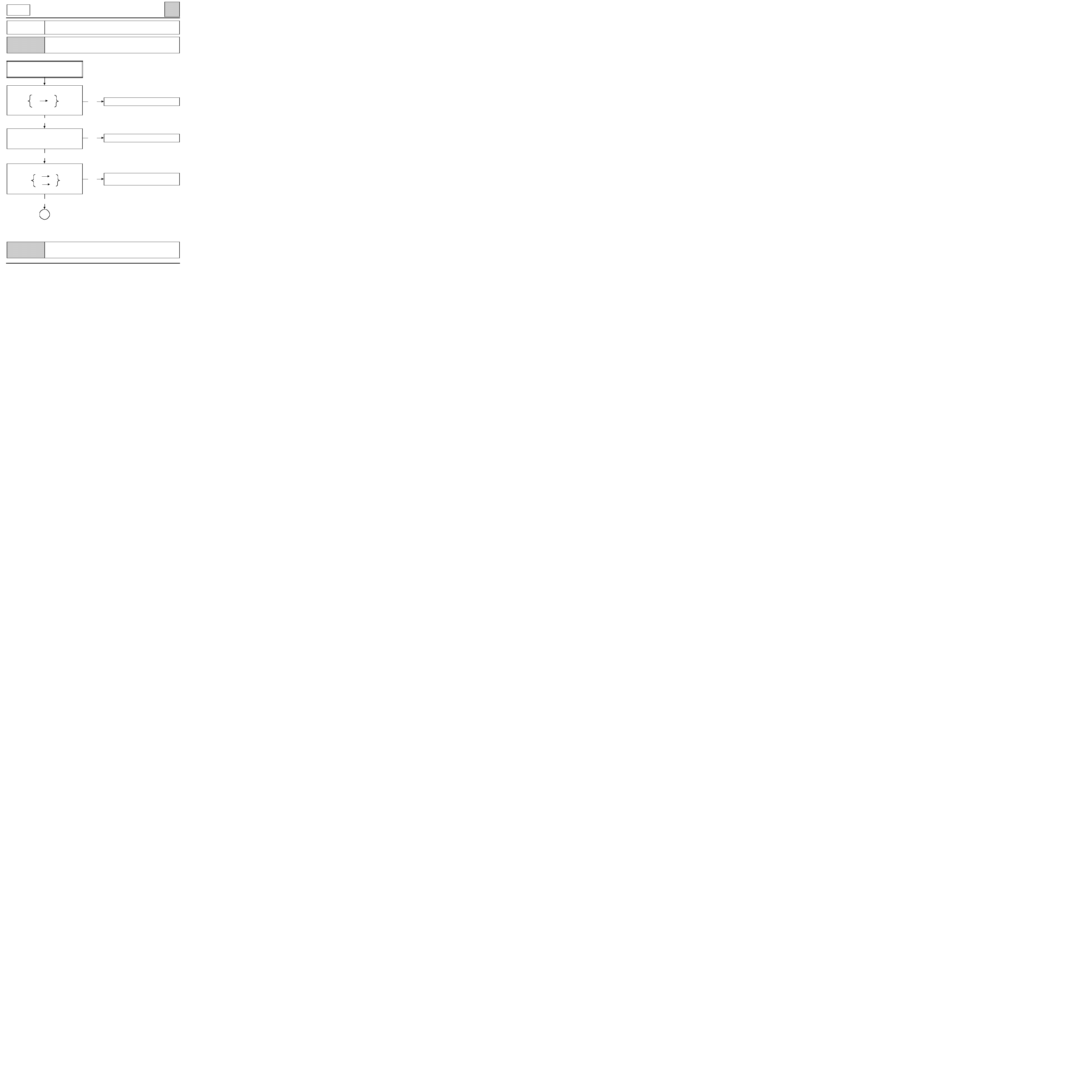
CHART 11
CONT
yes
Change the recirculation motor.
A
no
Repair the faulty
electrical wiring.
no
End of fault finding.
yes
Check the electrical wiring between the
recirculation motor and the resistor unit.
Is it in good condition?
Check that the recirculation flap control
sprockets are in good condition and that the
flap is not jammed.
Repair if necessary.
Does the fault persist?
Check that the components which were removed are connected correctly.
Check that the system operates correctly.
62-33
yes
Check the electrical wiring between:
air
2
1
conditioning
compressor
computer
17
1
Is the wiring on good condition?
yes
c11010.0
AIR CONDITIONING
Fault finding charts
62
KANGOO
ALL TYPES
AFTER
REPAIR
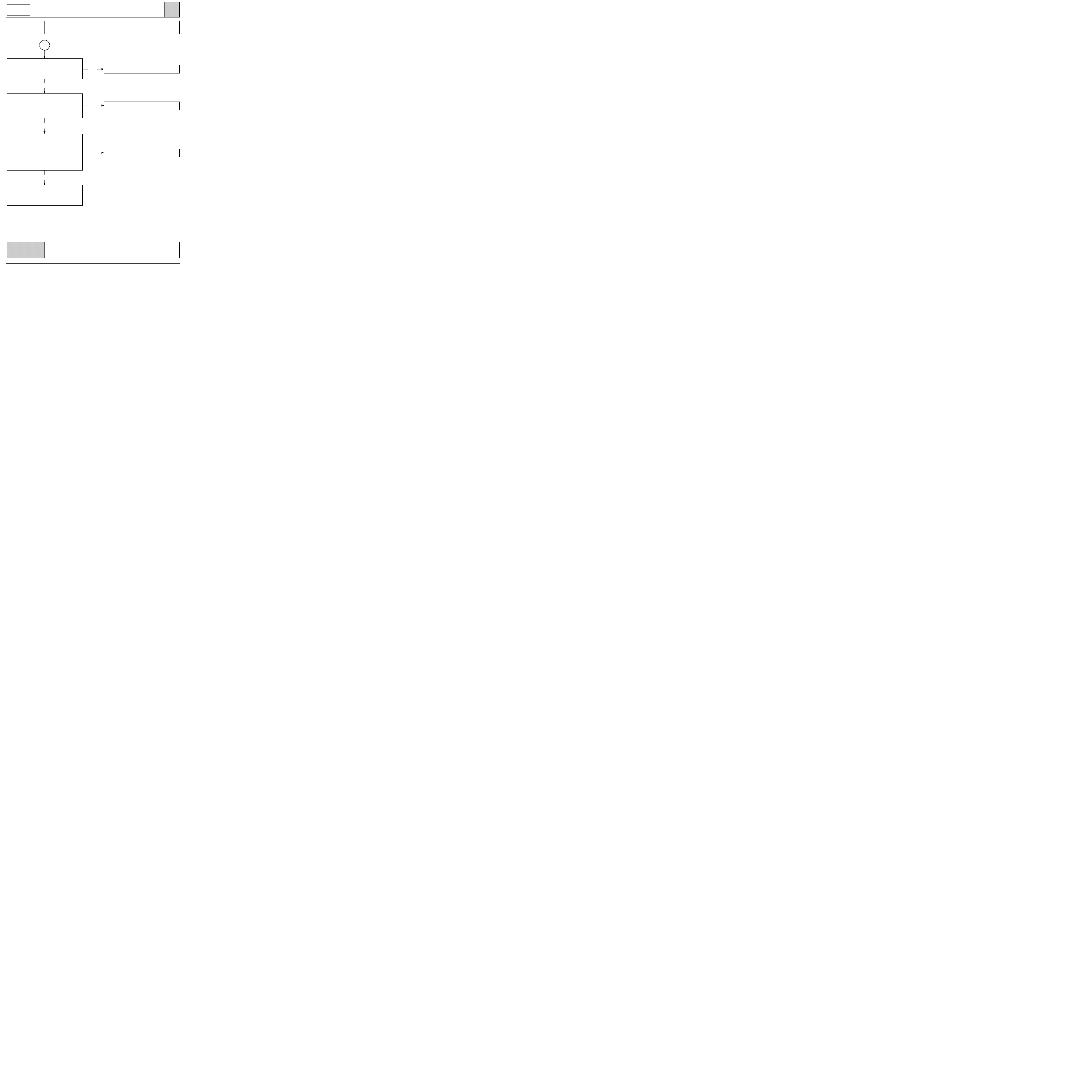
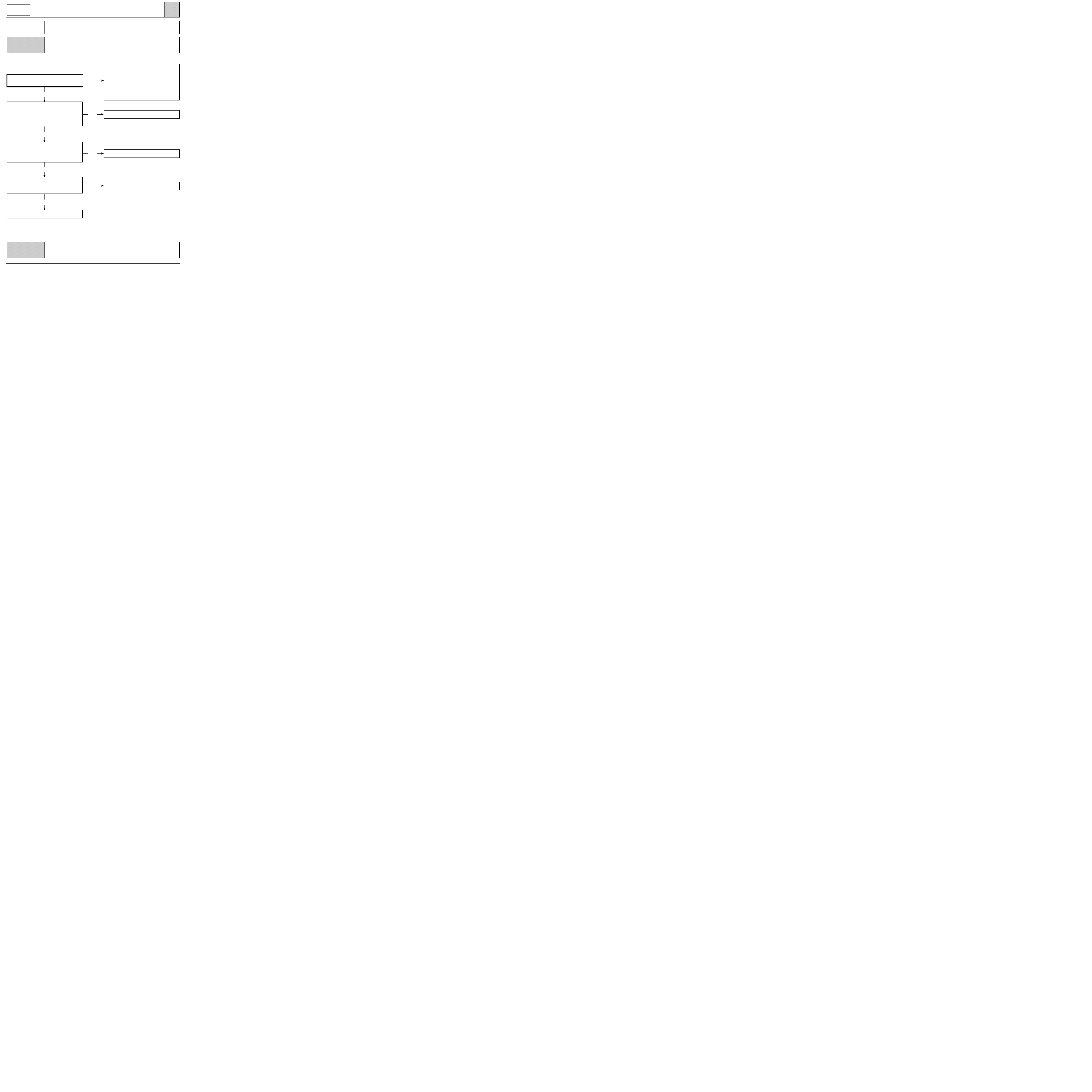
CHART 12
AIR CONDITIONING PROBLEMS
No cold air
NOTES
no
Change the control panel.
no
Repair the wiring.
yes
no
Repair the wiring.
yes
no
Change the compressor.
Non regulated air conditioning.
The passenger compartment fan operates.
With the heating and ventilation selected,
check that there is a voltage
on track A1 of the control panel.
Is there a voltage?
Check the connections between track A1 of
the control panel and track 2
of the air conditioning computer.
Is the wiring in good condition?
Using the XR25, enter G21*
(compressor clutch control).
Does the compressor cut in?
Change the
air conditioning computer.
Check that the components which were removed are connected correctly.
Check that the system operates correctly.
62-34

yes
Check the connections between:
air
9
A
fluid
conditioning
pressure
computer
10
B
sensor
Is the wiring in good condition?
c11010.0
AIR CONDITIONING
Fault finding charts
62
KANGOO
ALL TYPES
AFTER
REPAIR
no
CHART 12A
AIR CONDITIONING PROBLEMS
No cold air
NOTES
yes
Refer to left-hand bargraph 13.
no
Top up the coolant circuit.
yes
no
Repair the faulty
electrical wiring.
Change the pressure sensor.
Non regulated air conditioning.
The passenger compartment fan operates.
Check that left-hand bargraph 13 is
extinguished. This relates to the inhibiting of
heating/ventilation/air conditioning by the
injection or the automatic gearbox.
Is this bargraph extinguished?
Using the XR25, measure the pressures of the
coolant circuit by entering #16 or use
pressure gauges.
The pressures should be:
- high pressure
< 28 bars,
- low pressure
> 2 bars.
Is this correct?
Check that the components which were removed are connected correctly.
Check that the system operates correctly.
62-35
c11010.0
AIR CONDITIONING
Fault finding charts
62
KANGOO
ALL TYPES
AFTER
REPAIR
CHART 13
AIR CONDITIONING PROBLEMS
Too cold
NOTES
yes
no
no
See CHART 11.
yes
no
See CHART 1.
yes
no
Readjust the cable.
yes
Change the fan assembly.
Before carrying out any work, check that the customer uses the air conditioning
correctly.
Non regulated air conditioning.
Is the fan assembly always operating?
(normal if high pressure
≥
20 bars)
Check that the recirculation flap does not
remain in the recirculated air position.
Operate the control button
and check that the flap moves.
Does it move?
Check that the action of the
heater control
moves the flap.
Does it move?
Visually check that
the flap travel is complete.
Is it correct?
Check the coolant circuit pressures using the
XR25 or pressure gauges.
The fan assembly operates if the high
pressure
≥
20 bars and stops if the pressure
≤
15 bars.
If the pressures are correct, change
the pressure sensor, otherwise, top up
the coolant circuit.
Check that the components which were removed are connected correctly.
Check that the system operates correctly.
62-36

c11010.0
AIR CONDITIONING
Fault finding charts
62
KANGOO
ALL TYPES
AFTER
REPAIR
CHART 14
AIR CONDITIONING PROBLEMS
Performance poor
NOTES
no
See CHART 14A.
no
End of fault finding.
no
See CHART 11.
no
End of fault finding.
Is it an air flow problem?
yes
See CHART 2 or CHART 9.
no
A
yes
yes
yes
Before carrying out any work, check that the customer uses the air conditioning
correctly.
Non regulated air conditioning.
Check that the compressor operates, with the
air conditioning on, passenger compartment
ventilation on maximum in recirculation
mode, engine running at idle.
Does the compressor operate?
Check the tension of the compressor belt, the
clutch air gap and its condition.
Retension the belt or change
the compressor clutch.
Does the fault persist?
yes
Ensure that the recirculation flap is in the
recirculation position in air conditioning
recirculation mode.
Is it in this position?
Check that the flap travel is complete,
readjust the cable if necessary.
Does the fault persist?
Check that the components which were removed are connected correctly.
Check that the system operates correctly.
62-37
yes
c11010.0
CONDITIONING
Fault finding charts
62
KANGOO
ALL TYPES
AFTER
REPAIR
CHART 14
CONT
no
Top up the coolant circuit.
yes
no
See CHART 15.
Change the pressure sensor.
Check the cleanness of the
condenser wiring harness.
Clean or change the condenser.
If the fault persists, check the operation of
the cooling fan assembly at high speed
(ventilation and air conditioning
on maximum).
It should be:
- operating if high pressure
≥
20 bars
- stopped if high pressure
≤
15 bars
Is the operation of the fan assembly normal?
Check that the components which were removed are connected correctly.
Check that the system operates correctly.
A
With the vehicle stationary, engine running
at idle, air conditioning on maximum,
measure the pressure of the coolant circuit.
If the pressure is > 28 bars, there is :
- too much fluid,
- or the operation of the fan assembly is ab-
normal,
- or the condenser is clogged,
- or the engine heats up too much.
Is the pressure < 28 bars ?
62-38
yes
Check the electrical wiring:
air
9
1
pressure
conditioning
10
4
sensor
computer
11
3
connector
and between the connector and the sensor.
Is the wiring in good condition?
c11010.0
AIR CONDITIONING
Fault finding charts
62
KANGOO
ALL TYPES
AFTER
REPAIR
CHART 14A
AIR CONDITIONING PROBLEMS
Performance poor
NOTES
yes
See CHART 14.
no
no
If the fault persists,
change the compressor.
yes
no
Repair the faulty
electrical wiring.
yes
no
Top up the coolant circuit.
Change the pressure sensor.
Before carrying out any work, check that the customer uses the air conditioning
correctly.
Non regulated air conditioning.
With the air conditioning and ventilation on
maximum and the engine running at idle,
check that the compressor operates.
Does the compressor operate?
Connect the XR25 and enter G21*
(direct compressor control).
Does the compressor operate?
Check the pressure of the coolant circuit.
The compressor should cut in for:
- low pressure
≥
2 bars,
- high pressure
≤
28 bars.
Is this correct?
Check the wiring between
the heating and ventilation computer
and the compressor clutch.
Repair if necessary.
Check that the components which were removed are connected correctly.
Check that the system operates correctly.
62-39

Check the electrical wiring between:
air
9
1
pressure
conditioning
10
4
sensor
computer
11
5
connector
and between the connector and the sensor.
Is the electrical wiring in good condition?
c11010.0
AIR CONDITIONING
Fault finding charts
62
KANGOO
ALL TYPES
AFTER
REPAIR
yes
CHART 14B
AIR CONDITIONING PROBLEMS
Performance poor
NOTES
no
yes
no
Repair the faulty electrical wiring.
yes
no
Top up the coolant.
Change the pressure sensor.
Before carrying out any work, check that the customer uses the air conditioning
correctly.
Non regulated air conditioning.
Check the operation of the fan assembly.
Connect the XR25 and enter G22* and G23*
(direct fan assembly control).
Does the fan assembly operate
at low and high speed?
Check the pressure of the coolant circuit.
The fan assembly should be:
- operating for a pressure
≥
10 bars,
- stopped for a pressure
≥
20 bars.
Is this correct?
Check the electrical wiring
between tracks 22 and 23 of the heating and
ventilation computer and the fan assembly.
Repair if necessary.
If the fault persists,
change the fan assembly.
Check that the components which were removed are connected correctly.
Check that the system operates correctly.
62-40

Check the continuity and insulation from 12
volts of the electrical wiring
between:
air
22
F2
low speed
conditioning
relay
computer
23
M2
high speed
relay
Is the wiring in good condition?
c11010.0
AIR CONDITIONING
Fault finding charts
62
KANGOO
ALL TYPES
AFTER
REPAIR
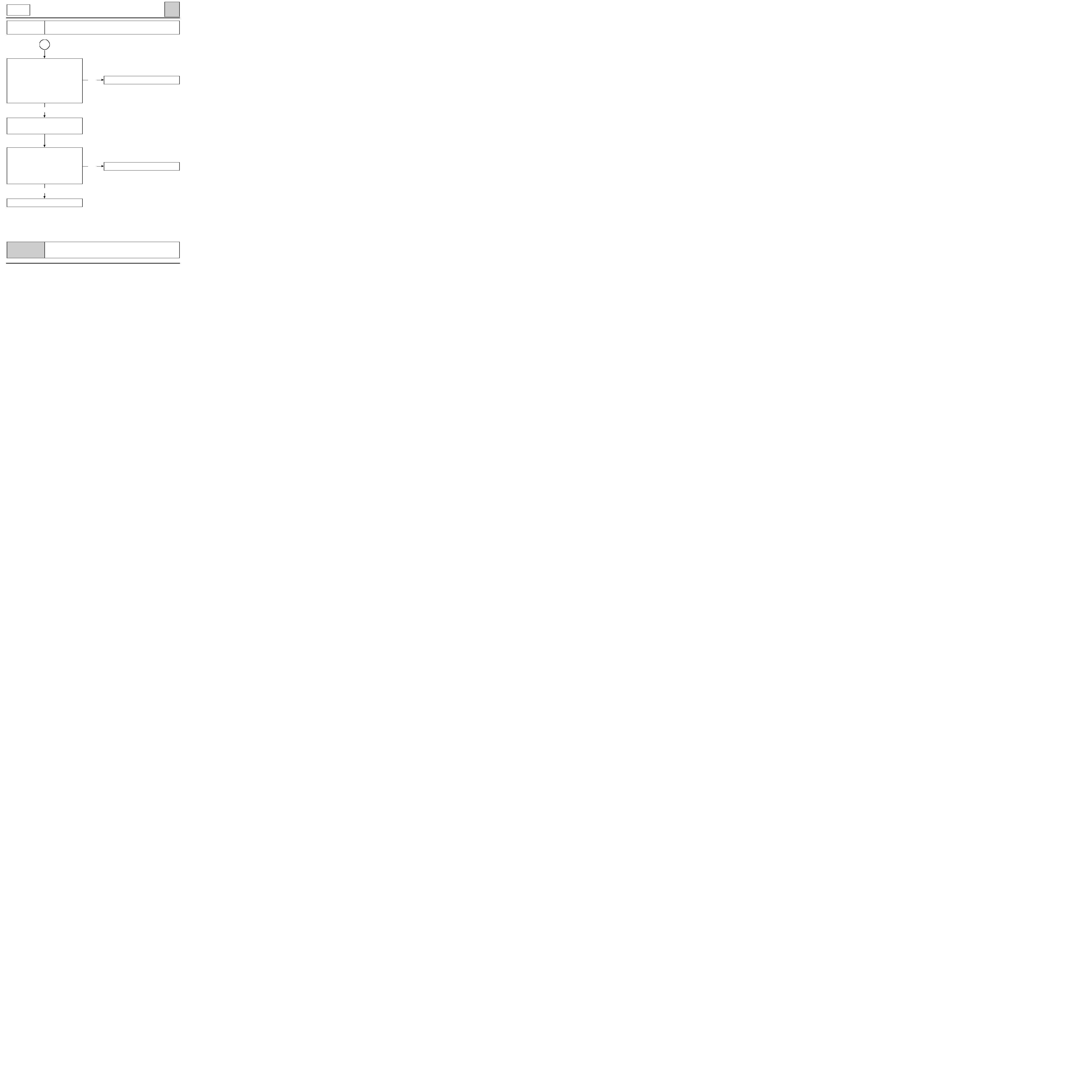
CHART 15
COOLING FAN DOES NOT OPERATE
NOTES
yes
no
Repair the faulty
electrical wiring.
no
Change the faulty relay(s).
yes
no
Repair.
yes
A
Non regulated air conditioning.
The compressor operates.
Check the condition of the fuses.
Change them if necessary.
Check that 12 volts is present on track 5 of the
low speed and high speed relays.
Is this correct?
Check that the fan assembly is correctly
supplied with 12 volts and 0 volt.
Is this correct?
Check that the components which were removed are connected correctly.
Check that the system operates correctly.
62-41
yes
Check the electrical wiring between:
heating and
9
1
inter-
ventilation
10
4
mediate
computer
11
3
connector
and between:
inter-
1
A
pressure
mediate
4
C
sensor
connector
3
B
Is the wiring in good condition?
c11010.0
AIR CONDITIONING
Fault finding charts
62
KANGOO
ALL TYPES
AFTER
REPAIR
CHART 15
CONT
A
no
Top up the coolant circuit.
yes
no
Repair the faulty
electrical wiring.
With the air conditioning selected and
ventilation on maximum, check the pressure
of the coolant circuit using the XR25 by
entering #16.
- The fan cuts in at low speed for a pressure
≥
10 bars,
- The fan cuts in at high speed for a pressure
≥
20 bars.
Are the pressure values correct?
Change the pressure sensor.
If the fault persists,
change the fan.
Check that the components which were removed are connected correctly.
Check that the system operates correctly.
62-42

c11010.0
AIR CONDITIONING
Fault finding - Associated checks
62
KANGOO
ALL TYPES
COMMAND MODE G--*
To use this function, enter G on the XR25 keypad, then the number of the command selected followed by
an asterisk.
G21*
: compressor clutch control
G22*
: fan low speed control
G23*
: fan high speed control
G24*
: recirculation motor control
G13*
: end of fault finding
COMMAND MODE #
# 08
: fan assembly speed
# 15
: engine speed
# 16
: pressure of coolant in the circuit
62-43
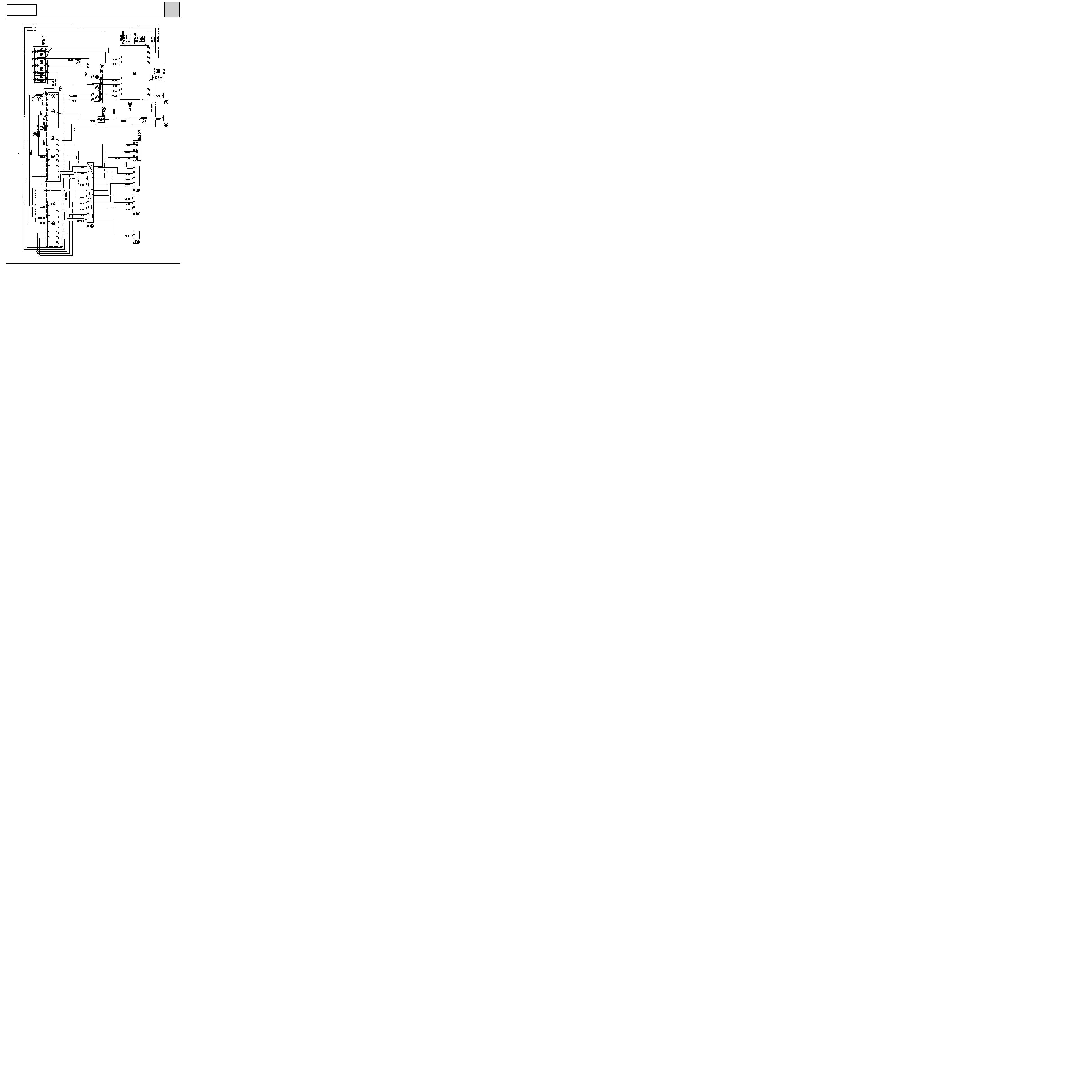
AIR CONDITIONING
Wiring diagram
62
D7F ENGINE
PRO13781
62-44

AIR CONDITIONING
Wiring diagram
62
F8Q ENGINE
PRO13948
62-45

AIR CONDITIONING
Wiring diagram
62
E7J ENGINE
PRO14441
62-46

AIR CONDITIONING
Wiring diagram
62
D7F/F8Q and E7J
ENGINES
120
Injection computer
171
Air conditioning clutch
206
Air control pressure switch
225
Diagnostic socket
234
Fan assembly relay
236
Fuel pump relay
248
Fan assembly thermal switch
260
Fuse box
319
Air conditioning control panel
320
Base fan assembly/Air conditioning
419
Air conditioning control unit
466
Shunt box
597
Engine fuse box
700
Cooling fan relay (low speed)
R67 Front of engine/Engine
NB : Evaporator sensor (depending on assembly)
62-47
TIGHTENING TORQUES (in daN.m)
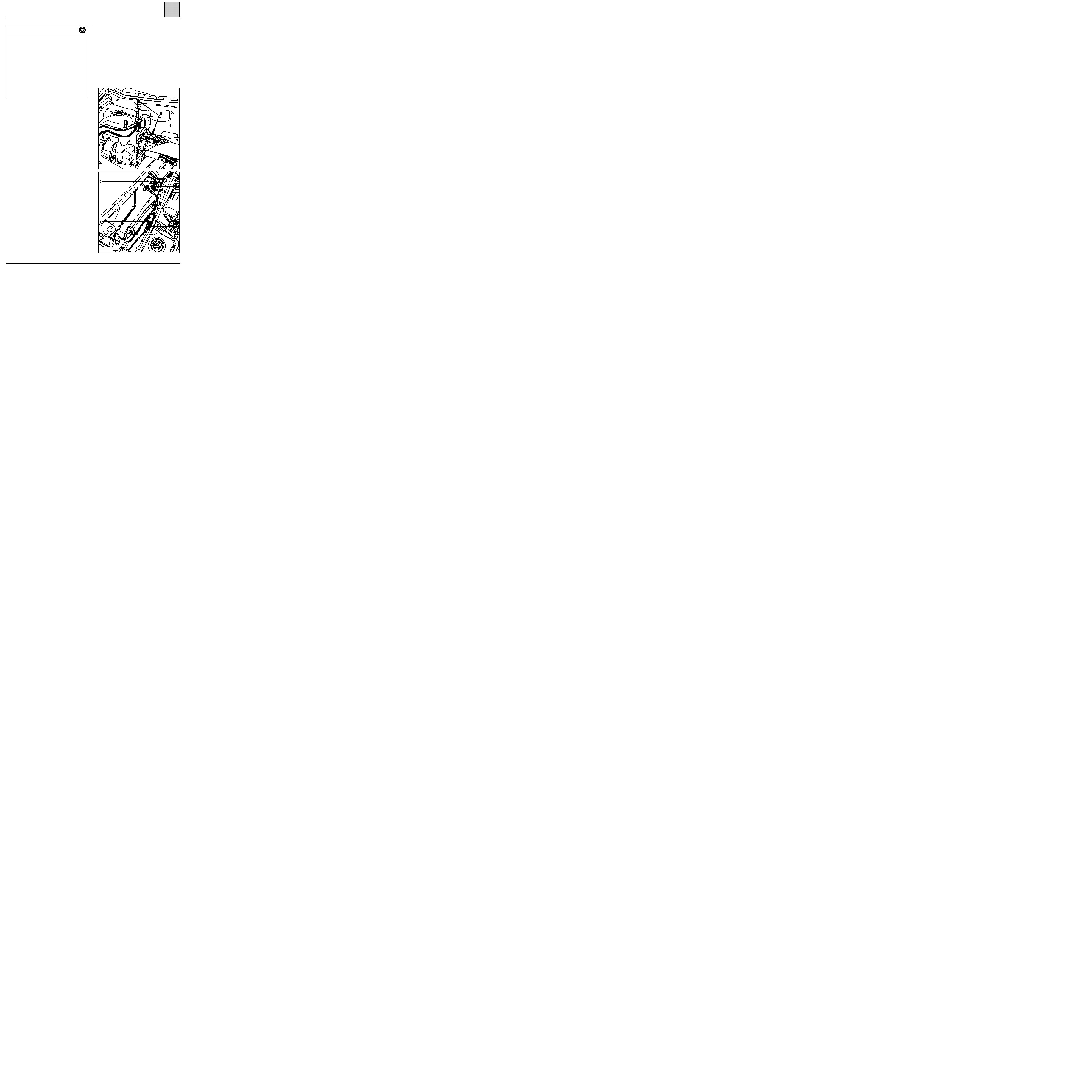
AIR CONDITIONING
Evaporator
62
13831R
Pressure relief valve to evaporator bolt
0.6
Connecting pipes to pressure relief valve
retaining nut
0.8
Pressure relief valve connecting pipe to
dehydration canister retaining bolt
0.8
Condenser connecting pipe to
dehydration canister retaining bolt
1.2
Compressor connecting pipe to condenser
retaining bolt
0.8
Connecting pipes to compressor
retaining bolt
2.1
Compressor retaining bolt
2.1
Circuit pressure sensor
0.8
REMOVAL
Disconnect the battery.
Drain the R134a coolant circuit using the filling
equipment.
Disconnect the R134a connecting pipes (bolt 1) to
the pressure relief valve.
Install the plugs on the pipes and the pressure re-
lief valve.
Remove:
- the windscreen wiper arms,
- the air inlet grille,
- the six plenum chamber closure panel (2) retai-
ning bolts (A) and remove the plenum cham-
ber,
- the evaporator protector in the plenum cham-
ber.
Disconnect the electrical connectors (4) and the
earth leads (5).
Remove the intermediate sleeve (6) between the
evaporator housing and the heater fan assembly.
13826R
62-48

AIR CONDITIONING
Evaporator
62
Move aside the dashboard by removing:
- the six steering column mounting bolts,
- the four dashboard side retaining nuts and the
two bolts behind the ashtray assembly.
NOTE:
take care to protect the sections of the
dashboard which are susceptible to damage using
cloths.
Remove the two evaporator housing mountings
behind the dashboard on the passenger side.
Remove the evaporator housing.
Carefully remove the evaporator from its housing.
REFITTING
Check that the harness tubes are not in contact
(risk of noise).
Proceed in the reverse order to removal.
Tighten the retaining nut (connecting pipes to
pressure relief valve) to 0.8 daN.m (pay attention
to the condition of the seals).
NOTE:
when refitting the dashboard, check:
- that the electrical wiring is positioned correctly,
- that the air flow pipes are positioned correctly
(glove box for example).
Create a vacuum, then fill the R134a coolant cir-
cuit using the filling equipment.
IMPORTANT
When an evaporator is changed, add 30 ml of
P.A.G. SP 10
oil to the circuit.
Use the same oil for refitting the seals taking care
to position them correctly.
62-49

AIR CONDITIONING
Air blower unit
62
REMOVAL
An air blower unit can only be changed following
removal of the evaporator (refer to the
"Evaporator"
section).
Remove the two heater fan assembly mounting
bolts.
Remove the heater fan assembly.
REFITTING
Refitting does not present any special points.
After refitting the heater fan assembly and the
evaporator, create a vacuum and then fill the
R134a coolant circuit using the filling equipment.
IMPORTANT
Ensure that all of the seals are positioned correct-
ly. Lubricate them with
P.A.G. SP 10
oil.
62-50

AIR CONDITIONING
Compressor
62
D7F ENGINE
13829R1
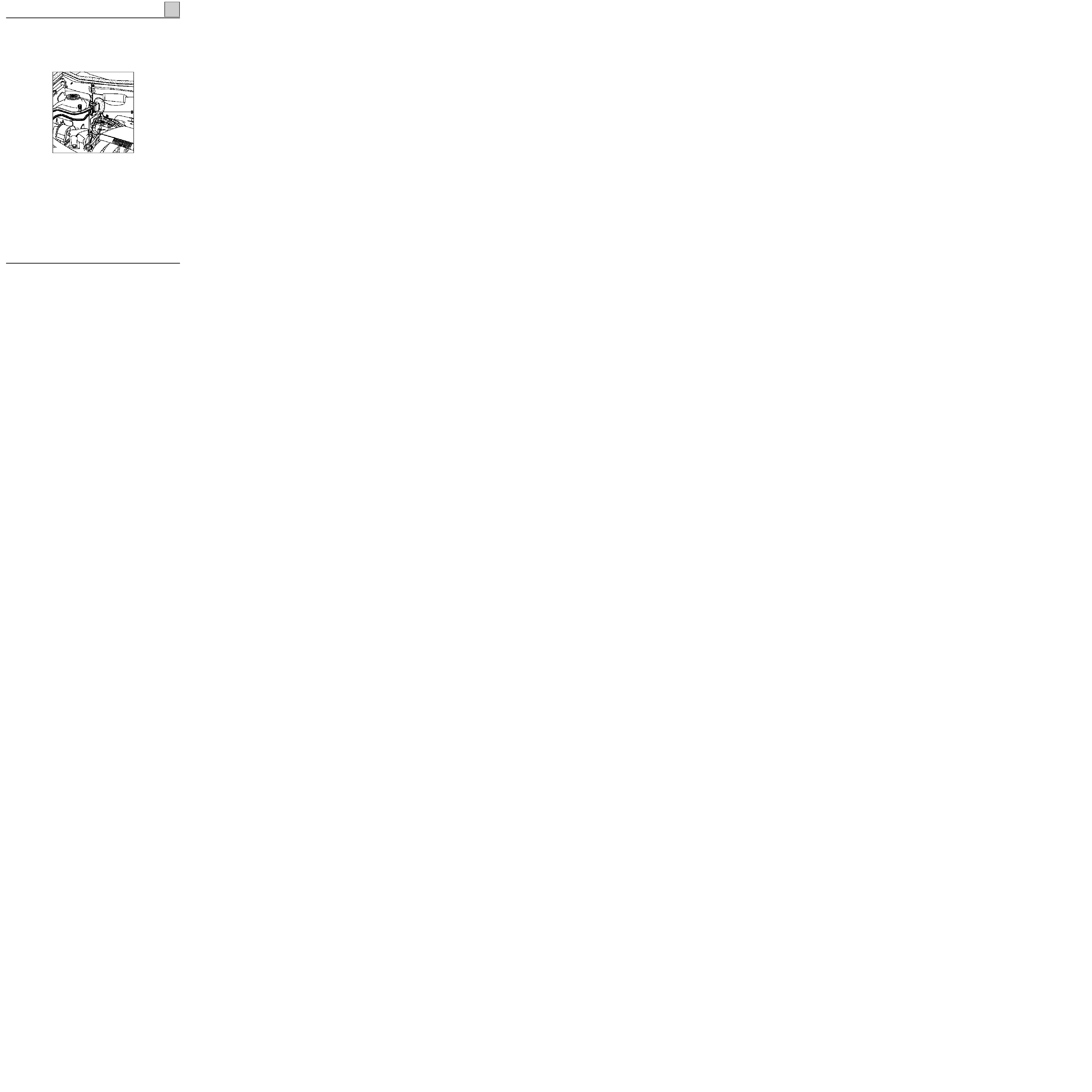
REMOVAL
Drain the R134a coolant circuit.
Disconnect the battery.
Remove:
- the compressor drive belt,
- the two connecting pipes (A),
- the retaining strut bolt (B),
- the three compressor retaining bolts (C).
Remove the compressor.
NOTE:
it is essential to place plugs on the pipes
and on the compressor to prevent the entry of hu-
midity into the circuit.
REFITTING
If it is changed, the compressor is supplied filled
with oil.
Position the compressor the correct way round
(filler plug facing upwards).
Tighten the three bolts (C) (Tightening torque:
2.1 daN.m
).
Fit the strut retaining bolts (B).
Refit the two R134a coolant pipes (A) on the
compressor (Tightening torque:
2.1
daN.m
).
Fit the drive belt and tension it.
Create a vacuum, then fill the R134a coolant cir-
cuit using the filling equipment.
NOTE:
when refitting the connecting pipes on the
compressor, it is essential to fit all the bolts, then
bring them into contact before torque tightening
them. The aim is to ensure that the pipe is positio-
ned correctly so that it is not damaged at the cut
off (1).
Check the condition of the seals and lubricate
them with
P.A.G. SP 10
oil.
IMPORTANT
When changing the compressor, it is essential to
top up the oil.
62-51
AIR CONDITIONING
Compressor
62
F8Q ENGINE
REMOVAL
Place the vehicle on a lift.
Drain the R134a coolant circuit.
Disconnect the battery.
Remove the front bumper.
From above, remove:
- the compressor drive belt,
- the two connecting pipes (A),
- the connecting pipe retaining lug (B).
From underneath the vehicle, remove the three
compressor retaining bolts and remove the
compressor.
NOTE:
it is essential to fit plugs on the pipes and
on the compressor to prevent humidity from ente-
ring the circuit.
13947R
REFITTING
If it is changed, the compressor is supplied filled
with oil.
Position the compressor the correct way round
(filler plug facing upwards).
Tighten the three bolts (C) (Tightening torque:
2.1 daN.m
).
Refit the two R134a coolant pipes (A) on the
compressor (Tightening torque:
2.1
daN.m
) as well
as bracket (B).
Fit the drive belt and tension it.
Create a vacuum, then fill the R134a coolant cir-
cuit using the filling equipment.
NOTE:
when refitting the connecting pipes on the
compressor, it is essential to fit all the bolts, then
bring them into contact before torque tightening
them. The aim is to ensure that the pipe is positio-
ned correctly so that it is not damaged at the cut
off (1).
Check the condition of the seals and lubricate
them with
P.A.G. SP 10
oil.
IMPORTANT
When changing the compressor, it is essential to
top up the oil.
62-52

AIR CONDITIONING
Compressor
62
E7J ENGINE
REMOVAL
Place the vehicle on a lift.
Drain the R134a coolant circuit.
Disconnect the battery.
Remove:
- the engine undertray,
- the bumper.
From above, remove:
- the accessories drive belt,
- the two R134a connecting pipes (A).
From underneath the vehicle, remove:
- the compressor drive belt,
- the compressor retaining bolts and remove the
the compressor.
NOTE:
it is essential to fit plugs on the pipes and
on the compressor to prevent humidity from ente-
ring the circuit.
REFITTING
If it is changed, the compressor is supplied filled
with oil.
Position the compressor the correct way round
(filler plug facing upwards).
Tighten the retaining bolts (C) (Tightening tor-
que: 2.1 daN.m).
Refit the two R134a coolant pipes (A) on the
compressor (Tightening torque:
2.1
daN.m
).
Fit the drive belts and tension them.
Create a vacuum, then fill the R134a coolant cir-
cuit using the filling equipment.
NOTE:
when refitting the connecting pipes on the
compressor, it is essential to fit all the bolts, then
bring them into contact before torque tightening
them. The aim is to ensure that the pipe is positio-
ned correctly so that it is not damaged at the cut
off (1).
Check the condition of the seals and lubricate
them with
P.A.G.
SP 10
oil.
IMPORTANT
When changing the compressor, it is essential to
top up the oil.
14229R
62-53
AIR CONDITIONING
Condenser
62
13828R
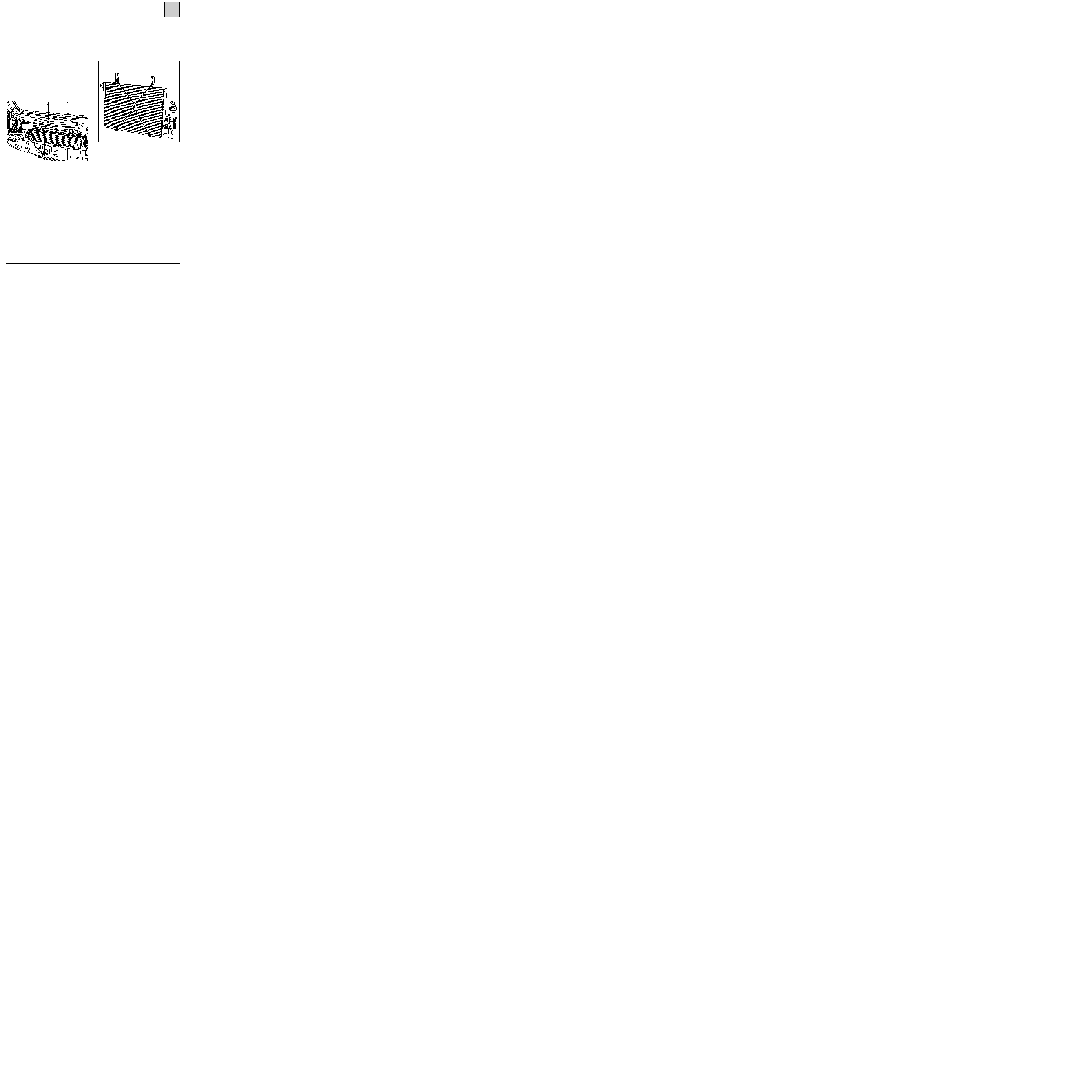
REMOVAL
It is not necessary to use a lift.
Drain the R134a coolant circuit.
Disconnect the battery.
Remove:
- the plastic air deflector on the upper crossmem-
ber,
- the seal (1),
- the upper crossmember (2),
- the retaining bolt (3),
- the two R134a coolant pipes (4) (fit plugs to
prevent the entry of humidity),
- the two radiator upper retaining bolts.
Move the radiator-condenser assembly as far back
as possible towards the engine.
Remove the four condenser to radiator retaining
bolts (6).
Carefully remove the condenser.
REFITTING
Proceed in the reverse order to removal.
Check the condition of the seals.
Create a vacuum, then fill the circuit with R134a
using the filling equipment.
IMPORTANT
When changing the condenser, add 30 ml of
P.A.G. SP 10
oil to the circuit.
NOTE:
tightening torque of bolts (6) : 0.8 daN.m.
13830R
62-54
AIR CONDITIONING
Pressure relief valve
62
13826R1
REPLACEMENT
Drain the R134a coolant circuit using the filling
equipment.
Remove:
- the connecting pipes retaining nut (A),
- the two pressure relief valve to evaporator re-
taining bolts (B).
On refitting, ensure that the pipe seals are in
good condition.
Bolt tightening torques:
- bolt (A) : 0.8 daN.m,
- bolt (B) : 0.6 daN.m.
Create a vacuum, then fill the R134a coolant cir-
cuit using the filling equipment.
62-55

AIR CONDITIONING
Dehydration canister
62
13828R1
Remove the dehydration canister from under-
neath the vehicle.
Fit plugs on each hole to prevent any entry of hu-
midity into the components.
REFITTING
Proceed in the reverse order to removal.
Check that the seals are in good condition and lu-
bricate them with
P.A.G. SP 10
oil.
Create a vacuum, then fill the R134a coolant cir-
cuit using the filling equipment.
When changing the dehydration canister, add 15
ml
of
P.A.G. SP 10
oil to the circuit.
NOTE:
tightening torque of bolt (2) : 1.2 daN.m
REMOVAL
Drain the R134a coolant circuit using the filling
equipment.
Remove:
- the two radiator upper mounting bolts,
- the two mounting bolts which secure the pipes
to the dehydration canister.
Move back the radiator-condenser assembly
slightly.
Through the bumper, remove the two dehydra-
tion canister to condenser retaining bolts (1).
62-56

AIR CONDITIONING
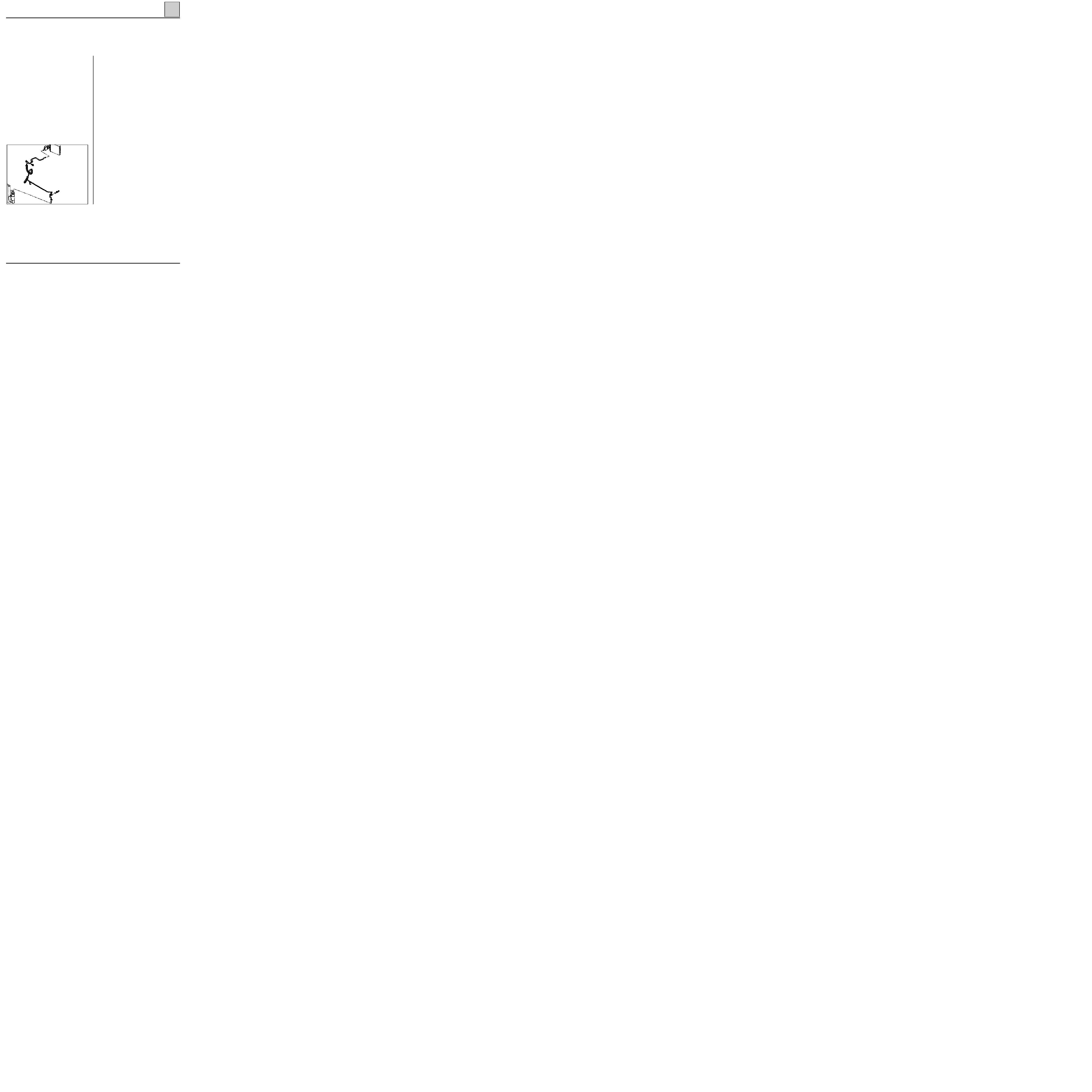
Connecting pipes
62
PRO62.4
Disconnect the battery.
Drain the R134a coolant circuit using the filling
equipment.
LOW PRESSURE PIPE
REMOVAL
Remove the mounting bolt on the pressure relief
valve.
Fit plugs to the pressure relief valve and the pipe.
Remove the mounting bolt on the compressor.
Fit plugs to the compressor and the pipe.
Unscrew the pipe retaining lug.
Remove the low pressure pipe.
REFITTING
Proceed in the reverse order to removal.
Check the condition of the seals and lubricate
them with
P.A.G. SP 10
oil.
When changing a pipe, add 10 ml of SP 10 oil or
when a pipe bursts (rapid leak), add 100 ml.
Create a vacuum, then fill the R134a coolant cir-
cuit using the filling equipment.
NOTE:
- Pipes to compressor
retaining bolt:
2.1 daN.m
- Pipes to pressure relief valve
retaining nut:
0.8 daN.m
- Pipes to condenser
retaining bolt:
0.8 daN.m
62-57

AIR CONDITIONING
Connecting pipes
62
Disconnect the battery.
Drain the R134a coolant circuit using the filling
equipment.
PRO62.5
NOTE:
the front bumper must be removed on the
version fitted with the E7J engine, in order to re-
move the cut off (1) retaining bolt.
COMPRESSOR-CONDENSER HIGH PRESSURE PIPE
REMOVAL
Remove the mounting bolt on the compressor.
Fit plugs to the compressor and the pipe.
Remove the mounting bolt on the condenser.
Remove the pipe.
Fit plugs to the condenser and the pipe.
REFITTING
Proceed in the reverse order to removal.
NOTE:
When refitting this connecting pipe to the
compressor, it is essential to fit all the bolts and
then bring them into contact before torque tigh-
tening them. The aim is to ensure that the pipe is
positioned correctly so that it is not damaged at
the cut off (1).
Check the condition of the seals and lubricate
them using
P.A.G. SP 10
oil.
When changing a pipe, add 10 ml of SP 10 oil or
when a pipe bursts (rapid leak), add 100 ml.
Create a vacuum, then fill the R134a coolant cir-
cuit using the filling equipment.
62-58
AIR CONDITIONING
Connecting pipes
62
Disconnect the battery.
Drain the R134a coolant circuit using the filling
equipment.
PRO62.6
DEHYDRATION CANISTER-PRESSURE RELIEF
VALVE HIGH PRESSURE PIPE
REMOVAL
Detach the pipe from its mountings.
Disconnect the pressure sensor connector.
Remove the mounting bolt on the pressure relief
valve.
Fit plugs to the pressure relief valve and the pipe.
Remove the mounting bolt on the dehydration ca-
nister.
Fit plugs to the dehydration canister and the pipe.
Remove the pipe.
REFITTING
Proceed in the reverse order to removal.
Check the condition of the seals and lubricate
them using
P.A.G. SP 10
oil.
When changing a pipe, add 10 ml of SP 10 oil or
when a pipe bursts (rapid leak), add 100 ml.
Create a vacuum, then fill the R134a coolant cir-
cuit using the filling equipment.
NOTE:
- Pipe to dehydration canister
retaining bolt:
0.8 daN.m
- Pipe to pressure relief valve
retaining nut:
0.8 daN.m
62-59
AIR CONDITIONING
Electrical control
62
13827R
• EVAPORATOR SENSOR (depending on assem-
bly)
REMOVAL
Disconnect the battery.
Remove:
- the windscreen wiper arms,
- the air inlet grille,
- the evaporator protector in the plenum cham-
ber.
Disconnect the evaporator sensor connector and
the air recirculation motor connector.
Free the wiring from its fasteners.
Remove the evaporator sensor.
REFITTING
Proceed in the reverse order to removal.
Ensure that the sensor is correctly positioned on
its seat on the evaporator.
• 0.28
Ω
FAN ASSEMBLY SPEED RESISTOR (2)
This is secured to the engine cooling fan support.
•
RECIRCULATION MOTOR
It is only possible to gain access to the recircula-
tion motor following removal of the air blower
unit (refer to the relevant section) and therefore
the evaporator assembly.
•
PRESSURE SENSOR
The pressure sensor (1) is located next to the
condenser on the pressure relief valve-
dehydration canister high pressure pipe.
All work on the pressure sensor can be carried out
without draining the coolant circuit. It is secured
to a "SKRADER" valve.
Tightening torque: 0.8 daN.m.
This pressure sensor is fitted with seal. Check that
it is in good condition on refitting and lubricate it
using
P.A.G. SP 10
oil.
62-60
AIR CONDITIONING
Computer
62
15-way connector (A)
13825R
Track
Description
1
Not used
2
AC operating information
3
Recirculation on/off
4
AC computer earth
5
+ 12 V accessories (fan assembly fuse)
6
+ 12 V after ignition (brake fuse)
7
Not used
8
Not used
9
Not used
10
Not used
11
Not used
12
Not used
13
Not used
14
Not used
15
Not used
62-61

AIR CONDITIONING
Computer
62
30-way connector (B)
Track
Description
1
+ 12 V after ignition (brake fuse)
2
Compressor control
3
L diagnostic information
4
Fan assembly voltage information
5
Not used
6
K diagnostic information
7
Not used
8
TDC information
9
Coolant pressure sensor
10
Coolant pressure sensor
11
Coolant pressure sensor signal
12
Evaporator sensor (depending on
assembly)
13
Power absorbed information (when the
compressor cuts in)
14
Not used
15
Not used
16
+ 12 V after ignition (brake fuse)
17
Compressor control
18
AC cut off information
19
Not used
20
AC fast idle information
21
Not used
22
Fan assembly low speed control
23
Fan assembly high speed control
24
Not used
25
Not used
26
AC recirculation motor
27
AC recirculation motor
28
Not used
29
Evaporator sensor (depending on
assembly)
30
Not used
62-62
Document Outline
Wyszukiwarka
Podobne podstrony:
MR 325 KANGOO 3
MR 325 KANGOO 8
MR 325 KANGOO 0
MR 325 KANGOO 3
MR 325 KANGOO 8
MR 325 KANGOO 0
MR 326 KANGOO 7
MR 326 KANGOO RX4 1
MR 326 KANGOO 6
MR 326 KANGOO 5
MR 326 KANGOO GV 4
więcej podobnych podstron