
EAGLE 4.0
for Linux
â
and Windows
â
Schematic - Layout - Autorouter
Tutorial
CadSoft Computer, Inc.
www.cadsoftusa.com
Copyright © 2000 CadSoft
All Rights Reserved

If you have any questions please feel free to contact us:
USA and other countries:
Phone:
+1 (561) 274 8355, USA also: 1-800-858-8355
Fax:
+1 (561) 274 8218
Internet:
www.cadsoftusa.com
Email:
Info@cadsoftusa.com
Germany and other European countries:
Phone:
+49 (0)8635 6989-10
Hotline:
+49 (0)8635 6989-30
Fax:
+49 (0)8635 6989-40
Internet:
www.cadsoft.de
Email:
Info@cadsoft.de
And remember that we offer a free hotline for our customers!
Copyright 2000 CadSoft Computer, Inc. All rights reserved worldwide
No part of this publication may be reproduced, stored in a retrieval system, or
transmitted, in any form or by any means, electonic, mechanical, photocopying,
recording, scanning, digitizing, or otherwise, without the prior consense of
CadSoft.
Windows is a registered trademark of Microsoft Corporation.
Linux is a registered trademark of Linus Torvalds.

Table of Contents
1 What to expect from this Manual
7
2 System Requirements
7
3 Features of EAGLE
8
Professional Version
8
General
8
Layout Editor
8
Schematic Module
8
Autorouter Module
9
Standard Edition
9
Light Edition (Freeware)
9
4 Installation and Program Start
10
Windows
10
Linux
10
5 Individual EAGLE Setup
10
6 The Concept of the EAGLE User Interface
11
7 Typographic Conventions
11
Selecting Menu Items
11
Mouse Click
11
Several Input Alternatives
12
Use of Key Combinations
12
Command and Parameter Input via the Command Line
12
8 Control Panel
15
EAGLE Files
16
EAGLE Projects
16
9 Load File and Select Monitor Zoom
17
10 Selecting Layers for Display
18
11 Setting up Grid and Unit
18
12 Wires, Circles, Arcs, Rectangles, and Text
19
The WIRE Command
19
Changing Line Width
20
Change Object to another Layer
20
3
EAGLE-Tutorial

Undo/Redo Function
21
The CIRCLE Command
21
The ARC Command
21
The RECT Command
22
The TEXT Command
22
Special Text Variables
23
13 Using Libraries
23
The ADD Command
23
The USE Command
25
The INVOKE Command
25
14 Drawing a Schematic
26
Grid
26
Adding a Frame to a Schematic
26
Adding and Changing Text
27
Entering a Schematic
28
The NET Command
30
The NAME Command
30
The LABEL Command
30
The DELETE Command
31
The JUNCTION Command
31
The SHOW Command
31
The MOVE Command
32
History Function
32
Completing the Schematic
33
The SMASH Command
33
The VALUE Command
34
The Electrical Rule Check (ERC)
34
Generating a Board from a Schematic
34
The BUS Command
35
15 Function Keys
36
16 Automatic Forward&Back Annotation
36
17 Designing a PC Board
37
4
EAGLE-Tutorial

Designing a Board without a Schematic
37
Defining Board Shape
37
Placement Grid
38
Placing Components
38
Placing SMD Packages
38
Providing Names
39
Providing Values
39
Defining Signals
39
Defining Signal Classes
40
Creating a Board from a Schematic
40
Generating a Board File
40
Component Placement
41
Autorouter: A Brief Example
41
Routing Manually
42
Board Changes
42
Further Usage of the Layout Editor
43
DISPLAY Command
43
MOVE Command
43
GROUP Command
43
SPLIT Command
44
CHANGE Command
44
ROUTE Command
45
RIPUP Command
45
SHOW Command
45
Refresh Screen
45
Undo/Redo Function
46
Inner Layers
46
Supply Layers
46
Copper Pouring
47
18 Autorouter
48
19 Design Rule Check
49
20 Libraries
50
5
EAGLE-Tutorial

Resistor Package
50
Resistor Symbol
52
Resistor Device
52
21 Output of Drawings and Manufacturing Data
55
Output a Schematic with the PRINT Command
56
Generating Gerber Data with the CAM Processor
56
22 Data Exchange with EAGLE User Language
57
23 Script Files - Flexible Input Interface
57
6
EAGLE-Tutorial

1 What to expect from this Manual
This tutorial provides a basic introduction to the EAGLE PCB-Design
Package.
It covers the use of the EAGLE Schematic Editor, Layout Editor, and
Autorouter. This guide will lead you through the program in the natural
order, starting with the Schematic Editor module and working through to
board design and autorouting. You will benefit most by going through the
entire document.
You should be familiar with the use of the basic functions of your operat-
ing system. Expressions like enlarge the editor window will be used without
further explanation.
Having completed this tutorial you should be able to start working on a se-
rious project. While creating your initial designs, however, you should fre-
quently use the help function and the EAGLE Reference Manual to learn
more about specific details. Only then will you be able to take full advan-
tage of EAGLE’s capabilities.
You will learn how to use most of the program commands, although not all
of the features which make EAGLE so powerful and flexible are discussed
in this introduction — for example the possibilities of the SET, SCRIPT,
and RUN commands (see help).
Before you begin you should consult the README file and the files with
the extension *.txt in eagle/doc.
Although this tutorial is based on the Windows version of EAGLE, the dif-
ferences to Linux are minimal.
2 System Requirements
EAGLE is a powerful graphics editor for designing PC-board layouts and
schematics. In order to run EAGLE the following hardware is required:
• IBM-compatible computer (486 and above) with
• Windows 95/98, Windows NT/2000 or
• Linux based on kernel 2.x, libc6 and X11 with a minimum color
depth of 8 bpp,
• a harddisk with a minimun of 50 Mbyte free memory,
• a minimum graphics resolution of 1024 x 768 pixels (800 x 600 with
minor restrictions possible),
• preferably a 3-button mouse.
7
EAGLE-Tutorial

3 Features of EAGLE
Professional Version
General
• maximum drawing area 64 x 64 inches
• resolution 1/10.000 mm (0.1 microns)
• mm or inch grid
• up to 255 layers, user definable colors
• command files (Script files)
• C-like User Language for data import and export
• simple library editing
• library browser with powerful search function
• support of technology feature (e.g. 74L00, 74LS00..)
• generation of graphics output as well as manufacturing and testing
output with the CAM processor or the help the User Language
• printouts via the OS's printer drivers
• partlist generation with database support (bom.ulp)
• Drag&Drop in the Control Panel
• automatic backup function
Layout Editor
• full SMD support
• full multilayer support (16 signal layers)
• Design Rule Check for board layouts (checks e.g. overlaps,
measures of pads or tracks)
• copper pouring (ground plains)
• package variants support
Schematic Module
• up to 99 sheets per schematic
• Online-Forward&Back Annotation between schematic and board
• automatic board generation
• automatic generation of supply signals
• Electrical Rule Check (error check in the schematic and consistency
check between schematic and layout)
8
EAGLE-Tutorial

Autorouter Module
• fully integrated into basic program
• uses the layout's Design Rules
• change between manual and automatic routing at any time
• ripup&retry algorithm
• user-definable strategy by cost factors
• routing grid down to 0.02 mm (about 0.8 mil)
• no placement restrictions
• up to 16 signal layers (with user definable preferred directions)
• up to 14 supply layers
• takes into consideration various signal classes (wire width,
minimum distances)
Standard Edition
The following restrictions apply to the Standard Edition in the Layout
Editor:
• The layout area is restricted to a maximum of 160 x 100 mm
(about 6.3 x 3.9 inches). Outside this area it is not possible to place
packages and draw signals.
• A maximum number of 4 signal layers are allowed (top, bottom,
and 2 inner layer).
Light Edition (Freeware)
The following restrictions apply to the EAGLE Light Version, which is
available as Freeware (for testing and evaluation):
• The board area is restricted to 100 x 80 mm (about 3.9 x 3.2 inches).
Outside this area it is not possible to place packages and draw
signals.
• Only two signal layers can be used (no inner layers).
• A schematic can consist of only one single sheet.
Larger layouts and schematics can be printed with the smaller editions. The
CAM processor can generate manufacturing data as well.
9
EAGLE-Tutorial

4 Installation and Program Start
Windows
Insert the media into the CD-ROM drive. Select the desired menu item di-
rectly in the CD-ROM start window.
If the start window does not automatically appear, double-click on the
CD-ROM symbol in My Computer.
Follow the instructions on the screen.
For the Freeware installation you do not need a User License Certificate.
Answer the question for a valid license by clicking Run as freeware.
If you decide to uninstall EAGLE, use the unInstallShield program which
will be installed along with the EAGLE program.
The EAGLE CD-ROM supplies a playable Freeware. You can start it with-
out installing it on your harddisk. But there are some minor restrictions
due to the fact, that EAGLE can't write files on the CD-ROM.
Linux
Insert the CD and mount the CD-ROM drive.
Choose the corresponding directory (/english/linux/install) and read the
installation notes in the README file. While installing the program you
will be asked if you want to run EAGLE as Freeware or as a licensed ver-
sion. Choose Run as freeware, if you don't have a valid license.
The EAGLE CD-ROM supplies a playable Freeware. You can run it from
CD-ROM directly. Therefor you have to mount the CD-ROM drive as
'executable'. But there are some minor restrictions due to the fact, that
EAGLE can't write files on the CD-ROM.
5 Individual EAGLE Setup
Apart from the basic installation, EAGLE allows the user to customize cer-
tain program features, such as the configuration of menus, function keys,
or screen colors. A lot of these settings can be made in the Options menu in
the Control Panel or in one of the editor windows.
In the special command file (script file) eagle.scr preset values for the Sche-
matic, Layout, and Library Editors can be entered in the form of EAGLE
commands. Those who would like to use these possibilities should get ac-
quainted with the EAGLE command language. The command syntax is de-
scribed in the EAGLE help.
10
EAGLE-Tutorial

The user interface can be set individually. Click the Options/User interface
menu in the Control Panel. The tutorial presupposes that you are using the
default settings.
Additional information concerning configuration can be found in the help
function. See the items SET, ASSIGN, User Interface, CHANGE, and
Project.
6 The Concept of the EAGLE User Interface
Internally, EAGLE has been set up in such a way, that any action is initi-
ated by a command string. Normally the user activates these commands by
clicking on menu items or toolbar icons. Values are normally entered into
appropriate fields.
The knowledge of the internal command language is not necessary to suc-
cessfully design schematics and boards with EAGLE. However, this con-
cept offers further possibilities which make EAGLE a very flexible tool:
Any command, for instance, can be entered in text format via the com-
mand line or can be read from a file. Furthermore, command strings can be
assigned individually to function keys (ASSIGN command). This enables
the user e.g. to execute command sequences with a key stroke or a few
mouse clicks (see SCRIPT command).
7 Typographic Conventions
Selecting Menu Items
The character
⇒
means, that a menu selection is to be made. For example
⇒
File/Save
means: click the File menu with the left mouse button and next click Save.
Mouse Click
Actions to be carried out with a click of the left mouse button are repre-
sented with a dot. For example:
•
MOVE and F1
means: click the MOVE command with the left mouse button and then
press the function key F1.
Actions to be carried out with a double click of the left mouse button are
represented with two dots. For example
11
EAGLE-Tutorial
• •
linear.lbr
means: select linear.lbr with a double click of the left mouse button from
the menu.
Several Input Alternatives
EAGLE commands can be entered via keyboard, by clicking icons or by
clicking menu items.
The following actions, for example, will execute the MOVE command:
• Clicking the icon
• Typing MOVE in the command line, followed by the Enter key
• Pressing the function key F7 which is assigned to the MOVE
command
• Selecting the menu item
⇒
Edit/Move
In this tutorial we will mainly work with the toolbars. For the sake of clar-
ity the commands are show as text:
•
MOVE
means: click the MOVE icon
Use of Key Combinations
A + character indicates that the first key is held down while pressing the
second key. For example:
Alt+F1
The Alt key is held down while pressing F1, then release both keys.
Command and Parameter Input via the Command Line
Actions which need to be terminated with the enter (i.e. return) key are
symbolized with the character
←
. For example
USE
←
means: type USE and next press the Enter key.
Anything that is to be typed exactly as it appears, will appear in the text as
follows:
CHANGE WIDTH 0.024
←
Normally EAGLE does not differentiate between upper and lower case
characters. Therefore you can enter the above command as
12
EAGLE-Tutorial
change width 0.024
←
You may abbreviate the key words. The above input may therefore be sim-
plified to
cha wid 0.024
←
In this tutorial, however, the full commands are used.
The following figures show which commands are activated with the various
toolbar icons. Additional help is offered by the Bubble Help text which ap-
pears as soon as the mouse cursor is positioned on an icon for a certain
time. This text shows the command name.
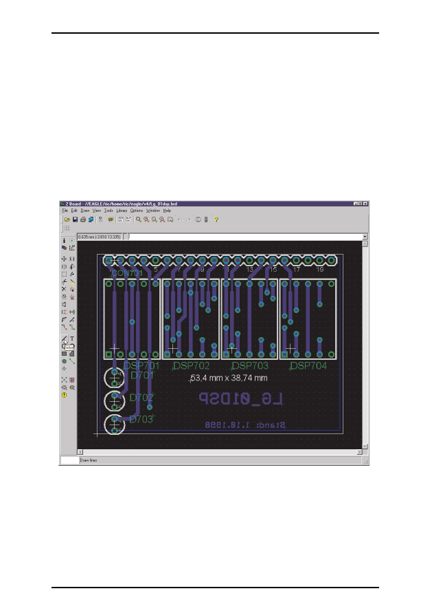
The Layout Editor window
From top to bottom: title, menu bar, action toolbar, dynamic parameter
toolbar and coordinates display with command line. On the left the com-
mand toolbar. The Bubble Help text describes the WIRE icon. The status
bar below shows a short description of the current command.
13
EAGLE-Tutorial
14
EAGLE-Tutorial
Info
Display
Move
Mirror
Group
Cut
Delete
Name
Smash
Pinswap
Split
Wire
Circle
Rectangle
Bus
Junction
ERC
Show
Mark
Copy
Rotate
Change
Paste
Add
Value
Gateswap
Invoke
Text
Arc
Polygon
Net
Label
Info
Display
Move
Mirror
Group
Cut
Delete
Name
Smash
Pinswap
Split
Route
Wire
Circle
Rectangle
Via
Hole
Ratsnest
ERC
Errors
Show
Mark
Mirror
Rotate
Change
Paste
Add
Value
Replace
Optimize
Ripup
Text
Arc
Polygon
Signal
Auto
DRC
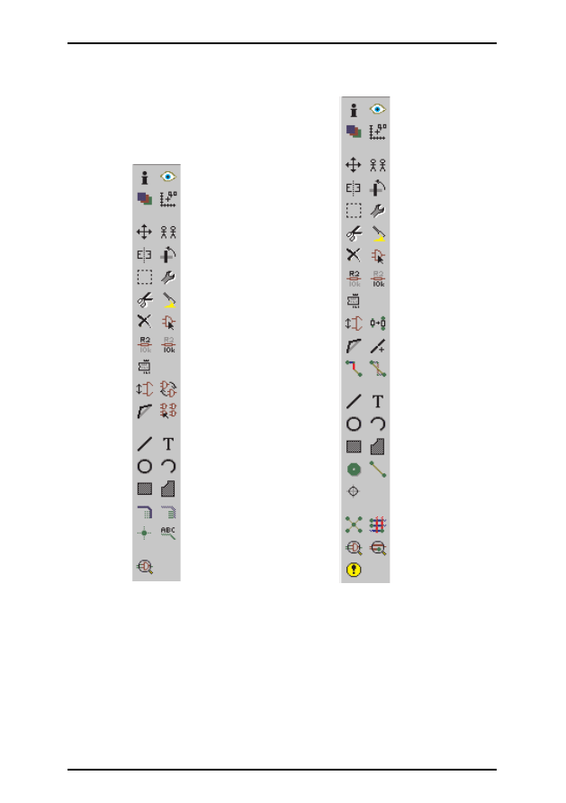
Command toolbar of the Schematic Editor (left) and the Layout Edi-
tor (right)
8 Control Panel
After starting EAGLE, the Control Panel will be opened. It allows you to
load and save projects as well as to setup certain program parameters. Right
mouse click to an entry in the Projects branch of the tree view opens a con-
text menu that allows to start a new project.
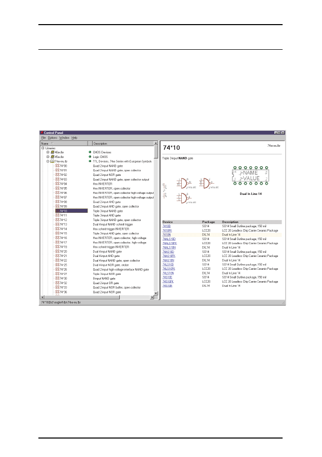
The tree view allows a quick survey of EAGLE's libraries. Double-click an
entry in the Libraries branch. Now the contents of the library is displayed.
Selecting an object shows a short descriptive text on the right.
Control Panel: Preview of the library contents
Here you get an overview of User Language programs, Script files, and
CAM jobs. Try selecting various entries. On the right you will get the re-
ferring description.
The Control Panel supports Drag&Drop. A right mouse click on any entry
in the tree view opens a context menu that offers options like print, open,
copy, etc.
15
EAGLE-Tutorial

EAGLE Files
The following table lists the most important file types that can be edited
with EAGLE:
Type
Window
Name
Board
Layout Editor
*.brd
Schematic
Schematic Editor
*.sch
Library
Library Editor
*.lbr
Script File
Text Editor
*.scr
User Language Program Text Editor
*.ulp
Any text file
Text Editor
*.*
The Linux version only recognizes lower case letter file extensions!
EAGLE Projects
Lets create a new project first. After starting the program, first
•
the +
character of the Projects path, then the + character of the entries examples
and tutorial in the tree view. The contents of the tutorial directory appears.
•
tutorial with the right mouse button. Select the option New Project in the
popup menu. Name the new project MyProject, for example.
This way you are creating a subdirectory of tutorial that is named MyPro-
ject. This directory will contain all data files that belong to your project. Of
course you may define additional subdirectories.
To define the path where your project directories will be stored, click
⇒
Options/Directories and enter it in the Projects field.
A right mouse click on the project entry and you can open new schematics,
layouts and libraries. Each project directory contains a file named eagle.epf
which stores project-specific settings, window positions etc.
The currently active project is checked (green) in the Control Panel. After
starting the program again the previous situation will be restored. The last
used project and other user-specific settings are saved in the file
~
/.eaglerc
(Linux) or eaglerc.usr (Windows).
Before starting the following examples we want to copy the files demo1.sch
,
demo2.sch, and demo2.brd into the directory MyProject.
Press the Ctrl key, click the desired file and drag it to the tutorial entry. Re-
lease the mouse button now. Repeat this for the other files.
Now open the schematic file demo1.sch with a double click.
16
EAGLE-Tutorial
If you end the program with Alt+X and start it again, you will get the pre-
vious settings and editor windows.
9 Load File and Select Monitor Zoom
Now let us start doing some exercises. Start EAGLE, and wait until the
Control Panel appears.
Expand the entry Projects/examples/tutorial/MyProject of the tree view.
Now load the demo2.brd file. You can do this either by
• •
the entry de-
mo2.brd, or by selecting the file from the menu
⇒
File/Open/Board. The
schematic with the same name will be loaded along with the board.
Enlarge the board editor window.
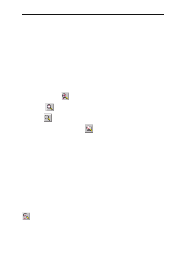
Now click the icon
to zoom into the drawing.
By clicking
the drawing will be shown in full size to fit your screen.
A click on
will zoom out.
The command controlled by the
icon is more versatile than in other
programs. Click it, and then mark a rectangular area by dragging the mouse
cursor while the left mouse button is pressed. Then release the mouse but-
ton, just as you are used to from other programs. The marked area will now
be displayed.
If you want to select a new center with the same zoom factor, simply click
the same icon, mark the center with a click and finally click on the traffic
light icon in the action toolbar.
If you want to select a new center and a new zoom factor simultaneously,
click on the same icon. Three mouse clicks will give you the desired result:
the first click will define the new center and both last clicks will define the
zoom factor. If the third point is further away from the first, the program
will zoom into the drawing and vice versa. Try it to find out how it works.
During certain actions it may happen that objects in the drawing disappear
or get corrupted. In this case refresh the screen by clicking the Redraw icon
(also F2 possible).
If you want to move the selected window, press the Ctrl key while moving
the mouse.
Further possibilities can be found on the help pages of the WINDOW
command. These can be called up by simply typing in the command line:
17
EAGLE-Tutorial

HELP WINDOW
←
10 Selecting Layers for Display
EAGLE-Drawings contain objects in different drawing layers. In order to
obtain a useful result several layers are combined for the output. For exam-
ple, the combination of Top, Pad, and Via layers is used to generate a film
for etching the component side of the printed-circuit board. Consequently
the combination of Bottom, Pad, and Via layers is used to generate the film
for the solder side of the board. The Pad layer contains the through-holes
for the component connections and the via layer contains the via-holes
which are needed when a signal track changes to another layer.
Load the board demo2.brd using the menu File/Open/Board and click in
the command toolbar on the icon for the DISPLAY command (look at the
toolbar layout on the previous pages). The marked layers are currently dis-
played. By clicking on the layer number the display of each layer can be
switched on or off. The All and None buttons switch on or off all layers.
By selecting/deselecting layer 21 tPlace (silk screen upper side), the layers
23 tOrigins, 25 tNames, 27 tValues, and 51 tDocu are selected/deselected,
too. The same applies to layer 22 bPlace (silk screen bottom side).
Very important: Components on layer 1 Top can only be moved or se-
lected in the drawing if layer 23 tOrigins is on. The same applies to compo-
nents on layer 16 Bottom and the layer 24 bOrigins.
Please consult the help page of the LAYER command for the meaning of
the different EAGLE layers.
11 Setting up Grid and Unit
Schematics should always be drawn on a grid of 0.1 inches since the librar-
ies are defined this way.
The grid for boards is determined by the components used and by the com-
plexity of the board.
Grid and unit are setup with the GRID command by clicking on the GRID
icon
in the parameter toolbar. All values are given in the currently se-
lected unit. Please consult the help pages of the GRID command for de-
tailed information.
18
EAGLE-Tutorial
12 Wires, Circles, Arcs, Rectangles, and Text
Wires, circles, arcs, rectangles, and text are created with the WIRE,
CIRCLE, ARC, RECTANGLE and TEXT commands. On one hand these
objects serve as pure drawing elements for symbols, packages, frames etc.,
and on the other hand they can perform special functions, such as the defi-
nition of restricted areas.
First a new schematic file is to be created. Close all of the editor windows
and select
⇒
File/New/Schematic
from the Control Panel.
A new file with the name untitled.sch is now created. Normally you should
never save a file with the name untitled, but should use
⇒
File/Save as to
choose a different name. However, in this tutorial no file is to be saved at
all.
Now enlarge the editor window.
The WIRE Command
The WIRE command is used to draw lines.
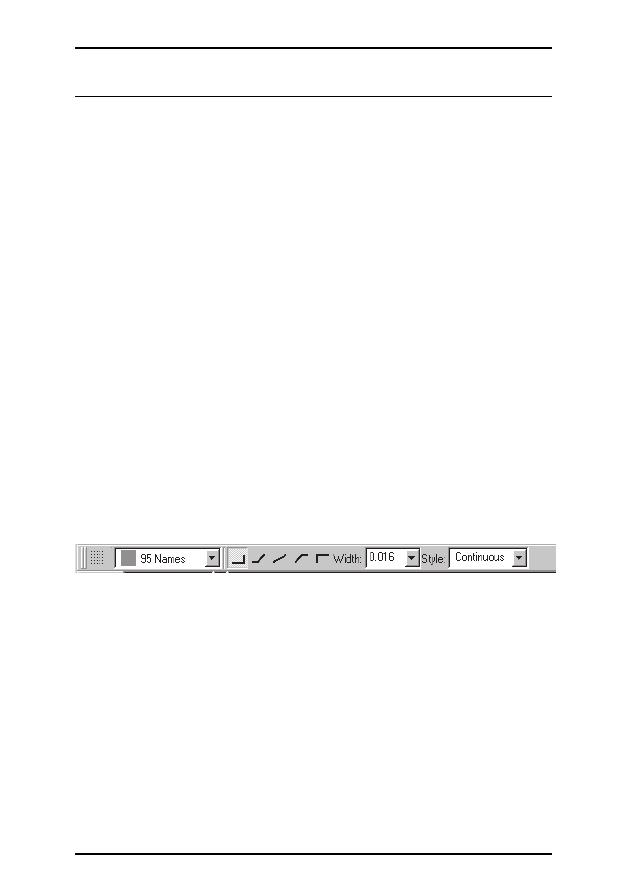
Click the WIRE command in the command toolbar. All parameters for this
command can be set up in the parameter toolbar. Next select layer 95,
Names, from the layer-selection combo box. In this layer a rectangular line
is to be drawn.
Parameter of the WIRE command
Define the starting point by a click on the left hand mouse button. Move
up the cursor slightly to the right and press the right hand mouse button a
few times. Please observe how the connection is shown in different diago-
nal and orthogonal modes. When the connection is displayed in a square
angle, press the left hand button to fix its position. Now move the cursor
to the starting point and
• •
to drop the line. Now you should be able to
see a rectangular outline. As observed before, an angle between wire seg-
ments can be created by clicking the right hand mouse button. This is more
effective than using the symbols in the parameter toolbar.
19
EAGLE-Tutorial

In the Layout Editor:
If the lines are placed on the board layers Top, Bottom, or Route2..15
EAGLE treats them as electrically conducting tracks. Wires are also used to
create board outlines. Let’s start using this command.
Changing Line Width
As long as the WIRE command is active, you can select the line width from
the combo box in the parameter toolbar or type in a specific value, separate
for each segment.
To change the line width of an existing object,
•
CHANGE icon in the command toolbar and a popup menu will open
up.
•
WIDTH icon and a further popup menu will show up where the
present value is marked.
Select the desired value by a click of the mouse, then click the object to be
changed.
To change a line width to a value that is not shown the menu of the
CHANGE command, you can use the command line to type in the value,
for example:
CHANGE WIDTH 0.017
←
and then click on the selected wire segment.
To change the wire style
•
CHANGE and
•
Style. Select the style and
•
the
wire you want to change.
Change Object to another Layer
To move an object, for example a wire segment, to another layer
•
CHANGE
•
LAYER
Select the target layer, for example 94 Symbols, by
•
. Then
•
OK, and then
•
on the selected object(s). Note that some objects, such as bus or net lines,
cannot be moved to another layer as they have a special meaning.
20
EAGLE-Tutorial
Attention: Do not use the WIRE command to draw net or bus lines in
schematics - use NET or BUS instead!

Undo/Redo Function
One of the most useful features of EAGLE is the unlimited Undo func-
tion. Click the left icon as many times as you want to undo previous ac-
tions. Use the right icon to redo the actions which have been cancelled by
undo.
The CIRCLE Command
To activate CIRCLE, which is used to draw a circle,
•
CIRCLE
EAGLE requires two mouse clicks to define a circle. The first click sets the
center of the circle and the second click defines the radius.
Place the cursor at any grid point and
•
. Drag the cursor several grid points
to the right. When the circle has the diameter you want,
•
to fix it and ter-
minate the command. The line width of the circle can be changed as de-
scribed before for wires. A circle with line width 0 will be filled.
To find out more about the CIRCLE command press F1 as long as the
command is activated or type
HELP CIRCLE
←
.
To cancel a command, click the stop sign icon or activate another com-
mand. Pressing the Esc key generally unlocks an object from the cursor.
The ARC Command
To activate the ARC command, which is used for drawing arcs,
•
ARC
An arc is defined with three mouse clicks: the first click defines the start
point, the second the diameter and the third the end point.
Place the cursor at the desired starting point and
•
. Now move the cursor
some grid units to the right but remain on the same Y-coordinate. A circle
appears which shows the diameter of the arc.
•
and the circle will become
an arc. Now you can change the direction of the arc with the right mouse
button. Click several times with the right button and you will see what is
meant. You can also enlarge or minimize the arc by moving the mouse. Af-
ter reaching the desired form,
•
to fix the arc.
Practice by drawing some arcs. Use the help function to find out more
about the ARC command.
21
EAGLE-Tutorial

The RECT Command
To activate the RECT command, used for creating filled rectangles,
•
RECT
To define a rectangle two mouse clicks are required: The first one will de-
termine one corner and the second determines the position of the opposite
corner.
Move the cursor to the point where a corner of the rectangle should be and
•
. Move the cursor slightly to the right and up. When the rectangle has
reached the desired size,
•
to fix it. The rectangle is filled with the color of
the layer in use.
Use the help function to find out more about the RECT command.
The TEXT Command
To activate the TEXT command, used for placing text,
•
TEXT
Now type the desired text and
•
OK. Then place the text with
•
. A copy of
the same text is now attached to the cursor. To stop placing text simply
click the next command icon. For placing a different text, type the text and
terminate it with the Enter key. The text will show up in the command line.
Texts containing spaces or a semicolon have to be enclosed in single
quotes, like this one:
'This is a text'
To change the text font:
•
CHANGE
•
FONT
EAGLE supports a vector, a proportional, and a fixed font.
To change the size of a text:
•
CHANGE
•
SIZE
•
Value in the menu
and
•
lower left corner of the text. At a rotated text the point of origin can
move to its upper right corner. A text is always displayed so that it can be
read from the front or from the right.
22
EAGLE-Tutorial

To change a text
•
CHANGE
•
TEXT
and
•
at the point of origin of the text, then edit the text and
•
on OK.
Using
•
CHANGE
•
RATIO
you can change the line width in a text in relation to the height of the vec-
tor font.
See help page for more information about TEXT and CHANGE.
Special Text Variables
If you place the text
>SHEET
this string will be substituted with the current sheet number, e.g. 1/1.
EAGLE offers a number of similar text variables, e.g. for date/time which
reflect the latest change in the file (>LAST_DATE_TIME) or the drawing
output (>PLOT_DATE_TIME). Library parts are defined with text vari-
ables for the name (>NAME) and the value (>VALUE) of a component.
Use text variables only in libraries.
13 Using Libraries
EAGLE comes with a lot of library files that contain through-hole and sur-
face mount devices. The tree view in EAGLE's Control Panel and the file
library.txt (in eagle/doc) offer detailed information about the contents of
the libraries.
In this section you will learn how to insert schematic symbols into a draw-
ing and how to use them.
Open a new schematic to start with a blank drawing area
⇒
File/New/Schematic.
The ADD Command
To select symbols from a library,
•
ADD in the command toolbar, and a
window pops up.
Now you can enter on or more search patterns in the Search field. You may
use the name of a device or any word of the device description. Wild cards
23
EAGLE-Tutorial

like * and ? are allowed.
We want to place, for example, the device 74LS00. Enter in the Search field:
74*00* or 74LS00*
* is the wild card of the technology and/or the package variant. The search
result shows the device in various technologies and package variants. Select
the desired device and
•
OK. Now you can place it in the schematic.
Place the cursor slightly to the left of the display center and
•
. Move the
cursor to the right, and place a second gate with the next mouse click. Place
four gates around the center of the drawing area in this way.
Now place a fifth gate somewhere nearby. Please note that EAGLE has
named the first four gates IC1A..IC1D, whereas the fifth gate has been
named IC2A, since this gate requires a second IC.
If you now show the layer 93, Pins, either as described before or by typing
DISPLAY PINS
←
in the command line, further pin parameters are displayed in green. Zoom
in on the drawing, so that a gate is shown on a large scale. You will see that
the pins are marked as Input (In) or Output (Out), and that a number
shows the Swaplevel. A Swaplevel greater than 0 indicates that this pin can
be swapped with another pin of the same device which has the same
Swaplevel assignment (see command PINSWAP). A pin with a swaplevel
of 1, for example, can be swapped with any other pin that has a swaplevel of
1. Swaplevel 0 means that this pin cannot be swapped.
The layer 93, Pins, is not usually printed (PRINT command).
As long as the ADD command is still active, a gate symbol will be attached
to the cursor.
Now use the Zoom-in icon or the F4 key to view a larger portion of the
schematic on the display. Then press the Esc key to the selection window
of the ADD command.
Enter the following pattern in the Search field:
555N or 555*
Select the device 555N with
• •
, rotate it 180 degrees with two mousebut-
ton clicks, and place it somewhere on the drawing area with the left mouse
button.
Repeat this with other symbols. You will find out that the libraries contain
symbols drawn in the European and the American way. Choose whatever
you prefer.
While the ADD command is active, you can return to the ADD menu by
24
EAGLE-Tutorial

pressing the Esc key. Press the Esc key again and the command will be
cancelled.
Another way to place devices in the schematic is to drag them from the tree
view in the Control Panel into the Schematic Editor window. Arrange the
windows in a way that you can see both on the screen. Select, for example,
the device 555N from linear.lbr in the tree view (Libraries branch). Use
Drag&Drop to move the device into the Schematic Editor. If you select a
device that supports more than one package or technology variant, you will
be asked to select the variant in a menu before dropping it.
EAGLE, by default, assumes that all active components will be attached to the
same power source and ground. The power pins are therefore not shown, and
are automatically connected to the Power Source and Ground when generating
a board (unless the user connects them to other signals).
Most of the EAGLE library devices, which have only one VCC and one GND
pin, are defined so that the power pins, by default, are not visible. In some
cases it makes sense to make the power pins in an IC visible, as in the 555
stored in the linear library. In such a case connect the power pins with the ap-
propriate nets.
The help function in EAGLE offers information about further options of
the commands ADD and UPDATE concerning the update of library ob-
jects in schematic and layout with their respective parts of the current
libraries.
The USE Command
The default setting causes the ADD command to search in all libraries that
are available in the given libraries directories (
⇒
Options/Directories/Li-
braries in the Control Panel). You can exclude libraries from the search
function by clicking the green marker in the Control Panel's tree view,
Libraries branch. Green means in use, gray not used.
This is exactly the function of the USE command you can also type on the
command line. The syntax is described in the help function.
The INVOKE Command
The INVOKE command can be used to allow the connection of active
components to a power source other than VCC and GND. To demon-
strate its use
•
INVOKE
•
the gate IC2A
A popup menu appears.
25
EAGLE-Tutorial

• •
PWRN and the power pins for IC2 are attached to the cursor. You can
now place them anywhere with a
•
and connect them to any net.
Another feature of the INVOKE command allows you to alter the se-
quence of the reference designators before EAGLE automatically makes an
assignment. Assuming the INVOKE command is still active,
•
IC2A, and
the popup menu appears. The asterisk assigned to gate A indicates that the
gate has been used; those without an asterisk are available for use.
If you want IC2C to be placed before IC2B,
• •
C in the popup menu. The
menu closes, and IC2C is attached to the cursor to be placed with a
•
.
Once IC2C is placed, EAGLE will use up the remaining gates in that pack-
age before assigning an additional package.
If you want to place gates over more than one sheet, use the INVOKE
command on the new sheet and type in the element's name in the com-
mand line. Now the invoke menu pops up.
Don’t hesitate to experiment with different libraries and with placing and
rotating schematic symbols.
You can place devices in a drawing from as many libraries as you want. De-
vices are saved in the schematic or board files in their entirety. When passing
on a file, there is no need to supply the libraries with them.
14 Drawing a Schematic
In this section you will learn how nets and buses are used in a drawing. You
will then be able to create a schematic.
To create an empty schematic, open a new drawing and enlarge the editor
window.
Grid
The standard grid for schematics is 0.1 inches. Symbols should be placed on this
grid or a multiple of it, since otherwise it can happen that nets cannot be con-
nected to the pins.
Adding a Frame to a Schematic
As a start, select a drawing frame from the library frames.lbr, which con-
tains predefined frames in miscellaneous formats.
•
ADD, and enter the word letter or frame in the search field. Select a suitable
frame and
• •
for example LETTER_P. A frame which fits on a letter for-
mat page (portrait) is now attached to the cursor.
26
EAGLE-Tutorial

If you cannot see it completely, press function key F4 until it matches your
screen, then place it with a click of the left hand mouse button so that its
lower left corner is placed on the coordinates (X=0, Y=0).
Now a further frame is attached to the cursor. Click the icon with the stop
sign to terminate the ADD command. Press:
Alt+F2
to show the frame in full size or click the Zoom-to-fit icon in the action
toolbar.
Adding and Changing Text
You can add lines, text and other objects to predefined frames and text
fields in the library. Or you can design and save your own frames.
Variable texts, e.g. the project title or the revision number, can be inserted
directly in the Schematic Editor where you are now.
Frames are saved as symbols in the library, therefore it makes sense to
write the text in layer 94 Symbols.
Now bring the frame text field into the editor window so that it is com-
pletely visible. Next click the icon for the TEXT command and enter the
following text
CadSoft
After clicking the OK button, the text is attached to the cursor and can be
placed with the left mouse button. Move the text in the upper empty line
of the text field and place it with a
•
. A further copy of the text, which will
disappear as soon as another command is activated or the stop sign icon is
clicked, is still attached to the cursor.
If you did not define the size of the text while the TEXT command was ac-
tive, you can use the CHANGE command to set it to another value:
•
CHANGE
From the menu select:
•
SIZE
and a further window opens in which the presently selected text height is
shown.
•
0.15
and move the cursor to the lower left corner of the text CadSoft. Click
the left mouse button and the text height will be changed to 0.15 inches.
Just in case you would like to set a size not present in the CHANGE SIZE
menu, like. 0.17, simply type:
27
EAGLE-Tutorial

CHANGE SIZE 0.17
←
and then click the lower left corner of the text.
Practice manipulating texts by adding an address or a document number in
the text field.
TITLE: contains the file name in use (special text >DRAWING_NAME).
DATE: contains the date (special text >LAST_DATE_TIME).
Both fields are automatically filled with the actual data when the drawing is
saved, since the frames stored in the frames library have been defined with
the appropriate text variables.
Entering a Schematic
Now lets start drawing a schematic. We will be drawing the schematic
shown in the following figure, which you can use for reference. If you
don’t want to enter the whole schematic you can use the file demo1.sch
stored in the eagle/examples/tutorial directory.
Start by pressing ALT+F2 or clicking the Zoom-to-fit icon to fill the win-
dow with the drawing frame.
The schematic consists of the following elements:
Partlist:
Exported from demo1.sch at 29.09.2000 15.02.27
EAGLE Version 4.0 Copyright (c) 1988-2000 CadSoft
Part
Value
Device
Package
Library Sheet
C1
30p
C-EUC1206
C1206
rcl
1
C2
30p
C-EUC1206
C1206
rcl
1
C3
10n
C-EU025-025X050 C025-025X050 rcl
1
C4
47u/25V
CPOL-TAP5-45
TAP5-45
rcl
1
C5
47u
CPOL-TAP5-45
TAP5-45
rcl
1
D1
1N4148
1N4148
DO35-10
diode
1
IC1
PIC16F84AP
DIL18
microchip 1
JP1
PROG
PINHD-1X4
1X04
pinhead
1
JP2
APPL
PINHD-1X17
1X17
pinhead
1
Q1
XTAL/S
QS
special
1
R1
2.2k
R-EU_R1206
R1206
rcl
1
U1
78L05
78LXXZ
TO92
linear
1
Use the ADD command to place the listed devices. You can toggle the grid
on and off using F6, to help you locate the parts.
28
EAGLE-Tutorial
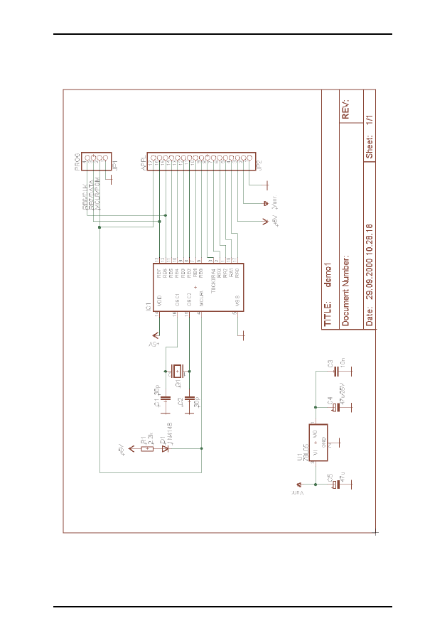
Schematic demo1.sch
29
EAGLE-Tutorial
Once you have placed the parts you can relocate them with the MOVE
command. Activate the MOVE command by clicking the appropriate icon
in the command toolbar, then move the cursor to the part you want to
move and
•
. EAGLE will highlight the part, to let you know that it is at-
tached to the cursor and ready to be relocated.
Relocate the part, and
•
to place it in its new location. The MOVE com-
mand is still active and ready to move the next part. Press the right mouse
button if you want to rotate a part.
When you have located the parts, start connecting them using the NET
command.
The NET Command
A net is only connected to a pin if it is placed on the connection point of
the pin. Display the layer 93, Pins, with the DISPLAY command to locate
these connection points. They are marked with a green circle.
EAGLE automatically names electrical connections (nets). In our example
demo1.sch the net lines at C5 pin +, U1 pin 3(VI), and JP2 pin2 have the
same name. The pins are connected to the same net, although the net lines
are not draw continuously.
As mentioned before, nets with the same name define an electrical connection.
The NAME Command
EAGLE automatically allocates names such as B$.. for buses, P$.. for pins
and N$.. for nets.
•
NAME and then
•
the net connected to IC1 pin OSC1 (16). A popup
menu shows the predefined name of the net. Type in
OSC1
and
•
OK. The net immediately now has this name.
The names of components and busses can be changed in the same way.
The LABEL Command
The LABEL command allows you to place bus or net names on a schematic
in any location.
•
LABEL, locate the cursor on the net MCLR/PGM and
•
.
30
EAGLE-Tutorial
Attention: Do not use the WIRE command!

The name of the net is attached to the cursor and you can place it in any lo-
cation. You can also rotate the label with the right mouse button. Locate
the label approximately as shown in the figure and
•
to fix its position
(near JP1 pin 2).
If net or bus names are changed, the relevant labels are also changed. Label
text is not changed with the CHANGE TEXT command but with the
NAME command.
CHANGE FONT or CHANGE SIZE changes the font or the text size.
The DELETE Command
You can delete objects with this command. If it is applied to nets, wires or
busses, a single segment is deleted at a time. To use this command,
•
DELETE in the command toolbar, take the cursor to the object that is to be
deleted, and
•
.
UNDO and REDO work here as well. GROUP, DELETE and a right
mouse click delete whole groups.
The JUNCTION Command
Dropping a net on another net line generates a connection between these
two nets. The connection will be represented by a junction, that will be set
automatically. Automatic setting of junctions can be switched off with the
option Auto set junctions (
⇒
Options/Set/Misc).
In this case the JUNCTION command is used to draw a connecting node
at the intersection of nets which are to be connected to each other.
•
JUNCTION and a node is attached to the cursor. Locate the node at the
junction of two net lines and
•
to fix it into place.
The SHOW Command
This is a good time to demonstrate the function of the SHOW command.
This command is used to show names and other details of elements and ob-
jects. Complete signals and nets can be highlighted, as well as components.
To show for example the net V+,
•
SHOW in the command toolbar then
move the cursor to the connection point of U1 pin VI (3) and
•
.
Please notice that EAGLE highlights the net wires and each pin connected
by this net, as well as the pin name of each part to which it is connected. In
addition, the signal is listed as
Net: V+
in the status bar.
31
EAGLE-Tutorial

While the SHOW command is active the net remains highlighted although
you are panning the window by pressing the Ctrl key and moving the
mouse or using the WINDOW command. Deactivate the SHOW com-
mand by clicking the stop sign icon and use WINDOW REFRESH (F2).
Now the objects are no longer highlighted.
To show an object with a specific name,
•
SHOW and type the name (for
example D0
←
) in the command line. You can subsequently type other
names without the need to reactivate the SHOW command. This way you
can mark one net after the other.
Do you wish to highlight several nets at the same time, enter in the com-
mand line:
SHOW RA4
←
SHOW RA3
←
SHOW RA2
←
The MOVE Command
In order to avoid mistakes when placing and moving nets you have to un-
derstand the following effects of the MOVE command:
No electrical connection will be generated if you move a net line over a pin
(using the MOVE command). On the other hand: if you move a pin over an-
other pin or over a net line, an electrical connection will be generated, and a
net line will be attached to the pin when the component is moved further. Re-
member the UNDO command if you want to detach the net line.
Check the connections with the SHOW command, as mentioned before.
Additional one can export a net or pin list with the EXPORT command.
History Function
With the keys up-arrow and down-arrow you can recall the last keyboard
instruction into the command line and execute it with the Enter key. The
Esc key will delete the command line.
Use Alt+F2 to show the whole schematic on the screen, then type:
SHOW R1
←
SHOW C1
←
SHOW IC1
←
Quit the SHOW command by clicking the stop sign icon. Redraw the
screen, e.g. with F2 and press the up-arrow and down-arrow keys several
times. As you can see, you can scroll through the list of the recently used
commands. As soon as the desired command appears in the command line
32
EAGLE-Tutorial

press the Enter key.
Completing the Schematic
Use the ADD command to add the remaining components and the sym-
bols for VCC, V+, and GND from supply.lbr (search pattern: supply).
Supply symbols represent the power signals in your schematic and cause
the ERC (Electrical Rule Check)to use special checks for them.
Remember that you can use the MOVE command to move objects around
and that you can rotate elements attached to the mouse with a right mouse
click.
Using the NET command, connect the pins of the components according
to the schematic and connect the supply symbols to the related pins. Use
the right mouse button to alternate between the orthogonal and diagonal
modes while using the NET command. Use
•
to fix a segment.
If you place a net exactly on a connection point, the net is terminated at
this location.
The SMASH Command
You will notice that when you rotate diodes and resistors from the hori-
zontal to the vertical position, their reference designators and value texts
rotate with the part. EAGLE provides a SMASH command that allows you
to MOVE and ROTATE the name and value texts independently of the
symbol.
To activate the command
•
SMASH
Locate the cursor on the diode symbol and
•
. This separates the text from
the symbol. Now click the MOVE icon, move the cursor to the name D1 for
the diode, and
•
.
The text selection point is marked as a cross and resides, depending on the
rotation, on the lower left or the upper right corner.
The name is now attached to the cursor. It can be moved to a better loca-
tion and rotated with the right mouse button. When you have rotated and
relocated D1,
•
to fix its location.
If you want to change the size of name and value texts which have been
separated from the part with the SMASH command, use the CHANGE
SIZE command (click the CHANGE icon and select Size from the menu).
33
EAGLE-Tutorial

The VALUE Command
EAGLE allows you to define or to change the value elements like resistors
or capacitors. In the case of ICs the value informs you about the element
type (e.g. 74LS00N).
•
VALUE
•
the resistor,
type the new value, 2.2k,
•
OK, and the new value is now displayed.
You can use the NAME command to change the names of resistors, capaci-
tors, ICs, nets and buses accordingly. You can change the net names but
you don’t have to, unless you want to get a descriptive netlist.
The Electrical Rule Check (ERC)
If you haven’t entered the complete schematic yourself you can now load
the file demo1.sch.
The ERC command is used to test schematics for electrical errors.
The results are warnings and error messages that are generated and written
into a file which has the same file name as the drawing but the extension
*.erc. This file is automatically displayed in a text editor window if mes-
sages were generated. To use the command click the ERC icon in the com-
mand toolbar.
Please note that the ERC can only discover possible error sources. It is up to
you to properly interpret the ERC messages!
If you want to learn more about the ERC command, type
HELP ERC
←
in the command line.
Generating a Board from a Schematic
After loading a schematic from which you would like to design a board,
click on the BOARD icon in the action toolbar:
A board file will be generated in which the packages are positioned next to
an empty board.
A further description follows in the chapter Designing a PC Board.
But now we want to introduce an other important command that is neces-
sary to design schematics first.
34
EAGLE-Tutorial

The BUS Command
Load the schematic bus.sch from the /eagle/examples/tutorial directory.
A schematic with a bus structure appears. A bus has to be drawn with the
BUS command. It is named automatically (B$1..).
A bus has no logical significance. It is a drawing element only. Logical con-
nections (nets) are only defined with the NET command. Nets with the
same name are identical even if they are on different pages of a schematic or
optically not connected.
The bus name determines the signals contained in the bus. In our example
the bus contains the signals VALVE0 to VALVE 11 and a signal named
EN. Therefore the bus has been named EN,VALVE[0..11] with the
NAME command.
The bus in our example has not been finished, yet. There are still some con-
nections to draw. Start to connect the following signals to IC7 by selecting
the NET command and clicking on the bus line:
EN
IC7 Pin 14 EN
VALVE0
IC7 Pin 16 INA
VALVE1
IC7 Pin 15 INB
VALVE2
IC7 Pin 10 INC
VALVE3
IC7 Pin 9 IND
•
NET in the commando toolbar and move the cursor over the bus, one grid
line over the pin IC7-14. The net connection to the bus must originate
from the bus and be drawn to the component pin, if you want to use this
convenient way to name it.
•
to set the starting point of the net, and a
popup menu will appear with the net names for the bus.
•
EN to select net
EN, and move the cursor to IC7-14, using the right mouse button to
change the line until it is drawn like the other net lines in this area.
•
the
pin's connection point to finish the net line.
Repeat this action for VALVE0 .. VALVE3.
Use the LABEL command to make the net names visible in the schematic.
If you want to cancel an action, click the UNDO icon, or use the F9 key.
Either by clicking on the REDO icon or by use of the F10 key you can per-
form the cancelled action once again.
Use the MOVE command to move individual bus segments. Select a seg-
ment near to the end in order to move the end point. Select a segment
somewhere in the middle, to move it to a parallel location. You can delete
individual segments with DELETE.
The cursor takes on the form of four arrows when you want to select an object
whose origin is very close to the origin of another object. In this sort of case,
35
EAGLE-Tutorial

click the left mouse button to select the highlighted object. Click the right mouse
button if you want to go on to the next possible object.
15 Function Keys
As indicated previously, several function keys are predefined with different
commands. This layout can be changed by the user at any time. Only the
Windows specific keys (like F1 for the help function) must not be
redefined.
Please call up the help page for the ASSIGN command to get further infor-
mation on the use of the function keys.
16 Automatic Forward&Back Annotation
You should always design your boards using Forward&Back Annotation
controls; only then can you be sure that boards and schematics will be con-
sistent with each other. This control mechanism is activated when you load
a schematic and a board which have the same name and which are consis-
tent with each other. EAGLE always loads both files if they exist in the
same directory. Consistent in this context implies that the netlist, compo-
nents, and values are identical.
If you load a schematic and a board which has the same name and which
can be found in the same directory (or vice versa), EAGLE launches a con-
sistency check. You have the chance to start an ERC if any differences are
found. The results are displayed in a text editor window. They enable you
to fix the inconsistencies manually. Using this method it is possible to
draw a consistent schematic for an existing layout.
The Forward&Back Annotation will be cancelled if either only the sche-
matic window or only the board window is activated. Any changes made
can then lead to discrepancies in the files for the board and the schematic.
Therefore always make follow this rule:
When working on a board, never close the schematic window (you can mini-
mize it to an icon, however) — and vice versa.
EAGLE generates warnings before operations are carried out which would
terminate the Forward&Back Annotation.
Under the control of the Forward&Back Annotation any change in the
schematic results in an equivalent change of the board, and vice versa. Some
changes can be made either in the board or in the schematic (e.g. naming
components, nets, etc.). Others are possible only in the schematic (e.g.
adding components). EAGLE prevents such operations in the board and
36
EAGLE-Tutorial

prompts you to use the Schematic Editor.
To monitor the Forward&Back Annotation load the demo2.sch file. The
board demo2.brd will be loaded automatically into the Layout Editor.
Now size both of the windows so that you can see them both on the
screen. Change some names and values with the NAME and VALUE com-
mands. You will notice that the names and values change in both windows.
Experiment also with the DELETE command and remember the UNDO
and REDO commands.
17 Designing a PC Board
In this section you will create a small PCB design and modify an existing
design using the Layout Editor. First, you will create a board without a
schematic. This section is useful mainly for those users who have no Sche-
matic Module. If you have the Schematic Module you would normally not
have to deal with the steps described in the following section. You should,
however, read through this section as it deals with some generally useful
points.
Designing a Board without a Schematic
Open a new file (
⇒
File/New/Board in the Control Panel) and enlarge the
editor window.
Defining Board Shape
The first thing we will do is define the shape of the board. Before defining
the shape, we must establish the unit of measurement we will be using to
draw the board outline. We want to use the default grid which can be cho-
sen by clicking the GRID icon in the parameter toolbar. Then
•
the Default
button and
•
OK.
The board outlines must be drawn with the WIRE command in layer 20,
Dimension:
•
WIRE, and select layer 20 from the combo box in the parame-
ter toolbar.
Position the cursor at the zero point of the coordinates, and
•
to determine
the starting point of the outline. Move the cursor slightly to the right, click
the right mouse button until both lines are orthogonal (90 degrees), and
position the cursor near the coordinates (4.00 3.00).
Fix the outline at this point with
•
and move the cursor back to the coordi-
nates’ zero point.
By double-clicking the left mouse button you will terminate the WIRE
37
EAGLE-Tutorial

command. The board outlines are now defined.
Using the MOVE command, the edges can be moved, or use UNDO and
REDO to recall the previous actions and perhaps make changes.
Alt+F2, or clicking the Zoom-to-fit icon, will fit the board into the screen.
Placement Grid
Before placing components, it is important to set up the grid for compo-
nent placement. The component placement grid may be different from the
grid used for drawing the board shape, and is almost always different from
the grid used for routing interconnect wires. For the following exercise we
will use the default grid of 0.05, inches which is already set.
Placing Components
•
ADD in the command toolbar and search for DIL14.
Double-click on a 14-pin DIL package entry. Now it is attached to the cur-
sor. It can be rotated with the right mouse button and then placed with the
left mouse button. Place two DIL14 packages.
Use the F3 and F4 key to zoom in and out.
If you like to use another package than the predefined one (e.g. a smd in-
stead of a through-hole package), you can use the REPLACE command.
For detailed informations please take a look into the help function.
Placing SMD Packages
Now use ADD to place two 1210 packages on the board (search pattern:
R1210). If you know the package name, you can type
ADD R1210
←
or
ADD R1210@smd-ipc
in the command line to fetch the package from a certain library.
The SMD pads appear in red, which means, that they are on the layer 1,
Top, of the board. To transfer them to the Bottom layer use the MIRROR
command. Click on the MIRROR icon in the command toolbar and
•
on
the package.
As long as the MIRROR command is active, you can move packages to the
other side of the board. For the next exercise the packages should be placed
on the Top layer (red).
38
EAGLE-Tutorial

Providing Names
To assign a name to the packages just placed:
•
NAME in the command toolbar.
Move the cursor near the origin point (marked with a cross) of the first
DIL14 and
•
. A popup window appears. Type
IC1
←
and the new name is assigned to the package. Repeat this process to name
the remaining packages IC2, R1, and R2.
Providing Values
To assign values to an element:
•
VALUE in the command toolbar.
Move the cursor near the origin of IC1 and
•
.
A popup window appears. Type
CD4001
←
and IC1 now has the value CD4001. Using the VALUE command assign
CD4002 to IC2, 100k to R1, and 22k to R2.
Defining Signals
The next step is to define signals and establish their connections using air-
wires (rubberbands). First, connect the ground pads:
•
SIGNAL and type
GND
←
•
on pad 7 of IC1 (IC1-7) and move the cursor to IC2-7 and
• •
to termi-
nate the GND airwire.
The two pads are now connected to the GND signal.
Next we will connect VCC. Type
VCC
←
•
on IC1-14, move the cursor to IC2-14 and
• •
to terminate the VCC
airwire.
Define further signals using the same procedure.
If you don’t want to specify names for the signals at this time
•
a pad to
start a signal and
• •
a pad to terminate it (or click the stop sign icon).
EAGLE will then generate net names automatically which can be changed
with the NAME command.
39
EAGLE-Tutorial

EAGLE terminology: Pads are through-holes for conventional components
(used in packages). Pins are connection points for schematic symbols. Smd’s
are the pads of surface mounted devices (used in packages).
Airwires can be deleted with the DELETE command if you don’t work un-
der Forward&Back Annotation control (in such a case you have to delete a
signal by deleting the related nets in the schematic).
Please note that UNDO and REDO function under the control of the
Forward&Back Annotation, too.
Defining Signal Classes
The CLASS command allows you to define signal classes and to assign cer-
tain values concerning wire width and minimum distance to other signals,
and minimum drill diameter for vias to each class.
For example, power supply signals may be routed with a higher wire width
(higher current) or a higher value for clearance (higher voltage). The value
for wire width will be preset if you start routing this signal in the layout.
The autorouter uses these values for routing, too.
The default value is 0 for all attributes (no classes defined). This means the
values set in the Design Rules are valid for all signals.
Various classes are used in the board file hexapodu.brd.
Creating a Board from a Schematic
If you have the Schematic Module and the schematic is already drawn, you
only need a few steps to get the same result as that described in the previ-
ous section.
Generating a Board File
Load the file demo1.sch and click on the BOAR D icon :
With this command you create a board file with the same name as the
loaded schematic (demo1.brd). Answer the Create file? question with
•
OK.
Maximize the Layout Editor window.
The white frame on the right of the window symbolizes the board outlines.
It is made up of wires in the layer 20, Dimension.
•
MOVE, and
•
the right vertical edge of the board shape somewhere in the
middle. Move the cursor a little to the left and
•
.
You have now reduced the size of the board. You can change the board size
40
EAGLE-Tutorial

at any time.
Of course you could also DELETE the border and import, for example,
predefined board outlines via a script file (SCRIPT command).
Component Placement
Click on the Zoom-to-Fit icon, to fit the drawing in the window. The com-
ponents are located on the left side of the board.
•
MOVE,
•
the biggest IC somewhere in its center and move the cursor in-
side the board outlines. The component and the airwires remain attached to
the cursor. Press the right mouse button if you want to rotate the compo-
nent.
•
to fix the position of the component. Place all of the components
using the MOVE command.
An other way to move an element is to select it by its name.
•
MOVE and
type in the command line.
JP1
This element is now attached to the mouse cursor.
Click the RATSNEST icon to calculate the airwires so that they show the
shortest possible connections. Repeat this command whenever you want to
check how good your current placement is (short airwires, no twisted
buses etc.).
Please note:
After generating a board file with the BOARD command EAGLE arranges all
elements on the left side of the board outline in the negative coordinates area.
In the freeware for example, you may drop elements within the limits of about
3.9 x 3.2 inch. To route the layout or to use the autorouter you have to move
all components into this area first.
Autorouter: A Brief Example
If you would like to see a small demo of the Autorouter, click the icon for
the AUTO command in the command toolbar. Choose a finer Routing
Grid (default 50 mil) if necessary and click the OK button.
It should be finished in no time at all, provided the placement is not too
bad (watch the status bar). If it is taking too long, interrupt the Autorouter
by clicking the stop sign icon. Confirm the question Interrupt? with
•
Yes.
If you don’t like the result, reverse it with the command
•
RIPUP.
If you would like to change certain routed tracks into airwires, click these
tracks and start the ripup process by a click on the traffic light icon in the
action toolbar.
41
EAGLE-Tutorial

If you would like to change all routed tracks into airwires,
•
the RIPUP
icon and then
•
the traffic light icon. Confirm the question Ripup all sig-
nals? with
•
OK.
You can start the Autorouter at any time, regardless of whether there are
routed tracks or only airwires on the board. Typically, supply signals and
other critical signal paths are routed manually, before the Autorouter is
used.
Routing Manually
The ROUTE command changes the airwires into routed tracks.
•
ROUTE in the command toolbar.
•
starting point of an airwire.
As for the WIRE command, further parameters, such as width or target
layer, can be entered with help of the parameter toolbar.
All values relate to the current unit selected with the GRID command.
Move the cursor to route the signal,
•
to fix the current segment.
• •
to fix
the last segment and end the route operation for the whole signal.
Since the ROUTE command is still active, you can immediately start rout-
ing a new signal.
While the ROUTE command is active you can select the angle between
two wire segments with the right hand mouse button.
If you change the target layer during the routing process by selecting it
from the combo box in the parameter toolbar, the following wire segments
will be drawn on the new layer. The necessary via-hole will be generated
automatically by EAGLE.
Board Changes
Once you have completed the routing of the board you can make changes,
e.g. you can:
• move and arrange wire segments and components with MOVE and
SPLIT,
• use the RIPUP command to change routed tracks to airwires,
• use DELETE to erase signals (only without Forward&Back
annotation),
• replace package variants with CHANGE PACKAGE or REPLACE
(without schematic). In demo3.brd the package of IC1 has been
replaced by a SMD package.
You can start the Autorouter any time you want, whether manually routed
42
EAGLE-Tutorial

tracks exist or not. The routed tracks will not be touched by the Autor-
outer. Typically, the power signal paths and other critical signals are routed
manually, before the board is passed on to the Autorouter.
Further Usage of the Layout Editor
In this section you will modify a routed demo board. Load the file
demo2.brd, and enlarge the editor window.
Next a few important commands will be repeated.
DISPLAY Command
It is often easier to maintain a good overview if some information is not
shown.
•
DISPLAY
and select with your mouse the layer 21, tPlace. This layer contains infor-
mation for the top side silkscreen of the board. By selecting or deselecting
it, the layers 23 tOrigins, 25 tNames, 27 tValues, and 51 tDocu will be shown
or hidden.
To activate this change,
•
OK.
MOVE Command
With the MOVE command you can move for instance wires (lines or signal
tracks). Selecting a wire segment near an end point will move the end point
of the wire. Selecting the wire in the middle will move it in parallel.
You can also move vias (through-holes which connect Top and Bottom
layer tracks). When moving vias, the attached wires are also moved.
To move components placed on the Top layer, layer 23 tOrigins has to be
displayed. The same applies to components placed on the Bottom layer and
layer 24 bOrigins.
As long as the MOVE command is active, you can rotate the object with
the right mouse button.
GROUP Command
One of the most useful commands of EAGLE is the GROUP command. It
allows you to select several objects, change their attributes and move, ro-
tate or mirror them all at once. To use the GROUP command
•
GROUP
Then, by clicking and releasing the left mouse button, draw a polygon
43
EAGLE-Tutorial

around a group of objects and close the polygon by pressing the right
mouse button (don’t use the POLYGON command). The selected objects
are now highlighted.
Please make sure that you only select objects which are in a visible layer. Pack-
ages on the Top layer can only be selected if layer 23 tOrigins is visible, and
packages at the Bottom layer can only be selected if layer 24 bOrigins is visible.
Use the DISPLAY command to show or hide layers.
Next select the MOVE command and use the right mouse button to attach
the group to the cursor. This way you can move all the objects simultane-
ously, rotate them with the right mouse button and fix them with the left
mouse button.
After a group has been defined with the GROUP command, the attributes
of the contained objects can be changed with the CHANGE command. Se-
lect a group that contains some wires,
•
CHANGE in the command toolbar,
•
Width, and
•
0.032. Then click the right mouse button somewhere in the
editor window. You can reverse the action with the UNDO command.
A rectangular group can be defined by selecting the GROUP icon, clicking
one corner of the area of interest, keeping the mouse button pressed and
dragging the mouse button until the rectangle contains the desired objects.
SPLIT Command
With the SPLIT command you add a bend in a wire.
•
SPLIT in the command toolbar
•
on a wire segment near its target point
Drag the wire on the screen a bit. You will see that the longer segment re-
mains as a direct line to the selected point, while the shorter segment splits
into two. The angle of the two new segments is controlled with the right
mouse button.
•
fixes the wire segments.
CHANGE Command
Use the CHANGE command, to change the width of wires or to move a
wire to another layer. To change the width of the wire:
•
CHANGE
•
WIDTH in the popup menu
•
the value for the new width
Then move the cursor to the wire segment to be changed and
•
.
To change the width to a value not present in the menu, e.g. to 0.23 inches,
type
44
EAGLE-Tutorial

CHANGE WIDTH .23
←
in the command line and click the wire segment.
To move a wire segment to another layer :
•
CHANGE
•
LAYER
•
desired layer
•
wire segment
In case a via is needed to complete the signal path, EAGLE will automati-
cally insert it. If a via becomes redundant, EAGLE will automatically re-
move it.
ROUTE Command
Use the ROUTE command to change an airwire into a wire. You can fix
the position of a wire segment with
•
, then change direction and fix the
next segment until the airwire is completed.
RIPUP Command
If you would like to turn for example the routed signal tracks GND and
VCC into airwires (this process is called ripup), click the RIPUP icon in
the command toolbar and type:
GND VCC
←
Pressing F9 twice reverses the action.
If you would like to ripup all signals except GND and VCC, type:
! GND VCC
←
after the RIPUP command has been activated.
SHOW Command
Use the SHOW command to highlight airwires, wires or components.
Click on the Zoom-to-fit icon and then the SHOW icon. Then type:
IC1
←
to locate IC1.
Refresh Screen
Use the F2 key to refresh the screen contents or click the Redraw icon.
45
EAGLE-Tutorial

Undo/Redo Function
All actions mentioned can be reversed with the UNDO icon in the action
toolbar (F9) and repeated with the REDO icon (F10).
Inner Layers
Inner layers (Route2...15) can be used for routing in the same way as the
Top and Bottom layers.
This is not possible in the freeware (light edition).
Supply Layers
Only possible in standard and professional edition!
Inner layers (Route 2..15) can be used as a signal or ground plane simply by
renaming the layer $signalname, when all signals with that name will then
be connected to this layer. To demonstrate this feature load the board file
demo2.brd and type:
SHOW GND
←
The GND signal will be highlighted.
Then type:
RIPUP GND
←
The signal GND will now be displayed as airwires only.
Now we will define layer 2 as the ground layer by naming it $GND (the
name of the signal must be preceded with the $):
LAYER 2 $GND
←
You can also select Layer 2 Route2 in the DISPLAY menu, click the
Change button, activate the option Supply Layer and type in the name
GND.
Click the RATSNEST icon to make the airwires of the signal GND
disappear.
To have a look at the result switch of all layers except for the $GND layer.
This can be achieved by clicking on the DISPLAY icon, or simply by typ-
ing the following command on the command line:
DISPLAY NONE $GND
←
Remember you can use lower case characters and abbreviate key words. So
you can type
dis none $gnd
←
Now type
46
EAGLE-Tutorial

SHOW GND
←
and the thermal symbols which connect the GND signal to the supply
layer are highlighted. The annulus (round) symbols isolate the through-
holes not belonging to the GND signal.
In our example the elements C1 and C2 don't have a connection to the in-
ner layer yet. You have to ROUTE a short track out of the smd and place a
VIA on the tracks end. Now the connection to the inner layer is made.
Supply layers defined with $name are plotted inversely, i.e., objects with the
color of the supply layer define copper-free areas. The thermal symbols connect
the ground plane with the through-hole using four conducting paths.
Copper Pouring
The POLYGON command enables you to define areas which belong to a
signal, connecting all of the related pads to this signal with thermal sym-
bols. Such a signal retains a user-defined distance to any other signal path.
You can design layers that contain multiple polygons such as different
ground areas, and you can design polygons on multiple layers.
To demonstrate this feature of EAGLE, let’s fill the Top layer of a board
with the GND signal. Reload the board demo2.brd once again, enlarge the
window, and ripup the GND signal:
RIPUP GND
←
Use the DISPLAY command to switch on the layer 1 Top, 17 Pads, 18
Vias, and 20 Dimension. Use the button None, in the menu, to switch off
the display of all other layers first.
Click the POLYGON icon in the command toolbar and type:
GND
←
to provide the name GND for the polygon to be defined. Only then will it
belong to the GND signal.
Select the Layer Top from the combo box in the parameter toolbar. Then:
•
left hand upper corner of the board outlines,
•
right hand upper corner,
•
right hand lower corner,
• •
left hand lower corner.
The double click closes the polygon.
To start the calculation of the filled area, click the RATSNEST icon.
Since this is a very complex operation it can take some time.
47
EAGLE-Tutorial

As before, the pads belonging to the GND signal are connected with ther-
mal symbols. Check this with:
SHOW GND
←
In this case everything shown in the layer color is copper, since this layer is
not plotted inversely (only supply layers defined with $name).
After a board has been loaded, polygons are displayed with their outlines. The
filled areas are displayed only after the RATSNEST command has been exe-
cuted. Inversely, the RIPUP command and a single click on the edge of a poly-
gon results in the outline display of this particular polygon.
Call up the help function to find out more about the POLYGON com-
mand.
18 Autorouter
No Autorouter on earth will lay your board out exactly as you would like.
But it can free you of a lot of boring work. In this section we want to dem-
onstrate that you can easily combine manual and automated routing.
Load the board hexapodu.brd.
Switch off layer 21 tPlace using the DISPLAY command, so that the com-
ponents are not shown anymore.
This board contains manually routed signals named AC1 and AC2. Rectan-
gles in the layers 41, tRestrict, and 42, bRestrict, have been used to create re-
stricted areas for the Autorouter. Within these areas the Autorouter is not
allowed to route tracks on the Top or Bottom layers. Component B1 is
covered by a restricted area drawn in layer 43, vRestrict. This means the
Autorouter must not set vias there.
Start the Autorouter by clicking the AUTO icon in the command toolbar.
A popup menu appears where you can enter individual settings (see help).
You should choose a routing grid of 10 mil (0.254 mm) for hexapodu.brd.
You can also load the autorouter parameters for this file from the control
file hexapodu.ctl by clicking the Load.. button.
As we want to route all of the unrouted signals
•
OK.
In case you don’t want to change the settings of the Autorouter you can
start it by typing:
AUTO;
←
in the command line. The menu is skipped in this case.
Watch the status messages appearing in the status bar. They inform you,
48
EAGLE-Tutorial

for instance, of how many signals have been routed, or of how many vias
have been placed at the moment. You will notice that the number of vias
goes down during the Optimize passes.
If you want to interrupt the Autorouter click on the stop icon.
A protocol of the routing run is stored in the file hexapodu.pro. Load it into
a text editor window to have a look at it.
The board routed by the Autorouter can be edited like any other board.
Should the routing result be less than 100%, you can ripup a few critical
signals and route some of the remaining airwires manually. If you want to
restore the original status, turn routed tracks into airwires (with the excep-
tion of AC1 and AC2) with the command
RIPUP ! AC1 AC2
←
19 Design Rule Check
When starting the layout development you should already think about the
Design Rules. Rules that have to be confirmed with the board manufac-
turer as well. You can define them with the help of the DRC dialog. Click
the DRC icon and verify or change the default values. A click into one of
the parameter fields shows a describing picture.
•
Apply to save the Design
Rules in the board file. OK starts the Design Rule Check. The Select button
allows you to select a certain area of the layout to be checked. Simply drag
a rectangle with the mouse around the area.
The DRC command checks if the board corresponds with the user-defined
Design Rules.
Load the file demo3.brd. To run the test, click on the DRC icon in the
command toolbar. A menu appears which allows you to set up your Design
Rules.
•
OK to start the DRC.
After finishing the checks the status bar should show the message
No errors. Now you can be sure the board matches your Design Rules.
Move a red wire across a few other red wires. Then start the DRC once
again by typing
DRC;
←
The semicolon prevents the DRC menu from appearing.
The status bar shows the number of errors. An errors window will open
automatically showing an error list. As soon as you have corrected the er-
rors in the layout, you can delete them by clicking the button Del all.
Press F1, to find out more about the ERRORS command.
49
EAGLE-Tutorial
If you find objects in your board which cannot be deleted with the DELETE
command it might be the result of a DRC. Type ERRORS CLEAR to delete
them.
20 Libraries
The components you are adding to schematics and boards are stored in li-
braries. The Library Editor has the same user interface as the Schematic and
the Layout Editor. Therefore, you only need to know a few additional
commands for defining your own components.
A library normally consists of three basic elements:
• Package: The footprint in the layout
• Symbol: The drawing for the schematic
• Device: The real component, consisting of symbols and packages
Here a short example for library creation:
Open a new library file via the menu File/New/Library in the Control
Panel. The Library Editor windows opens.
Resistor Package
Select the package editing mode via the icon in the action toolbar, and
enter the package name R-10 in the New field. Answer the question Create
new package ‘R-10’? with Yes. Later when creating a new symbol and a new
device you will again have to answer the corresponding questions with Yes.
Use the GRID command to set an appropriate grid size for the pad
placement. 0.05 inch (i.e. 50 mil) is usual for standard components with
lead wires.
For a resistor with lead-wires, select PAD, and set the pad shape and
the drill diameter in the parameter toolbar. Default value for pad diameter
is 0. It should not be changed. The final diameter in the layout results from
the values given in the Design Rules. Then place two pads at the desired
distance. The origin of the drawing will later be the identifying point with
which a component is selected. For this reason it should be somewhere
near the center of the device.
For a SMD resistor, select SMD, and set the pad dimensions in the pa-
rameter toolbar. You can either select one of the offered values, or directly
type the length and breadth into the entry field.
Select Top as the layer, even if the component will later be placed on the
50
EAGLE-Tutorial
underside of the board. SMD components are located on the other side of a
board using the MIRROR command. This moves the elements in all the
t..-layers into the corresponding b..-layers.
Place the two SMD pads (which in EAGLE are just called SMDs) at the de-
sired distance.
To use round SMDs (BGAs) define a square one first, then CHANGE the
value for Roundness = 100%.
You can now enter the names, such as 1 and 2, for the pads or SMDs
using the NAME command.
A different procedure is however recommended for components with
many sequentially numbered pads:
Select the PAD command, type in the name of the first pad, e.g. '1' (the in-
verted commas must also be entered), then place the pads in sequence.
Now use the WIRE command to draw the silkscreen symbol in layer
21 tPlace. This layer contains what will be printed on the board. It is up to
you how much detail you give to the symbol. Set a finer grid size if it helps.
Take the information provided in library.txt (in eagle/doc)as a guideline for
the design of components.You may also use the ARC, CIRCLE, RECT
and POLYGON command to draw silkscreen symbols.
Please take care in layer 21 tPlace not to cover any areas that have to be sol-
dered. In layer 51 tDocu a more realistic appearance can be given which is
not subject to this limitation. Layer 51 tDocu is not used to print onto the
board itself, but is a supplement to the graphical presentation which might
be used for print documentation. In the example of the resistor, the symbol
can be drawn in layer 21 tPlace, but the wires, which go over the pads, are
drawn in layer 51 tDocu.
With the TEXT command you place the texts >NAME in layer 25
tNames and >VALUE in layer 27 tValues in those places where in the
board the actual name and the actual value are to appear.
SMASH and MOVE can be used later to change the position of this text
relative to the package symbol on the board.
The CHANGE command can be used at a later stage to alter object
properties such as the stroke thickness of texts (ratio), text height, or the
layer in which the object is located.
If you want to change the properties of several objects at one go, define a
group with the GROUP command, click the CHANGE command, select
the parameter and the value, and click into the group with the right mouse
51
EAGLE-Tutorial
button.
Example: Use GROUP to define a group that contains both pads, then
select CHANGE and SHAPE/SQUARE. Click on the drawing surface
with the right mouse button. The shape of both pads changes.
The DESCRIPTION command allows an info text about the package. This
text and the package's name will be taken in consideration by the search
function of the ADD command.
Resistor Symbol
Select the symbol editing mode, and enter the symbol name R in the
New field. This name only has a meaning internal to the program, and does
not appear in the schematic.
Now check that 0.1 inch is set as the grid size. The pins in the symbol must
be placed on this grid, since this is what EAGLE expects.
Select the PIN command. You can now set the properties of these pins
in the parameter toolbar, before placing them with the left mouse button.
All these properties can be changed at a later stage with the CHANGE
command. Groups can again be defined (GROUP) whose properties can
then be altered with CHANGE and the right mouse button. See help func-
tion for further details.
The NAME command allows you to name pins after they have been
placed.
The schematic symbol is drawn in layer 94 Symbols using WIRE
and the other drawing commands. Place the texts >NAME and >VALUE
in the layer 95 Names and 96 Values (TEXT command). Place them where
the name and value of the component are to appear in the schematic.
For fine adjustment choose a finer grid. This can be done while the TEXT
command is active. Afterwards change the grid to default value 0.1 inch
again.
Resistor Device
Create the new device R-10 with this icon. When you later use the
ADD command to fetch the component into the schematic, you will select
it by using this name. It is only a coincidence that in this case the name of
the package and the name of the device are the same.
To define devices that are available in several technologies and package vari-
ants you have to use wild cards in the device name to determine the
52
EAGLE-Tutorial
position of these names.
* represents the position of the technology name, ? the package name. De-
fining for example a device like a 7400 in two technologies (L, LS) the cor-
rect device name is 74*00. The name of the package variant will be added at
the end of the name automatically. If you wish to see the package variant's
name, for example, at the beginning of the device name you have to use the
? like this: ?74*00.
Click the New button on the right lower area of the Device Editor window
to assign a package. For our example, please choose the package R-10. To
allow further package variants click New again.
The PREFIX command is used to specify a prefix for a name. The name
itself will initially be automatically allocated in the schematic. For a resistor
this would, naturally enough, be R. The resistors will then be identified as
R1, R2, R3 etc.. The names can be altered at any time with the NAME
command.
You can specify with the VALUE command whether the device’s value can
be altered in the schematic or in the board. Value must be On for resistors.
For other devices it may be wise to set value Off.
The previously defined resistor symbol is fetched into the device with
the ADD command.
If a device consists of several schematic symbols which can be placed inde-
pendently of one another in the circuit (in EAGLE these are known as
gates) then each gate is to be individually brought into the schematic with
the ADD command.
Set an addlevel of Next and a swaplevel of 0 in the parameter toolbar, and
then place the gate near the origin.
The swaplevel of a gate behaves very much like the swaplevel of a pin. The
value of 0 means that the gate cannot be exchanged for another gate in the
device. A value greater than 0 means that the gate can be swapped within
the schematic for another gate in the same device and having the same
swaplevel. The command required for this is GATESWAP.
You can change the name of the gate or gates with the NAME com-
mand. The name is unimportant for a device with only one gate, since it
does not appear in the schematic. If a device consists of several gates the
element's name in the schematic will be expanded by the gate name.
Example:
The gates are called A, B, C and D, and the name of the component in the
schematic is IC1, so the names which appear are IC1A, IC1B, IC1C and
IC1D.
53
EAGLE-Tutorial
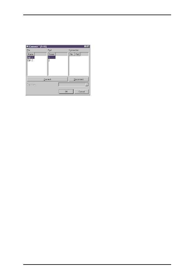
With the CONNECT command you specify which pins are taken to which
package pads.
Click the Connect button now.
The Connect window
In this example the resistor gate has been named G$1 automatically. This is
the reason why you see the pin name G$1.1 and G$1.2 in the column Pins .
The column Pad shows the pads placed in the package. Click on a pin and a
pad entry and click the Connect button. If you want to disconnect a pin
from a pad, select the pair in the Connection column and click Disconnect.
OK ends the CONNECT command and closes the window.
You can enter information concerning the device after clicking the
DESCRIPTION command. The entered text will be displayed in the Con-
trol Panel, when you select the device in the tree view. It will also be
checked by the search function of the ADD command.
Now the definition of the resistor is complete. You can use it in a sche-
matic now.
54
EAGLE-Tutorial
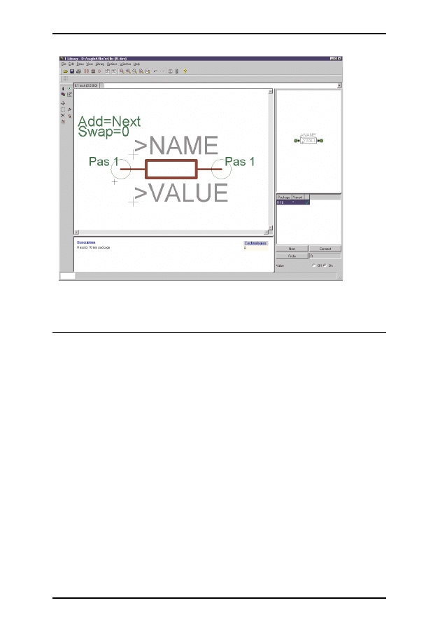
The Device Editor
21 Output of Drawings and Manufacturing Data
EAGLE can output drawings, for example for documentation purposes,
using the PRINT command. This command can be found in the File menus
of the Schematic or Layout Editor.
You can use the printers defined under Windows with this command. The
Linux version generates Postscript files that can be sent to lpr or to a file.
A printout of the drawing in the active editor window with the actual layer
settings (DISPLAY command) will be generated.
Film and manufacturing data are generated with the CAM Processor. Start
it with the icon in the action toolbar of the Layout Editor window.
The CAM Processor uses its own drivers, which can be defined or modified
by the user (see file eagle.def in directory eagle/bin).
Data for a bill of material, for mounting, milling or testing machines etc.
can be generated with the help of EAGLE User Language Programs. Infor-
mation about ULP's can be found in the file headers or with the help of the
descriptions in the Control Panel.
55
EAGLE-Tutorial

Output a Schematic with the PRINT Command
The schematic demo1.sch is to be printed in black/white and full format on
one page.
Load the file demo1.sch and click the PRINT icon in the action toolbar.
Check the boxes Black, Solid and Rotate (as the drawing is in landscape for-
mat). The boxes Mirror and Upside down are not marked.
For both Scale factor and Page limit type in 1. This specifies that the draw-
ing is to be output at a scale factor of 1, provided it fits onto one page. If
not, EAGLE changes the scale factor, so that the drawing does fit onto one
page. With Page limit 0 the drawing will always be printed with the set scale
factor.
The printer can be selected by using the button Printer.
The button Page leads you to the page setup parameters. If the box Caption
is checked, the drawing will be printed with a footer, containing the file
name, date, time, and scale factor.
Generating Gerber Data with the CAM Processor
The same steps are usually required for each board whenever films and
manufacturing data are generated. This process can be defined as a CAM
Processor job.
The file gerber.cam, which can be found in the default subdirectory for
CAM jobs, automates the output of Gerber data for double sided boards.
Attention: The process described can only be used for Gerber photoplotters
with flexible aperture wheels, not for photoplotters with fixed aperture wheels.
Please contact your board house to confirm which data are needed.
Load the job into the CAM Processor, either by double-clicking the entry
with the name gerber.cam in the Control Panel's tree view (CAM Jobs), or
by clicking the CAM Processor icon in the Layout Editor window and se-
lecting gerber.cam in the file dialog (
⇒
File/Open/Job).
In case you have started the CAM processor from the Control Panel, load
the board file demo3.brd:
⇒
File/Open/Board and
• •
demo3.brd
Click the button Process Job and confirm both prompts Delete name.$$$...
and More than ... with
•
OK.
Now all of the necessary files will be written into the Project directory
(where the drawing and board files for this project are located).
The files have the following meanings:
56
EAGLE-Tutorial

demo3.cmp
Component side
demo3.sol
Solder side
demo3.plc
Silkscreen for component side
demo3.stc
Soldering mask for the component side
demo3.sts
Soldering mask for the solder side
demo3.whl
Aperture wheel file
demo3.gpi
Information file, not relevant
demo3.$$$
Temporary file, to be deleted
The first six files need to be sent to your board manufacturer.
Drilling data can be generated accordingly by using the job excellon.cam.
Before you start the CAM processor you have to generate a Rack file which
contains a tool list for the drilling machine. To generate it, start the User
Language program drillcfg.ulp with the RUN command in the Layout Edi-
tor window. The ULP generates a file boardname.drl that will be read by
the CAM Processor.
Further information can be found on the CAM Processor help pages.
22 Data Exchange with EAGLE User Language
EAGLE comes with an integrated C-like User Language interpreter which
has access to virtually all data (in EAGLE or external files). User Language
programs can create any file type and therefore generate any data format
used by other software or hardware. A good example is the file bom.ulp
which generates a bill of material.
Please have a look at the files with the extension *.ulp and the User Lan-
guage section of the help function to get a better idea of the possibilities in-
herent in the program.
Additional User Language programs can be found on our web pages:
http: www cadsoftusa com download htm (UserFiles directory).
23 Script Files - Flexible Input Interface
Script files are text files which can contain any EAGLE command (see
SCRIPT command). Script files enable the user to implement his own
functions. Thus you have a flexible input interface defined by the EAGLE
command syntax (see EAGLE help).
57
EAGLE-Tutorial
Document Outline
- Table of Contents
- 1 What to expect from this Manual 7
- 2 System Requirements 7
- 3 Features of EAGLE 8
- 4 Installation and Program Start 10
- 5 Individual EAGLE Setup 10
- 6 The Concept of the EAGLE User Interface 11
- 7 Typographic Conventions 11
- 8 Control Panel 15
- 9 Load File and Select Monitor Zoom 17
- 10 Selecting Layers for Display 18
- 11 Setting up Grid and Unit 18
- 12 Wires, Circles, Arcs, Rectangles, and Text 19
- 13 Using Libraries 23
- 14 Drawing a Schematic 26
- 15 Function Keys 36
- 16 Automatic Forward&Back Annotation 36
- 17 Designing a PC Board 37
- 18 Autorouter 48
- 19 Design Rule Check 49
- 20 Libraries 50
- 21 Output of Drawings and Manufacturing Data 55
- 22 Data Exchange with EAGLE User Language 57
- 23 Script Files - Flexible Input Interface 57
Wyszukiwarka
Podobne podstrony:
eagle tutorial
Anime drawing tutorials [ENG]
Eagle tutorial
ANSYS Tutorial eng
eagle tutorial
Anime drawing tutorials [ENG]
Blender ENG Tutorial 01 Cartoonish Landscape
tutorial eagle fr
chrystus jest zyciem mym ENG
Przegląd rozwiązań konstrukcyjnych wtryskarek (ENG)
Assembler ENG
Frequenzimetro eng 2003
bugzilla tutorial[1]
więcej podobnych podstron