
Mastercam to Mazatrol Post-Processor Tutorial 8/18/2005
Mastercam
®
to
Mazatrol
®
Post-Processor Tutorial
Introduction
The following tutorial instructs the user in the approach to programming that allows a
Mastercam
®
file with it’s associated toolpaths to output the desired Mazatrol
®
code.
It is not the intention of this tutorial to teach the use of Mastercam
®
or the Mazatrol
®
conversational system. It is assumed that the user of this product has been instructed in
the use of the former items. We provide in addition to this tutorial both a help file
accessible when in the Mazatrol Menu by clicking on Help and a Mazak for Mastercam
Manual - For Mastercam instruction please contact your local Mastercam reseller. For
mazatrol instruction please refer to your Mazak/ Mazatrol Programming Manuals or
contact your local Mazak representative.
S
S
e
e
c
c
t
t
i
i
o
o
n
n
1
1
.
.
P
P
r
r
o
o
g
g
r
r
a
a
m
m
m
m
i
i
n
n
g
g
a
a
M
M
i
i
l
l
l
l
P
P
a
a
r
r
t
t
S
S
e
e
c
c
t
t
i
i
o
o
n
n
2
2
.
.
P
P
r
r
o
o
g
g
r
r
a
a
m
m
m
m
i
i
n
n
g
g
a
a
L
L
a
a
t
t
h
h
e
e
P
P
a
a
r
r
t
t
Note: This text was compiled using Version 8.0.8 of the Mazatrol Product – some dialogs
presented may have changed or you may be using either an earlier or later version of the
software.
1
Mastercam to Mazatrol Post-Processor Tutorial 8/18/2005
S
S
e
e
c
c
t
t
i
i
o
o
n
n
1
1
-
-
M
M
i
i
l
l
l
l
1
1
.
.
Creating simple face and contour toolpaths
Exercise 1 - Opening the part file
1. Choose Main Menu, File, Get
2. Navigate to the folder with the tutorial parts.
3. Select Mazak_1_Mill.mc9; then choose Open.
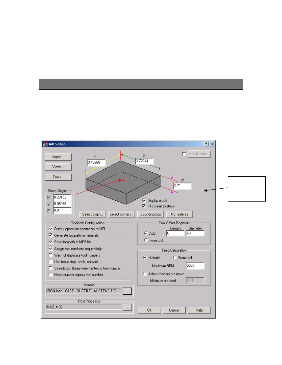
4. Choose, Main Menu, Toolpaths, Job Setup
5. Enter settings as shown.
This setting
will be set as
INITIAL Z
2
Mastercam to Mazatrol Post-Processor Tutorial 8/18/2005
Note: Job Setup settings will affect the first line of the mazatrol PNR and MAT i.e. the
material selected will be output and the Z depth of the material will be output as
INITIAL-Z see below:
PNR MAT INITIAL-Z ATC MODE MULTI MODE MULTI FLG PITCH-X PITCH-Y
0 IRON 0.7100 1 OFF
The other settings will have to be manually entered by the user if desired either using the
editor (if available) or at the control. Also the values for federate and spindle speed that
are set in the mastercam parameter pages will also output to the Mazatrol code.
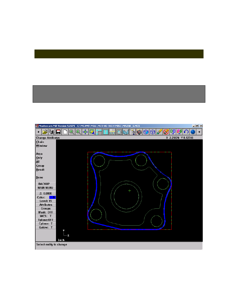
Exercise 2 - Creating Facing Toolpath for outside
profile
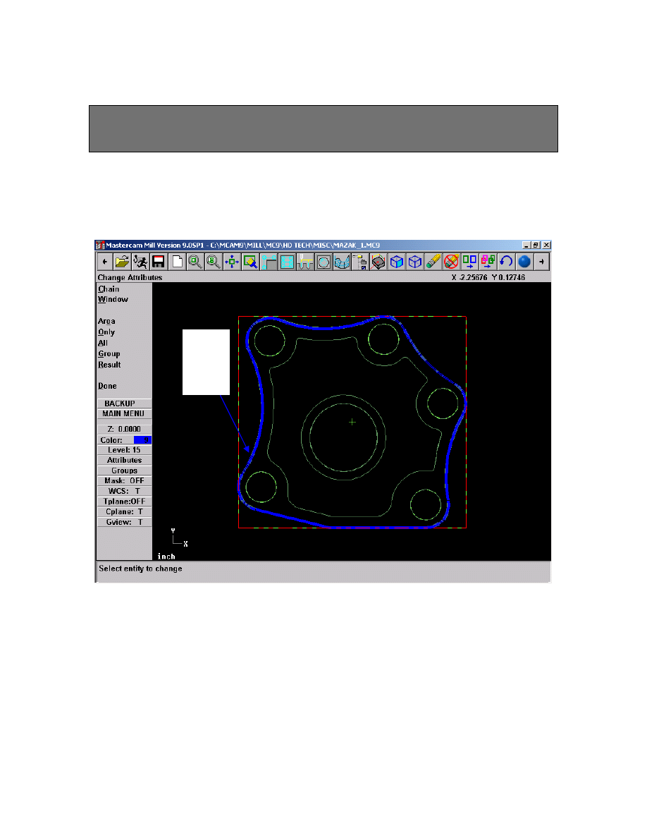
1. Choose Main Menu, Toolpaths, Face
2. Select outside profile as shown using chain
2. Select Done
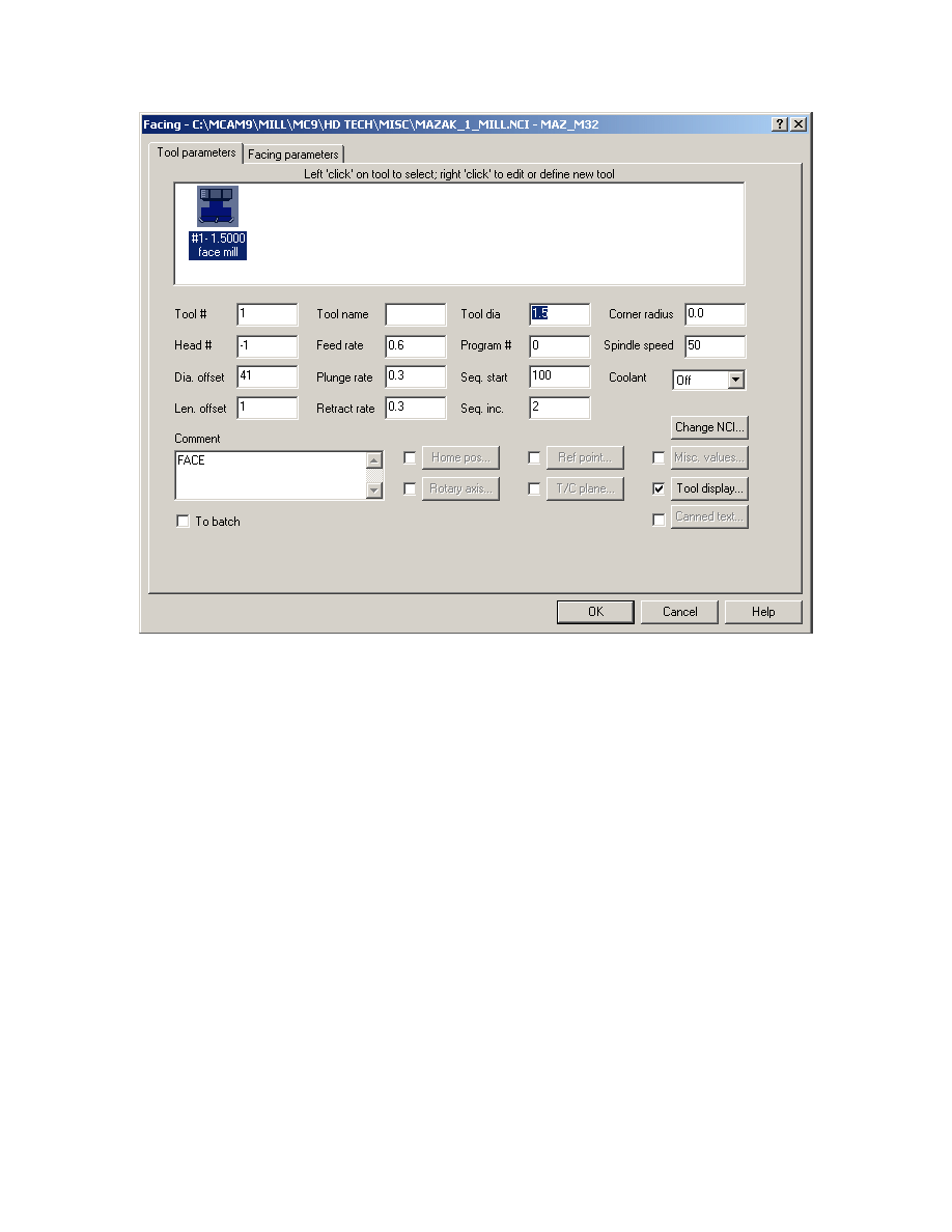
3. Select or Create a 1.5”Dia Face Mill as shown.
3
Mastercam to Mazatrol Post-Processor Tutorial 8/18/2005
4. Click on Misc. Values button and set Face Machining to Face as shown below
4
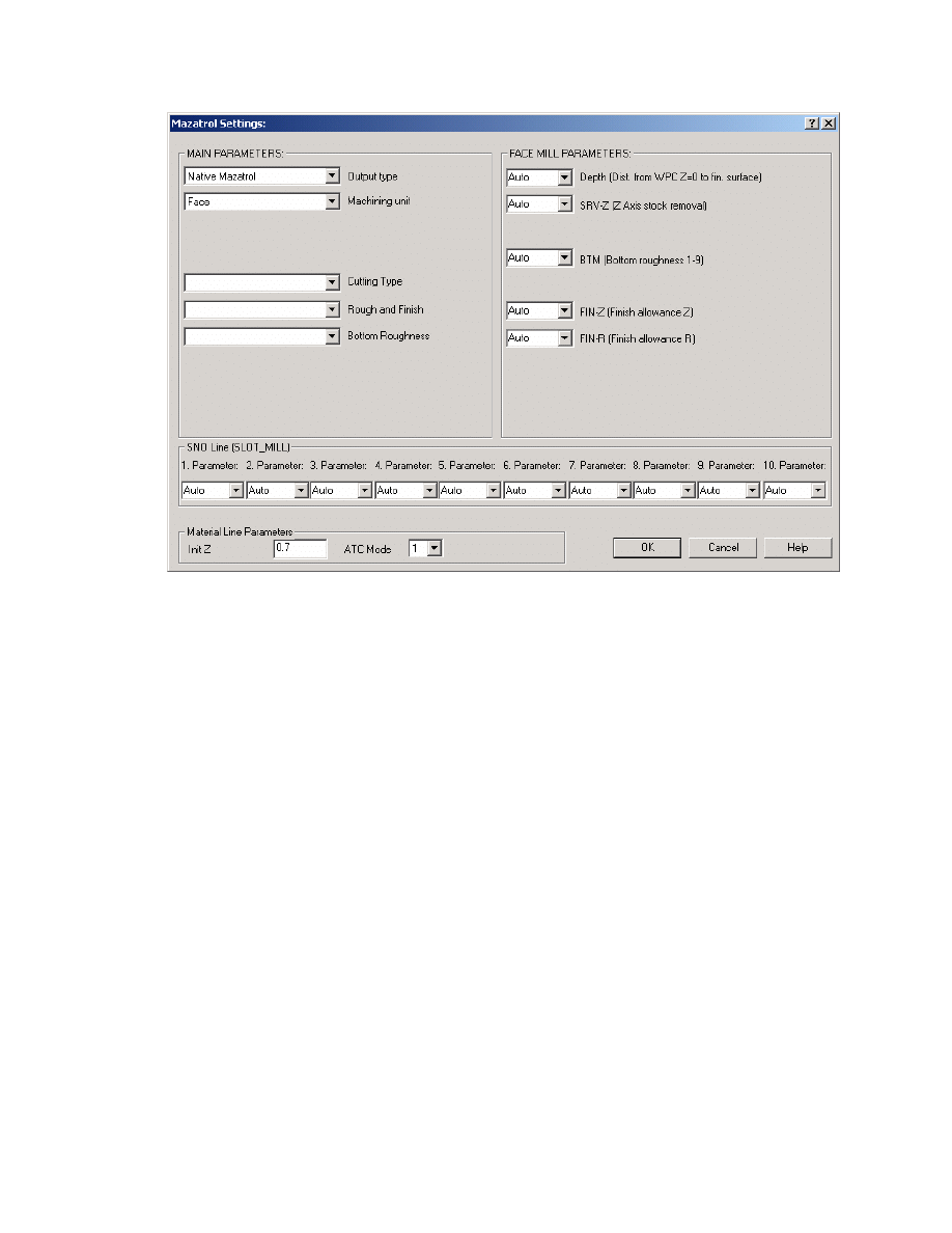
Mastercam to Mazatrol Post-Processor Tutorial 8/18/2005
5. Click OK when done.
6. Click on Facing Parameters Tab and set Values as shown;
5
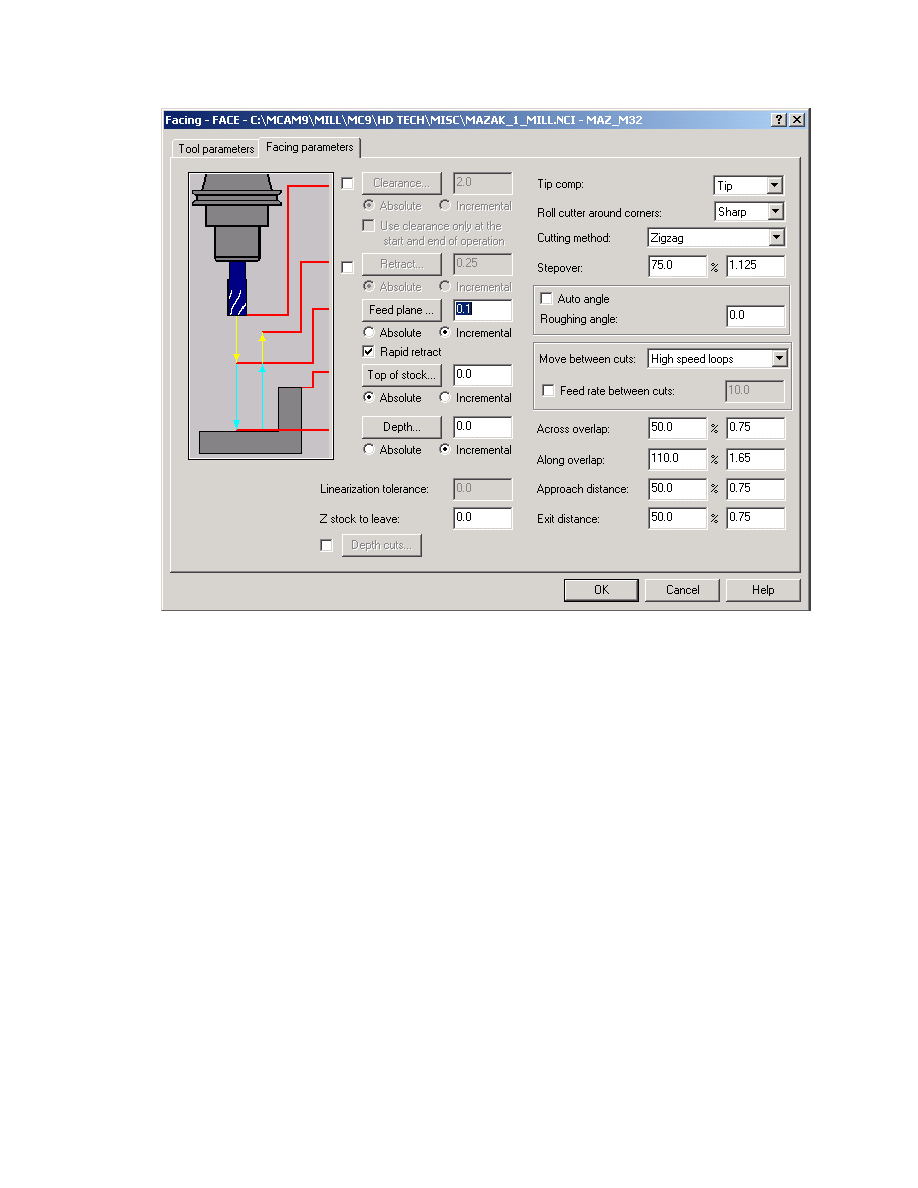
Mastercam to Mazatrol Post-Processor Tutorial 8/18/2005
7. Click on OK when completed.
6
Mastercam to Mazatrol Post-Processor Tutorial 8/18/2005
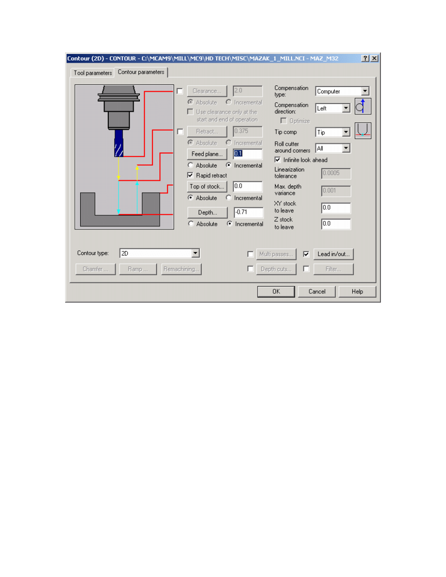
Exercise 3 - Creating Contour Toolpath for outside
profile
1.
Choose Main Menu, Toolpaths, Contour
2.
Select outside profile as shown using chain
Select
Chain
Here
3.
Select Done
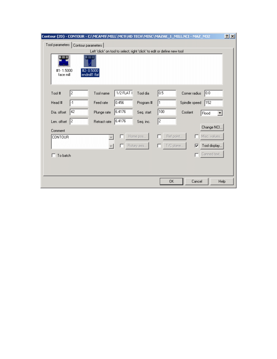
4.
Select 0.5” Dia Flat end Mill as shown.
7
Mastercam to Mazatrol Post-Processor Tutorial 8/18/2005
5. Click on Misc. Values button and modify settings as shown below
8
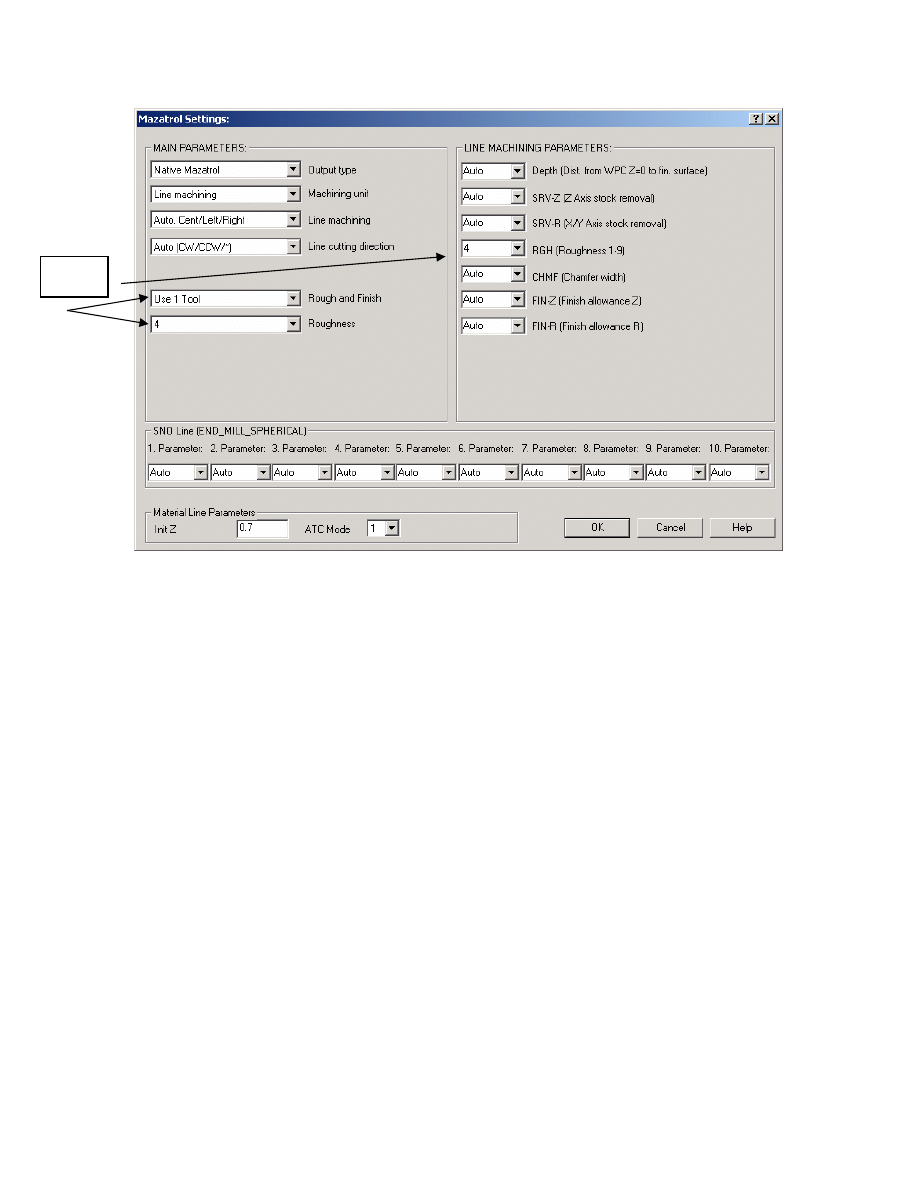
Mastercam to Mazatrol Post-Processor Tutorial 8/18/2005
Change
values
Note: As you may notice – the Misc. Values dialog box allows every setting in the
mazatrol SNO line and UNIT (UNO) line to be set by the user and override the
automatically set values output by the post-processor. This will be shown in more detail
in the next chapter.
9
Mastercam to Mazatrol Post-Processor Tutorial 8/18/2005
Note: Another advantage of using the Mazatrol Post-Processor is that we can output
lead-in and lead-out values from mastercam. In the previous settings we have computer
compensation with left direction. Therefore only use LINE-CTR so that correct accuracy
is maintained. You can of course also use other type of compensation such as LINE-LFT
and LINE-RGT but in those cases it would be safer to set Compensation to Control so
that the Control picks up the tool radius and compensates accordingly.
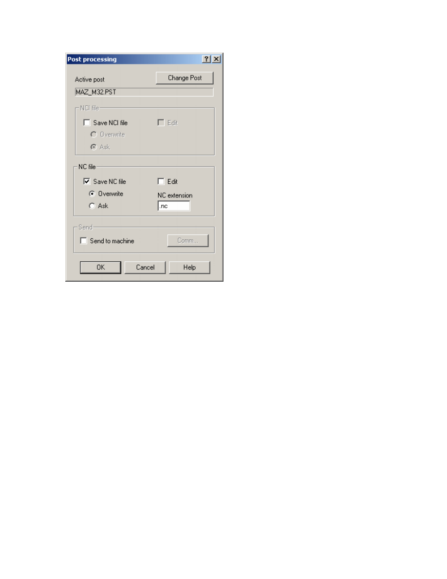
6. Select Done. This should return you to the operations manager. Select Post
Modify settings as shown below. (In this example we are using the M32 post-processor
shown as MAZ_32.PST. Yours may vary but all the Mazatrol Post-Processors will have
the format of MAZ_XXX.PST)
10
Mastercam to Mazatrol Post-Processor Tutorial 8/18/2005
7. Select OK. The file name dialog should then appear as shown below:
Note: We do not need to create an NC file but Mastercam needs to have this setting so
that the post-processor can function
8. Click Save.
11
Mastercam to Mazatrol Post-Processor Tutorial 8/18/2005
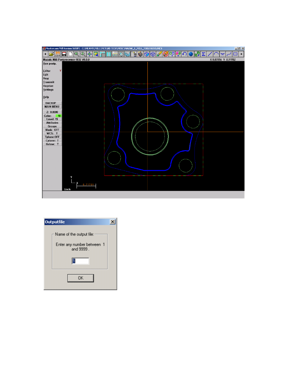
The Mazak Menu will then appear in place of the Mastercam Main Menu
10. From this menu select Run postp. to run the Mazatrol Post.
11. Select a number between 1 and 9999 and hit OK. This will be the program number
for your Mazatrol output file.
12
Mastercam to Mazatrol Post-Processor Tutorial 8/18/2005
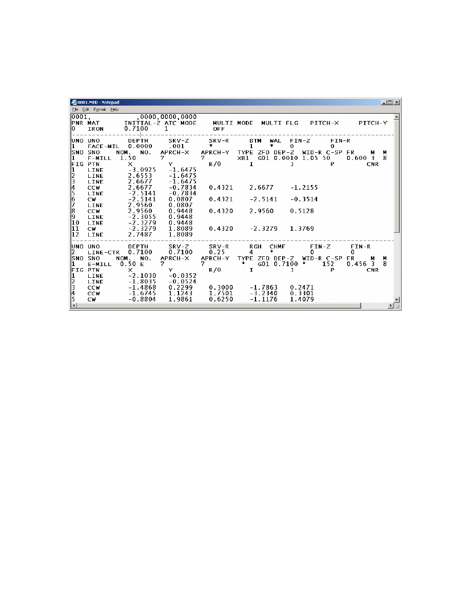
You should then see output as shown below (output below is shown as a Notepad
window – if you have purchased the Editor and you have the Editor set to Yes in the
Mazatrol Menu the output will open up in the Mazatrol Editor)
12. Close this window.
We will then send this program to the controller
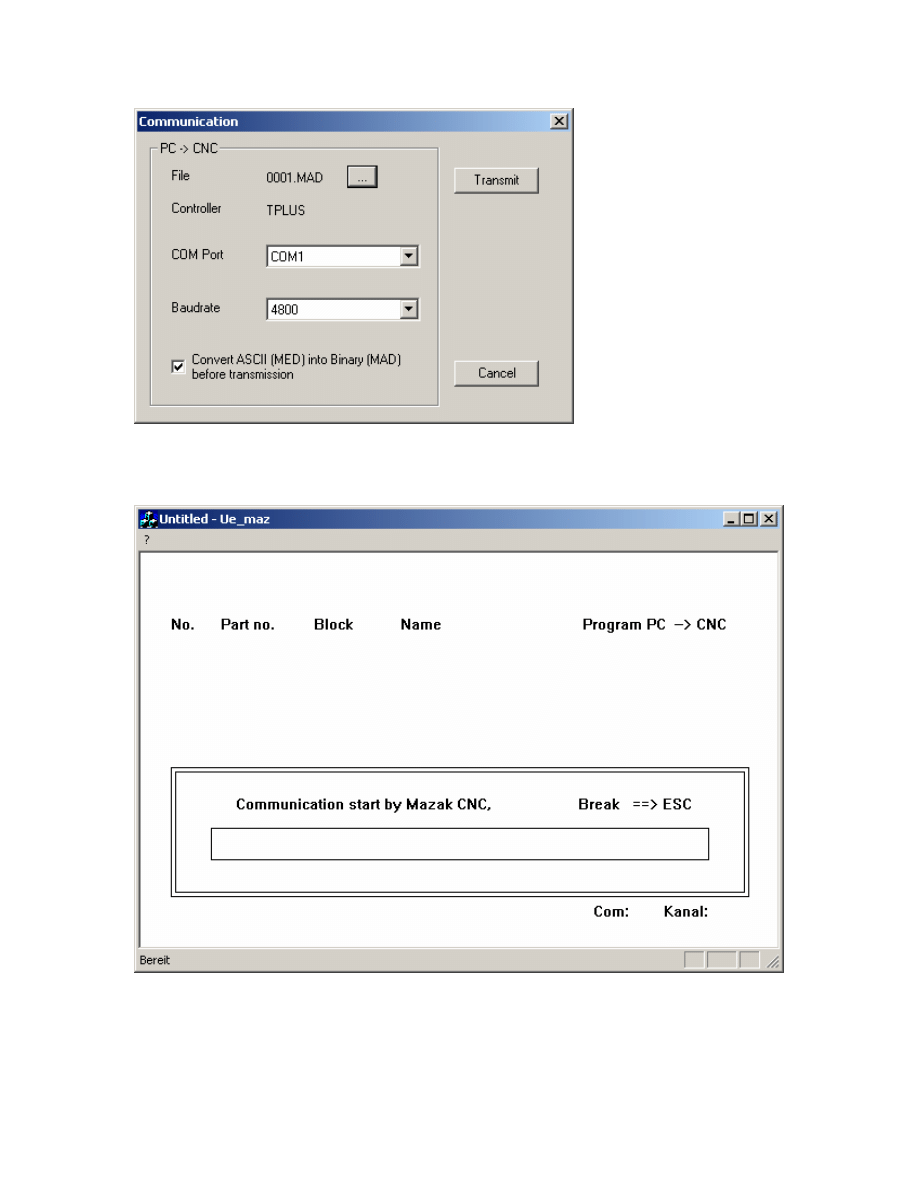
13. From the Mazatrol Menu select Transmit.
13
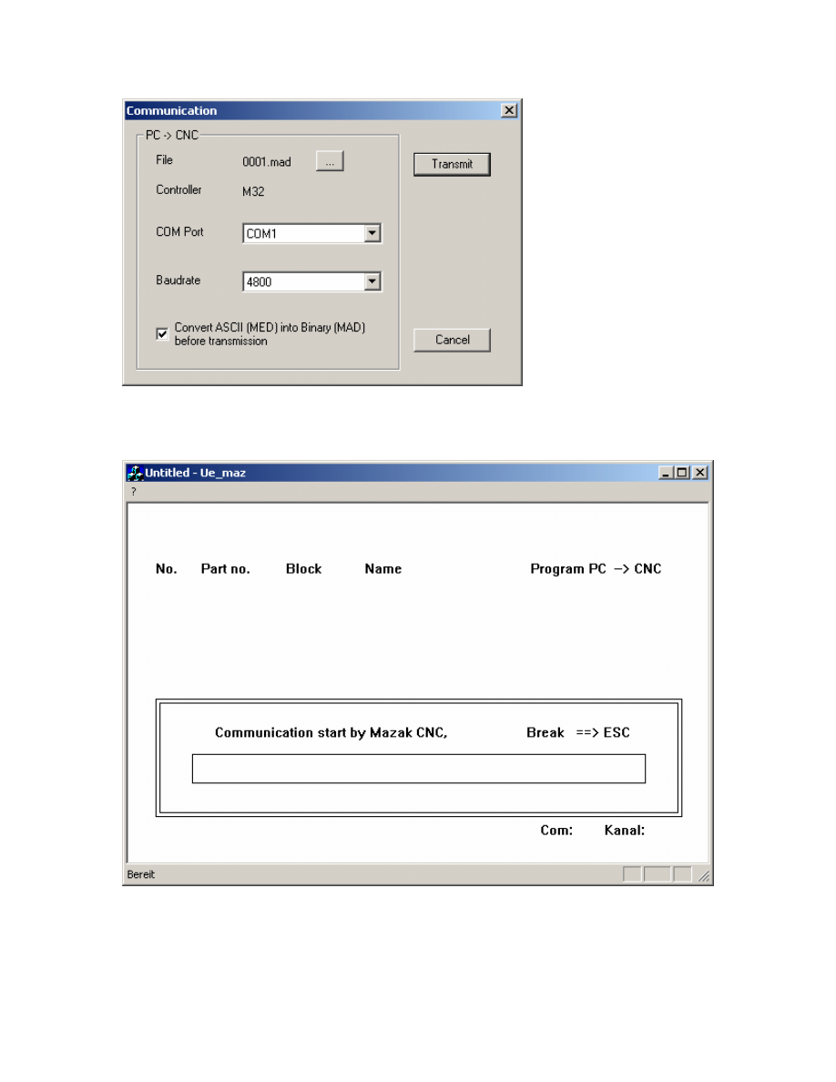
Mastercam to Mazatrol Post-Processor Tutorial 8/18/2005
15. If the settings are correct and you are using the Built in DNC click Transmit.
This is the progress bar.
14

Mastercam to Mazatrol Post-Processor Tutorial 8/18/2005
To complete the download complete the following steps at
The Mazak Controller.
¾ PROGRAM-LIST or INDEX
¾ DATA IN/OUT
¾ CMT-NC
¾ INPUT
¾ ENTER THE PROGRAM NUMBER AND SELECT INPUT
¾ HIT START
You should then see the file being downloaded by a blue bar filling the progress bar
shown above.
Congratulations! You have created your first mastercam to mazatrol program.
16. Hit esc once the Progress Bar is completed.
17. Hit esc to get back to Mastercam Main Menu.
Save File as Mazak_1_Mill_1.mc9
15
Mastercam to Mazatrol Post-Processor Tutorial 8/18/2005
2
2
.
.
Adding Pocketing and Drill Toolpaths
Exercise 1 - Creating Pocket Toolpath
We will re-open the file we had previously created to add some more toolpaths
1. Choose Main Menu, File, Get
2. Navigate to the folder with the tutorial parts.
3. Select Mazak_1_Mill_1.mc9; then choose Open.
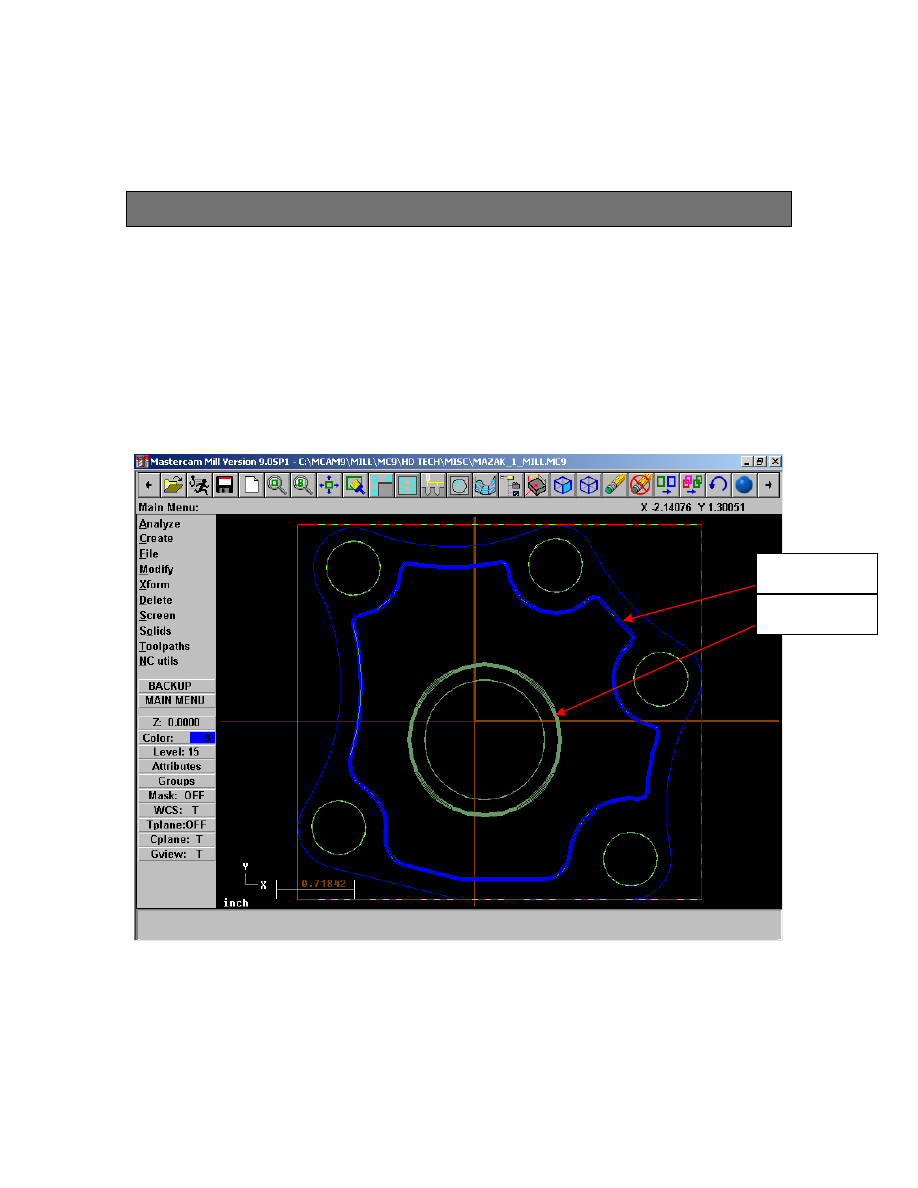
4. Choose Main Menu, Toolpaths, Pocket
5. Chain outside profile shown in Blue and Inside Island as shown in Green
Inside Island
Outside Profile
6. Select Done
16
Mastercam to Mazatrol Post-Processor Tutorial 8/18/2005
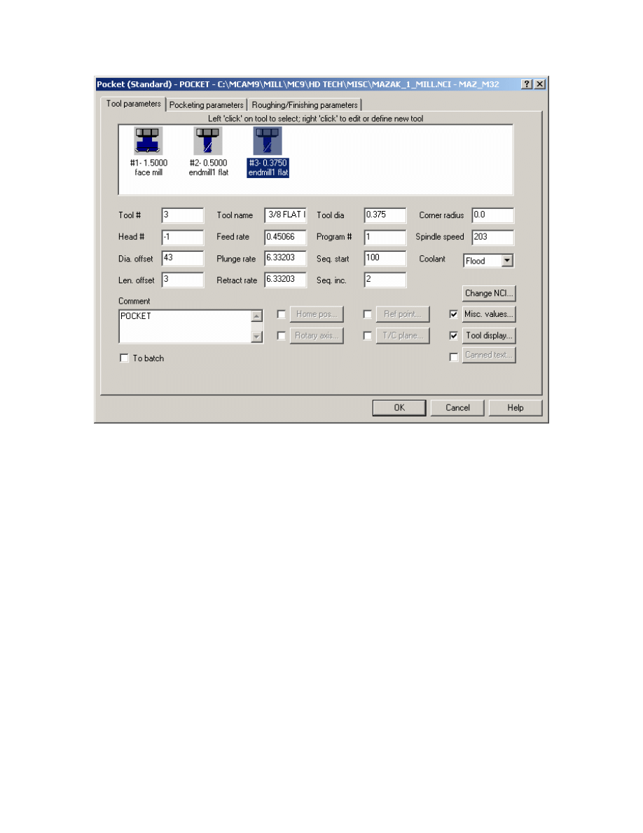
7. Set Tool Parameters as shown
17
Mastercam to Mazatrol Post-Processor Tutorial 8/18/2005
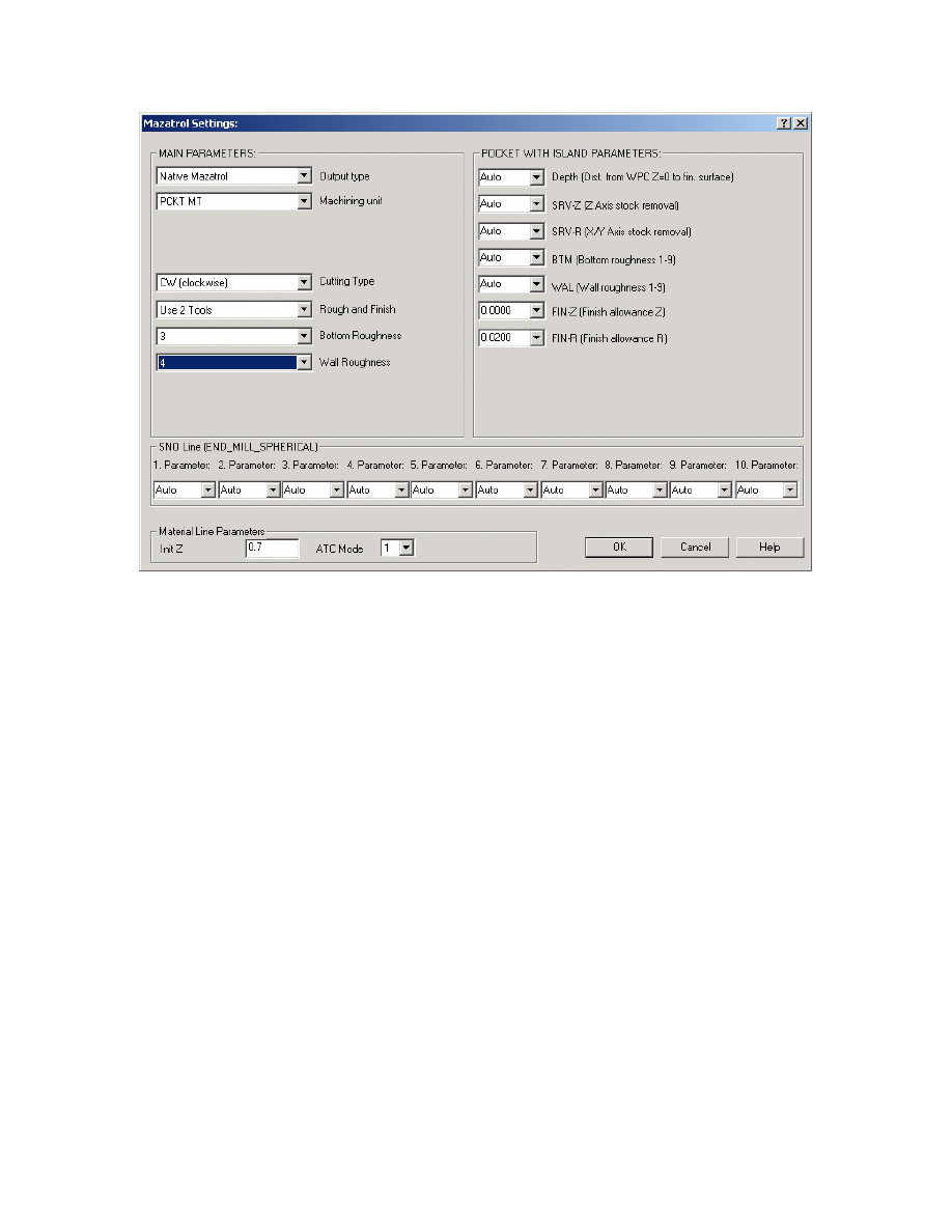
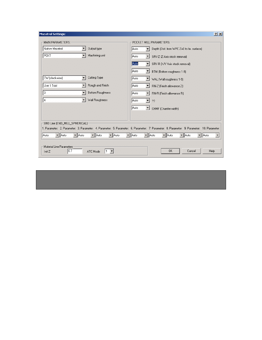
8. Set Misc. Values as shown:
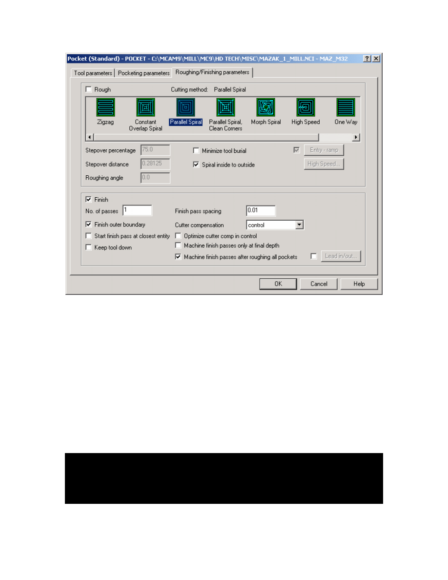
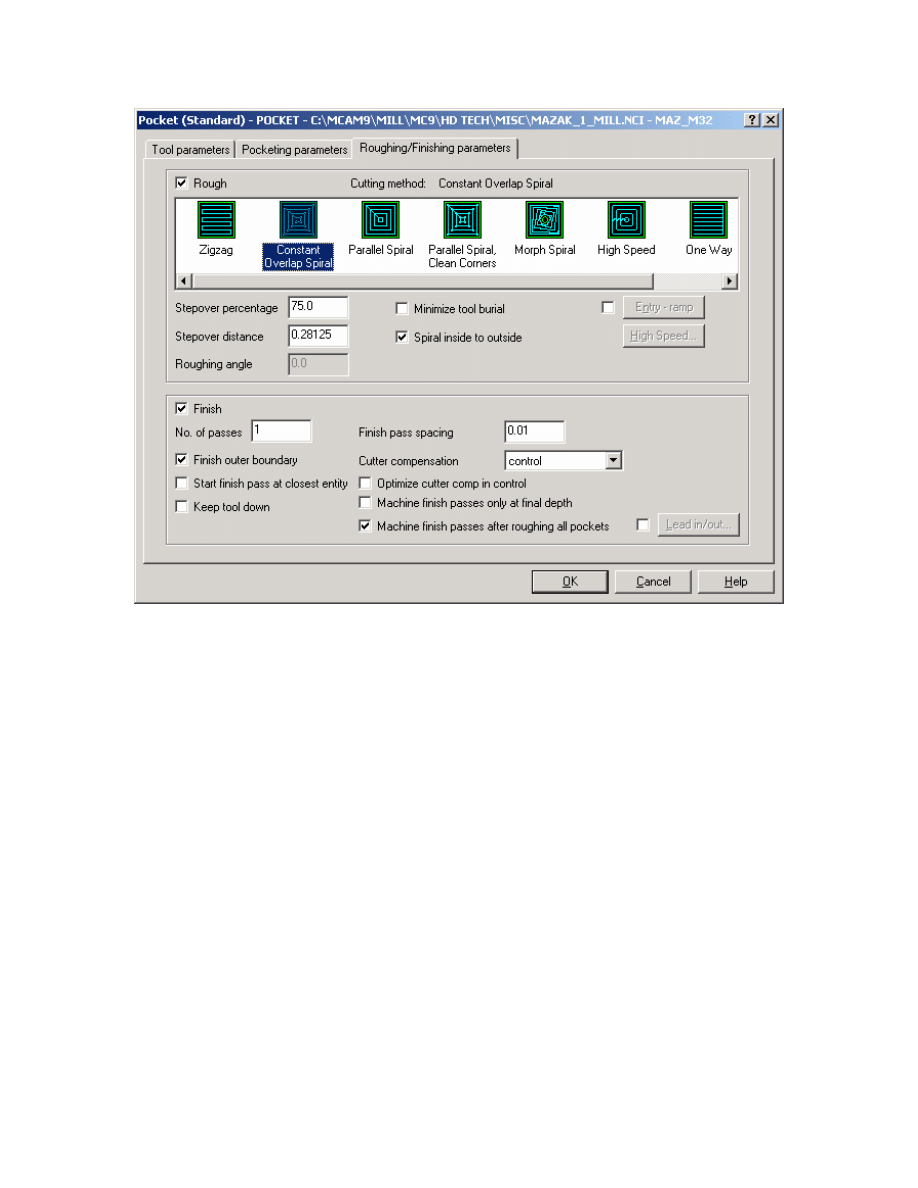
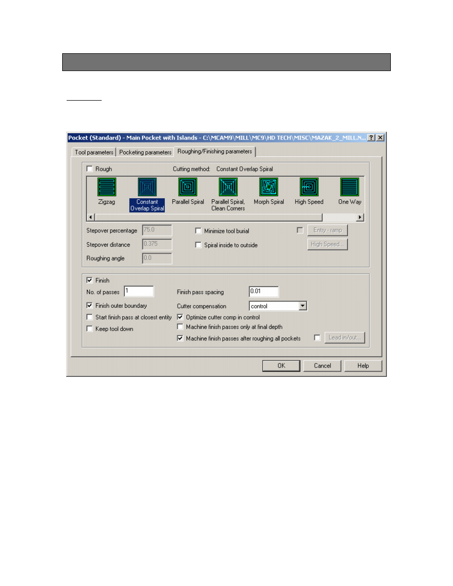
9. Set Pocketing Parameters and Roughing/Finishing Parameters as shown below:
18
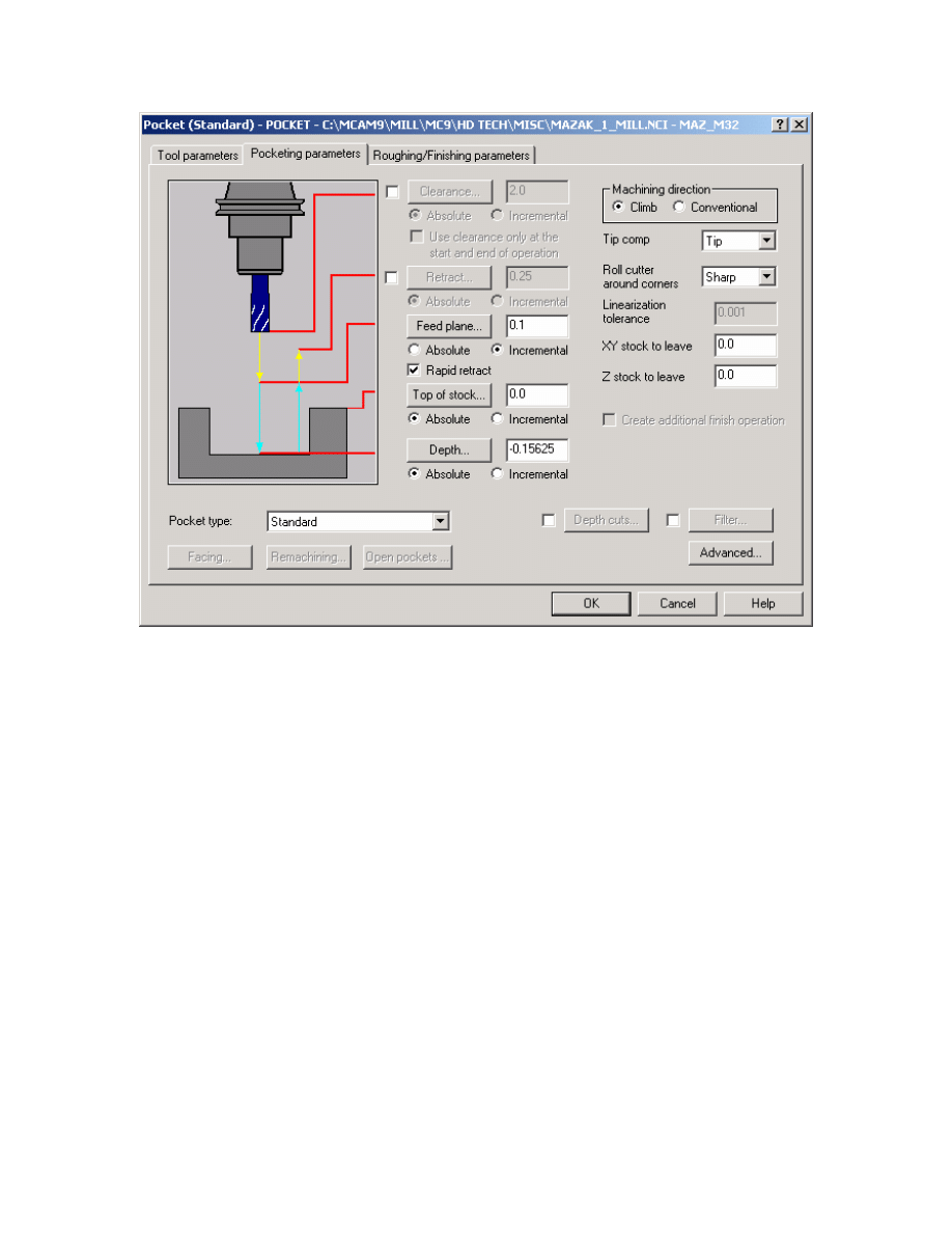
Mastercam to Mazatrol Post-Processor Tutorial 8/18/2005
19
Mastercam to Mazatrol Post-Processor Tutorial 8/18/2005
Note: It is best not to use Depth Cuts when machining pockets. If depth cuts are used
unnecessarily long code is output. It is best if you set the value SRV-Z within the misc.
values dialog.
Note: To have the option of either using one tool or two tools for roughing and finishing
we can set this at the Rough and Finish pull down menu in the Misc. Values dialog box
(this option is also available for contour machining equivalent to LINE machining in
Mazatrol). We have also set specific Bottom finishes and Wall finishes. In the mastercam
toolpaths it is not possible to create or activate many of these types of conversational
language settings therefore in many cases the only access to these parameters will be
through the misc. values pages as shown above.
Sample output below when this is processed.
--------------------------------------------------------------------------------
UNO UNO DEPTH SRV-Z SRV-R BTM WAL FIN-Z FIN-R
1 PCKT.MT 0.0912 0.0912 * 1 1 0 0
SNO SNO NOM. NO. APRCH-X APRCH-Y TYPE ZFD DEP-Z WID-R C-SP FR M M
1 E-MILL 0.38 E
?
? CW
G01 0.0912
0.27 203 0.450 3 8
2 E-MILL 0.38 E
?
? CW
G01 0.27 203 0.450 3 8
20
Mastercam to Mazatrol Post-Processor Tutorial 8/18/2005
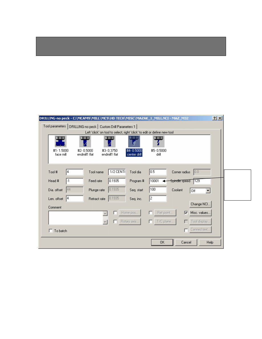
Exercise 2 - Creating Drill Toolpaths with Multiple
Tools
Select the following:
1. Main Menu
2. Toolpaths
3. Drill
4. The five (5) x 0.5”dia circles
5. Done
6. Done
Set
Program
# to
10001
Select 0.5”center drill as shown
In order for all the tools to be captured and appear at the top of the drill line set the
Program # to the value shown. (Values of 10001 –10099 may be used to group
common tools together for this type of operation)
21
Mastercam to Mazatrol Post-Processor Tutorial 8/18/2005
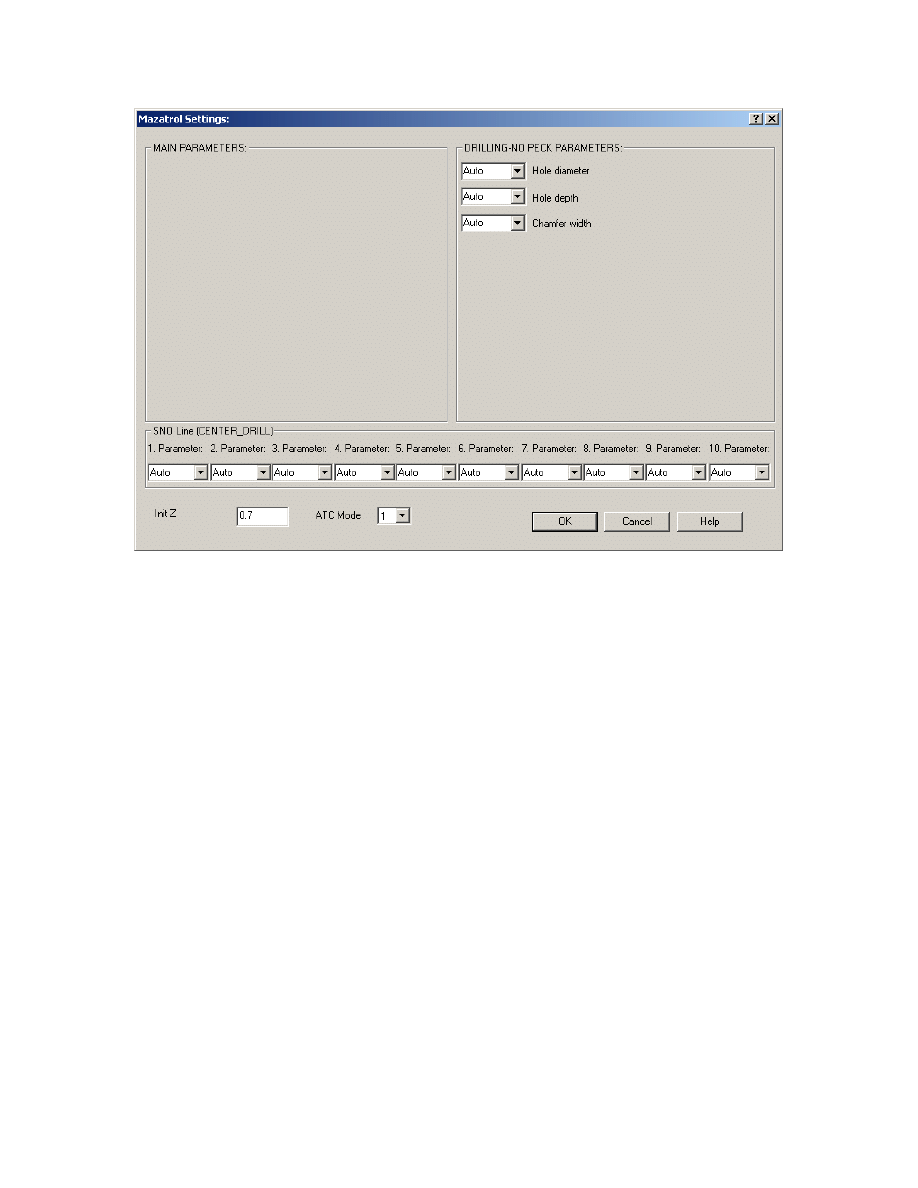
7. Misc. Values Leave settings on Auto as shown
22
Mastercam to Mazatrol Post-Processor Tutorial 8/18/2005
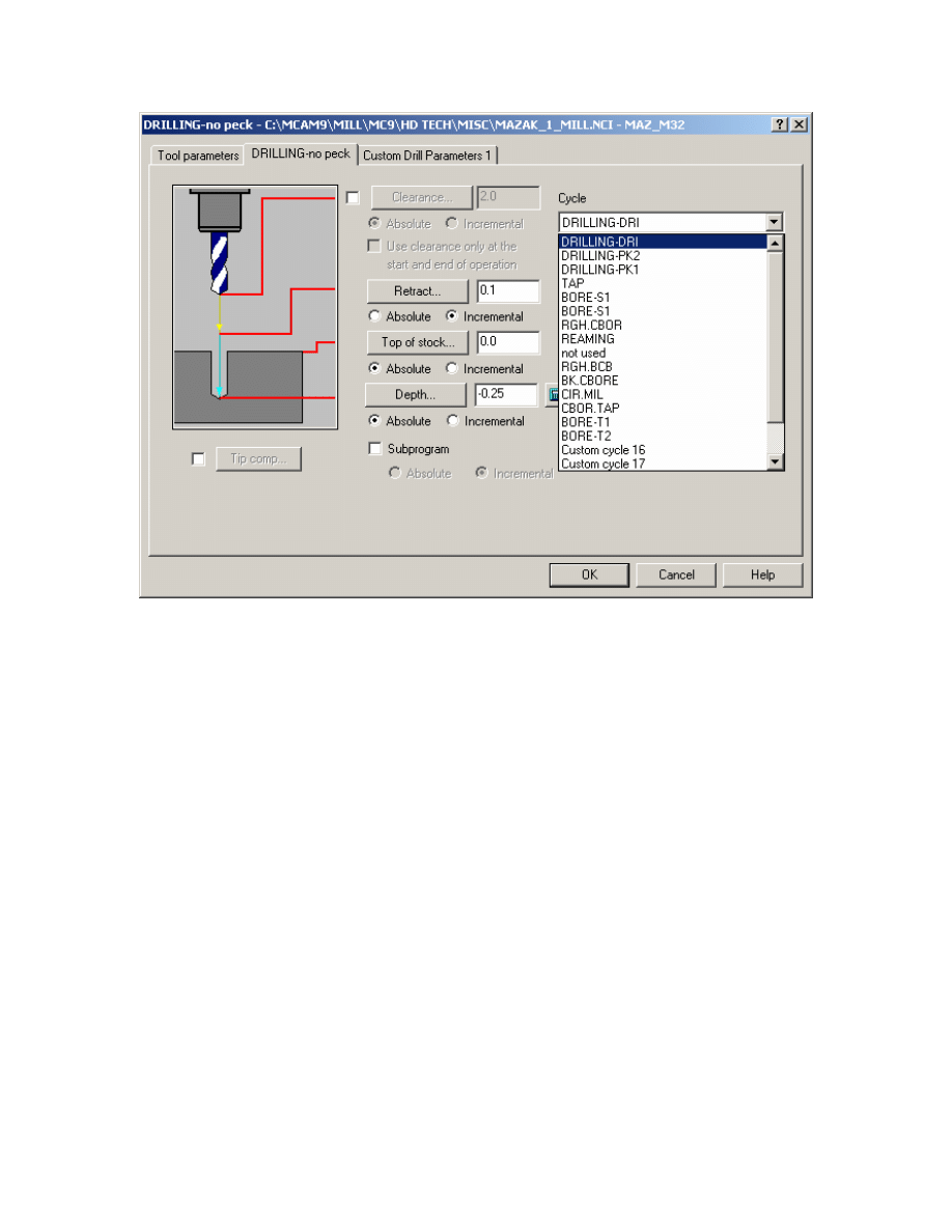
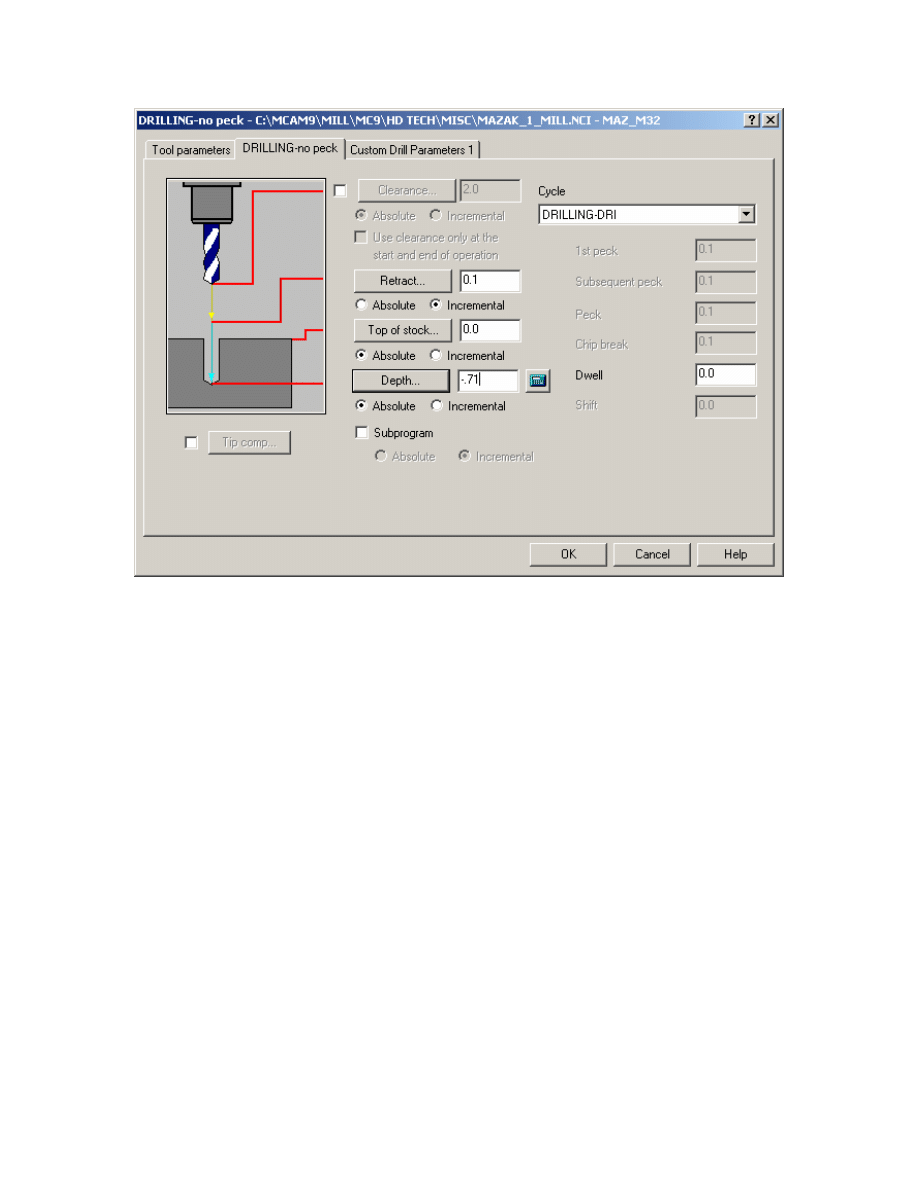
8. Go to Drilling and set DRILLING – DRI as shown
Note: All the Drill Cycles available to Mazatrol are accessible via Drill Cycle Menu as
shown above.
9.OK
23
Mastercam to Mazatrol Post-Processor Tutorial 8/18/2005
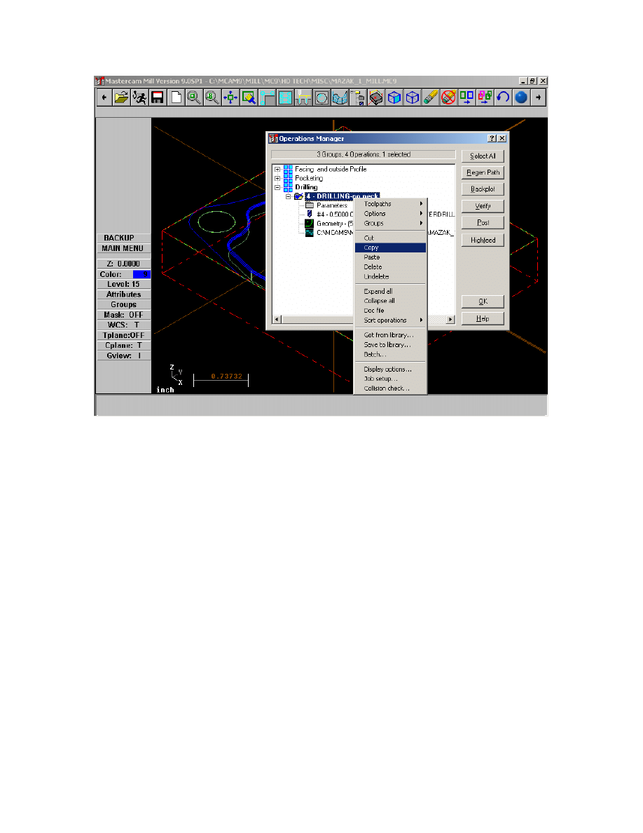
Now we will copy the previous operation. Therefore the only changes we need to make
will be the tool we want to use and the drilling depth. All the other values will stay the
same.
24
Mastercam to Mazatrol Post-Processor Tutorial 8/18/2005
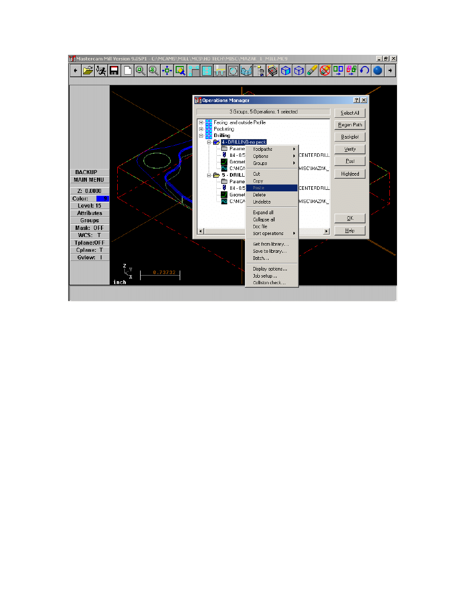
11. Paste new operation
25
Mastercam to Mazatrol Post-Processor Tutorial 8/18/2005
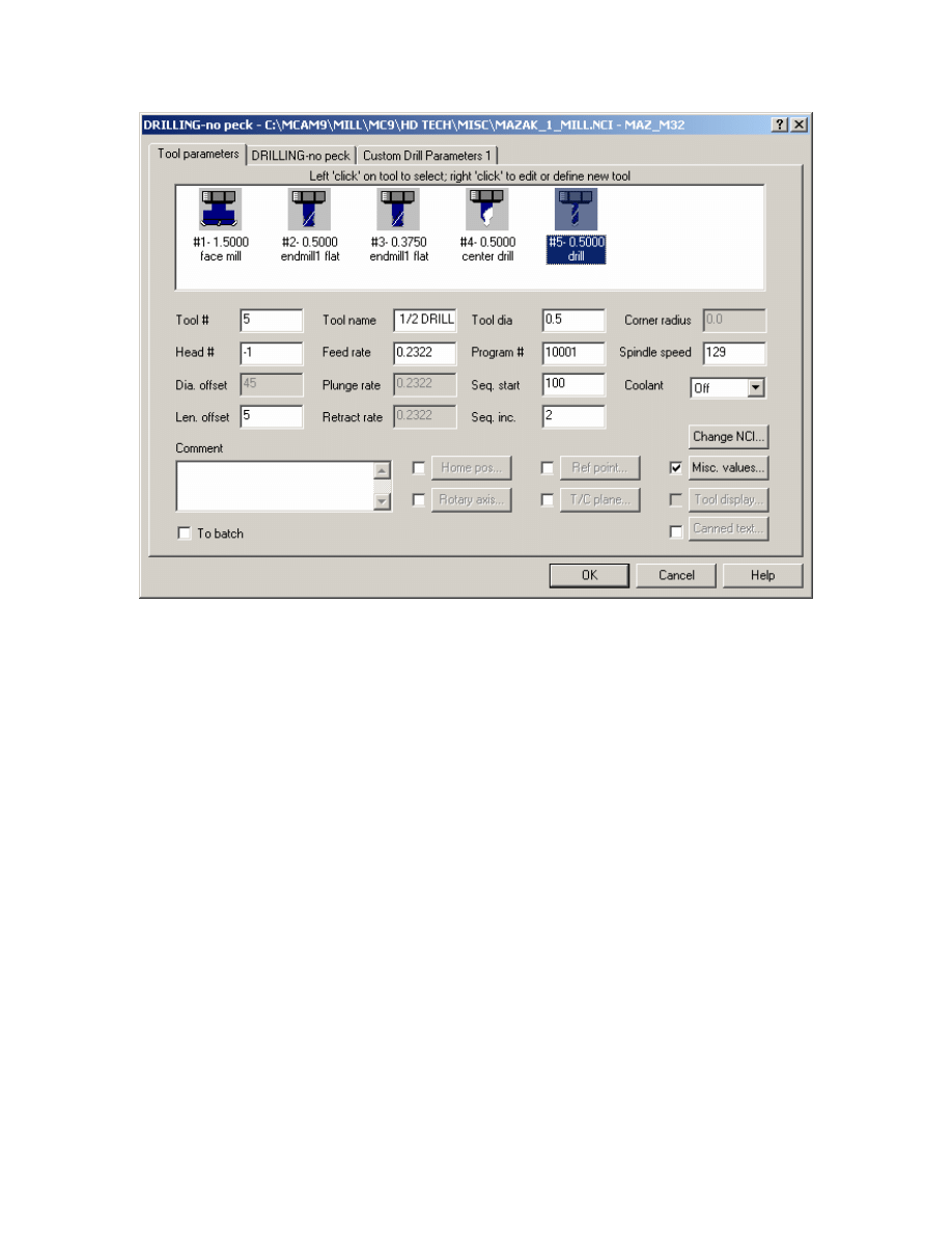
12. Select 0.5” tool as shown
26
Mastercam to Mazatrol Post-Processor Tutorial 8/18/2005
13. Set Depth as shown.
14. OK.
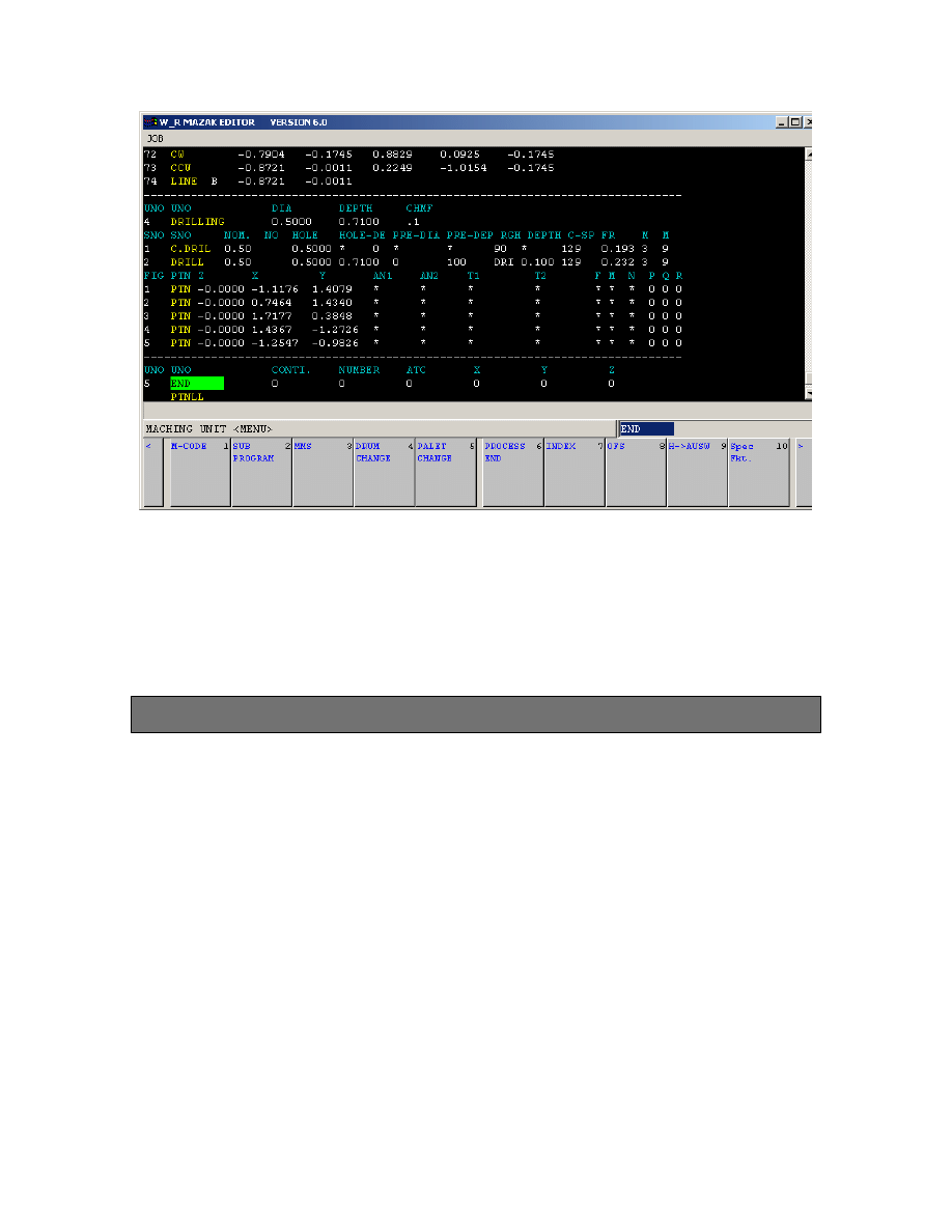
After posting the output will appear as shown below.
27
Mastercam to Mazatrol Post-Processor Tutorial 8/18/2005
15. Save File
16. Post File and view output.
3
3
.
.
Modifying a previously programmed part
Exercise 1 - Opening Part File
In this exercise the object is to modify an existing part previously programmed perhaps
for another type of control such as a Fanuc – or perhaps a situation where the
programmer wishes to get all the toolpaths built before adapting the output for Mazatrol.
1. Choose Main Menu, File, Get
2. Navigate to the folder with the tutorial parts.
3. Select Mazak_2_Mill.mc9; then choose Open.
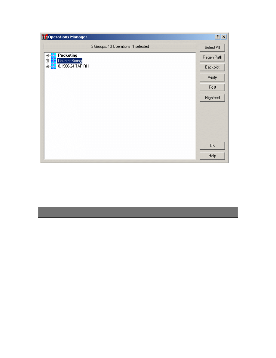
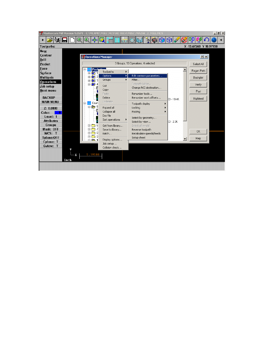
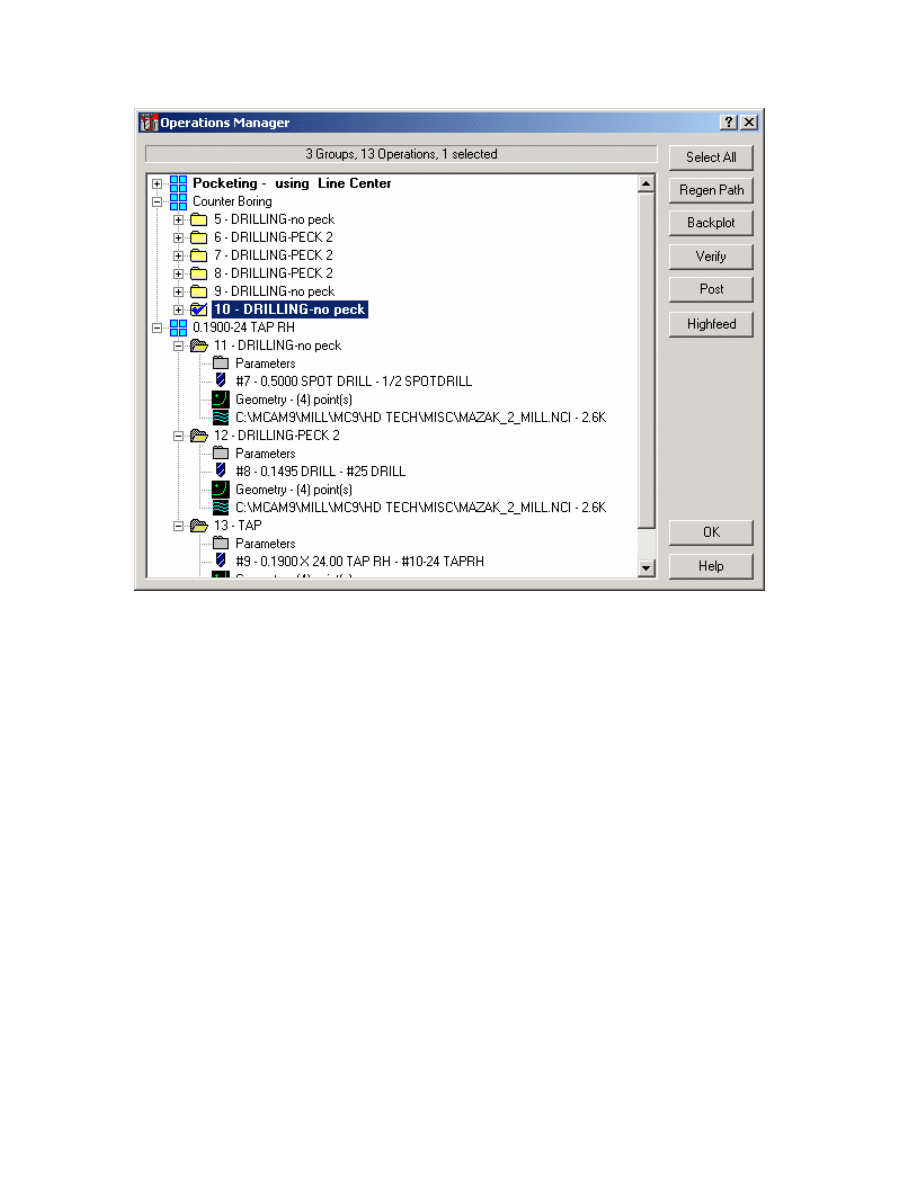
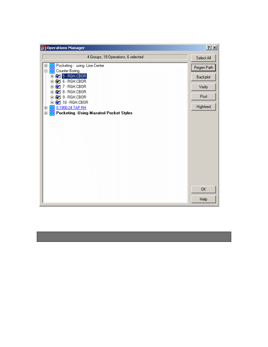
4. Go to Operations Manager you should see dialog as below
28
Mastercam to Mazatrol Post-Processor Tutorial 8/18/2005
In this file we have created a part in the using pocketing that would be very difficult to
program in Mazatrol because the pocket has multiple islands. We have also used a tool
that is too big to complete the machining of the pocket and then taken advantage of
Mastercam’s Pocket Remachining routine. As the part already has defined stock go ahead
and run verify out of the Operations Manager to see the current toolpaths.
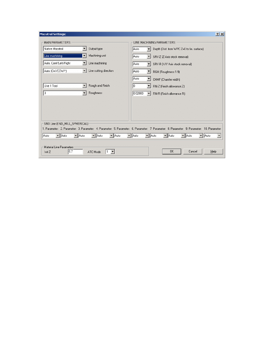
Exercise 2 - Line-Center output for Pockets
We have two options in this case. We could program all the pockets using line-center and
modifying settings as shown below – this would take advantage of mastercam’s many
different type of pocketing strategies available when setting the Roughing component or
we could program separate areas of the part using either Mazatrol’s Pocket or Pocket
MT. In this section we will program output as Line center.
29
Mastercam to Mazatrol Post-Processor Tutorial 8/18/2005
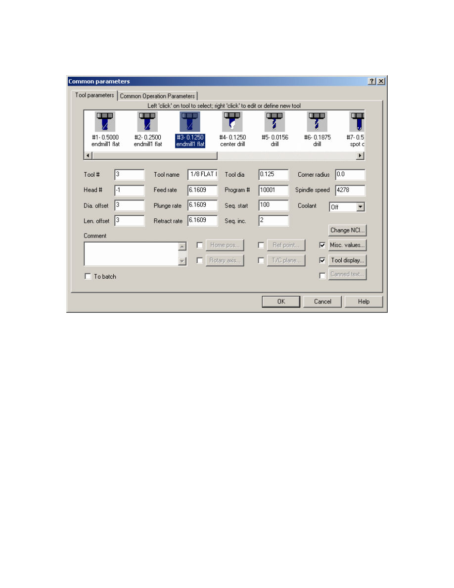
1. Fill in settings as shown below:
30
Mastercam to Mazatrol Post-Processor Tutorial 8/18/2005
2. Set all other pocket toolpaths programmed likewise using Edit Common Toolpath
parameters and go to Misc. Values button
31
Mastercam to Mazatrol Post-Processor Tutorial 8/18/2005
A section of the Mazatrol output will be as below:
PNR MAT INITIAL-Z ATC MODE MULTI MODE MULTI FLG PITCH-X PITCH-Y
0 ALUMINUM 1.0 0 OFF
--------------------------------------------------------------------------------
UNO UNO DEPTH SRV-Z SRV-R RGH CHMF FIN-Z FIN-R
1 LINE-CTR 0.3000 0.3000 0.25 3 * 0 0
SNO SNO NOM. NO. APRCH-X APRCH-Y TYPE ZFD DEP-Z WID-R C-SP FR M M
1 E-MILL 0.50 ? ? * G01 0.3000 * 1069 6.417 3 9
FIG PTN X Y R/0 I J P CNR
1 LINE 8.7198 9.2517
2 CCW 8.7600 9.4741 0.6350 8.1250 9.4741
3 LINE 8.7600 10.0514
32
Mastercam to Mazatrol Post-Processor Tutorial 8/18/2005
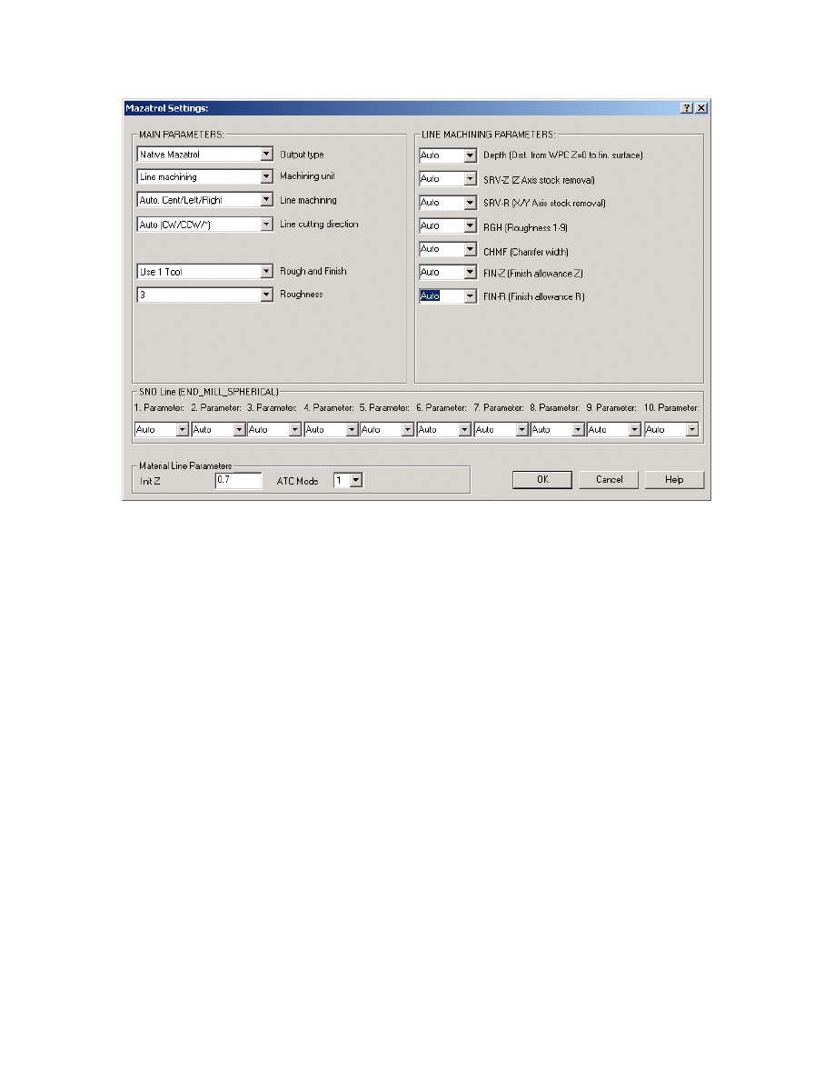
There will be times when you may wish to modify the settings that are automatically
calculated for those parameters on both the UNO (unit Line ) and SNO (Tool Cutting
Definition Line) this will be done as shown below. Again you will need to access the
Misc. Values Button.
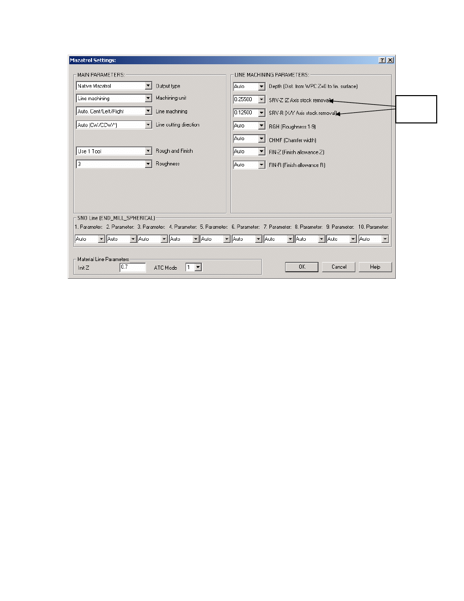
For example above we will change the output for SRV-Z and SRV-R to values shown
below:
33
Mastercam to Mazatrol Post-Processor Tutorial 8/18/2005
Change
values
A section of the Mazatrol output will be as below:
As you see the settings are output and shown in bold text below:
PNR MAT INITIAL-Z ATC MODE MULTI MODE MULTI FLG PITCH-X PITCH-Y
0 ALUMINUM 1.0 0 OFF
--------------------------------------------------------------------------------
UNO UNO DEPTH SRV-Z SRV-R RGH CHMF FIN-Z FIN-R
1 LINE-CTR 0.3000 .255 .125 3 * 0 0
SNO SNO NOM. NO. APRCH-X APRCH-Y TYPE ZFD DEP-Z WID-R C-SP FR M M
1 E-MILL 0.50 ? ? * G01 0.2550 * 1069 6.417 3 9
FIG PTN X Y R/0 I J P CNR
1 LINE 8.7198 9.2517
2 CCW 8.7600 9.4741 0.6350 8.1250 9.4741
3 LINE 8.7600 10.0514
4 CCW 8.2298 10.6777 0.6350 8.1250 10.0514
5 LINE 9.0401 11.1456
6 CCW 9.7400 10.7415 0.4601 9.5000 11.1340
7 LINE 9.7400 10.3717
8 CCW 9.2801 9.5752 0.4601 9.5000 9.9793
9 LINE 8.7198 9.2517
10 CCW 8.7577 9.4200 0.6350 8.1250 9.4741
11 LINE 8.9961 10.4767
12 LINE 8.8260 10.7017
13 LINE 8.9987 10.5517
14 LINE 8.7198 9.2517
--------------------------------------------------------------------------------
UNO UNO DEPTH SRV-Z SRV-R RGH CHMF FIN-Z FIN-R
2 LINE-CTR 0.6000 .255 .125 3 * 0 0 SNO SNO NOM. NO. APRCH-X APRCH-Y TYPE ZFD
DEP-Z WID-R C-SP FR M M
1 E-MILL 0.50 ? ? * G01 0.2550 * 1069 6.417 3 9
FIG PTN X Y R/0 I J P CN
34
Mastercam to Mazatrol Post-Processor Tutorial 8/18/2005
Exercise 2 - Mazatrol Style Pocket output for Pockets
In order to use the Mazatrol Pocket Styles we have to disable Mastercam’s Pocket
Roughing routines. The Mazatrol’s Pocketing styles will be based upon the Parameters
that are set within the controller itself. We will set the Mastercam Parameter Pages as
Follows for all the pocket toolpaths:
Set Misc. Values as below:
35
Mastercam to Mazatrol Post-Processor Tutorial 8/18/2005
Exercise 3 - Modifying Drill Cycles in Counter Boring
Group
In this section we will modify the Toolpath Group labeled as Counter Boring. If we were
to post this section each one of the tools would be in a separate UNO section a with a
drill cycle defined by what is shown currently in the Operations Manager. Therefore we
need to Group these operations together and also we need to make sure that the drill cycle
type is consistent. In this case we will set it to Mazatrol’s RGH CBOR.
We need to do the following:
1. Using EDIT COMMON PARAMETERS highlight the Counter Boring Group in the
Operations Manager set the Program # as follows:
36
Mastercam to Mazatrol Post-Processor Tutorial 8/18/2005
37
Mastercam to Mazatrol Post-Processor Tutorial 8/18/2005
2. We now need to make sure that for all the operations in this group the drill cycles are
set as follows:
38

Mastercam to Mazatrol Post-Processor Tutorial 8/18/2005
Note: We have used 6 tools in the previous section - the Mazatrol will allow this many
tools for this type of cycle - but the number of tools used by the mazatrol when manually
programming at the control is based upon internal calculations which reference Built-
In Parameters.
39
Mastercam to Mazatrol Post-Processor Tutorial 8/18/2005
Operations manager should then look as below
Exercise 4 - Modifying Drill Cycles in Tapping Group
As in the previous exercise we will modify the three operations grouped as .1900-24
TAP RH so that the output will be more efficient and readable as Mazatrol format. In
addition we will add an operation to create a chamfer before the final tapping operation.
We need to do the following:
1. Using EDIT COMMON PARAMETERS highlight the Tapping Group in the
Operations Manager set the Program # as follows:
40
Mastercam to Mazatrol Post-Processor Tutorial 8/18/2005
2. Set all Drill Cycles to TAP as below:
41
Mastercam to Mazatrol Post-Processor Tutorial 8/18/2005
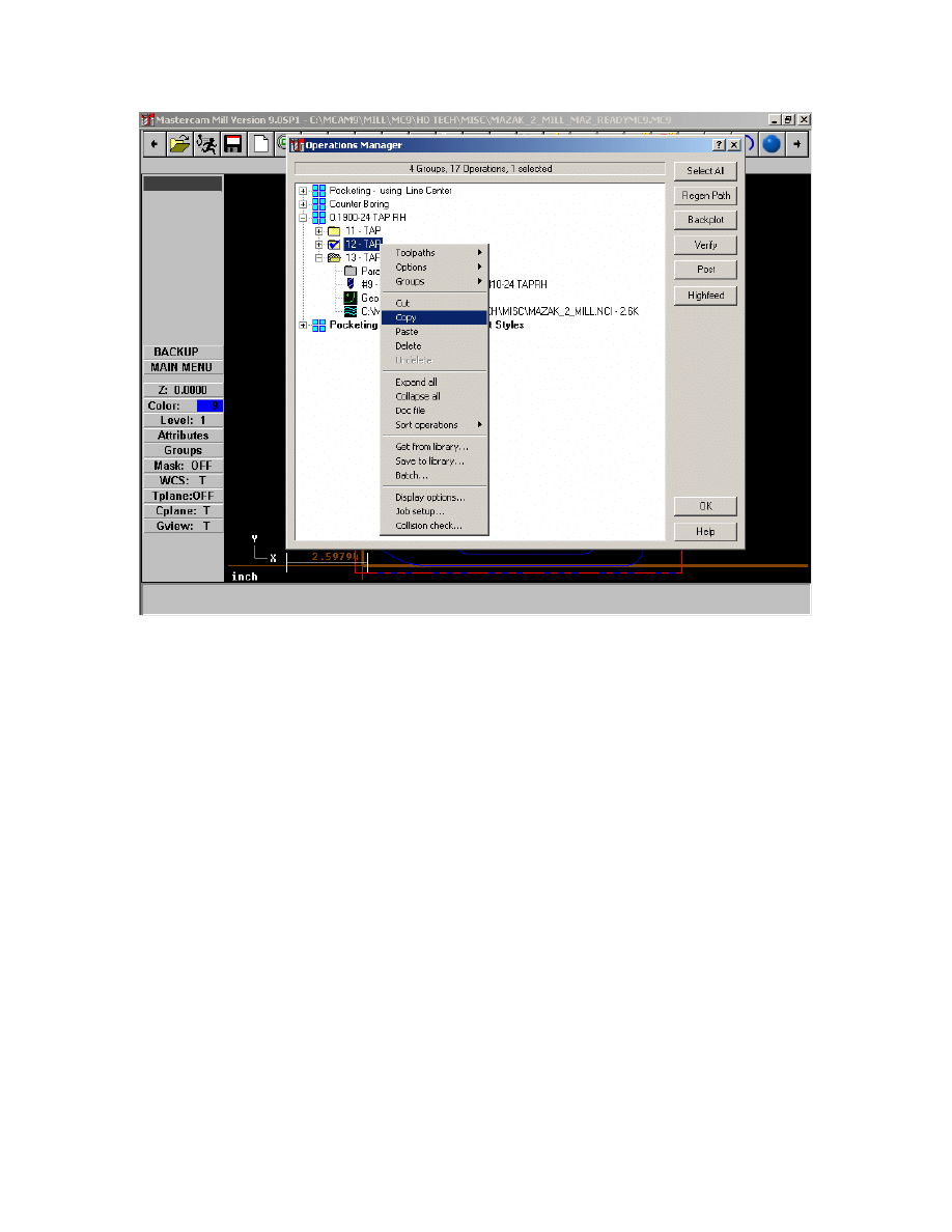
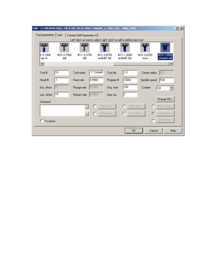
3.Now to add chamfering toolpath copy and paste the second operation within the group
as shown
42
Mastercam to Mazatrol Post-Processor Tutorial 8/18/2005
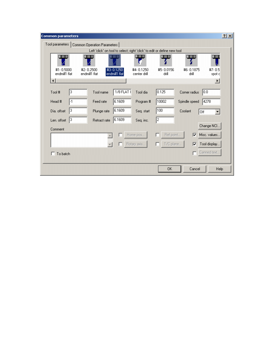
4. Then paste this operation so that it precedes the final tap operation.
5. Select Tool as shown.
43
Mastercam to Mazatrol Post-Processor Tutorial 8/18/2005
As you have copied the operation within the group the Program # is still correct as
shown.
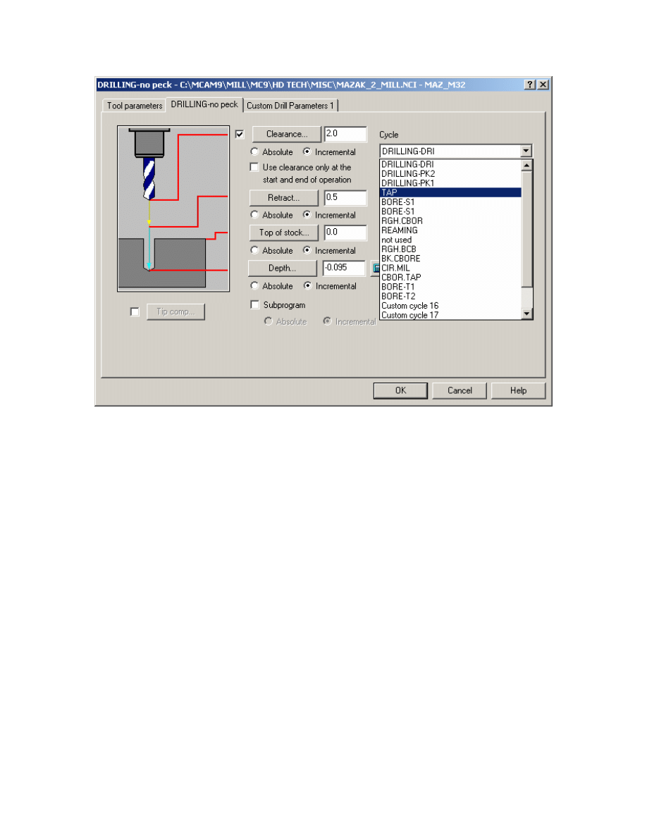
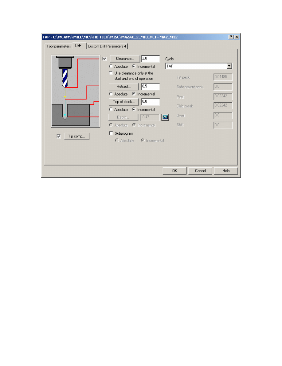
6. Set TAP page as follows:
44
Mastercam to Mazatrol Post-Processor Tutorial 8/18/2005
7. Select OK and REGEN path.
8. Save file and post to create Mazatrol Code.
45
Mastercam to Mazatrol Post-Processor Tutorial8/18/2005
Section 2 :Lathe
1
1
.
.
Programming a Basic Part.
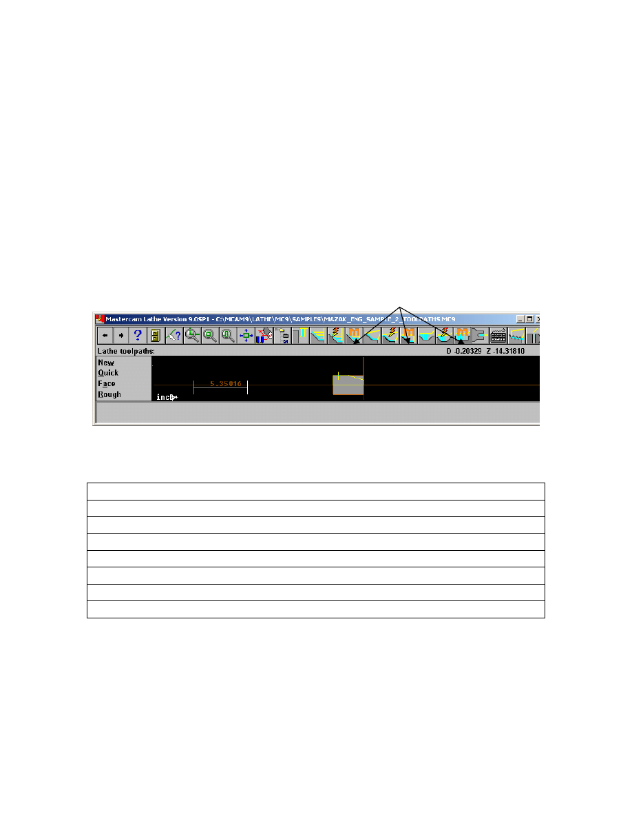
Mazatrol is designed to minimize the amount of information required to create a toolpath
- therefore with this Post Processor interface we provide toolbar icons as seen below
- these canned cycles are designated with the hopefully familiar ‘M’ for Mazak.
Obviously one can access these to create a toolpath but what is important to mention is
the following: When programming for Mazatrol output use
Mastercam
Mazatrol
Output
Face
- EDG; FCE
Canned Rough
- BAR; IN, OUT, FCE, BAK Also some GRV
Canned Finish -
BAR; IN, OUT, FCE, BAK
Canned Groove
- GRV; IN, OUT, FCE, BAK
Thread -
THR
Drill
-
DRL
Cutoff
-
GRV
46
Mastercam to Mazatrol Post-Processor Tutorial8/18/2005
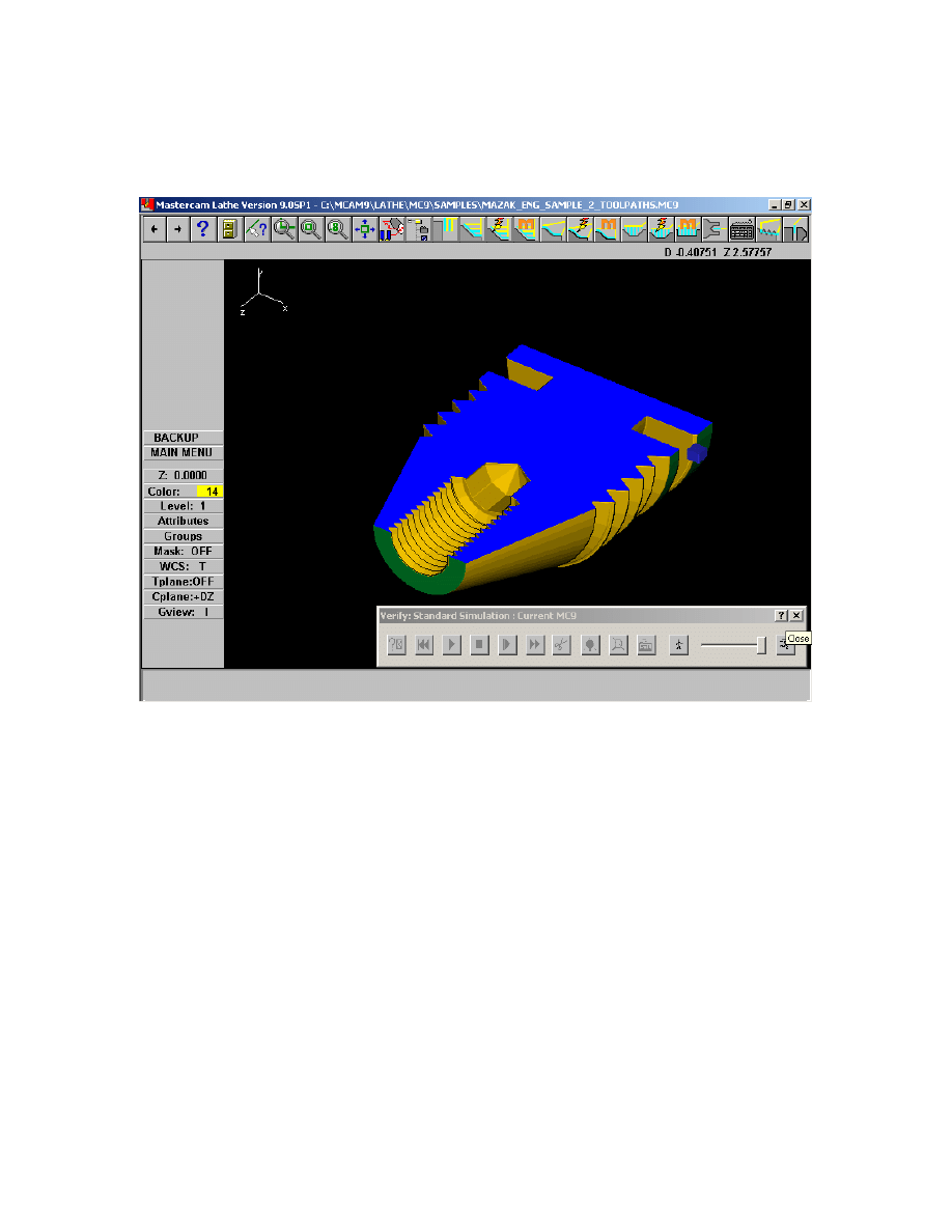
We will Rough and Finish outside profile, Drill and Thread ID then thread OD and final
step will be grooving OD.
Finished part is shown verified
47
Mastercam to Mazatrol Post-Processor Tutorial8/18/2005
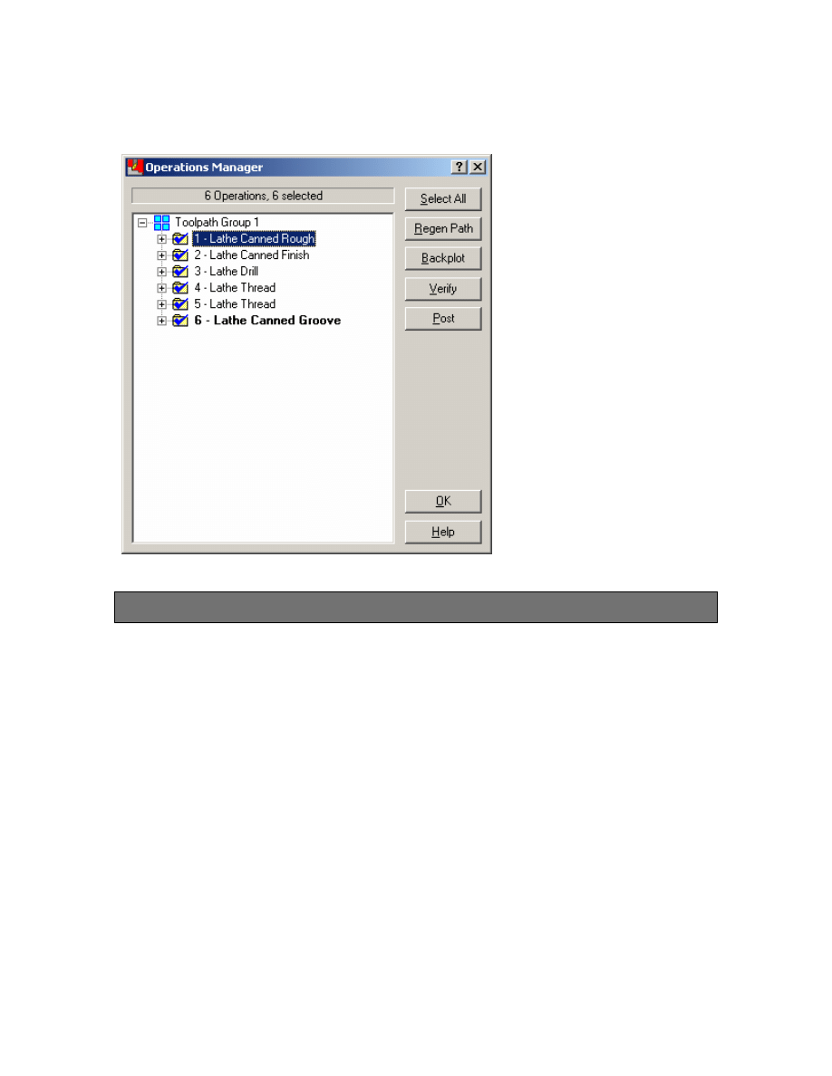
Operations List for Finished Part are listed below:
Exercise 1 - Opening the part file and Job Setup
1. Choose Main Menu, File, Get
2. Navigate to the folder with the tutorial parts.
3. Select Mazak_ENG_Sample_2.mc9; then choose Open.
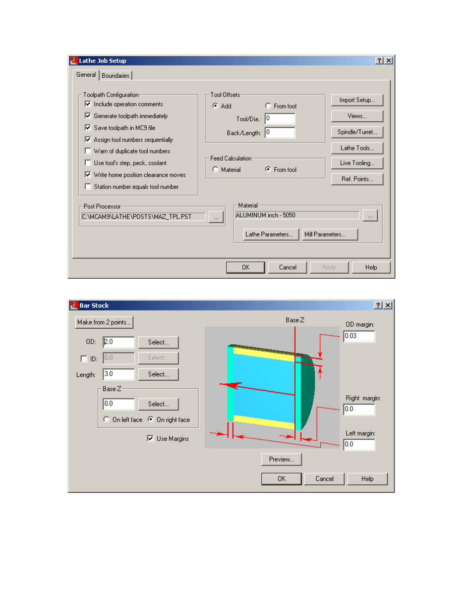
4. Choose, Main Menu, Toolpaths, Job Setup
5. Enter settings as shown.
48
Mastercam to Mazatrol Post-Processor Tutorial8/18/2005
Note: Job Setup settings will affect the first line of the mazatrol UNO 0 and MAT data
i.e. the material selected will be output and the OD will be OD-Max and Length will be
Length will be based on the values entered in the job setup see below:
49
Mastercam to Mazatrol Post-Processor Tutorial8/18/2005
The other settings will have to be manually entered by the user if desired either using the
editor (if available) or at the control.
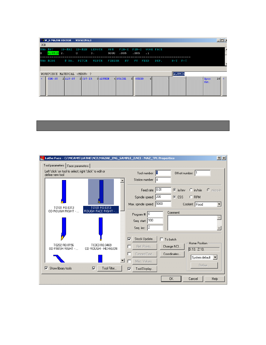
Exercise 2 - Creating Facing Toolpath
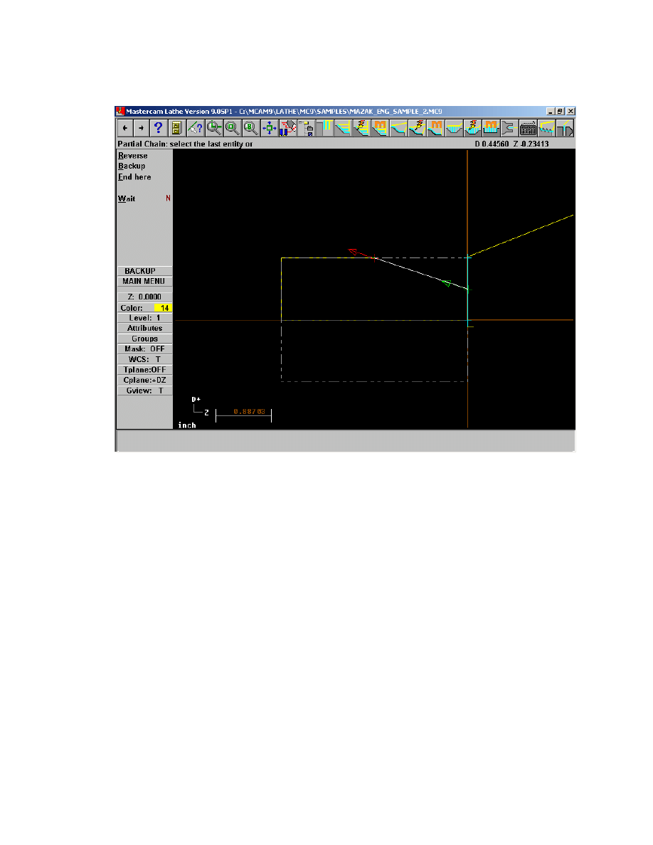
1. Choose Main Menu, Toolpaths, Face
2. Select outside profile as shown using chain
50
Mastercam to Mazatrol Post-Processor Tutorial8/18/2005
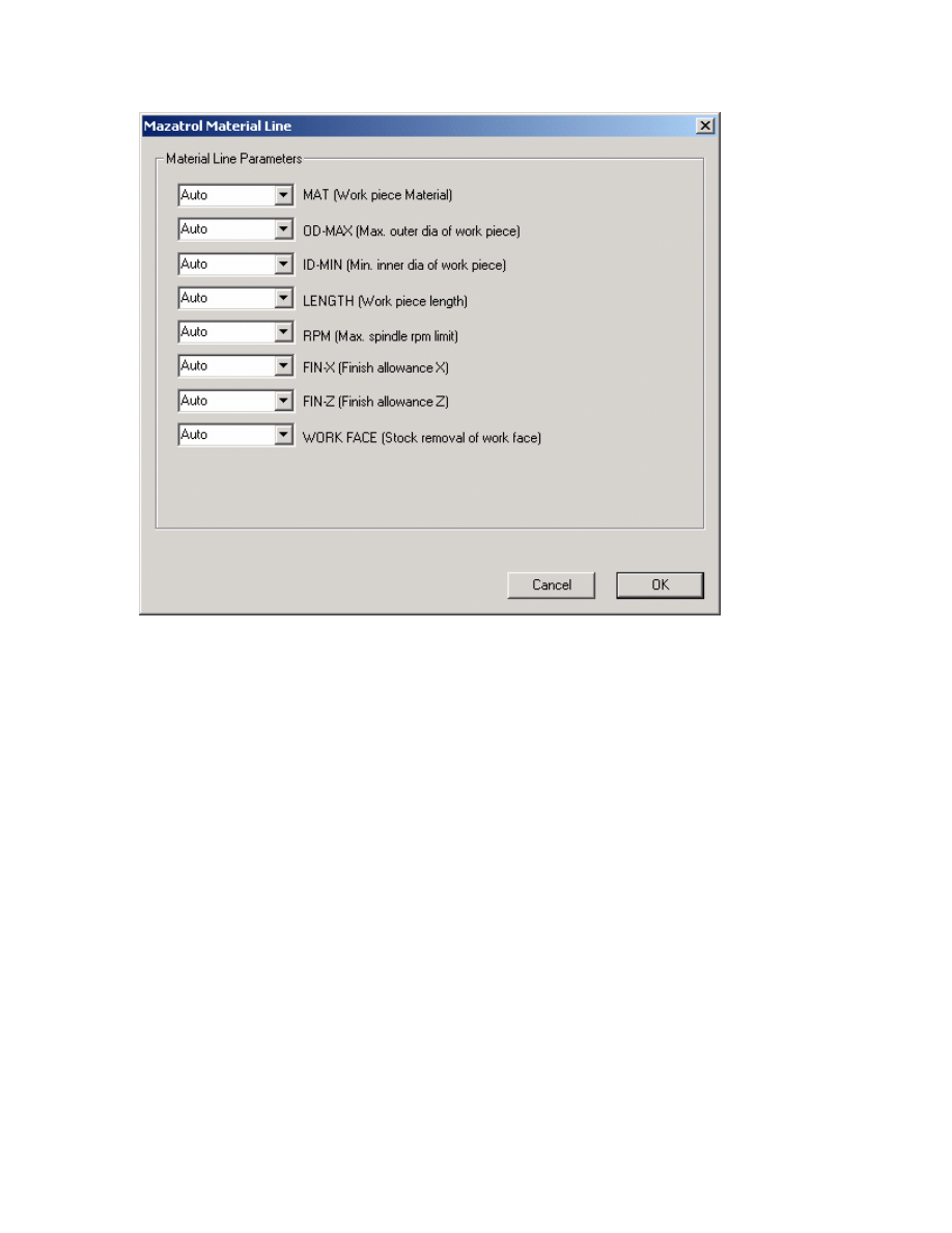
Important note: in Version 8.0.8 we introduced the access to the material line i.e. the
first line of the Mazatrol Program where the size and material of the stock are defined.
These values in some cases such as the length and diameter will overwrite previously
defined values in the Job Setup. See below:
Go back to the first parameter page of the Facing Toolpath and click on Misc. Values.
Then click on the Material Line. You should then see the following display:
51
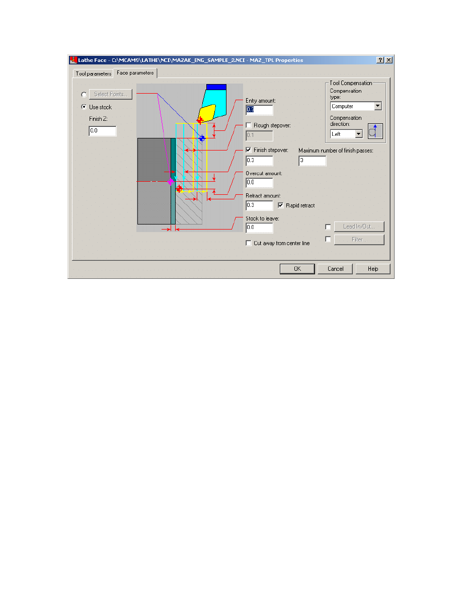
Mastercam to Mazatrol Post-Processor Tutorial8/18/2005
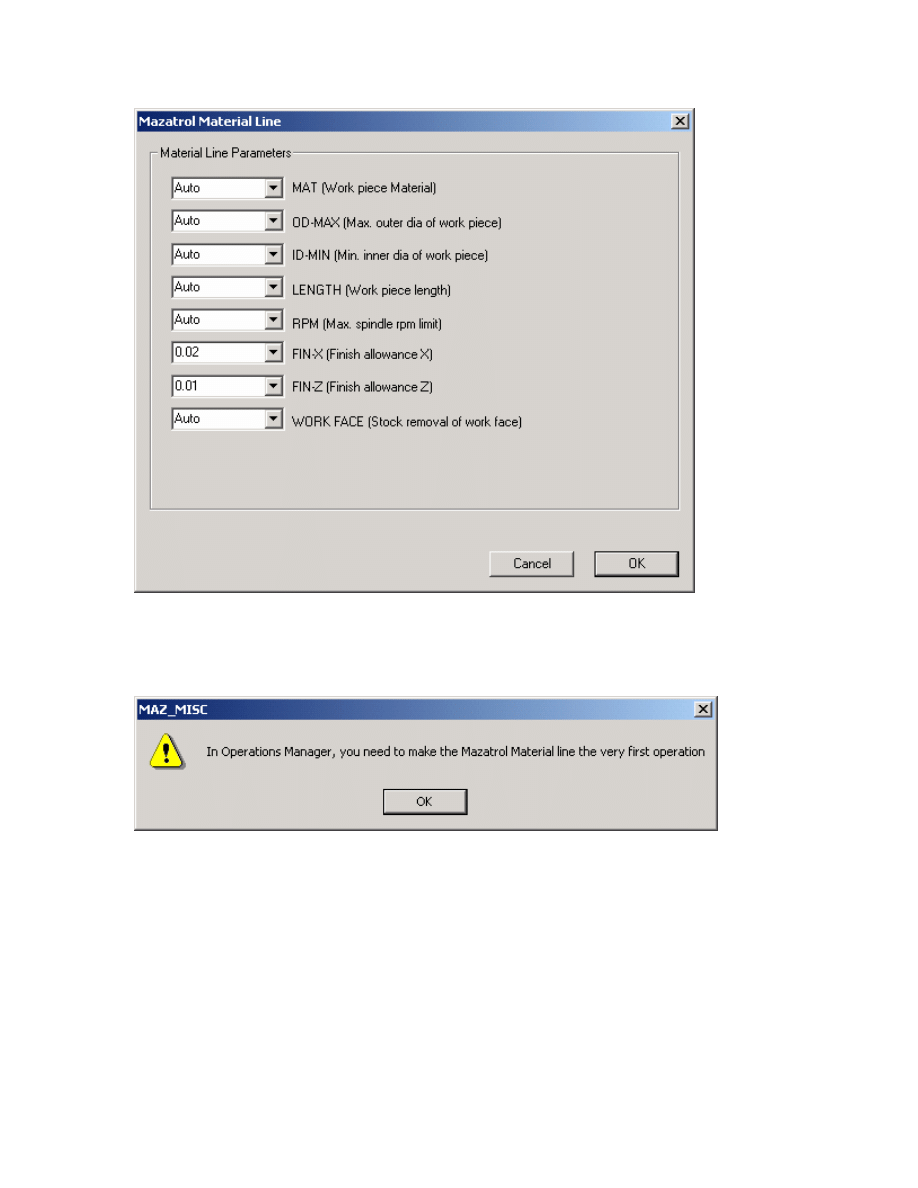
Let’s change the finish allowance values to FIN-X = 0.02 and FIN-Z = 0.01 by entering
in the dialog as shown below:
52
Mastercam to Mazatrol Post-Processor Tutorial8/18/2005
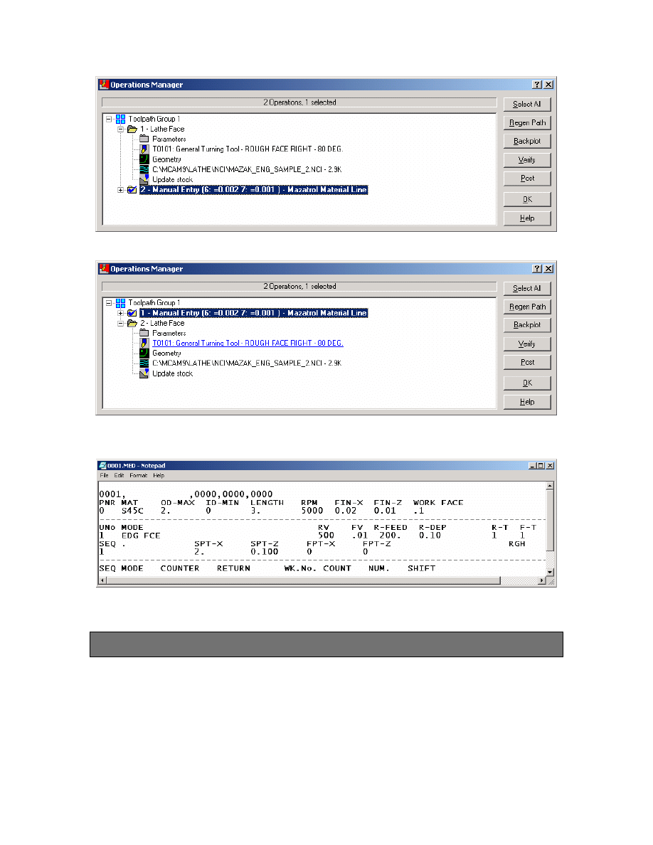
When you click OK you will get the following message
Click OK and in the Operations Manager Move this newly created Manual Operation to
be the first operation.
53
Mastercam to Mazatrol Post-Processor Tutorial8/18/2005
Move to here
Sample output for material line and facing :
Exercise 3 - Creating Rough and Finish Toolpath
Select the following:
1. Main Menu
2. Toolpaths
3 Canned Rough
54
Mastercam to Mazatrol Post-Processor Tutorial8/18/2005
4. Select Chain as Shown Below
5.
Set Parameters as in the following Roughing Param. Pages.
55
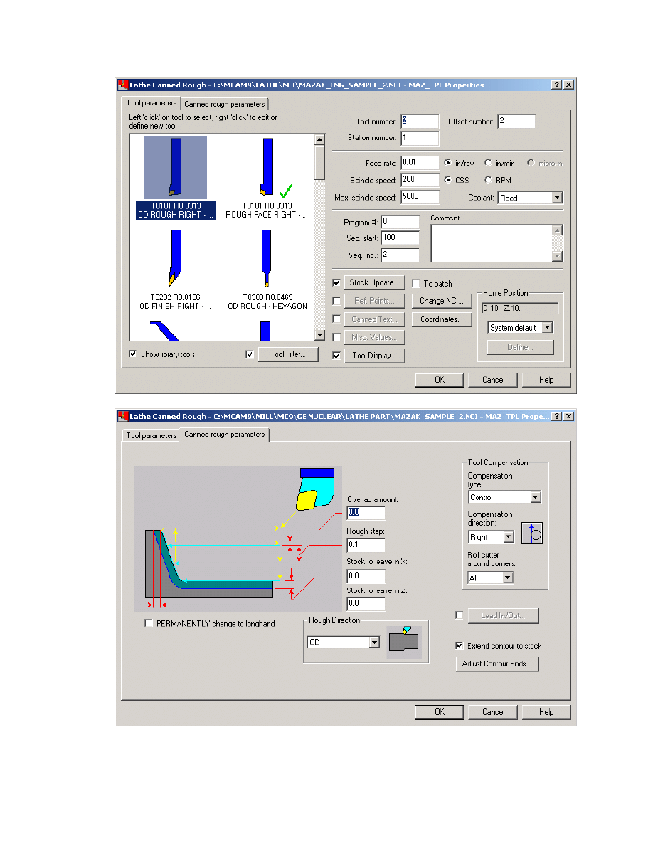
Mastercam to Mazatrol Post-Processor Tutorial8/18/2005
6.
Click on OK when completed
56
Mastercam to Mazatrol Post-Processor Tutorial8/18/2005
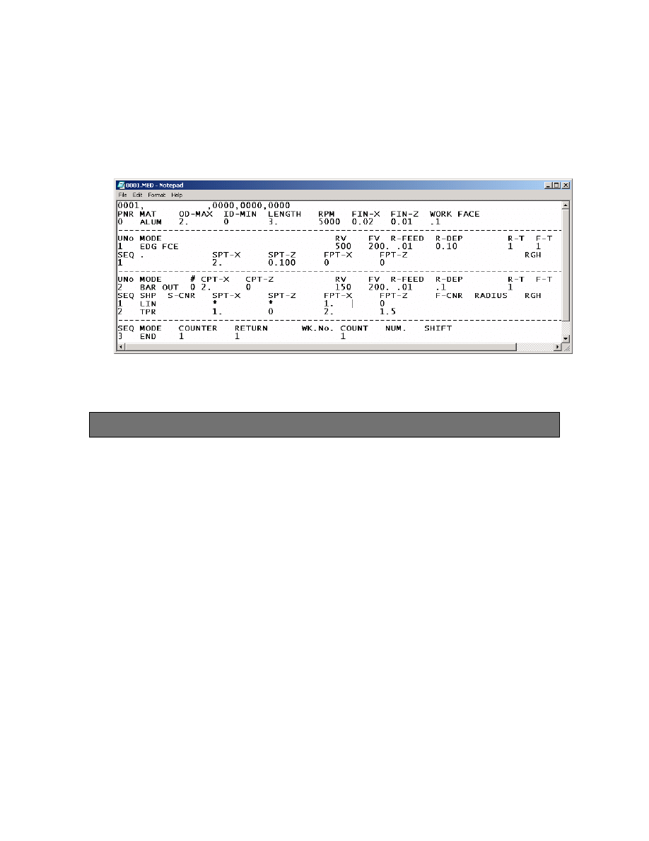
If we were to post for output now, we would get window as shown below. We
provide this to illustrate our progress. When we have completed the complete part
program we will then document how to run the post and then send the program to the
control.
Exercise 4 - Creating Drill Toolpaths
To create Drill Toolpaths select the following:
1. Main Menu
2. Toolpaths
3. Drill - set Param. Pages as shown on the following pages
57
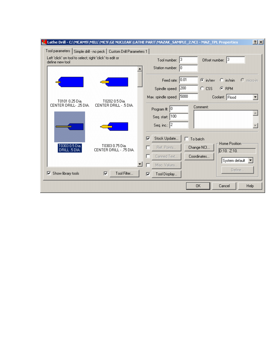
Mastercam to Mazatrol Post-Processor Tutorial8/18/2005
2. Select Tool as shown
3. Set next page as shown.
58
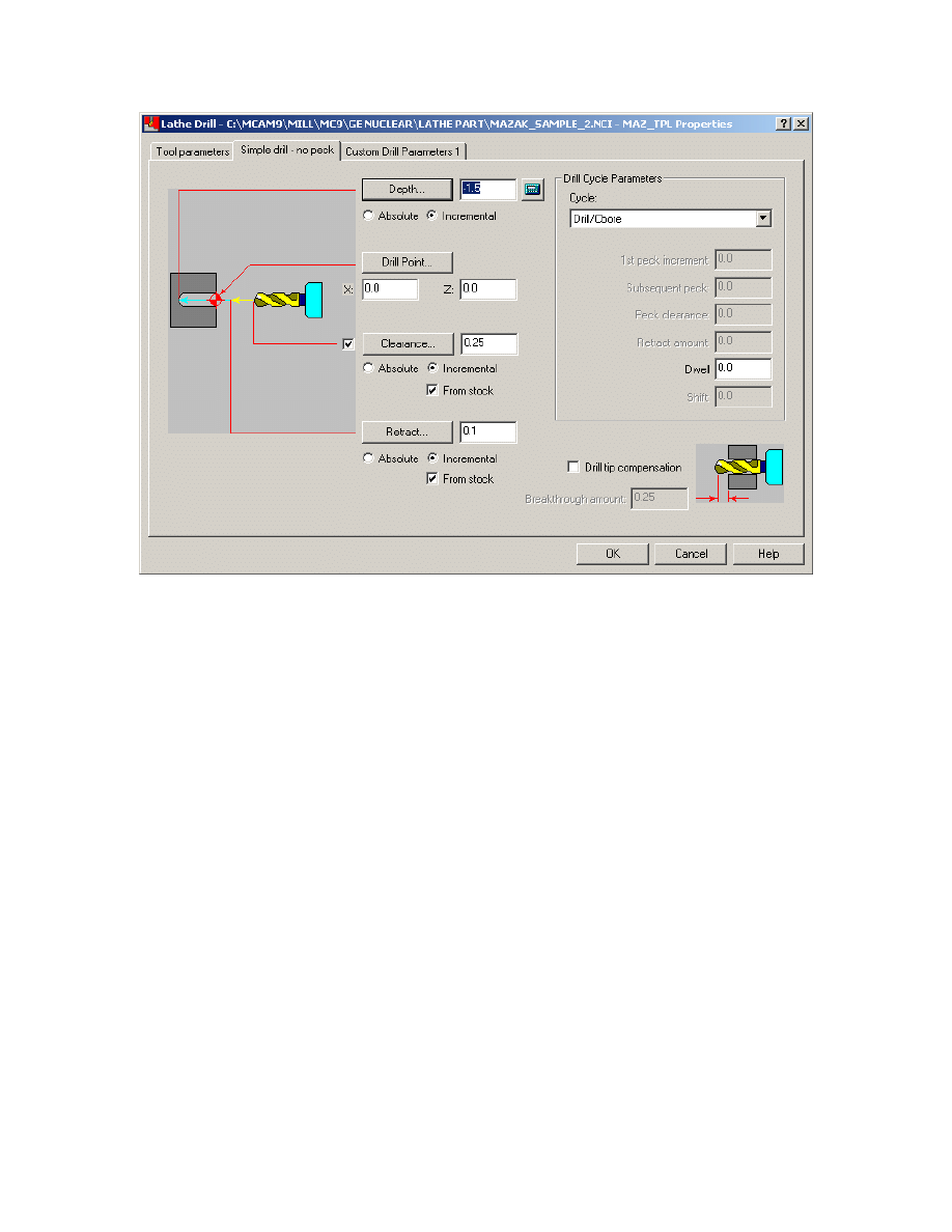
Mastercam to Mazatrol Post-Processor Tutorial8/18/2005
4. Click on OK when done
5. Set Misc. Values as shown
59
Mastercam to Mazatrol Post-Processor Tutorial8/18/2005
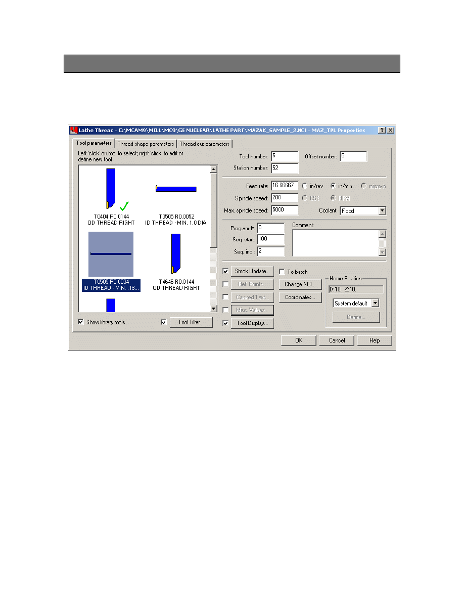
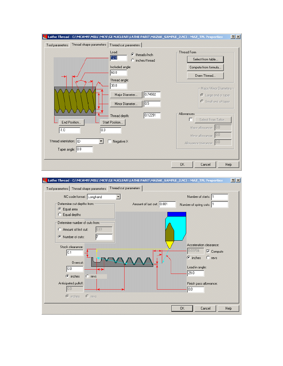
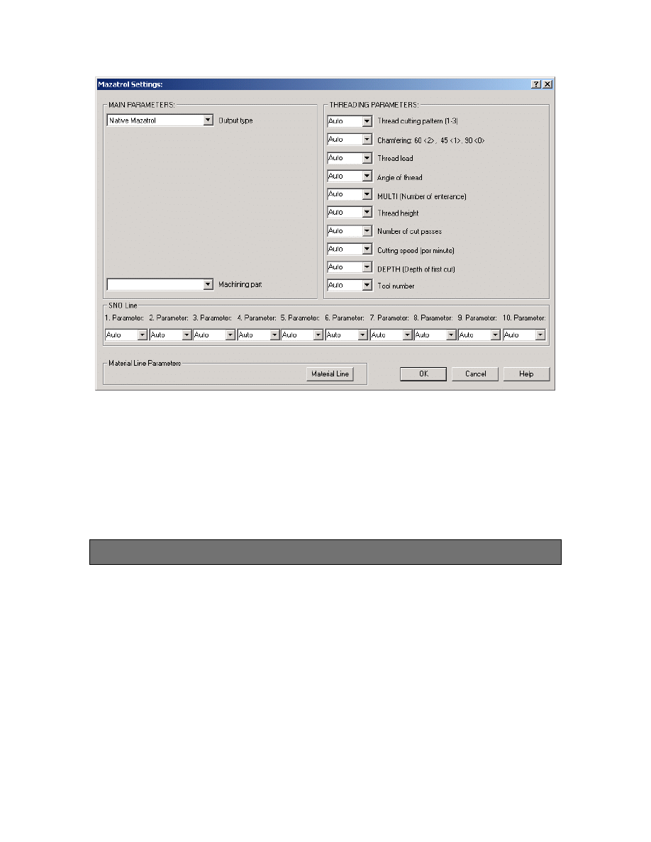
Exercise 5 - Threading Toolpaths
We will now Thread the ID
1. Set Thread Parameters as shown on the following pages.
60
Mastercam to Mazatrol Post-Processor Tutorial8/18/2005
61
Mastercam to Mazatrol Post-Processor Tutorial8/18/2005
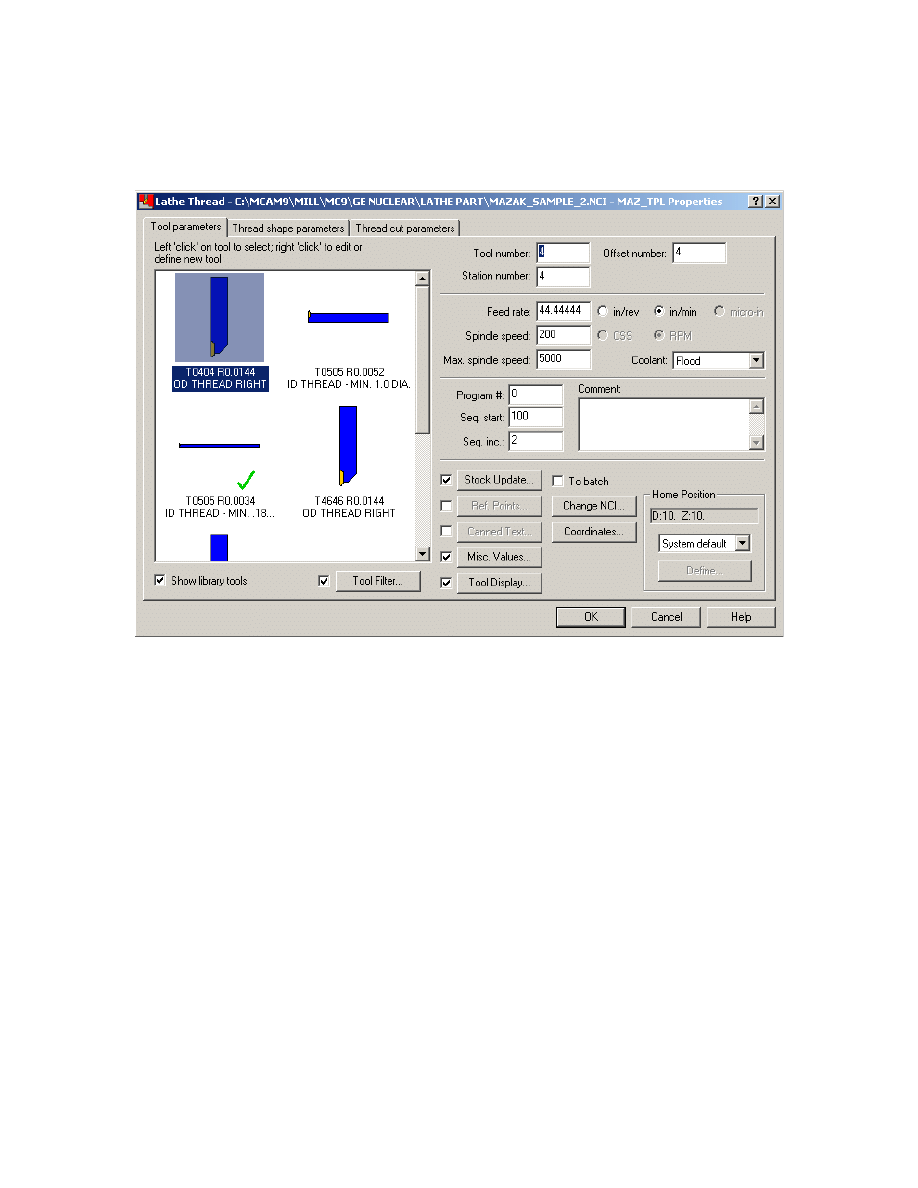
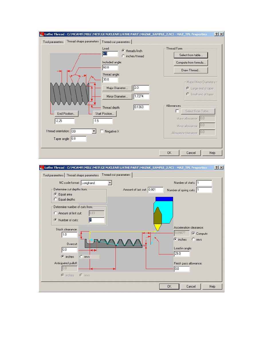
We will now Thread the OD, set the Parameters as shown below
62
Mastercam to Mazatrol Post-Processor Tutorial8/18/2005
63
Mastercam to Mazatrol Post-Processor Tutorial8/18/2005
Note: As you may notice – the Misc. Values dialog box allows every setting in the
mazatrol SNO line and UNIT (UNO) line to be set by the user and override the
automatically set values output by the post-processor.
Select OK when done.
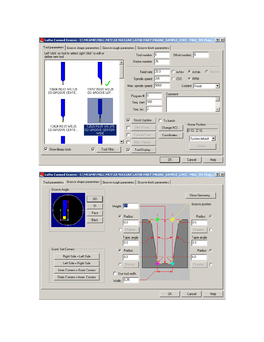
Exercise 5 - Creating Groove Toolpath
As with the Roughing and Finishing toolpaths it is generally unnecessary to have both a
rough and a finish operation programmed in mastercam to get the correct output in
Mazatrol
We will now create a 1 point groove on the OD.
Select the following:
1. Main Menu
2. Toolpaths
3. Canned Groove
4. Select 1 pt
5. Click pt shown on OD
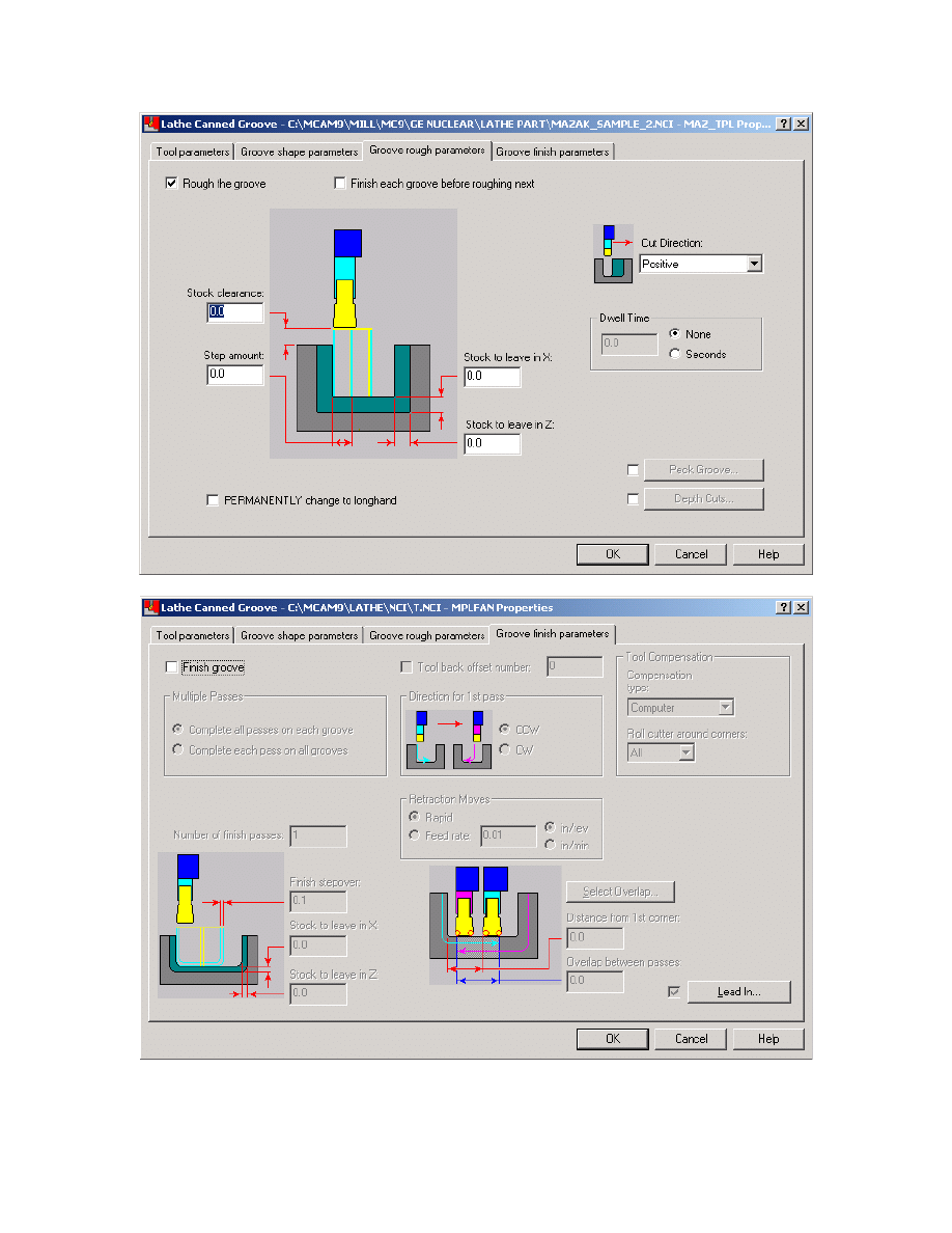
6. Set Parameter Pages as shown
64
Mastercam to Mazatrol Post-Processor Tutorial8/18/2005
65
Mastercam to Mazatrol Post-Processor Tutorial8/18/2005
We do not need to select a finish for grooving. So set as shown above
66
Mastercam to Mazatrol Post-Processor Tutorial8/18/2005
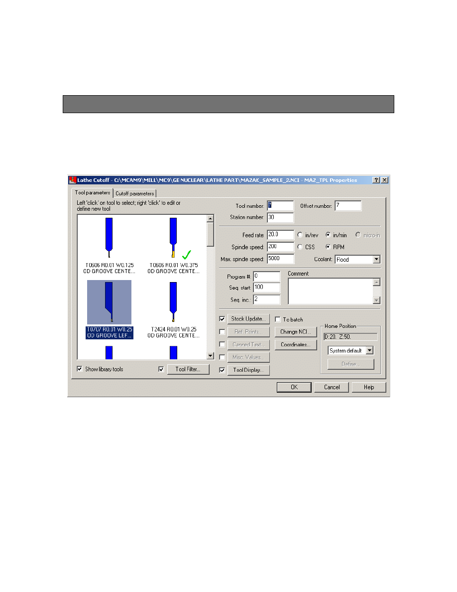
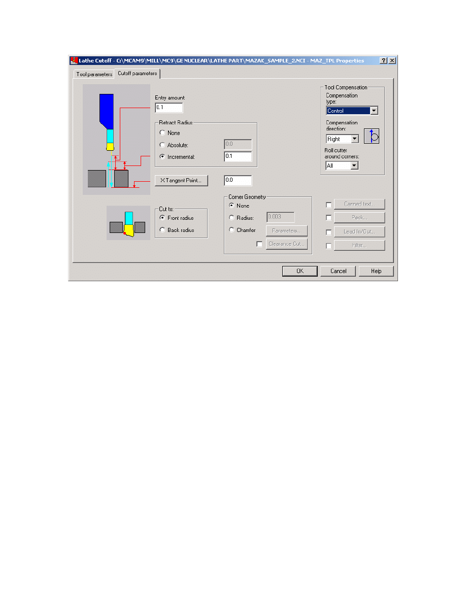
Exercise 6 - Creating Cutoff Toolpath
We will now finish the part by creating a cutoff operation.
Set Parameter Pages using Cutoff Toolpath
67
Mastercam to Mazatrol Post-Processor Tutorial8/18/2005
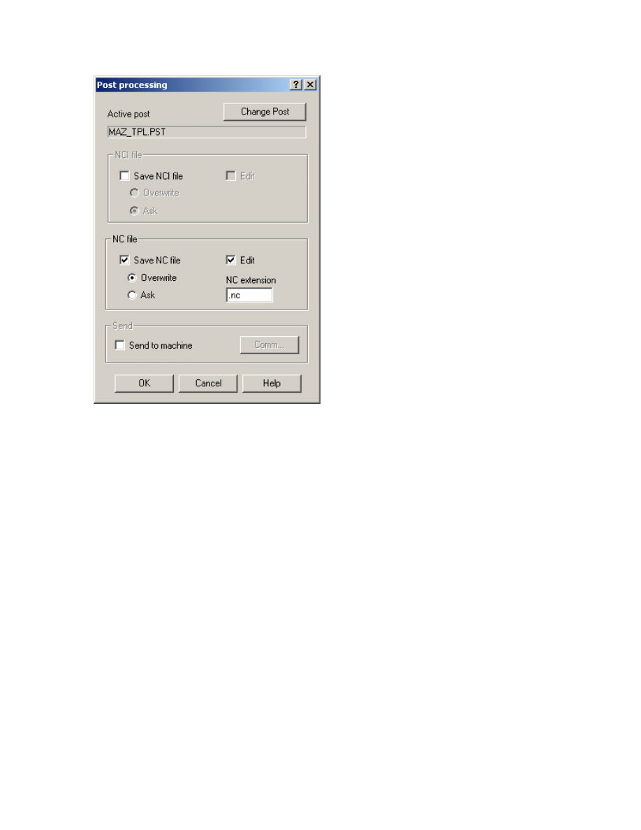
6. Select Done. This should return you to the operations manager. Select Post
Modify settings as shown below. (In this example we are using the TPlus post-processor
shown as MAZ_TPL.PST. Yours may vary but all the Mazatrol Post-Processors will have
the format of MAZ_XXX.PST)
68
Mastercam to Mazatrol Post-Processor Tutorial8/18/2005
7. Select OK. The file name dialog should then appear as shown below:
Note: We do not need to create an NC file but Mastercam needs to have this setting so
that the post-processor can function
8. Click Save.
69
Mastercam to Mazatrol Post-Processor Tutorial8/18/2005
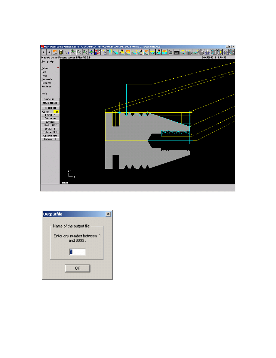
The Mazak Menu will then appear in place of the Mastercam Main Menu
10. From this menu select Run postp. to run the Mazatrol Post.
11. Select a number between 1 and 9999 and hit OK. This will be the program number
for your Mazatrol output file.
70
Mastercam to Mazatrol Post-Processor Tutorial8/18/2005
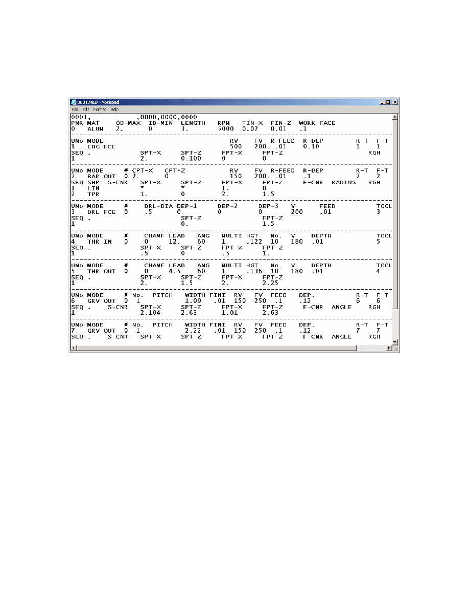
You should then see output as shown below (output below is shown as a Notepad
window – if you have purchased the Editor and you have the Editor set to Yes in the
Mazatrol Menu the output will open up in the Mazatrol Editor)
12. Close this window.
We will then send this program to the controller
13. From the Mazatrol Menu select Transmit.
71
Mastercam to Mazatrol Post-Processor Tutorial8/18/2005
15. If the settings are correct and you are using the Built in DNC click Transmit.
This is the progress bar.
72

Mastercam to Mazatrol Post-Processor Tutorial8/18/2005
To complete the download complete the following steps at
The Mazak Controller.
¾ PROGRAM-LIST or INDEX
¾ DATA IN/OUT
¾ CMT-NC
¾ INPUT
¾ ENTER THE PROGRAM NUMBER AND SELECT INPUT
¾ HIT START
You should then see the file being downloaded by a blue bar filling the progress bar
shown above.
Congratulations! You have created your first mastercam to mazatrol program.
16. Hit esc once the Progress Bar is completed.
17 Hit esc to get back to Mastercam Main Menu.
Save File
73

Mastercam to Mazatrol Post-Processor Tutorial8/18/2005
Appendix
Working with the Misc. Values Dialog to modify /override
automatically generated output.
There will be times when you will wish to adjust the output at the mastercam
programming stage or when a part has been programmed for a non-mazatrol control. As
has been discussed earlier any value of the SNO and UNO lines can be overridden
through the Misc. Values Page.
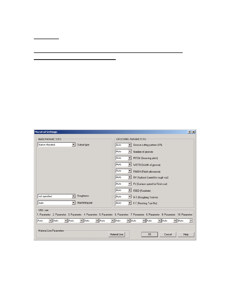
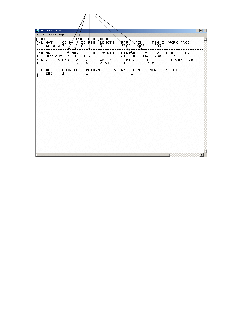
In the following example we will take the automatically generated groove of the
previously programmed part and enter values which will then appear in the mazatrol
code.
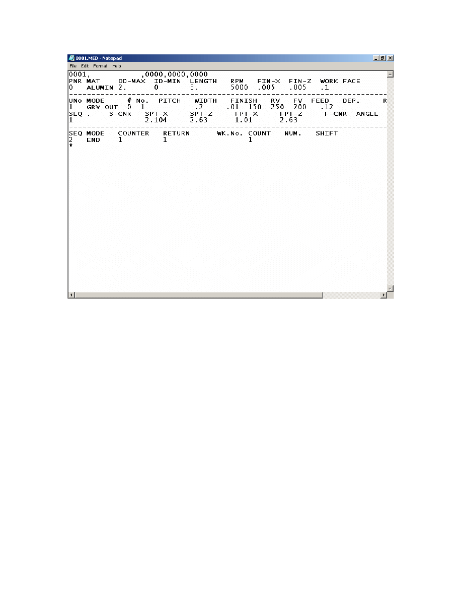
Below is Current Misc. values Dialog with current Auto Settings and then outputted
code.
75
Mastercam to Mazatrol Post-Processor Tutorial8/18/2005
We will adjust the following:
We want a different grooving pattern say #2 Right-tapered grooves
Maybe multiple grooves based off of original No.of 3 with a Pitch of 1.5
Maybe different values for feeds 200 for RV and 166 for FV
We would modify the Misc. Values as shown
76
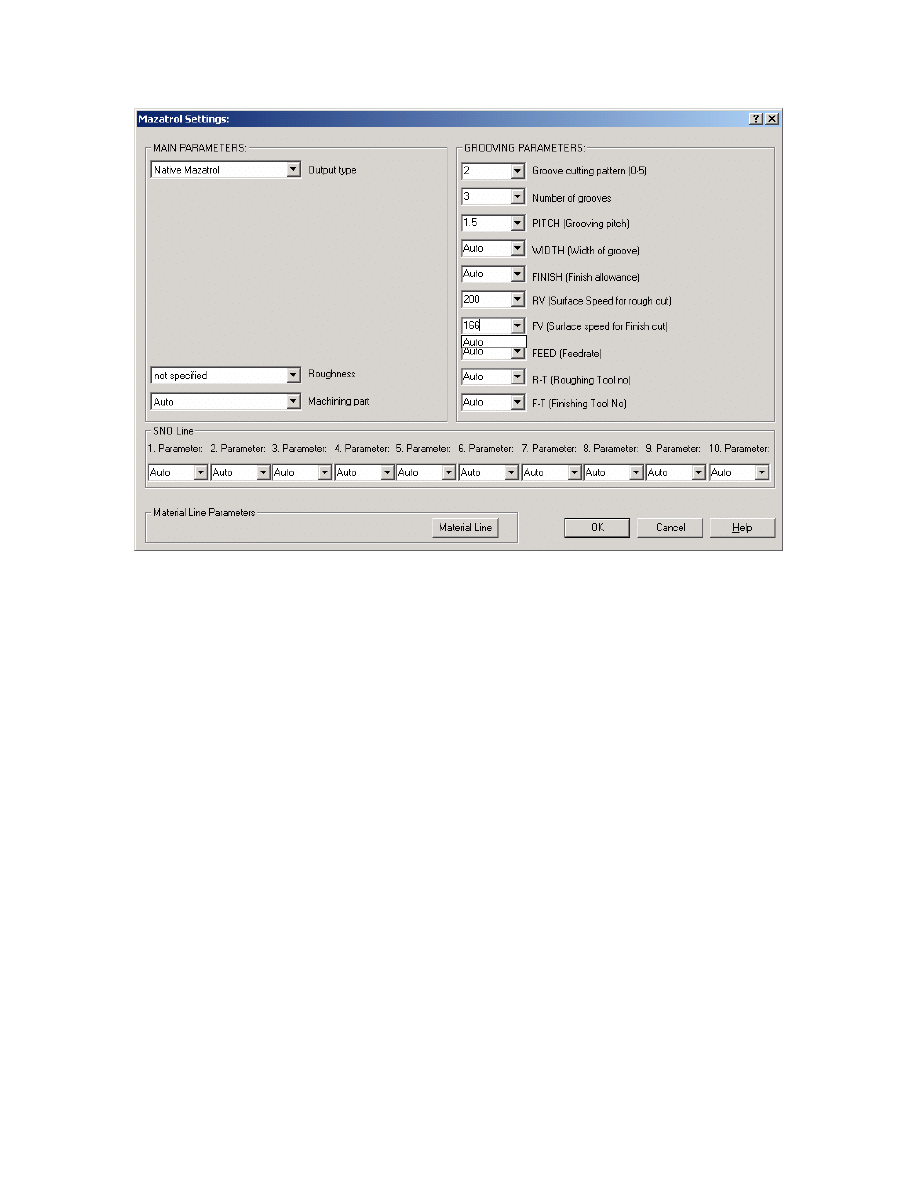
Mastercam to Mazatrol Post-Processor Tutorial8/18/2005
You can then see in the output below that those setting are now in transferred over.
77
Mastercam to Mazatrol Post-Processor Tutorial8/18/2005
This can be done with every toolpath and operation and allows complete control to the
programmer.
FOR ADDITIONAL INFORMATION ON THE USE OF THIS PRODUCT CONTACT:
Camaix USA
1515 South Mint St Suite C
Charlotte, NC 28203
704- 342-9292
INFOUSA@CAMAIX.COM
78
Document Outline
- Section 2. Programming a Lathe Part
- Section 1 - Mill
- Exercise 1 - Opening the part file
- Save File as Mazak_1_Mill_1.mc9
- Exercise 1 - Creating Pocket Toolpath
- Exercise 2 - Creating Drill Toolpaths with Multiple Tools
- Exercise 1 - Opening Part File
- Exercise 2 - Line-Center output for Pockets
- Exercise 2 - Mazatrol Style Pocket output for Pockets
- Exercise 3 - Modifying Drill Cycles in Counter Boring Group
- Exercise 4 - Modifying Drill Cycles in Tapping Group
- Exercise 1 - Opening the part file and Job Setup
- Exercise 5 - Creating Groove Toolpath
- Exercise 6 - Creating Cutoff Toolpath
Wyszukiwarka
Podobne podstrony:
Mastercam Post Processor Tutorial 1(1)
Mastercam Post Processor Tutorial 1
3 Data Plotting Using Tables to Post Process Results
2 Advanced X Sectional Results Using Paths to Post Process
3 Data Plotting Using Tables to Post Process Results
2 Advanced X Sectional Results Using Paths to Post Process
Myślenie lub rozumowanie to złożony ciągły proces zachodzący w mózgu
2014 05 29 Jeśli Jezus to tylko poważnie Proces Urbana
guide to debt recovery process
Masterspy to Grassley Wyden on Continuous Spying
Rhino Post Processor User Manual
inverter 2002 chapter 4 DC to AC conversion inverter tutorial
Halpern A logical approach to reasoning about uncertainty a tutorial (1995) [sharethefiles com]
Edukacja ustawiczna dorosłych jest to proces systematycznego uczenia się andragogika
Edukacja zdrowotna w szkole jest to proces dydaktyczno
Proces pielęgnowania omówienie co to jest
EURPOEJSKIE PROCESY INTEGRACYJNE, Akademia Morska Szczecin Nawigacja, uczelnia, AM, AM, nie kasować
więcej podobnych podstron