STEEL INDUSTRIAL HALL - LATERAL SYSTEM DESIGN
A. Data:
span of the girder:
the level of the head of the column:
the spacing of main columns:
length of the hall:
the cover:
steel:
localization:
L
27m
:=
H
13.5m
:=
a
6m
:=
A
78m
:=
sandwich panel
S355
Warszawa
1. Composition of loads
1.1 Permanent actions - scheme 1
a) self-weight of girder and roof structure:
Gg
7.69kN
:=
(indirect node)
Ggc
4.7kN
:=
(extreme node)
b) self-weight of walls:
self-weight of sandwich panel
BALEXTHERM-PU-W-ST 100mm
gk
0.124
kN
m
2
:=
Z shape 20x20x2:
gz
0.003
kN
m
:=
G0
gk a
⋅
gz
+
0.747
kN
m
⋅
=
:=
eccentricity of the load of covering:
e0
0.5 100
⋅
mm
200mm
+
0.5 300
⋅
mm
+
0.4 m
=
:=
bending moment evenly distributed on the length of column:
M0
G0 e0
⋅
0.299
kN m
⋅
m
⋅
=
:=
c) self-weight of the column:
Initially was accepted I-section HEB300 with the self-weight
gs
117
kg
m
:=
Gs
1.17
kN
m
:=
1.2 Variable loads
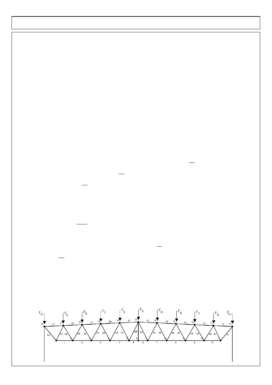
1.2.1 Snow load - scheme 2
Fs
11.66kN
:=
(indirect node)
Fsc
7.13kN
:=
(extreme node)
STEEL INDUSTRIAL HALL - LATERAL SYSTEM DESIGN
1.2.2 Wind load
peak velocity pressure:
qp
0.742
kN
m
2
:=
Systems of load
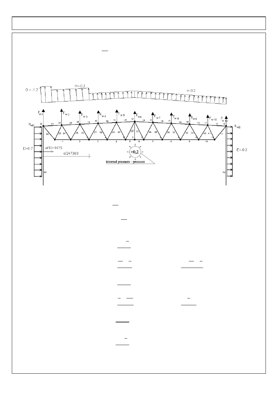
SYSTEM 1 - wind from the side
Scheme 3: wind from left side and internal pressure
Values of load distributed over walls:
qwD3
0.85 cs cd
⋅
qp
⋅
0.7
⋅
wiP
−
(
)
a
⋅
1.892
kN
m
⋅
=
:=
qwE3
0.85 cs cd
⋅
qp
⋅
0.3
−
(
)
⋅
wiP
−
a
⋅
1.892
−
kN
m
⋅
=
:=
Values of resultant forces concentrated in nodes of upper chord:
Fw13
cs cd
⋅
weG
⋅
wiP
−
(
)
c
b
2
+
cos
α
( )
l
⋅
⋅
10.297
−
kN
⋅
=
:=
node 22
Fw23
cs cd
⋅
weG
⋅
wiP
−
(
)
e
10
b
2
−
cos
α
( )
l
⋅
⋅
cs cd
⋅
weH
⋅
wiP
−
(
)
b
e
10
−
b
2
+
cos
α
( )
l
⋅
⋅
+
11.11
−
kN
⋅
=
:=
node 21
Fw33
cs cd
⋅
weH
⋅
wiP
−
(
)
b
cos
α
( )
l
⋅
⋅
10.832
−
kN
⋅
=
:=
node 20
Fw43
cs cd
⋅
weH
⋅
wiP
−
(
)
e
2
5 b
⋅
2
−
cos
α
( )
l
⋅
⋅
cs cd
⋅
weI
⋅
wiP
−
(
)
b
2
cos
α
( )
l
⋅
⋅
+
4.914
−
kN
⋅
=
:=
node 19
Fw53
cs cd
⋅
weI
⋅
wiP
−
(
)
b
cos
α
( )
l
⋅
⋅
4.814
−
kN
⋅
=
:=
nodes 18 - 13
Fw63
cs cd
⋅
weI
⋅
wiP
−
(
)
c
b
2
+
cos
α
( )
l
⋅
⋅
2.942
−
kN
⋅
=
:=
node 12
Scheme 4: wind from right side and internal pressure
Mirror of scheme 3
STEEL INDUSTRIAL HALL - LATERAL SYSTEM DESIGN
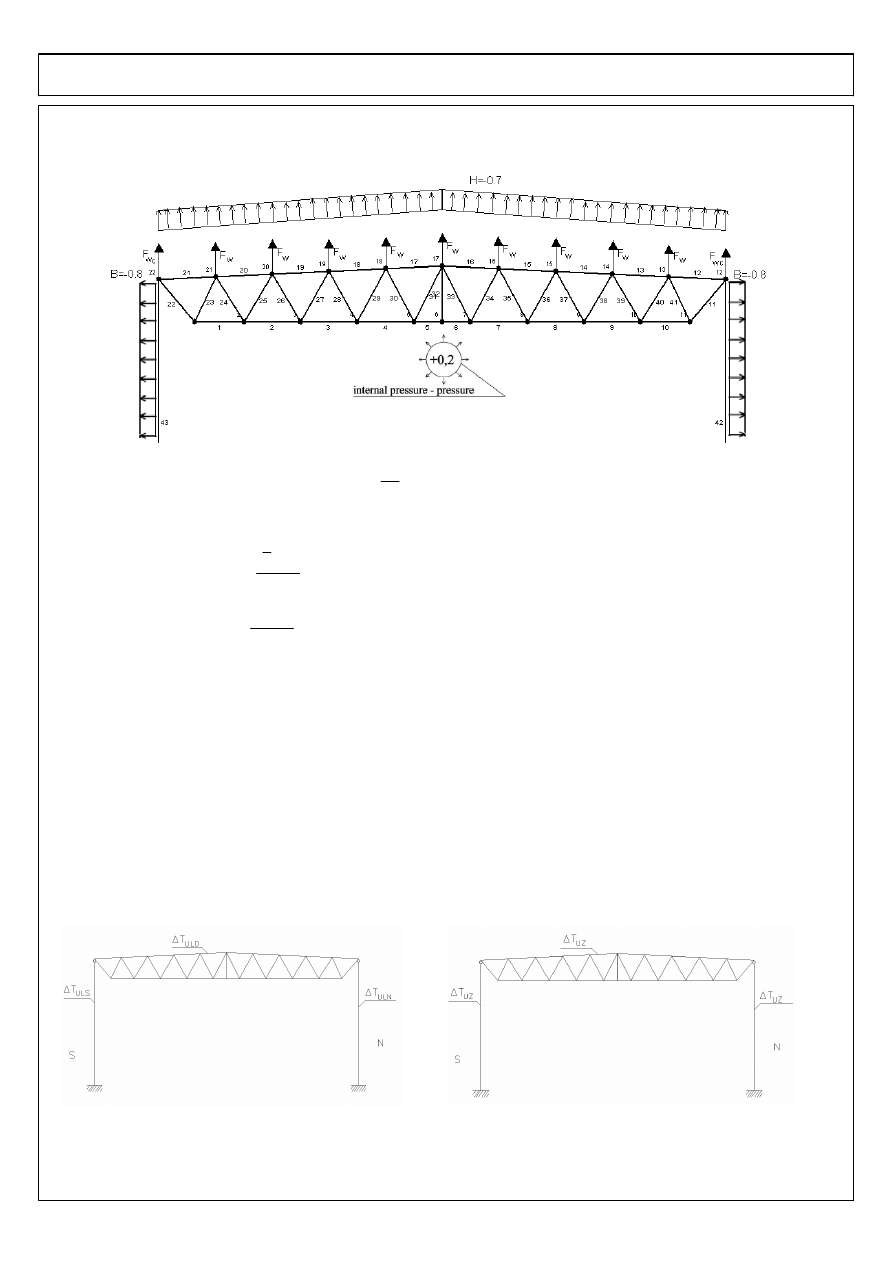
SYSTEM 2 - wind from the front
Scheme 5: wind from the front and internal pressure
Values of load distributed over walls:
qwB3
0.85 cs cd
⋅
qp
⋅
0.8
−
(
)
⋅
wiP
−
a
⋅
3.784
−
kN
m
⋅
=
:=
Resultant concentrated forces in nodes of upper chord:
Fwc5
cs cd
⋅
weH
⋅
wiP
−
(
)
b
2
c
+
cos
α
( )
l
⋅
⋅
6.619
−
kN
⋅
=
:=
Fw5
cs cd
⋅
weH
⋅
wiP
−
(
)
b
cos
α
( )
l
⋅
⋅
10.832
−
kN
⋅
=
:=
1.2.3 Thermal load (first part of project)
The uniform component of the temperature:
- in summer for elements and surfaces situated from the north-east side
∆TULN
23deg
:=
- in summer for elements and surfaces situated from the south-west side
∆TULS
37deg
:=
- summer for the roof
∆TULD
43deg
:=
- in winter for the all construction
∆TUZ
9.5
−
deg
:=
Scheme 6: the thermal load in summer
Scheme 7: the thermal load in winter
STEEL INDUSTRIAL HALL - LATERAL SYSTEM DESIGN
RM WIN
2. Column
2.1 Combination of actions
COMBINATION 1 - dimensioning the column (dead load, wind action from right side, snow load)
γGjsup Gkjsup
⋅
γQ1 Qk1
⋅
+
γQ2 ψQ2
⋅
Qk2
⋅
+
NEd
1.35 40.8
⋅
kN
1.5 26.4
⋅
kN
+
1.5 0.5
⋅
59.5
⋅
kN
+
139.31 kN
⋅
=
:=
MEd
1.35 7.5
⋅
kNm
1.5 43.1
⋅
kNm
+
1.5 0.5
⋅
0.4
⋅
kNm
+
75.08 kNm
⋅
=
:=
VEd
1.35 0.3
⋅
kN
1.5 12.8
⋅
kN
+
1.5 0.5
⋅
0
⋅
kN
+
19.61 kN
⋅
=
:=
COMBINATION 2 - maximum bending moment (dead load, wind action from left side, snow load, winter)
γGjsup Gkjsup
⋅
γQ1 Qk1
⋅
+
γQi ψQi
⋅
Qki
⋅
(
)
∑
+
NEd
1.35 40.8
⋅
kN
1.5 26.4
⋅
kN
+
1.5 0.5
⋅
59.5
⋅
kN
+
1.5 0.6
⋅
0
⋅
kN
+
139.31 kN
⋅
=
:=
MEd
1.35 7.5
⋅
kNm
1.5 43.1
⋅
kNm
+
1.5 0.5
⋅
0.4
⋅
kNm
+
1.5 0.6
⋅
1.3
⋅
kNm
+
76.25 kNm
⋅
=
:=
VEd
1.35 0.3
⋅
kN
1.5 12.8
⋅
kN
+
1.5 0.5
⋅
0
⋅
kN
+
1.5 0.6
⋅
0.1
⋅
kN
+
19.7 kN
⋅
=
:=
COMBINATION 3 - maximum axial force (dead load, snow load)
γGjsup Gkjsup
⋅
γQ1 Qk1
⋅
+
NEd
1.35 40.8
⋅
kN
1.5 59.5
⋅
kN
+
144.33 kN
⋅
=
:=
MEd
1.35 7.5
⋅
kNm
1.5 0.4
⋅
kNm
+
10.72 kNm
⋅
=
:=
VEd
1.35 0.3
⋅
kN
1.5 0
⋅
kN
+
0.41 kN
⋅
=
:=
COMBINATION 4 - maximum shearing force (dead load min, wind action from the front)
γGjinf Gkjinf
⋅
γQ1 Qk1
⋅
+
NEd
1.0 40.2
⋅
kN
1.5 55.3
⋅
kN
+
123.15 kN
⋅
=
:=
MEd
1.0 0.1
⋅
kNm
1.5 0
⋅
kNm
+
0.1 kNm
⋅
=
:=
VEd
1.0 0.3
⋅
kN
1.5 53.1
⋅
kN
+
79.95 kN
⋅
=
:=
ROBOT:
STEEL INDUSTRIAL HALL - LATERAL SYSTEM DESIGN
2. Column
2.1 Combination of actions
COMBINATION 1 - dimensioning the column (dead load, wind action from right side, snow load)
γGjsup Gkjsup
⋅
γQ1 Qk1
⋅
+
γQ2 ψQ2
⋅
Qk2
⋅
+
NEd
1.35 54.26
⋅
kN
1.5 47.15
⋅
kN
+
1.5 0.5
⋅
59.6
⋅
kN
+
188.68 kN
⋅
=
:=
MEd
1.35 10.83
⋅
kNm
1.5 116.2
⋅
kNm
+
1.5 0.5
⋅
13.71
⋅
kNm
+
199.2 kNm
⋅
=
:=
VEd
1.35 8.04
⋅
kN
1.5 36.15
⋅
kN
+
1.5 0.5
⋅
10.83
⋅
kN
+
73.2 kN
⋅
=
:=
COMBINATION 2 - maximum bending moment (dead load, wind action from left side, snow load, winter)
γGjsup Gkjsup
⋅
γQ1 Qk1
⋅
+
γQi ψQi
⋅
Qki
⋅
(
)
∑
+
NEd
1.35 54.26
⋅
kN
1.5 47.15
⋅
kN
+
1.5 0.5
⋅
59.6
⋅
kN
+
1.5 0.6
⋅
0.18
⋅
kN
+
188.84 kN
⋅
=
:=
MEd
1.35 10.83
⋅
kNm
1.5 116.2
⋅
kNm
+
1.5 0.5
⋅
13.7
⋅
kNm
+
1.5 0.6
⋅
4.1
⋅
kNm
+
202.89 kNm
⋅
=
:=
VEd
1.35 8.04
⋅
kN
1.5 36.15
⋅
kN
+
1.5 0.5
⋅
10.83
⋅
kN
+
1.5 0.6
⋅
4.09
⋅
kN
+
76.88 kN
⋅
=
:=
COMBINATION 3 - maximum axial force (dead load, snow load)
γGjsup Gkjsup
⋅
γQ1 Qk1
⋅
+
NEd
1.35 54.26
⋅
kN
1.5 59.6
⋅
kN
+
162.65 kN
⋅
=
:=
MEd
1.35 10.83
⋅
kNm
1.5 13.71
⋅
kNm
+
35.19 kNm
⋅
=
:=
VEd
1.35 8.04
⋅
kN
1.5 10.83
⋅
kN
+
27.1 kN
⋅
=
:=
COMBINATION 4 - maximum shearing force (dead load min, wind action from the front)
γGjinf Gkjinf
⋅
γQ1 Qk1
⋅
+
NEd
1.0 54.26
⋅
kN
1.5 55.35
⋅
kN
+
137.28 kN
⋅
=
:=
MEd
1.0 10.83
⋅
kNm
1.5 36.71
⋅
kNm
+
65.89 kNm
⋅
=
:=
VEd
1.0 8.04
⋅
kN
1.5 20.65
⋅
kN
+
39.01 kN
⋅
=
:=
ROBOT COMB:
STEEL INDUSTRIAL HALL - LATERAL SYSTEM DESIGN
2. Column
2.1 Combination of actions
COMBINATION 1 - dimensioning the column (dead load, wind action from right side, snow load)
γGjsup Gkjsup
⋅
γQ1 Qk1
⋅
+
γQ2 ψQ2
⋅
Qk2
⋅
+
=
1.35 Gkjsup
⋅
1.5 Qk1
⋅
+
1.5 0.5
⋅
Qk2
⋅
+
NEd1
84.82kN
:=
MEd1
173.81kNm
:=
VEd1
41.12kN
:=
COMBINATION 2 - maximum bending moment (dead load, wind action from left side, snow load, winter)
γGjsup Gkjsup
⋅
γQ1 Qk1
⋅
+
γQi ψQi
⋅
Qki
⋅
(
)
∑
+
=
1.35 Gkjsup
⋅
1.5 Qk1
⋅
+
1.5 0.5
⋅
Qk1
⋅
+
1.5 0.6
⋅
Qk2
⋅
+
NEd2
85.26kN
:=
MEd2
182.5kNm
:=
VEd2
42.11kN
:=
COMBINATION 3 - maximum axial force (dead load, snow load)
γGjsup Gkjsup
⋅
γQ1 Qk1
⋅
+
=
1.35 Gkjsup
⋅
1.5 Qk1
⋅
+
NEd3
162.65kN
:=
MEd3
35.19kNm
:=
VEd3
7.64kN
:=
COMBINATION 4 - maximum shearing force (dead load min, wind action from the front)
γGjinf Gkjinf
⋅
γQ1 Qk1
⋅
+
=
1.0 Gkjinf
⋅
1.5 Qk1
⋅
+
NEd4
28.77kN
:=
MEd4
65.89kNm
:=
VEd4
33.07kN
:=
STEEL INDUSTRIAL HALL - LATERAL SYSTEM DESIGN
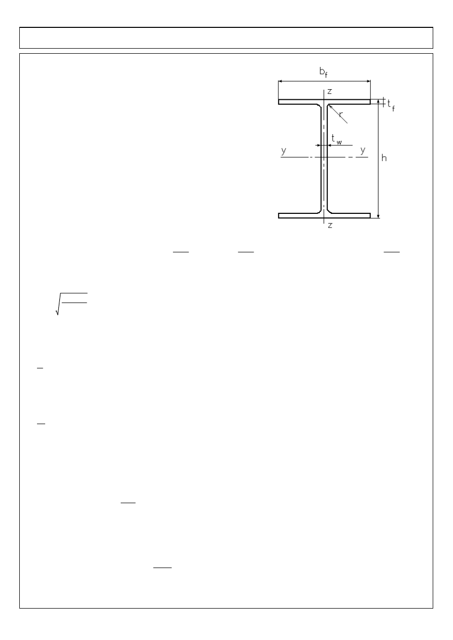
2.2 Design of the column
Initially accepted HEB 280
A
131cm
2
:=
Iz
6590cm
4
:=
iy
12.13cm
:=
h
280mm
:=
Iτ
144cm
4
:=
iz
7.09cm
:=
bf
280mm
:=
tf
18mm
:=
Iω
1130000cm
6
:=
tw
11mm
:=
Wply
1530.08cm
3
:=
r
24mm
:=
2.2.1 Class of section
Mechanical properties of the steel:
tf
18 mm
⋅
=
< 40mm
fy
355
N
mm
2
:=
fu
510
N
mm
2
:=
E
210GPa
:=
G
81000
N
mm
2
:=
The class of eccentrically compressed elements should be defined accordingly for the stress distribution arising at the
considered combination of loads - for this instance to the axial compression.
ε
235MPa
fy
0.814
=
:=
Flange in compression:
c
0.5 bf tw
−
(
)
⋅
r
−
:=
c
tf
6.139
=
<
9
ε
⋅
7.323
=
class 1
Web in bending and compression:
d
h
2 tf
⋅
−
2 r
⋅
−
:=
d
tw
17.818
=
<
38
ε
⋅
30.917
=
class 1
Section's class: 1
2.2.2 Resistance of cross section
a) compression
γM0
1.0
:=
NcRd
A fy
⋅
γM0
4.651
10
3
×
kN
⋅
=
:=
Resistance condition:
Combination of loads for N
max
(3):
Nmax
NEd3
162.65 kN
⋅
=
:=
Nmax
NcRd
0.035
=
<1
condition fulfilled
STEEL INDUSTRIAL HALL - LATERAL SYSTEM DESIGN
b) bending
The influence of the axial power on the plastic resistance of the section in bending.
- combination of loads for M
max
(2):
Mmax
MEd2
182.5 kNm
⋅
=
:=
NEd
NEd2
85.26 kN
⋅
=
:=
- the condition for the omission of the influence of the axial force on the plastic resistance of the section in bending in
relation to the y axis:
NEd
85.26 kN
⋅
=
<
0.25 NplRd
⋅
0.25 NcRd
⋅
1162.6 kN
⋅
=
:=
0.25
NEd
85.26 kN
⋅
=
<
0.5 d
⋅
tw
⋅
fy
⋅
γM0
382.69 kN
⋅
=
We can omit the influence of the axial force on the plastic resistance in bending.
The design bending resistance:
MplyRd
Wply fy
⋅
γM0
543.178 kNm
⋅
=
:=
Resistance condition:
Mmax
MplyRd
0.336
=
<1
condition fulfilled
c) shearing
The shearing resistance of the section
- area of flange:
Af
bf tf
⋅
5040 mm
2
⋅
=
:=
- area of the web:
Aw
d tw
⋅
2156 mm
2
⋅
=
:=
- effective shearing area:
Avz1
A
2 bf
⋅
tf
⋅
−
tw 2r
+
(
)
tf
⋅
+
4082 mm
2
⋅
=
:=
η
1
:=
Avz2
η Aw
⋅
2156 mm
2
⋅
=
:=
Avz
max Avz1 Avz2
,
(
)
4082 mm
2
⋅
=
:=
Af
Aw
2.338
=
>0.6
resistance of section:
VcRd
Aw
fy
3
γM0
⋅
⋅
441.892 kN
⋅
=
:=
resistance condition:
Combination of loads for N
max
(3):
Vmax
VEd4
33.07 kN
⋅
=
:=
Vmax
VcRd
0.075
=
<1
condition fulfilled
STEEL INDUSTRIAL HALL - LATERAL SYSTEM DESIGN
2.2.3 Buckling resistance of the column
Internal forces: design of column carried out for the combination of actions 2:
NEd
NEd2
85.26 kN
⋅
=
:=
MEd
MEd2
182.5 m kN
⋅
=
:=
VEd
VEd2
42.11 kN
⋅
=
:=
2.2.3.1 Buckling lengths
L - length of column in given plane of buckling
µ
- coefficient of buckling
a) length of the buckling in y axis:
Ly
H
13.5 m
=
:=
μy
1.5
:=
- partially fixed
Lcry
Ly μy
⋅
20.25 m
=
:=
b) length of the buckling in z axis:
Lz
H
2
6.75 m
=
:=
-spandrel beam
μz
1.0
:=
- pinned connection
Lcrz
Lz μz
⋅
6.75 m
=
:=
2.2.3.2 Buckling coefficient
a) length of the buckling in y axis (in plane of lateral system)
the reference value to appointing of the relative slenderness:
λ1
π
E
fy
⋅
:=
=
λ1
93.9
ε
⋅
76.399
=
:=
the relative slenderness in y axis:
λy
A fy
⋅
Ncr
:=
Ncr
=
λy
Lcry
iy
1
λ1
⋅
2.185
=
:=
imperfection factor:
αy
0.76
:=
parameter of curve of instability:
Φy
0.5 1
αy λy 0.2
−
(
)
⋅
+
λy
2
+
⋅
3.642
=
:=
buckling coefficient:
χy
1
Φy
Φy
2
λy
2
−
+
0.153
=
:=
b) length of the buckling in z axis (out of plane of lateral system)
the relative slenderness in y axis:
λz
A fy
⋅
Ncr
:=
Ncr
=
λz
Lcrz
iz
1
λ1
⋅
1.246
=
:=
imperfection factor:
αz
0.76
:=
parameter of curve of instability:
Φz
0.5 1
αz λz 0.2
−
(
)
⋅
+
λz
2
+
⋅
1.674
=
:=
buckling coefficient:
χz
1
Φz
Φz
2
λz
2
−
+
0.358
=
:=
STEEL INDUSTRIAL HALL - LATERAL SYSTEM DESIGN
2.2.3.3 Lateral buckling coefficient
The correction coefficient C
1
- accepted triangular distribution of bending moments
ψ
0
:=
k
1
:=
C1
1.879
:=
Critical moment M
cr
at the lateral buckling
Mcr
C1
π
2
E
⋅
Iz
⋅
Lz
2
⋅
Iω
Iz
Lz
2
G
⋅
Iτ
⋅
π
2
E
⋅
Iz
⋅
+
⋅
1333.6 kNm
⋅
=
:=
Relative slenderness at lateral buckling:
λLT
Wply fy
⋅
Mcr
0.638
=
:=
Parameter of curve of the lateral buckling:
λLT0
0.4
:=
β
0.75
:=
αLT
0.34
:=
ΦLT
0.5 1
αLT λLT λLT0
−
(
)
⋅
+
β λLT
( )
2
⋅
+
⋅
0.693
=
:=
The coefficient of lateral buckling:
χLT1
1
λLT
2
2.455
=
:=
χLT2
1
ΦLT
ΦLT
2
β λLT
2
⋅
−
+
0.9
=
:=
χLT
min
χLT1 χLT2
,
1
,
(
)
0.9
=
:=
2.2.3.4 Interaction factors
Coefficient of equivalent constant moment
Cmy
0.9
:=
- sway buckling mode
γM1
1
:=
NRk
A fy
⋅
4.651
10
3
×
kN
⋅
=
:=
kyy1
Cmy 1
λy 0.2
−
(
)
NEd
χy
NRk
γM1
⋅
⋅
+
⋅
1.115
=
:=
kyy2
Cmy 1 0.8
NEd
χy
NRk
γM1
⋅
⋅
+
⋅
0.987
=
:=
kyy
min kyy1 kyy2
,
(
)
0.987
=
:=
STEEL INDUSTRIAL HALL - LATERAL SYSTEM DESIGN
The coefficient C
mLT
at the triangular distribution of bending moments for
ψ
=0
CmLT
0.6
0.4
ψ
⋅
+
0.6
=
:=
>0.4
kzy1
1
0.1
λz
⋅
CmLT 0.25
−
NEd
χz
NRk
γM1
⋅
⋅
−
0.982
=
:=
kzy2
1
0.1
CmLT 0.25
−
NEd
χz
NRk
γM1
⋅
⋅
−
0.985
=
:=
kzy
max kzy1 kzy2
,
(
)
0.985
=
:=
2.2.3.5 Resistance check of column
∆MyEd
0
:=
MzEd
0
:=
∆MzEd
0
:=
MyRk
Wply fy
⋅
543.178 kNm
⋅
=
:=
MyEd
MEd
182.5 kNm
⋅
=
:=
NEd
χy NRk
⋅
γM1
kyy
MyEd
χLT
MyRk
γM1
⋅
⋅
+
0.489
=
< 1
NEd
χz NRk
⋅
γM1
kzy
MyEd
χLT
MyRk
γM1
⋅
⋅
+
0.419
=
< 1
conditions are fulfilled
STEEL INDUSTRIAL HALL - LATERAL SYSTEM DESIGN
2.2.4 Head of column
a) The load on the level of the head of the column:
The autorithative combination for the maximum value of the axial force in the top joint of the column
COMB 5 (dead load, snow load, winter):
Nmaxg
1.35 54.26
⋅
kN
1.5 59.6
⋅
kN
+
1.5 0.6
⋅
0.18
⋅
kN
+
162.81 kN
=
:=
b) assumptions:
Dimensions of the horizontal metal plate covering the column:
length:
lbg
h
2 20
⋅
mm
+
320 mm
=
:=
width:
bbg
max bf 2 20
⋅
mm
+
240mm
,
(
)
320 mm
=
:=
thickness:
tbg
16mm
:=
Dimensions of the rib:
thickness:
tg
16mm
:=
width:
bg
bbg
320 mm
=
:=
height:
hg
lbg
320 mm
=
:=
c) Welds connecting rib with the column
The thickness accepted from constructional conditions according to PN-90-03200:
anom
4mm
:=
>
0.2 tg
⋅
3.2 mm
=
anom
4mm
:=
<
0.7 tw
⋅
7.7 mm
=
anom
4mm
:=
>
2.5mm
anom
4mm
:=
<
16mm
The design resistance of the fillet weld
βw
0.8
:=
γM2
1.25
:=
fvwRd
fu
3
βw
⋅
γM2
⋅
294.449
N
mm
2
=
:=
The design resistance of fillet weld per unit length:
FwRd
fvwRd anom
⋅
1177.79
N
mm
=
:=
The required length of the weld:
lw.req
Nmaxg
4 FwRd
⋅
35 mm
=
:=
Accepted length of weld:
lw
max lw.req hg
,
(
)
320 mm
=
:=
STEEL INDUSTRIAL HALL - LATERAL SYSTEM DESIGN
c) The pressure to the web and rib
The range of pressure area:
width of bearing:
bc
80mm
:=
s
bc 2 tbg
⋅
+
112 mm
=
:=
The area of the pressure to web and rib:
Ag
bg tg
⋅
tw s tg
−
(
)
⋅
+
6176 mm
2
=
:=
The design resistance at load by axial force:
NcRd
Ag fy
⋅
γM0
2192.5 kN
=
:=
Resistance condition:
Nmaxg
NcRd
0.074
=
The resistance condition is fulfilled
Vertical displacement of post head
Udop
H
150
90 mm
⋅
=
:=
Up
85mm
:=
- from ROBOT
Up
85 mm
⋅
=
<
Udop
90 mm
⋅
=
condition is satisfied
STEEL INDUSTRIAL HALL - LATERAL SYSTEM DESIGN
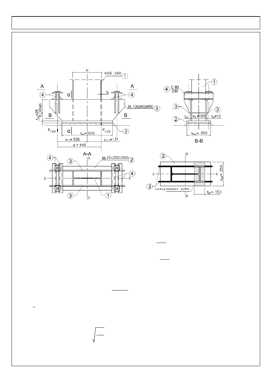
2.2.5 Column base
a) Assumptions
The geometry of the column base:
b) The resistance of the concrete
Assumptions:
class of concrete of foundations C25/30
fck
25
N
mm
2
:=
characteristic resistance of the concrete in compression
design resistance of the concrete in the compression
fcd
16.7
N
mm
2
:=
The design resistance of the connection in the pressure:
fjd
βj FRdu
⋅
beff leff
⋅
:=
βj
βj
2
3
:=
material coefficient of the foundation
The design resistance at the concentrated force acting on the concrete surface:
FRdu
Ac0 fcd
⋅
Ac1
Ac0
⋅
:=
Ac0
<
3 fcd
⋅
Ac0
⋅
STEEL INDUSTRIAL HALL - LATERAL SYSTEM DESIGN
area of pressure
Ac0
beff leff
⋅
:=
beff
beff
leff
effective width and length of the T-stub of flange and basis metal plate
Ac1
the area of distribution;
Ac1
Ac0
1.5
:=
Ac1
Ac0
fjd
βj FRdu
⋅
beff leff
⋅
:=
FRdu
=
βj Ac0
⋅
fcd
⋅
Ac1
Ac0
⋅
Ac0
=
1.5
βj
⋅
fcd
⋅
16.7
N
mm
2
=
c) Resistance condition of the compressed zone:
The maximum outreach of the pressure zone:
tp
25mm
:=
thickness of base plate
γm0
1
:=
c
tp
fy
3 fjd
⋅
γm0
⋅
⋅
67 mm
=
:=
The effective width b
eff
and length l
eff
of the T-stub of basis metal plate:
bdb
350mm
:=
tbt
12mm
:=
beff
min bdb bf 2 c tbt
+
(
)
⋅
+
,
350 mm
=
:=
lbd
500mm
:=
leff
min 0.5 lbd h
−
(
)
⋅
tf
+
c
+
tf 2 c
⋅
+
,
151 mm
=
:=
The design resistnace of compressed zone:
FcRd
fjd leff
⋅
beff
⋅
883.2 kN
=
:=
the level arm z at the dominant bending moment:
zTI
335mm
:=
zCr
0.5 h
tf
−
(
)
⋅
131 mm
=
:=
z
zTI zCr
+
466 mm
=
:=
the axial force:
The authoritative combination of loads COMB2
NEd
NEd2
85.26 kN
=
:=
MEd
MEd2
182.5 kNm
=
:=
FCEd
NEd
−
MEd
z
−
476.891
−
kN
=
:=
FCEd
476.9
−
kN
=
<
FcRd
883.2 kN
=
The resistance condition is fulfilled
STEEL INDUSTRIAL HALL - LATERAL SYSTEM DESIGN
d) The design resistance of tensioned zone
Accepted anchors ŁT30180 from steel S355
As
707mm
2
:=
fub
470
N
mm
2
:=
The carrying capacity of one anchor:
k2
0.9
:=
FtRd
k2 fub
⋅
As
⋅
γM2
239.2 kN
=
:=
Accepted that the anchor was properly fastened in the concrete, no tearing out.
the load of tension zone
FTEd
NEd
−
MEd
z
+
306.371 kN
=
:=
FTEd
306.371 kN
=
<
FTRd
2 FtRd
⋅
478.498 kN
=
:=
The resistance condition is fulfilled
e) The load by shearing force:
The auhoritative combination of loads: COMB 4
Vmax
VEd4
33.07 kN
=
:=
For the purpose of the takeover of the shearing force, under the metal plate of basis, cantilever from section
IPE 100 steel 235 was designed.
The carrying capacity of the section in shearing:
Area of flange:
bf1
55mm
:=
tf1
5.7mm
:=
Af
bf1 tf1
⋅
313.5 mm
2
=
:=
Area of web:
d
100mm
2 7
⋅
mm
−
2 5.7
⋅
mm
−
74.6 mm
=
:=
tw
4.1mm
:=
Aw
d tw
⋅
305.86 mm
2
=
:=
Af
Aw
1.025
=
> 0.6
fy
235MPa
:=
VcRd
Aw
fy
3
γM0
⋅
⋅
41.498 kN
=
:=
Vmax
VcRd
0.797
=
< 1
The resistance condition is satisfied
f) The resistance of the vertical fillet welds connecting the column with trapezoidal plates
anom
5mm
:=
>
0.2 tbt
⋅
2.4 mm
=
anom
5mm
:=
<
0.7 tf
⋅
12.6 mm
=
anom
5mm
:=
>
2.5mm
anom
5mm
:=
<
16mm
STEEL INDUSTRIAL HALL - LATERAL SYSTEM DESIGN
The design resistance of the fillet welds
βw
0.8
:=
γM2
1.25
:=
fvwRd
fu
3
βw
⋅
γM2
⋅
294.449
N
mm
2
=
:=
The design resistance of fillet weld per unit length:
FwRd
fvwRd anom
⋅
1472.24
N
mm
=
:=
FcEd
355kN
:=
The required length of the weld:
lw.req
FcEd
4 FwRd
⋅
60 mm
=
:=
Accepted length of weld:
hbt
240mm
:=
lw
max lw.req hbt
,
(
)
240 mm
=
:=
g) The design resistance of the horizontal and trapezoidal metal plates:
The bending moment i nsection
α
-
α
MTEd
FTEd zTI
h
2
−
⋅
59.742 kNm
=
:=
The class of section:
web bending
c
hbt
:=
c
tbt
20
=
<
72
ε
⋅
58.58
=
class I
flange compression - cantilever part
c
0.5 bdb bf
−
(
)
⋅
tbt
−
0.023 m
=
:=
tbd
25mm
:=
c
tbd
0.92
=
<
9
ε
⋅
7.323
=
class I
flange compression - span part
c
bf
:=
c
tbd
11.2
=
<
33
ε
⋅
26.849
=
class I
I class of section
STEEL INDUSTRIAL HALL - LATERAL SYSTEM DESIGN
The design plastic resistance of two trapezoidal metal plates at shearing
the effective area at shearing
Avbt
2 hbt
⋅
tbt
⋅
5760 mm
2
=
:=
VplRd
Avbt fy
⋅
3
γM0
⋅
781.501 kN
=
:=
resistance condition:
FcEd
VplRd
0.454
=
< 1
The resistance condition is fulfilled
The design plastic resistance of two trapezoidal metal plates at bending
Because the condition
FcEd
VplRd
0.454
=
< 0.5
is fulfilled, there is no necessity of taking into account shearing
influence on the bending reistance.
geometric and endurance parameters of the section:
yc
bdb tbd
⋅
0.5
⋅
tbd
⋅
2 hbt
⋅
tbt
⋅
0.5 hbt
⋅
tbd
+
(
)
⋅
+
bdb tbd
⋅
2 hbt
⋅
tbt
⋅
+
65.1 mm
=
:=
Iy
bdb tbd
3
⋅
12
bdb tbd
⋅
yc 0.5 tbd
⋅
−
(
)
2
⋅
+
2
tbt hbt
3
⋅
12
tbt hbt
⋅
yc
tbd 0.5 hbt
⋅
+
(
)
−
2
⋅
+
⋅
+
8.908
10
7
×
mm
4
=
:=
Wpl1
Iy
tbd hbt
+
yc
−
4.456
10
5
×
mm
3
=
:=
Wpl2
Iy
yc
1.368
10
6
×
mm
3
=
:=
Wply
min Wpl1 Wpl2
,
(
)
4.456
10
5
×
mm
3
=
:=
the design resistance in bending
McRd
Wply fy
⋅
γM0
104.726 kNm
=
:=
The resistance condition:
MTEd
McRd
0.57
=
< 1
The resistance condition is fulfilled
STEEL INDUSTRIAL HALL - LATERAL SYSTEM DESIGN
h) The resistance of fillet welds connecting metal plate of the basis with trapezoidal plates
anom
6mm
:=
>
0.2 tbd
⋅
5 mm
=
anom
6mm
:=
<
0.7 tbt
⋅
8.4 mm
=
anom
6mm
:=
>
2.5mm
anom
6mm
:=
<
16mm
Total length of welds:
lsp
2 2 lbd
⋅
h
−
(
)
⋅
1440 mm
=
:=
Stresses in welds:
from axial force:
σ1
FcEd
anom 2
⋅
2 leff
⋅
tf
−
(
)
⋅
2
73.607
N
mm
2
=
:=
σ2
0.9 fu
⋅
γM2
367.2
N
mm
2
=
:=
σp
min
σ1 σ2
,
(
)
73.61
N
mm
2
=
:=
τp
σp
:=
from shearing force COMB2:
VEd2
42.11 kN
=
Vsp
VEd2
2 lbd h
−
(
)
⋅
lsp
⋅
12.867 kN
=
:=
τpl
Vsp
4 anom
2
⋅
89.354
N
mm
2
=
:=
The resistance condition of the welds:
σp
2
3
τp
2
τpl
2
+
⋅
+
0.5
213.599
N
mm
2
=
<
fu
βw γM2
⋅
510
N
mm
2
=
The resistance condition is fulfilled

STEEL INDUSTRIAL HALL - LATERAL SYSTEM DESIGN
kNm
kN m
⋅
:=
STEEL INDUSTRIAL HALL - LATERAL SYSTEM DESIGN
I case: pressure
cpiP
0.2
:=
II case: suction
cpiS
0.3
−
:=
Wind load on the girder:
on surface of the roof:
weG
qp
1.2
−
(
)
⋅
0.89
−
kN
m
2
⋅
=
:=
weH
qp
0.7
−
(
)
⋅
0.519
−
kN
m
2
⋅
=
:=
weI
qp
0.2
−
(
)
⋅
0.148
−
kN
m
2
⋅
=
:=
internal pressure:
wiP
qp cpiP
⋅
0.148
kN
m
2
⋅
=
:=
wiS
qp cpiS
⋅
0.223
−
kN
m
2
⋅
=
:=
cs
1
:=
cd
1
:=
c
0.3m
:=
α
2.86deg
:=
b
2.7m
:=
e
14.75 m
⋅
:=
l
6m
:=
STEEL INDUSTRIAL HALL - LATERAL SYSTEM DESIGN

STEEL INDUSTRIAL HALL - LATERAL SYSTEM DESIGN
fjd
1.5
βj
⋅
fcd
⋅
:=
Wyszukiwarka
Podobne podstrony:
Mathcad straty zbiornik id 287204
projekt Mathcad KOMIN moj id 829609
BAT przet zel i stal czB id 807 Nieznany
Eurokody mostowe mathcad nosnosc sworzni id 165476
MathCAD Cwiczenia praktyczne id 287096
Mathcad Zbyszek obliczenia1 id 287222
Mathcad stal projekt 2 RŁ
Mathcad Schody tuuu id 287191
Mathcad cwiczenia cwmcad id 287 Nieznany
Mathcad Sprzeglo id 287200
Mathcad Mathcad 2 id 287140
Mathcad JB beton wersja 2 id 287131
Mathcad 14 (1) id 287078
Stal cz 1 Mathcad, ania jarzak
instrukcja Mathcad1 2012 id 216 Nieznany
Mathcad KOMIN id 287138
więcej podobnych podstron